Article

Performance and Feasibility Study of a Standing Column Well (SCW) System Using a Deep Geothermal Well

1
Department of Architectural Engineering, Pusan National University, 2 Busandaehak-ro 63, Geomjeong-gu, Busan 609-735, Korea
2
Division of Geologic Environment, Korea Institute of Geoscience and Mineral Resources, 124, Gahang-no, Yuseong-gu, Daejeon 305-350, Korea
*
Author to whom correspondence should be addressed.
Energies 2016, 9(2), 108; https://doi.org/10.3390/en9020108
Submission received: 7 December 2015 / Revised: 4 February 2016 / Accepted: 4 February 2016 / Published: 17 February 2016

Abstract

:
Deep geothermal heat pump systems have considerable energy saving potential for heating and cooling systems that use stable ground temperature and groundwater as their heat sources. However, deep geothermal systems have several limitations for real applications such as a very high installation cost and a lack of recognition as heating and cooling systems. In this study, we performed a feasibility assessment of a Standing Column Well (SCW) system using a deep geothermal well, based on a real-scale experiment in Korea. The results showed that the temperature of the heat source increased up to 42.04 °C in the borehole after the heating experiment, which is about 30 °C higher than that of normal shallow geothermal wells. Furthermore, the coefficient of performance (COP) of the heat pump during 3 months of operation was 5.8, but the system COP was only 3.6 due to the relatively high electric consumption of the pump. Moreover, the payback period of the system using a deep well for controlled horticulture in a glass greenhouse was calculated as 6 years compared with using a diesel boiler system.

1. Introduction

Renewable energy sources have attracted attention in recent years, due to concerns about nuclear power plants and the depletion of fossil fuels. Since the announcement of the “Solar Heating and Cooling Demonstration Act” in 1974 [1], the United States (US) have promoted policies supporting the use of renewable energy sources. Japan established the New Energy Development Organization (NEDO) in 1980 to support the development of renewable energy systems and promote the use of renewable energy [2,3]. In Korea, the “Act on the Promotion of the Development, Use, and Diffusion of New and Renewable Energy” was revised in 2014. According to the regulation, public facilities of more than 1000 m2 must cover 12% of their energy needs with renewable energy [
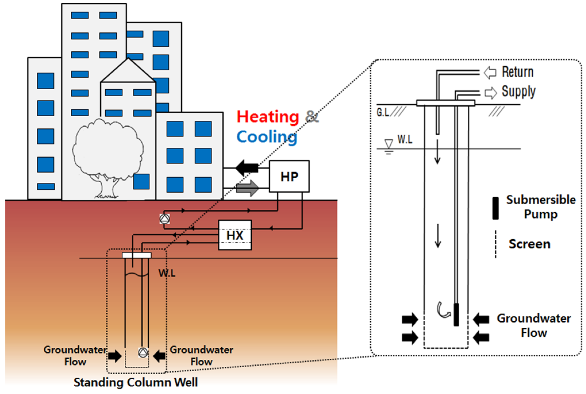
4]. Therefore, various renewable energy systems have been introduced in Korea. The installation of Ground Source Heat Pump (GSHP) systems for the heating and cooling of buildings is rapidly growing in Korea. Generally, GSHPs are divided into closed loop systems, which are based on the circulation of a heat carrier fluid into a buried pipe loop, and open loop systems, which are based on heat exchange with groundwater [5]. Another classification can be made according to the depth crossed by the ground heat exchangers, which are thus divided into shallow (up to 300 m) and deep (over 300 m) geothermal heat pumps, with shallow systems largely prevailing over deep systems. Although deep geothermal heating systems are more efficient than shallow systems, the research and technological development of these systems is still far from being satisfactory, since the installation costs are still very high. An investigation of the physical and thermal properties of the target area ground, along with a quantitative analysis of the available heat, is required for the use of deep geothermal energy, which has considerable potential due to the high temperature of the source. In addition, the time trend of the energy needs of the facility should be known. For the utilization of deep geothermal energy in the industrial and public welfare sectors, initial costs (considering the potential of deep geothermal energy) should be considered, and an objective Life Cycle Cost (LCC) is also necessary.
Nguyen et al. [6] evaluated the influence of groundwater flow in fractured aquifers using a numerical coupled model of the Standing Column Wells (SCW) systems. With their model, they achieved a good agreement with reference numerical solutions. Park et al. [7] studied Ground Water Heat Pump (GWHP) systems through a field test and numerical studies. The analysis confirmed that thermal dispersivity is a very important design factor when dealing with larger GWHP systems. Casasso et al. [8] developed a model of thermal recycling in GWHPs, which has been validated by numerical simulations with FEFLOW. This tool can be utilized for the design of GWHPs. Lo Russo et al. [9,10,11] modeled GWHPs to assess the hydrogeological sustainability of water reinjection in a plant installed at the Politecnico di Torino (Italy) for the cooling of various buildings. Different scenarios were analyzed that differ significantly in terms of both overall plant costs (investments, maintenance, and total electricity consumption) and environmental impact. In order to evaluate the Thermally Affected Zone (TAZ), numerical simulations were performed. Minea [12] conducted an experiment in the heating-cooling mode of two standing column wells that were shallower than the closed-loop system. The author concluded that the heating performance of the system without an artificial groundwater exchange is relatively high for limited periods of time. Efficient dehumidification in the free cooling mode is not achievable.
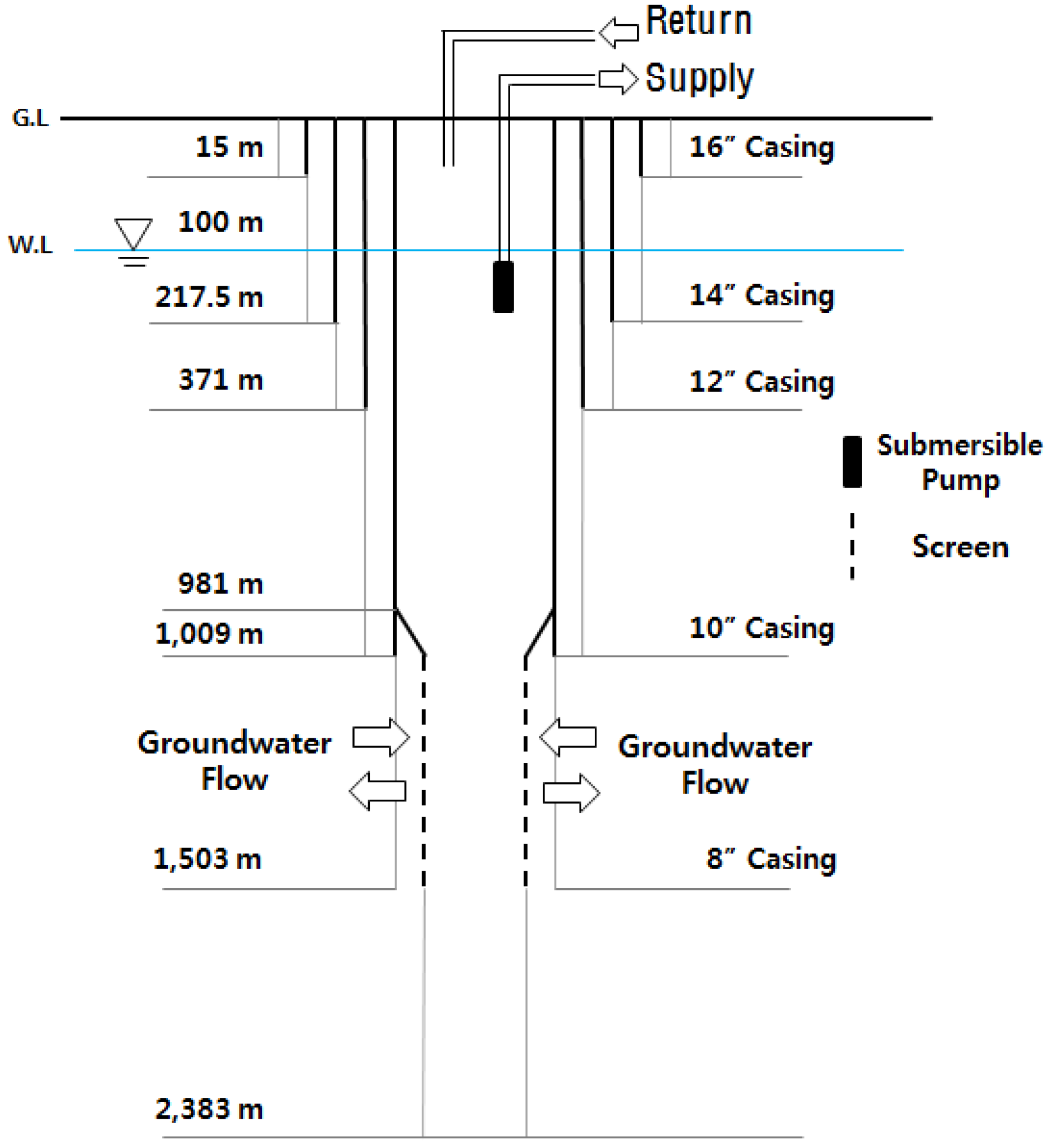
Closed-loop and open-loop systems, using shallow geothermal energy, are predominantly used in research and technological development in order to apply geothermal heat to buildings globally. Little research has been conducted regarding heat source temperature changes and the amount of energy usage. The Korea Institute of Geoscience and Mineral resources (KIGAM) conducted an evaluation of deep geothermal feasibility, aimed at the Korean peninsula, in order to assess the domestic geothermal energy reserves. According to the survey, a temperature of 90 °C was measured at a depth of 2385 m. Assuming the same ground temperature gradient below a depth of 2 km or more, a geothermal reservoir temperature of 180 °C could be obtained at a depth of 5 km [13,
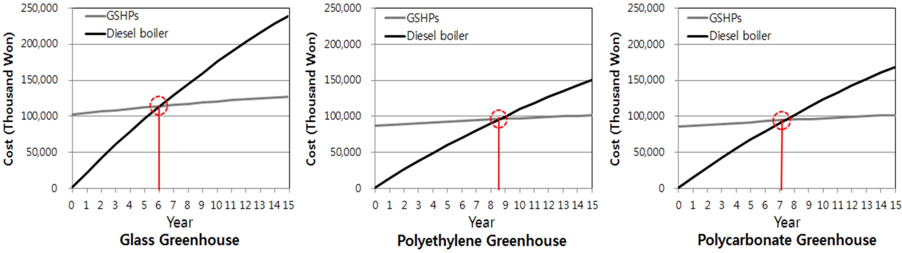
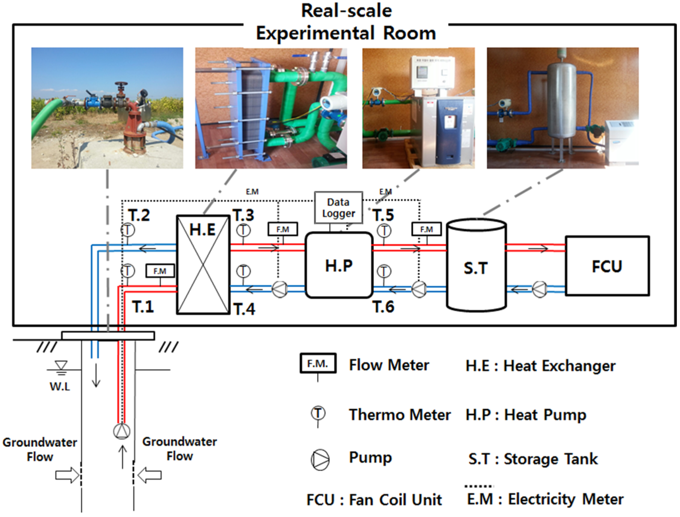
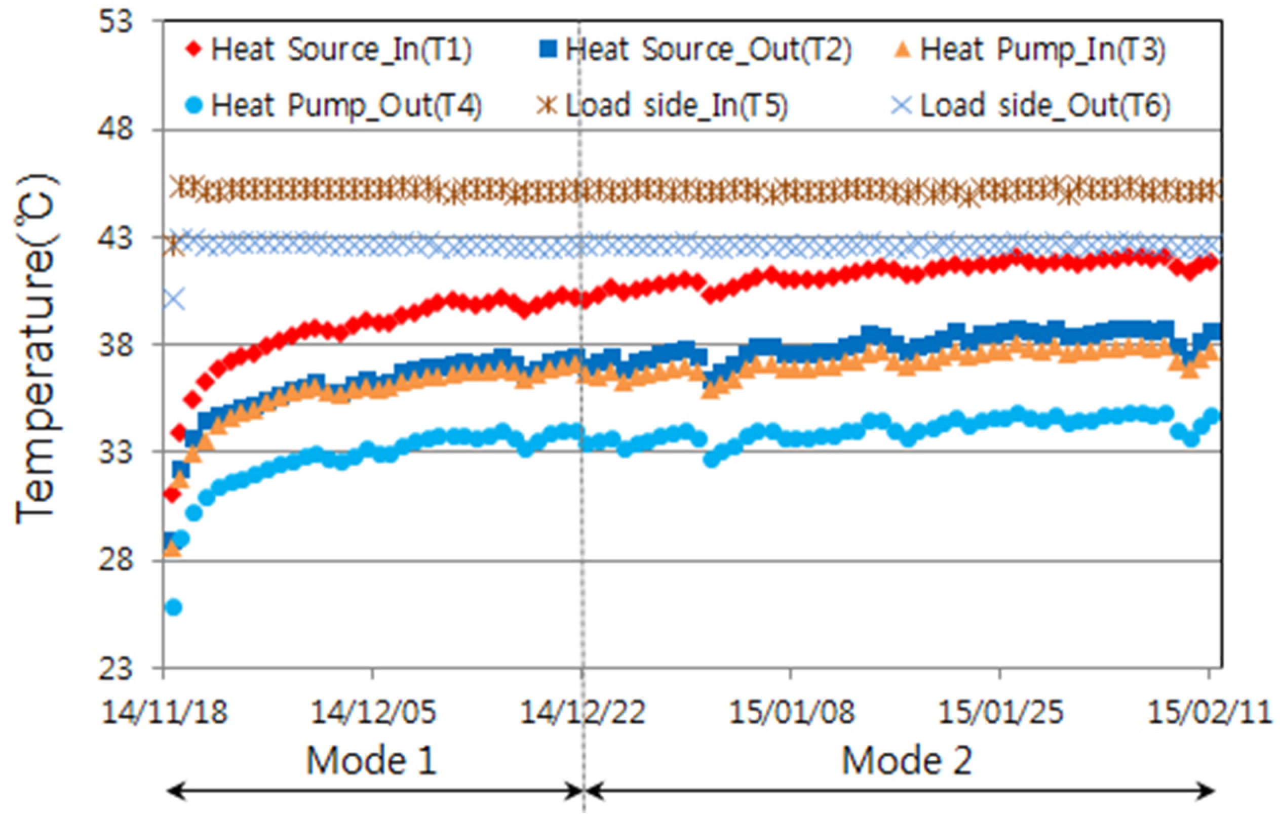
14]. Thus, in this study, real-scale testing equipment was constructed, and the actual energy availability was calculated for a deep geothermal well installed in Soenggok-ri, Heunghae-eup, Pohang-si, South Korea in order to evaluate the availability of deep geothermal energy. On the basis of the results, an evaluation was performed on each area for its potential use in controlled horticulture. Furthermore, on the basis of the LCC, the economics of the deep geothermal system were analyzed, and a comparison was made with existing heating boilers.

2. Summary of the Heating Experiment

2.1. Site Description

The target location of this experiment is the Heungae area of northern Pohang, Gyeongbuk, in South Korea. South Korea lies at a latitude of 36.02° N and a longitude of 129.33° E. In regard to the weather in Pohang, which is located in the southeastern part of the Korean peninsula, where the annual mean temperature and precipitation are 14.2 °C and 1152 mm, respectively. Pohang faces the East Sea and has a moderate climate due to the presence of the ocean and the warm current [15]. The ground surface of this area is a depositional surface belonging to the Gyeongsang supergroup from the Cretaceous period. The stony crystal tuff, biotite granite, felsite, and crystal tuff are distributed throughout the region, constituting the bedrock of the Pohang basin [13]. The location of the experiment is one of the large energy potential areas in South Korea [16]. In research started in 2003, a deep borehole was installed for deep geothermal energy resource development and a heating experiment was carried out using one borehole placed between four deep geothermal wells.

2.2. Summary of the Experiment and Heating System

In this study, a heating experiment was performed using a SCW, as shown in Figure 1. In these plants, the same deep geothermal well is used both for the abstraction and the injection of groundwater, which is used as a heat source for the heat pump.
SCW systems have attracted increasing attention due to their advantages such as low construction cost and high heat exchange rate per well depth compared to the closed-loop system, because they directly use groundwater as a heat sink, thus maintaining a constant temperature [17,18]. A real-scale laboratory was constructed and GSHPs experimental equipment was used to examine the feasibility of the deep SCW. The laboratory is located in Heunghae-eup, Pohang, South Korea, and was constructed using a container structure of 12 m2 in area. Figure 2 shows a schematic diagram of the equipment system developed in this study. The system configuration includes a heat exchanger, a heat pump, and load-side units, as shown in Table 1 [14,18].
The ground heat exchanger is a SCW, with a depth of 2383 m, as shown in Figure 3; water is abstracted using 29.42 kW submersible pumps. The heat pump system (WaterFurnace, Wayne, NJ, USA) is composed of a plate-type heat exchanger, a heat pump with a 5 RT capacity for heating and cooling, and a circulation pump. The load part (SHINWOO, Paju, South Korea), is composed of a 200 L thermal storage tank a Fan Coil Unit (FCU) with a 14.5 kW capacity for heating, and a circulation pump. In order to analyze the temperature change of water within the borehole and the system performance, monitoring was carried out by installing a temperature sensor, a flow meter, and a power meter around the plumbing and heat pump, as shown in Table 2. A total of six temperature sensors were installed as shown in Figure 3 in order to measure the temperature of the heat source. The circulation flow was measured using an electronic flow meter, and a single-phase two-wire power meter was used to measure the amount of electricity consumed in the operation of the heat and circulation pumps. A data logger was used to save the data measured in the SCW system in this study [14,18].

2.3. Experiment Method

Table 3 shows the test methods used during the heating operation of the system. A simulated cooling load was installed inside the laboratory, taking into account the lack of a heating load during the day.
A heating operation test was performed in order to analyze the maximum heating load that could be provided by the system, in continuous operation, without regard of the bleeding operation of the SCW. The heating test was conducted over a period of 3 months from 18 November 2014 to 11 February 2015. The heat source temperature within the well, as well as the system performance (in accordance with the flow rate change and the FCU set temperature) were compared and analyzed. The heat pump load-side temperature was set at 45 °C. The temperature difference (ΔT) at the heat exchanger was set at 5 °C. When deep geothermal wells are applied in controlled horticultural farms, a quantitative analysis of the energy consumption, per plant, is needed to determine the heating set temperature. Therefore, an FCU temperature change (from 30 to 22 °C) was set. The power consumption of the installed submersible pump was 15.3 kW during the drawdown test at 416 L/min. Lower flow rates of 70 and 50 L/min were used in the experiment, and the power consumption of the heat pump hence proportionally diminished to 2.50 and 1.65 kW, respectively.

3. Experimental Results

3.1. Temperature Change of the Heat Source Water

Figure 4 shows the change of the water temperature during the heating operation of the systems by using the deep geothermal well. T1 (Heat source_In) and T2 (Heat source_Out) are the time series of the water temperature at the inlet and outlet of the borehole, respectively. After the heating operation at 70 L/min and 30 °C FCU set point had ended, the temperatures of the entering and return water were 40.06 and 36.99 °C, respectively; these temperatures increased to 41.84 and 38.57 °C in the second period at 50 L/min and 22 °C FCU set point.
A maximum entering water temperature was achieved of 42.04 °C, which then decreased to 41.84 °C at the end of the experiment; this is considered to reliably respond to the heating load, per crop, when a deep geothermal well is predominantly used in a controlled horticulture farm. T3 (Heat pump_In) and T4 (Heat pump_Out), in Figure 4, are the water temperature time series at the outlet of the heat pump, which is connected to the plate type heat exchanger. In T5 (Load side_In) and T6 (Load side_Out), in Figure 4, the heat source water temperature of the load side, and the mean inlet and outlet temperatures during the heating operation were measured as 45.16 and 42.62 °C, respectively, as the heat pump temperature was set at 45 °C. The temperature of heat source in this system gradually increased with time, indicating that the geothermal energy potential is greater than that resulting from the experiment.

3.2. Heating Performance of the Heat Pump

Figure 5 shows the average heat exchange rate and the electric power consumption of the system during the heating operation of the GSHPs. The heat exchanger rate was calculated using Equation (1):
Q = C p   ×   m ˙ w   ×   Δ T
where Q: Heat exchange rate (kW), Cp: specific heat (kJ/kg·°C), m ˙ w : flow rate (L/s), ΔT: temperature difference (°C).
The average heat exchange rate of the system is 25.77 kW at a flow rate of 70 L/min and 27.25 kW at a flow rate 50 L/min.
This is due to the continuous increase of the temperature of the heat source. The mean power consumption of the circulation pump on the source and load sides is 0.5 kW, and the power consumption of the heat pump is 4.7 kW.
Figure 6 shows the COP of the heat pump (HP.COP) and of the whole system (S.COP) during the heating experiment, calculated using Equations (2) and (3):
H P . C O P = Q W h p
S . C O P = Q W h p + W p
where ΣQ: total heating power (kW), ΣWhp: electricity consumption of the heat pump (kW), ΣWp: electricity consumption of the circulation pump (kW).
The average COP of the heat pump is 5.5 and 5.8 for the first and the second part of the heating experiment, respectively, i.e., at flow rates of 70 and 50 L/s, respectively. These values are noticeably higher than 3.1, i.e., the minimum standard value according to [17]. The heat source temperature kept increasing up to 41.04 °C, as shown in Figure 4. Thus, we consider that the heat exchange rate of the system and the heat pump performance would be much higher under optimal operating conditions. The average system COP, reflecting the power consumption of each facility system is 3.1 and 3.6 at a flow rate of 70 and 50 L/s, respectively. The reason why the system COP is much lower than that of the heat pump is that the power consumption of the submersible pump was relatively high compared to that of the closed-loop system. If the submersible pump were optimized, the system COP could be improved substantially.

4. Feasibility Analysis of the Controlled Horticulture Scenario

4.1. Simulation Summary

A quantitative analysis of the energy consumption in buildings served by a geothermal plant is required in order to assess the feasibility of the utilization of geothermal energy. Thus, in this study, a heating load analysis was performed considering the standard materials used for greenhouse covers in Korea; i.e., glass, polyethylene, and polycarbonate [19] (Figure 7). The software TRNSYS (University of Wisconsin, Madison, WI, USA) 17 was adopted for the dynamic energy simulation of these standard greenhouses. TRNSYS is able to model complex energy systems, which are reproduced by assembling modular components modeled by libraries (Types). The simulation conditions are summarized in Table 4. The weather data from the Meteonorm was utilized, which is in Ulsan, near Pohang. The product cultivated in the controlled horticultural farms is assumed to be paprika, and the indoor temperature was set at 18 °C. The indoor temperature control of the greenhouse is performed by ventilation, and the amount of ventilation was set at 1.57 times/h according to the prescriptions of Korea Rural Development Administration (RDA) [20]. In this study, the operation of the greenhouse time was set as a 24-h continuous operation, and the heating energy required per unit area (according to the operation conditions of the greenhouse) was calculated.

4.2. Simulation Results

Figure 8 and Table 5 show the results of the heating load analysis. The results, according to the cover type, showed that the total annual heating load is 146.77 MWh/year for glass, 85.33 MWh/year for polyethylene, and 96.04 MWh/year for polycarbonate. It was confirmed that a glass greenhouse consumes about 1.6 times more energy than a greenhouse covered with other materials, because of the higher transmissivity (U-value). The solar energy transmittance (G-value) of polycarbonate is lower than that of polyethylene, and hence the heating consumption of the polycarbonate greenhouse is higher, due to the lower solar gains. The peak heating load was calculated as 83.58 kW for glass, 58.64 kW for polyethylene, and 56.42 kW for polycarbonate. Assuming that the GWHP has a flow rate of 300 m3/day, the estimated thermal power is 72.74 kW, which is sufficient to cover the peak load of the polyethylene and polycarbonate greenhouse, but not that of the glass-covered greenhouse.

5. Economic Analysis

5.1. Summary of Economic Analysis

Depending on the outer cover type of the greenhouse, and hence on the heating load, a comparative economic analysis was carried out as shown in Figure 9. The Life Cycle Cost (LCC) and the Return On Investment (ROI) were calculated adopting the present value analysis method, which is described by the following equations:
P F = F ( 1 + i ) n
P A = A [ ( 1 + i ) 1 ] i ( 1 + i ) n
P = PF + PA
where PF: the present value of future cash, PA: capitalization factor of annuity, F: cost incurred after n years, A: annual cost, i: discount value.

5.2. Calculation of Initial Cost

The initial cost was calculated as shown in Table 6, based on the heating peak load on which the required power of the heat pump/boiler depends.
The initial cost of the boiler was taken from the price list of the Kiturami Company in South Korea [21]. Assuming a depth of 1 km for the SCW, the excavation cost of the geothermal heat exchanger was calculated, based on estimates from Korean GSHP companies. The cost of the heat pump, depending on the power, was taken from [22]. The initial cost of the geothermal heating system is 38 to 46 times higher than that of the oil boiler, as reported in Table 6. Two oil boilers were considered, Boiler 1 with a power of 116.3 kW and an efficiency of 83%, and Boiler 2 with a power of 81.4 kW and an efficiency of 82%.

5.3. Calculation of Operation Cost

The LCC of each system was calculated considering both the energy and the maintenance costs. Table 7 reports the price of diesel in Korea as of June 2015 [23] and the heating value of diesel in an ideal boiler considering the efficiency of Boilers 1 (83%) and 2 (82%).
The heat pump COP should consider a variety of effects, such as the operation method of the system, the ground properties etc., in order to calculate the operating cost of the GSHP. For this reason, the operation costs were calculated by setting the heat pump COP to 3.1, according to the minimum performance standard value reported in [17]. The special tariff of the Korea Electric power Corporation was used to calculate the cost of electricity to feed the heat pump [24]. For the maintenance costs, it was assumed that the oil boilers need to be replaced after 10 years, while the heat pump does not need to be replaced in a 20 year lifespan. Table 8 reports the annual energy consumption of each system.
Table 9 reports the annual operation costs of the oil boiler and the GSHPs. The annual operation costs are reduced by 19 million South Korean won (SKW) for about 12 million SKW in the plastic greenhouse, and about 13 million SKW in the polycarbonate greenhouse, when using diesel oil as the heat source.

5.4. Payback Period Analysis

An ROI analysis was performed using the present value analysis method, converting all costs (annual operation and system maintenance costs, etc.) that occur in the life cycle of the energy supply system. The average value of the three-year expiration Treasury bond for 10 years (2005–2014), in the Korea Bank economic Statistics System was 3.94% [25]. In the case of the oil boiler, assuming that boiler replacement and installation costs are incurred every 10 years, the non-recurring cost was calculated. Figure 10 shows the LCC analysis of the diesel oil boiler and the GSHPs for the different cover materials. An economical benefit of adopting GSHPs is found for all materials, as the payback period is shorter than the 15 years plant lifetime considered in our analysis, i.e., about 6 years for the glass greenhouse (which is characterized by higher energy consumption), about 9 years for the polyethylene greenhouse, and 8 years for the polycarbonate greenhouse.

6. Conclusions

In this study, the system performance and availability of deep geothermal energy were analyzed through empirical heating experiments on a SCW-type deep geothermal well installed in Pohang-Si, South Korea. Also, a heating load analysis was conducted according to the outer cover materials, by using a dynamic thermal analysis simulation tool. Based on the results of the energy simulation, the economics of the deep geothermal well were analyzed, comparing it with a conventional oil boiler. The following results were obtained.
  • The heating experiment at the deep geothermal well showed that the temperature increased over time, achieving a final value of 41.84 °C. The performance analysis of the GSHPs showed that the average HP.COP is 5.5 with a flow rate of 70 L/min and a FCU set temperature of 30 °C, and 5.8 with a flow rate of 50 L/min and a FCU set temperature of 22 °C. Such performance is much greater than the minimum standard value specified in ASHRAE. A deep geothermal well for a greenhouse with a dominant heating load is therefore expected to operate efficiently in the long term.
  • The LCC analysis results for each outer cover type, when replacing an existing diesel oil boiler with GSHPs, show economic profits after about 6 years for a greenhouse of glass, after 9 years for polyethylene, and after 8 years for polycarbonate.
In the future, optimal operating conditions and design methods will be established during long-term heating operation, using a deep geothermal well, through continuous monitoring of the systems.

Acknowledgments

This research was supported by the Basic Research Project of the Korea Institute of Geoscience and Mineral resources (KIGAM) funded by the Ministry of Science, ICT and Future Planning of Korea (GP2011-003) and the Basic Science Research Program through the National Research Foundation of Korea (NRF) funded by the Ministry of Education, Science and Technology (2015R 1D 1A3A01020132).

Author Contributions

All authors contributed equally to this work. All authors designed the experiment and the simulations, discussed the results and implications and commented on the manuscript at all stages.

Conflicts of Interest

The authors declare no conflict of interest.

References

  1. U.S. Government Accountability Office (GAO). Available online: http://www.gao.gov/products/EMD-80-41 (accessed on 15 January 2016).
  2. Renewable Energy Country Profiles Asia; International Renewable Energy Agency (IRENA): Abu Dhabi, UAE, 2013.
  3. New and Renewable Energy White Paper; New and Renewable Center of Korea Energy Agency: Yongin, Korea, 2014.
  4. Korea Ministry of Government Legislation. National Law Information Center. Available online: http://www.law.go.kr (accessed on 8 July 2015).
  5. Nam, Y.J.; Chae, H.B. Numerical simulation for the optimum design of ground source heat pump system using building foundation as horizontal heat exchanger. Energy 2014, 73, 933–942. [Google Scholar] [CrossRef]
  6. Nguyen, A.; Pasquier, P.; Marcotte, D. Influence of groundwater flow in fractured aquifers on standing column wells performance. Geothermics 2015, 58, 39–48. [Google Scholar] [CrossRef]
  7. Park, B.H.; Bae, G.O.; Lee, K.K. Importance of thermal dispersivity in designing groundwater heat pump (GWHP) system: Field and numerical study. Renew. Energy 2015, 83, 270–279. [Google Scholar] [CrossRef]
  8. Casasso, A.; Sethi, R. Modeling thermal recycling occurring in groundwater heat pumps (GWHPs). Renew. Energy 2015, 77, 86–93. [Google Scholar] [CrossRef]
  9. Russo, S.L.; Civita, M.V. Open-loop groundwater heat pumps development for large buildings: A case study. Geothermics 2009, 38, 335–345. [Google Scholar] [CrossRef]
  10. Russo, S.L.; Taddia, G.; Baccino, G.; Verda, V. Different design scenarios related to an open loop groundwater heat pump in a large building: Impact on subsurface and primary energy consumption. Energy Build. 2011, 43, 347–357. [Google Scholar] [CrossRef]
  11. Russo, S.L.; Taddia, G.; Verda, V. Development of the thermally affected zone (TAZ) around a groundwater heat pump (GWHP) system: A sensitivity analysis. Geothermics 2012, 43, 66–74. [Google Scholar] [CrossRef]
  12. Minea, V. Experimental investigation of the reliability of residential standing column heat pump systems without bleed in cold climates. Appl. Therm. Eng. 2013, 52, 230–243. [Google Scholar] [CrossRef]
  13. Hwang, S.H.; Park, I.H.; Song, Y.H. Interpretation of geophysical well logs from deep geothermal borehole in Pohang. J. Geophys. Geophys. Explor. 2007, 10, 332–344. [Google Scholar]
  14. Development of Technology for CO2 Geological Storage and Securing Green Energy Resources in Deep Geo-Environment: Characterization of Geothermal Anomalies and Geothermal Resource Assessment in the Southeastern Part of the Korean Peninsula; Korea Institute of Geoscience and Mineral Resources (KIGAM): Daejeon, Korea, 2014.
  15. Korea Meteorological Administration Resources (KMA). Available online: http://www.kma.go.kr (accessed on 2 July 2015).
  16. Web site of Korea Institute of Energy Research (KIER). Available online: http://kredc.kier.re.kr/eBookFile/GEO/GEO.HTML (accessed on 17 January 2016).
  17. Geothermal Heat Pump Manual: A Design and Installation Guide for New York City; New York City Department of Design and Construction: New York, NY, USA, 2012.
  18. Cho, J.H.; Kim, H.C.; Nam, Y.J. Study on the performance test of geothermal heat pump system using a deep well. In Proceedings of the SAREK 2014 Winter Annual Conference, Seoul, Korea, 28 November 2014; pp. 413–416.
  19. Park, J.C. Design direction and standard model of Korean-Type Glasshouse. Korean Soc. Bio-Environ. Control 1993, 6, 16–30. [Google Scholar]
  20. New Agricultural Energy-Saving Technology for the Improvement of Farm Management Balance; Korean Rural Development Administration (RDA): Jeonju, Korea, 2010.
  21. Kiturami Boiler. Available online: http://krb.co.kr/products (accessed on 21 June 2015).
  22. New and Renewable Center of Korea Energy Agency. Available online: http://www.knrec.or.kr (accessed on 21 June 2015).
  23. Korea National Oil Corporation (KNOC). Available online: http://www.knoc.co.kr (accessed on 22 June 2015).
  24. Electric Power Corporation (KEPCO). Available online: http://home.kepco.co.kr (accessed on 22 June 2015).
  25. Economic Statistics System (ECOS). Available online: http://ecos.bok.or.kr (accessed on 13 July 2015).
Figure 1. Standing Column Well (SCW) system.
Energies 09 00108 g001
Figure 2. Schematic diagram of the Ground Source Heat Pump (GSHP) systems. Reproduced with permission from [14,18].
Energies 09 00108 g002
Figure 3. Conceptual sketch of a deep geothermal well. Reproduced with permission from [14,18].
Energies 09 00108 g003
Figure 4. Temperature of experimental results.
Energies 09 00108 g004
Figure 5. Heat exchanger rate and power consumption of the system.
Energies 09 00108 g005
Figure 6. Heating performance of the GSHP: COP of the heat pump (HP.COP, blue diamonds) and of the whole system (S.COP, red squares), with thermal power exchanged (H.P_HER, green triangles).
Energies 09 00108 g006
Figure 7. Greenhouse model.
Energies 09 00108 g007
Figure 8. Heating load of each case.
Energies 09 00108 g008
Figure 9. Schematic diagram of economic analysis.
Energies 09 00108 g009
Figure 10. Life Cycle Cost (LCC) comparative and payback period analysis.
Energies 09 00108 g010
Table 1. System configuration.
System SidesCompositionSpecifications
Geothermal Heat ExchangerBoreholeDiameter0.2032 m
Depth2383 m
Heat SourceGroundwater
Submersible Pump30 kW
Circulation PumpFlow Rate Max 400 L/min
Heat PumpHeat PumpHeating 4.79 RT
Cooling 4.74 RT
Heat ExchangerPlate
Circulation PumpFlow Rate Max 333 L/min
Load-SideStorage Tank200 L
Circulation PumpFlow Rate Max 333 L/min
Fan Coil UnitHeating 14.50 kW
Cooling 7.43 kW
Table 2. Monitoring equipment.
System SidesSpecificationsNumber
Electricity meter4–20 mA4
Flow meterElectronic type3
ThermometerPT-1006
Data loggerGR100-12ch1
Table 3. Summary of the experiments.
Operation ModeMode 1Mode 2
Experiment Period18 November 2014–21 December 201422 December 2014–11 February 2015
Flow Rate70 L/min50 L/min
FCU Temperature30 °C22 °C
Submersible Pump Power Consumption2.50 kW1.75 kW
Operating modeContinuous Operation
Table 4. Simulation condition.
Target FacilityControlled Horticulture
Facility Area375 m2
Weather DataUlsan
Set Temperature of CropsPaprikaHeating 18 °C
Monthly Ventilation1.57 times/h
Operation ScheduleAll times (8760 h)
Table 5. Simulation results of each case.
CaseAnnual Heating LoadPeak LoadPeak Load per Area
Glass146,746 kWh83.58 kW222.88 W/m2
Polyethylene85,305 kWh58.64 kW156.37 W/m2
Polycarbonate96,014 kWh56.42 kW154.58 W/m2
Table 6. Initial cost of each system.
CasePeak Load (kW)GSHP (won)Diesel Boiler (won)
Glass83.58102,655,4002,695,000
Polyethylene58.6486,943,2001,878,000
Polycarbonate56.4285,544,6001,878,000
Table 7. Diesel price and diesel heat efficiency.
ItemBoiler 1Boiler 2
Price of Diesel1241.68 won/L
Heating Value of Diesel9.80 kWh/L
Heating Value by Using Diesel Boiler8.04 kWh/L8.14 kWh/L
Table 8. Annual energy consumption of each case.
CaseDiesel Consumption (L)Electricity Consumption (kWh)
Glass16,96348,929
Polyethylene10,58228,443
Polycarbonate11,91132,014
Table 9. Annual operation costs of each case.
CaseDiesel Price of the Diesel Boiler (won)Electricity Price of the GSHPs (won)
Glass21,062,7222,233,090
Polyethylene13,139,8301,320,012
Polycarbonate14,789,4581,479,165

