Abstract
According to recent technology road maps, system cost reductions and development of standardised plug-and-function systems are some of the most important goals for solar heating technology development. Retrofitting hot water boilers in single-family houses when installing solar collectors has the potential to significantly reduce both material and installation costs. Previous studies have investigated such retrofitting, using theoretical simulations and laboratory tests, but no actual installations were made and tested in practice. This article describes the installation, measured performance and cost effectiveness of a retrofitting solution that converts existing domestic hot water heaters to a solar domestic hot water system. The measured performance is characterised by the monthly and annual solar fractions. The cost effectiveness is evaluated by a life-cycle cost analysis, comparing the retrofitted system to a conventional solar domestic hot water system and the case without any solar heating system. Measurements showed that approximately 50% of the 5000 kWh/year of domestic hot water consumption was saved by the retrofitted system in south Sweden. Such savings are in agreement with previous estimations and are comparable to the energy savings when using a conventional solar domestic hot water system. The life-cycle cost analysis showed that, according to the assumptions and given climate, the return on investment of the retrofitted system is approximately 17 years, while a conventional system does not reach profitability during its lifetime of 25 years.
1. Introduction
Buildings account for approximately 40% of the total energy use in Europe [1] where 79% of that energy demand is heat for domestic hot water and space heating [2]. In order to reach the European energy and climate goals for 2020 [3], the existing building stock should be addressed [1]. This includes not only passive energy efficient measures to decrease the building’s energy consumption but also local energy production by means of renewable energy, especially when moving towards net-zero energy buildings. Solar thermal has the potential to have an important role in achieving the European Union’s 20% renewable energy target for the year 2020 with scenarios predicting its contribution to be between 2.4% and 6.3% [4]. Long term scenarios for 2050 illustrate that the solar thermal contribution to the European Union’s (EU-27) low temperature heat demand could go up to 47% in a very favourable scenario that includes substantial financial and political support mechanisms, energy efficiency measures and research activities [4]. Beyond the previously mentioned national goals, several local communities and cities are setting ambitious targets for energy sustainability. For example, the cities of Frederikshavn and Aalborg in Denmark aim to achieve 100% renewable energy sources to match their energy demand on annual basis [5,6]. Solar thermal, together with other renewable energy sources, is thought to significantly contribute to reaching this goal where different technical solutions could be used [7,8,9,10].
Unlike solar photovoltaic systems, which are growing rapidly in the global market, the installation of new thermal collectors decreased by 15% between 2013 and 2014 [11,12]. One of the reasons for this apparent falling competitiveness is its relatively high complexity in terms of installation, maintenance and control, as well as high investment costs and low profitability [13,14,15].
The pathway for the successful development of solar thermal technology is dependent on, among other factors, the introducing of plug-and-function systems, standardised solutions, and reducing costs of solar thermal systems [13]. Some work has been started on these aspects, such as Task 54 of the International Energy Agency on price reduction of solar thermal systems [16]. There are also examples of retrofitted commercial solutions aimed at reducing costs, such as ‘Conergy’, ‘Thermo Dynamics’, and ‘Enerworks’ [17,18,19]. Such systems are based on the principle of connecting in series the existing hot water system with new upstream solar storage, and using the existing hot water boiler as a backup heater [20]. However, such concepts still require the installation of, in principle, a complete new conventional solar domestic hot water system, which increases space requirements and makes it difficult to achieve any cost reduction.
A commercial retrofitted system called ‘Solaplug’ consists of a coil heat exchanger around an auxiliary electric heater that is used to replace the existing electric heater at the bottom of the hot water heater [21]. Although this solution is compact and possibly cheaper, the energy performance is significantly lower than conventional solar domestic hot water systems—stratification is virtually non-existent since the auxiliary heater is still placed at the bottom.
This article investigates a retrofitted solar domestic hot water system that reuses the existing hot water heater to store solar heat when installing new solar collectors. This has the potential to reduce the investment cost by reducing material and installation costs. Such a solution could help minimise some of the challenges and is in line with the technology roadmap [13]. In fact, most solar domestic hot water installations comprise retrofitting situations, which makes it possible to combine a large market with lower investment costs [22]. In Sweden alone there are approximately half a million single-family houses that are electrically heated and use conventional electric hot water heaters for domestic hot water production [23].
Previous work investigated this retrofitting solution both in theory and in the laboratory. A previous theoretical analysis, based on TRNSYS simulations, investigated several retrofitting system possibilities using forced circulation flow [24]. Results showed that, when designed according to the load, one of the investigated systems reached approximately the same annual solar fraction as a conventional solar domestic hot water system. The system was built in practice and laboratory measurements enabled calibration of the theoretical models and further optimisation of its design [25].
Performance has never been tested under real conditions, but this is done for over one year in this study. This is important in order to evaluate, for a real domestic hot water load profile, aspects such as energy savings, the delivered thermal comfort, i.e., the capability to provide the required hot water temperature to the load, system reliability, and installation costs. With such information, life-cycle cost analysis can be carried out for both the retrofitted solution and a conventional solar domestic hot water system. Alternative systems that could compete with the investigated retrofitted solution, such as some sort of heat pump or a water mantled wood/pellets burner, were not investigated here [26]. The design of the retrofitted system and its operation are described in the next section.
2. The Retrofitted Solar Domestic Hot Water System
As illustrated in Figure 1a, conventional solar domestic hot water systems commonly replace the existing storage with a new solar hot water storage that includes an internal heat exchanger for the solar heat carrier and an auxiliary heater. A new pump unit, expansion vessel and controller also need to be added. The new solar storage often has a larger volume or different shape, which can make it difficult to fit in the same space as the old hot water heater. This adds to the complexity and cost.
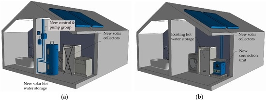
Figure 1.
(a) Conventional solar domestic hot water system, commonly featuring a solar storage with a heating coil at the bottom and an electric heater at the top; (b) Retrofitting the existing electric water heater by installing new solar collectors via a newly developed connection unit.
The principle of the presented retrofitted system is to reuse the existing hot water heater for solar hot water storage. The new solar collectors are connected to the existing storage by means of a recently developed connection unit containing the required balance of system (BOS) (Figure 1b). Consequently, the retrofitted solution upgrades the existing heating system instead of replacing it, which has the potential to reduce the investment cost in terms of both material and installation costs. The connection unit is designed to be non-invasively connected to an existing water heater of a conventional kind. In other words, there is no need to provide additional inlets or outlets in the hot water storage—the two available connections, inlet of cold water and outlet of hot water, are sufficient for installation of the module.
The retrofitted system aims to ensure the main operation modes of a solar hot water system: hot water discharge and solar charge. All components of the retrofitted system and the two operation modes are illustrated in Figure 2 and described in Table 1. The existing hot water heater is retrofitted to store solar heat at a variable temperature, while an additional small auxiliary storage with an electric heater is added in series to ensure that the required outlet temperature can be attained. The electric heater of the retrofitted storage (component #13 in Figure 2) is disconnected; this means that the retrofitted storage tank is now exclusively used for solar hot water at lower temperatures, which increases the collector working hours and efficiency [24].
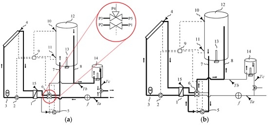
Figure 2.
Flow schematics and monitored measuring points during: (a) domestic hot water discharge and (b) solar charge.

Table 1.
Description of the components that comprise the entire retrofitted system.
During discharge (Figure 2a), when hot water is drawn off by the user, incoming cold water from the mains is preheated by the heat exchanger (when solar heat is available) before entering the bottom of the retrofitted storage. This forces the water at the top of the storage to flow into the bottom of the small heater and from there to the user. The auxiliary heater in the small storage tank is controlled by a thermostat and provides the extra energy when solar energy is insufficient.
During solar charge (Figure 2b), the pump on the solar circuit (#2 in the diagram) is turned on when the brine temperature from the solar collector (#4) is higher than the temperature at the bottom of the storage tank (#11). Subsequently, when the temperature on the heat exchanger (#15) becomes higher than the temperature at the bottom of the storage tank, the pump on the water side (#5) is also turned on. This makes cold water flow from the bottom of the retrofitted storage through the heat exchanger, where it is heated and flows into the top of the storage. Note that the direction of the water flow in the connections of the retrofitted storage (#7 and #8) is now reversed in comparison to the hot water discharge mode.
Having the larger storage working at lower temperatures reduces the retrofitted storage heat losses by approximately half [24]. Furthermore, mixing caused by diffusion and wall conduction is also considerably reduced, since the auxiliary hot water at 60 °C is not stored in the same tank as the cold water from the mains [24]. The temperature stratification of the system is therefore achieved by means of two tanks working at different average temperatures [24].
When a standard hot water heater is retrofitted for solar thermal use in a non-invasive manner, the two connections that were previously only used for hot water discharge to the user should now also be used to charge the storage with solar energy. As shown in Figure 2, each of the two connections of the retrofitted hot water heater need to be used in both directions to ensure favourable charge and discharge modes. A patented multiport valve was used to ensure the switch of operation modes, from hot water discharge to solar charge, and vice-versa, and is illustrated in Figure 2 and Figure 3. The multiport valve comprises five ports, two cavities and a sliding piston inside. Water does not run between the two cavities but the piston slides through them. During solar charge, the valve is in relaxed position and the water entering the valve in port P3 from the heat exchanger (#1) exits the valve from port P4 into the top of the retrofitted storage (Figure 2b and Figure 3a). During hot water discharge, incoming cold water flows into port P1 through the actuator and exits via port P2 (Figure 2a and Figure 3b). This pushes the piston and redirects the water entering the valve in port P3 coming from the heat exchanger to exit the valve from port P5 instead, into the bottom of the retrofitted storage. At this position, the illustrated magnet switches OFF the pump on the water side. Note that the spring illustrated in Figure 3c becomes compressed and forces the piston back to its relaxed/initial position once the hot water draught is over. The multiport valve therefore switches the operation modes of the retrofitted system in a mechanical way, which promotes long lifetime and reliability. A short video, Video S1, is attached to the electronic version of this article illustrating the behaviour of the multiport valve.
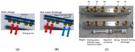
Figure 3.
Newly developed multiport valve [27]: (a) during solar charge; (b) during hot water discharge; (c) picture of the components of the valve while dismounted.
Technical drawings show that all the BOS components can be fitted together with an approximately 50-litre auxiliary storage in one connection unit with dimensions under 60 cm × 60 cm × 60 cm, as illustrated in Figure 1. The tested prototype seen in Figure 4 and Figure 5 was built at this stage without integrating the small auxiliary tank in the connection unit. This enabled the size of the auxiliary tank to be varied according to the size of the family.
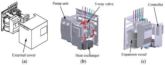
Figure 4.
Prototype drawings of the connecting unit excluding the auxiliary heater: (a) with the external cover; (b) without the external cover in perspective; (c) without the external cover in another perspective.
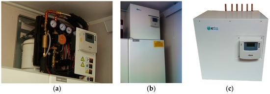
Figure 5.
Picture of the prototype: (a) without the external cover; (b) with the external cover; (c) showing the connections to: collector inlet, collector outlet, cold water main, domestic hot water supply to user, auxiliary heater inlet and outlet.
The evaluated installation, illustrated in Figure 5, retrofitted existing hot water storage of 300 L using approximately 5 m2 of flat plate solar collectors oriented towards south-east. The house is a direct-electrically heated villa situated in the south of Sweden where the average annual solar irradiation is approximately 1000 kWh/m2/year on a horizontal surface. The family comprises two adults and three teenagers.
3. Method
The thermal performance of a retrofitted solar domestic hot water system was measured over a full year. The model of the solar collectors was Vitosol 200-F with a total collector aperture area of 4.66 m2 manufactured by Viessmann [28]. The collectors were placed on a roof tilted 20° from horizontal facing south-east. The auxiliary heater storage was a Nibe Eminent with a volume of 35 L and an electric heater of 1 kW [29]. The retrofitted tank was a Nibe Compact with a volume of 300 L. The measurement points are shown in Figure 2. The temperatures were measured using PT 1000 sensors [30] and flow was measured using a Grundfos VFS flow meter [31]. The built-in Steca controller was used for controlling the operation of the system and for logging flow and temperatures [32]. Temperatures were measured as five-minute average values, and the flow was integrated during that period. An electric meter was installed in such a way that electricity use for the whole connecting unit and the auxiliary heater was measured together. The type of sensors is listed in Table 2.
Table 2.
Description of measurement equipment.
Domestic hot water is heated in two steps. Firstly, solar energy is used. The temperature difference over the solar (retrofitted) storage, , can be calculated to be (Figure 2a). This temperature increase includes the effects of the water passing the heat exchanger (#1). Secondly, auxiliary energy may be provided. The temperature difference over the small auxiliary heater, , can be calculated to be (Figure 2a).
The delivered energy from the solar installation, , and from the auxiliary tank, during one month can be calculated using Equations (1) and (2)
where is the flow, is the energy, is the density of water, is the specific heat for water and is the time. The sum is taken over all the five-minute time step values during the month.
The solar fraction over a certain period, , i.e., the fraction of the energy need that is covered by the solar installation in that period, can be calculated using Equation (3) [33].
All electrical energy consumption was measured over the full year. The measurement includes both the energy from the small auxiliary heater (#14) as well as the energy consumed by the pumps (#2 and #5) and the controller (#9) in the solar installation (Figure 2). This means that all electrical energy consumption is included in the measurements and calculations.
The life cycle cost (LCC) analysis was carried out by applying a geometric gradient series, which are cash flow series that either increase or decrease by a constant percentage for each period throughout the life cycle (see Equations (4)–(6)) [34]. The total LCC for the studied energy saving measures was summarized by applying Equation (7), and the life cycle profit (LCP) by applying Equation (8) [34]. The net present value for the domestic hot water consumption, , takes into account the annual running costs for domestic hot water production, , and how these costs are accounted over time by the influence of the rate of return on investment, , and a linear increase on the yearly electricity price, . Finally, the total net present value, , accounts for the net present value for the domestic hot water consumption, , together with the net present value for maintenance, , and the investment cost, . The meaning of each input and the considered assumptions are shown in Table 3. Since the result of an LCC analysis can be very dependent on certain assumed input parameters, a local sensitivity analysis was performed. This was carried out by varying the assumed input parameters by ±20% where the uncertainty was thought to be higher (Table 3). The LCP value was used to evaluate the impact of the sensitivity analysis and consists on the difference between the net present value with and without a solar domestic hot water system.
Table 3.
Description of the input parameters used in the life cycle calculations.
The International Energy Agency reports the investment cost for a solar domestic hot water system in Sweden, with a 5 m2 collector area and storage of 300 litres, to be approximately 5000 € excluding VAT [37]. The Swedish National Board of Housing, Building and Planning also reports on an average investment cost of a solar domestic hot water system in Sweden, including a new solar hot water storage, to be estimated at approximately 5000 € for a collector area between 4 m2 and 6 m2 [38]. In the neighbouring country of Denmark, such a system is reported to cost approximately 1100 €/m2 which would mean a total cost of about 5500 €/m2 for an entire system with 5 m2 solar collector area [12]. The total cost of a conventional solar domestic hot water system was set to 5000 € excluding VAT and 6250 € including VAT at 25%. The total cost of the retrofitted system was set to 3400 € excluding VAT and 4250 € including VAT, based on cost data from the manufacturing supplier for large volumes.
It is difficult to find detailed information on how the total investment cost is divided between the different parts of a solar domestic hot water system in Sweden. Based on the author’s experience and information from different sources, a cost distribution as illustrated in Figure 6 was assumed [38,39]. Note that the cost of the solar storage was set to zero for the retrofitted system since the existing hot water heater is reused.
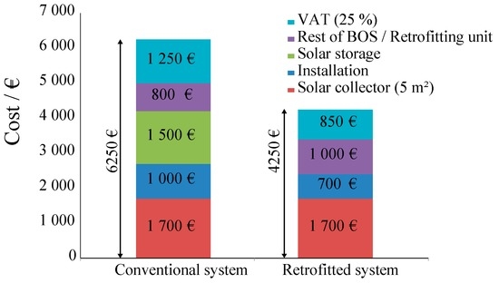
Figure 6.
Costs of the different parts of the conventional and retrofitted solar domestic hot water systems, including VAT.
The LCC calculations were based on an assumed life cycle of 25 years [12] and the residual value of the building and building materials was set to zero. An annual cost for covering maintenance such as replacement of the heat carrier fluid and pumps was set to 20 €/year for each of the systems. It was assumed that the existing domestic hot water heater was maintenance-free. No degradation rate for any of the systems was considered. The LCC calculations were performed for three cases: the retrofitted solar domestic hot water solution, a conventional solar domestic hot water system and the base case without any solar heating system. The results are compared in the next chapter.
The annual solar fraction for the conventional solar domestic hot water system was set to 50% as this is commonly reported in the climate where the study was conducted [24,38,40,41]. The solar fraction of the retrofitted solar domestic hot water system was measured and is reported in the next section.
4. Results
Figure 7 illustrates the measured monthly solar fraction of the retrofitted solar domestic hot water system. Values for January and February are missing since insufficient hot water was provided, forcing the users to turn on the auxiliary heater in the bottom of the retrofitted hot water boiler to a preheating temperature (#13 in Figure 2). During this period, solar energy savings could not be calculated, since the energy provided by the existing storage was a combination of energy from the electric heater and solar collectors. These two months were excluded from the energy savings because the system was not able to keep up with the demand. The annual energy needs and energy savings are presented in Table 4.
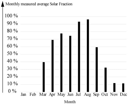
Figure 7.
Measured monthly solar fraction of the retrofitted solar domestic hot water system.
Table 4.
Measured annual values of the solar fraction and auxiliary energy need, and the corresponding calculated annual energy savings and energy need.
Figure 8 illustrates some of the measured temperatures and hot water discharge flow on 7 and 8 September, illustrating representative summer behaviour. During those days the incoming cold water temperature was approximately 16 °C. Once the temperature on the outlet of the solar collectors (#4), shown in yellow, was higher than that of the bottom of the tank (#11), shown in blue, the pumps started the charging process. It can be seen that stratification decreased initially, since water at a colder temperature was placed at the top. This is explained by the fact that the inlet position is placed at the top (Figure 2) while the controller compares the bottom temperature with the collector outlet temperature in order to start the pumps. At approximately 20:00 on the first day, hot water was discharged, which cools the bottom of the tank and builds up stratification. The discharge is shown in black using the right-hand vertical axis.
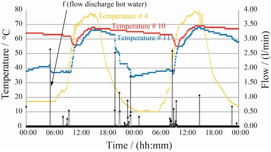
Figure 8.
Measured temperatures and flow of the retrofitted solar domestic hot water system on 7 and 8 September, illustrating representative summer behaviour.
Figure 9a shows the net present value during 25 years for three cases: base case (without solar energy), shown in blue; the retrofitted solar domestic hot water system, shown in red; and the conventional solar domestic hot water system, shown in green. With the assumptions applied, the payback time of the retrofitted system is approximately 17 years while the conventional system never becomes profitable. In Figure 9b the investment cost is compared to the life cycle profit after 25 years for each of the solar thermal systems. Only the retrofitted system is expected to reach any profit.
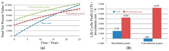
Figure 9.
(a) Life cycle cost based on net present value for the base case (without solar energy), retrofitted system, and a conventional solar domestic hot water system; (b) Life cycle profit (LCP) and investment cost for the retrofitted system and the conventional systems.
Figure 10 shows a sensitivity analysis of the LCP calculations by varying some of the assumed inputs by ±20%. The analysis shows that the result of the LCP calculation for the retrofitted system is always positive, but mainly negative for the conventional system. It can also be noted that the input parameters with the strongest influence on the LCP result are the cost of electricity, investment cost and lifetime.
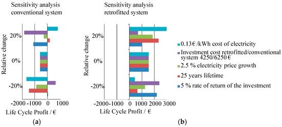
Figure 10.
Results of the sensitivity analysis on several input parameters regarding the life cycle profit for the (a) conventional solar domestic hot water system; and (b) retrofitted solar domestic hot water system.
5. Discussion
The estimated annual domestic hot water load of approximately 5000 kWh/year is roughly in accordance with the rule of thumb of 4500–4800 kWh/year mentioned by the Swedish Energy Agency for single-family houses [42]. If one follows measurements performed on domestic hot water consumption, the expected hot water load for a Swedish single-family house with five inhabitants would be 4000 kWh instead [43]. It is important to note that the measured load of 5000 kWh/year corresponds to gross consumption, i.e., including circulation losses. The measured annual solar fraction of nearly 50% is in line with previous theoretical estimations [24] and laboratory measurements [25], and the energy savings would be somewhat higher if energy production in January and February had been included. The collectors were placed on the same slope as a roof tilted 20° from horizontal facing south-east. At an optimal orientation of approximately 40° tilt from horizontal facing south, the annual received global solar radiation would increase approximately by 10% which would in turn increase the annual solar fraction.
The level of thermal comfort was, in this case, not sufficient in the winter during these months. This was expected from previous calculations for such a large family size in comparison with the size of the auxiliary heater (35 litres) [25]. Nevertheless, this was one of the aspects that were to be tested. The main ways to solve this problem are to either increase the volume of the auxiliary storage or to use the existing hot water storage for preheating in the winter [25]. In climates where solar radiation is more evenly distributed throughout the year, this challenge should be easier to overcome [25]. Since the added auxiliary storage ensures that the hot water load is met, even during winter, the more evenly distributed the solar radiation is throughout the year, the lower the required volume of the auxiliary storage becomes. Also, a higher level of annual solar radiation and higher ambient temperatures will naturally decrease the required collector area for the same annual energy production [25].
The recently developed valve generally behaved as expected, but further development and testing is required to ensure reliability and long lifetime. As illustrated in Figure 8, the control mechanism of the charging mode needs improvement in order to increase temperature stratification during charging.
In comparison with the base case without any solar heating system, the life cycle cost analysis showed no profitability for a conventional solar domestic hot water system and long payback time for the retrofitted solution. However, it is important to note that the cost analysis was carried out for Swedish conditions, which can be seen as a worst case scenario where electricity is cheap and the annual level of solar radiation is relatively low. The sensitivity analysis performed on some of the input parameters for the life cycle profit calculation did not show any single parameter that had a noticeably greater impact than the others; however, it did show that the results of the life cycle profit calculations are always positive for the retrofitted system but mainly negative for the conventional system.
Until 2011 there was a subsidy for solar thermal heating technology in Sweden [38]. The year subsidy was removed, the installation of new solar thermal collectors decreased to a third and continued decreasing thereafter at a slower rate [37]. One of the contributing factors is the profitability results shown in Figure 9a,b. The investigated retrofitted system has the potential to be more cost-effective if manufactured at larger volumes. In order to reach large production volumes, the retrofitted system needs to successfully get a market share in competition with other solutions for domestic hot water energy saving such as small air-to-water heat pumps which have recently entered into this specific market [44,45].
It is important to point out that the retrofitted system should only be considered in cases where the existing hot water storage is still estimated to have a long lifetime, or else the retrofitting may be pointless. The manufacturer of the most common brand of hot water heaters in Sweden claims that such storages have often long lifetimes, particularly if the electric heater, which is often a weak point, is not used [46]. The connection unit must be made more compact in order to simplify and reduce installation time. Technical drawings show that all components could be fitted in one connection unit with dimensions under 60 cm × 60 cm × 60 cm. Since most of the hot water heaters have base dimensions of 60 cm × 60 cm, the connection unit could be stacked on top of most hot water heaters, thereby further simplifying the installation.
The retrofitted solution is more dependent on the type of hot water storage and heating system and the domestic hot water load than the type of building itself. In this study, the retrofitted solar domestic hot water system was implemented by reusing the existing electric hot water storage for solar domestic hot water production. However, the same concept could also be applicable for storages using other energy sources as long as the hot water outlet is placed at the top and the cold water inlet at the bottom so that solar charge and hot water discharge are performed favourably, as illustrated in Figure 2. Such an example are pellets/wood hot water heaters which are almost as common as electric hot water heaters in Sweden [23]. In such case, the profitability is expected to decrease since pellets/wood is cheaper than electricity in Sweden. On the other hand, the house owner will benefit from long periods during the summer where refilling and cleaning the pellets/wood burner is not needed.
As it is designed today, the investigated retrofitted solar thermal system is not suitable for being installed in combination with a water-based space heating system. The main reason for this is that the capacity of the added auxiliary hot water storage is too small to cover the whole energy demand for both domestic hot water and space heating in the winter period. The heater placed at the bottom of the existing storage could be used for preheating but this would decrease the solar contribution and therefore the solar fraction. This is further discussed in [25]. When it comes to office buildings and multi-family houses in Sweden, these are commonly connected to district heating and therefore do not use heat storage. Hence, such retrofitting is not possible in this case.
6. Conclusions
A prototype of a retrofitted solar domestic hot water system was evaluated in a Swedish single-family house over one year. The retrofitting involved reusing the existing hot water heater to store solar heat when installing new solar collectors, to reduce the investment cost. The measured annual solar fraction was nearly 50% of the annual domestic hot water load of approximately 5000 kWh/year. This annual performance is comparable to that of conventional solar hot water systems. However, in this case, the level of thermal comfort, i.e., the capability to provide the required hot water temperature to the load, was, in this case, not sufficient in the winter. This can be solved by either increasing the volume of the auxiliary storage or turning on the existing hot water storage for preheating in the winter. The life cycle cost analysis showed that the retrofitted system is estimated to have a payback time of 17 years and a profit of approximately 1500 € after 25 years for an investment cost to the final customer of 4250 €. In contrast, a conventional solar hot water system did not show any profitability during its lifetime of 25 years for an investment cost to the final customer of 6250 €. The sensitivity analysis on some of the input parameters for the cost analysis showed that the result of the life cycle profit calculation is always positive for the retrofitted system but mainly negative for the conventional system.
Supplementary Files
Supplementary File 1Acknowledgments
Efficax Energy AB is acknowledged for closely collaborating in this study and providing the tested prototype [47]. The authors are thankful to the Swedish Energy Agency for co-funding this project [48]. Lund University is acknowledged for co-funding the publication fee for this investigation [49].
Author Contributions
This investigation is a continuation of Bernardo’s Ph.D. work. Both Luis Ricardo Bernardo and Henrik Davidsson were actively involved in the installation, monitoring and analysis of the results. Erik Andersson contributed during the installation of the prototype and monitoring measurements.
Conflicts of Interest
Both authors are researchers at Lund University and also co-founders of the company that designed the investigated prototype. The authors declare that this manuscript was written in a scientific and impartial manner.
References
- Buildings. Energy—European Commission. Available online: https://ec.europa.eu/energy/en/topics/energy-efficiency/buildings (accessed on 18 October 2016).
- Heating and Cooling. Energy—European Commission. Available online: https://ec.europa.eu/energy/en/topics/energy-efficiency/heating-and-cooling (accessed on 18 October 2016).
- 2020 Climate & Energy Package. European Commission. Available online: http://ec.europa.eu/clima/policies/strategies/2020/index_en.htm (accessed on 18 October 2016).
- Werner, W.; Biermayr, P. Potential of Solar Thermal in Europe; 2020 Climate & Energy Package—European Commission; EU-Funded Project RESTMAC, Sixth Framework Project; European Solar Thermal Industry Federation Federation (ESTIF): Brussels, Belgium, 2009. [Google Scholar]
- Østergaard, P.A.; Lund, H. A renewable energy system in Frederikshavn using low-temperature geothermal energy for district heating. Appl. Energy 2011, 88, 479–487. [Google Scholar] [CrossRef]
- Østergaard, P.A. Wind power integration in Aalborg Municipality using compression heat pumps and geothermal absorption heat pumps. Energy 2013, 49, 502–508. [Google Scholar] [CrossRef]
- Rad, F.M.; Fung, A.S. Solar community heating and cooling system with borehole thermal energy storage—Review of systems. Renew. Sustain. Energy Rev. 2016, 60, 1550–1561. [Google Scholar] [CrossRef]
- Zhang, X.; Shen, J.; Adkins, D.; Yang, T.; Tang, L.; Zhao, X.; He, W.; Xu, P.; Liu, C.; Luo, H. The early design stage for building renovation with a novel loop-heat-pipe based solar thermal facade (LHP-STF) heat pump water heating system: Techno-economic analysis in three European climates. Energy Convers. Manag. 2015, 106, 964–986. [Google Scholar] [CrossRef]
- Gill, L.; Mac Mahon, J.; Ryan, K. The performance of an evacuated tube solar hot water system in a domestic house throughout a year in a northern maritime climate (Dublin). Sol. Energy 2016, 137, 261–272. [Google Scholar] [CrossRef]
- Zambrana-Vasquez, D.; Aranda-Usón, A.; Zabalza-Bribián, I.; Jañez, A.; Llera-Sastresa, E.; Hernandez, P.; Arrizabalaga, E. Environmental assessment of domestic solar hot water systems: A case study in residential and hotel buildings. J. Clean. Prod. 2015, 88, 29–42. [Google Scholar] [CrossRef]
- Masson, G.; Brunisholz, M. Trends 2015—In Photovoltaic Applications—Executive Summary; Report IEA-PVPS T1-27:2015; International Energy Agency (IEA): Paris, France, 2015. [Google Scholar]
- Mauthner, F.; Weiss, W.; Spörk-Dür, M. Solar Heat Worldwide—Markets and Contribution to the Energy Supply 2014; IEA Solar Heating & Cooling Programme and AEE—Institute for Sustainable Technologies: Gleisdorf, Austria, 2016. [Google Scholar]
- Beerepoot, M.; Tam, C.; Philibert, C.; Frankl, P. Technology Roadmap: Solar Heating and Cooling; International Energy Agency (IEA): Paris, France, 2012. [Google Scholar]
- Hang, Y.; Qu, M.; Zhao, F. Economic and environmental life cycle analysis of solar hot water systems in the United States. Energy Build. 2012, 45, 181–188. [Google Scholar] [CrossRef]
- Tsilingiris, P.T. World Renewable Energy Congress Renewable Energy, Energy Efficiency and the EnvironmentDesign and performance of large low-cost solar water heating systems. Renew. Energy 1996, 9, 617–621. [Google Scholar] [CrossRef]
- IEA SHC||Task 54. Available online: http://task54.iea-shc.org/ (accessed on 18 August 2016).
- Homepage Conergy. Available online: http://www.conergy.com.au/ (accessed on 18 August 2016).
- Thermo Dynamics Ltd. Solar Water Heating—Solar Pumps. Available online: http://www.thermo-dynamics.com/ (accessed on 18 August 2016).
- Manager, S.B.G. Enerworks. Available online: http://enerworks.com/ (accessed on 18 August 2016).
- Trachte, S.; Deherde, A. Advanced and Sustainable Housing—A Guide for Designers and Planners; IEA Solar Heating and Cooling Programme; International Energy Agency (IEA): Paris, France, 2010. [Google Scholar]
- Mondol, J.D.; Smyth, M. Comparative Performance Analysis of Solar Heat Exchangers for Solar Hot Water Systems. In Proceedings of the EuroSun 2012, Rijeka, Croatia, 18–20 September 2012.
- Baechler, M.; Gilbride, T.; Ruiz, K.; Steward, H. High-Performance Home Technologies: Solar Thermal & Photovoltaic Systems; Building America Best Practices Series; U.S. Department of Energy: Washington, DC, USA, 2007; Volume 6.
- Swedish Energy Agency. Energy Statistics for Single-Dwelling Buildings in 2014; ES 2015:04; Swedish Energy Agency: Stockholm, Sweden, 2015. [Google Scholar]
- Bernardo, L.R.; Davidsson, H.; Karlsson, B. Retrofitting Domestic Hot Water Heaters for Solar Water Heating Systems in Single-Family Houses in a Cold Climate: A Theoretical Analysis. Energies 2012, 5, 4110–4131. [Google Scholar] [CrossRef]
- Bernardo, L.R. Retrofitting Conventional Electric Domestic Hot Water Heaters to Solar Water Heating Systems in Single-Family Houses—Model Validation and Optimization. Energies 2013, 6, 953–972. [Google Scholar] [CrossRef]
- Fjaestad, A.; Persson, H.; Holmén, A. Two out of Three Showers for Free. In Proceedings of the 11th IEA Heat Pump Conference, Montréal, QC, Canada, 12–16 May 2014.
- Bernardo, R.; Davidsson, H.; Larsson, S. System, Module and Valve for Domestic Hot Water Heaters. Patent Number PCT/SE2013/000121, 2 July 2015. [Google Scholar]
- Viessmann Vitosol 200-F Flat Plate Solar Collector. Available online: http://www.viessmann.ca/en/residential/solar/flatplate-collectors/vitosol_200-f.html#93f6a39f1e956f5924d66cb36de73162 (accessed on 19 August 2016).
- NIBE EMINENT Hot Water Heater. Available online: http://www.nibe.se/produkter/varmvattenberedare/NIBE-EMINENT/ (accessed on 19 August 2016).
- PT1000 Temperature Sensor. Available online: http://www.thermometricscorp.com/pt1000 (accessed on 19 August 2016).
- Grundfos VFS Flow Meter. Available online: http://www.grundfos.com/content/dam/Global%20Site/direct-sensors/Direct_Sensors_Flow_Databooklet.pdf (accessed on 19 August 2016).
- Steca TR 0603. Available online: http://www.steca.com/index.php?Steca-TR-0603mc-plus-en#producttechnicaldata (accessed on 19 August 2016).
- Buckles, W.E.; Klein, S.A. Analysis of solar domestic hot water heaters. Sol. Energy 1980, 25, 417–424. [Google Scholar] [CrossRef]
- Blank, L.; Tarquin, A. Engineering Economy, 7th ed.; McGraw-Hill Education: New York, NY, USA, 2011. [Google Scholar]
- Lindahl, J. National Survey Report of PV Power Applications in Sweden; Uppsala University and International Energy Agency: Uppsala, Sweden, 2014. [Google Scholar]
- Gustafsson, M.; Kruså, M. Life-Cycle Cost (LCC)-Project Instructions; Statens Fastighetesverk: Stockholm, Sweden, 2014. [Google Scholar]
- IEA-Solar Heating and Cooling Programme—Country Report—Sweden. 2016. Available online: http://www.iea-shc.org/country-report-sweden (accessed on 19 August 2016).
- Sjöberg, P.; Johansson, P.; Borgecrona, Y.; Carlsson, A.; Hedenmo, M. Evaluation of the Solar Heating Subsidy; 2012:9; The Swedish National Board of Housing, Building and Planning: Karlskrona, Sweden, 2012.
- Costs of Solar Heating Systems. Available online: http://www.svensksolenergi.se/fakta-om-solenergi/fragor-och-svar/solvaerme-kostnader (accessed on 19 August 2016).
- Hobbi, A.; Siddiqui, K. Optimal design of a forced circulation solar water heating system for a residential unit in cold climate using TRNSYS. Sol. Energy 2009, 83, 700–714. [Google Scholar] [CrossRef]
- List of Solar Domestic Hot Water Heating Systems. Available online: http://www.sp.se/sv/index/services/solar/water/list/Sidor/default.aspx (accessed on 19 August 2016).
- Stengård, L.; Hellberg, C. Water Use in Dwellings; ER 2012:03; The Swedish Energy Agency: Eskilstuna, Sweden, 2012. [Google Scholar]
- Stengård, L. Measurements of Cold and Hot Water Use in 44 Dwellings; ER2009:26; The Swedish Energy Agency: Eskilstuna, Sweden, 2009. [Google Scholar]
- Vieira, A.S.; Stewart, R.A.; Beal, C.D. Air source heat pump water heaters in residential buildings in Australia: Identification of key performance parameters. Energy Build. 2015, 91, 148–162. [Google Scholar] [CrossRef]
- Heat Pump Water Heaters|Department of Energy. Available online: http://energy.gov/energysaver/heat-pump-water-heaters (accessed on 19 August 2016).
- NIBE—Energy Systems. Available online: http://www.nibe.eu/ (accessed on 19 August 2016).
- Efficax Energy. We Connect the Sun Directly to the Heater. Available online: http://efficaxenergy.com/en/ (accessed on 19 August 2016).
- The Swedish Energy Agency. Available online: http://www.energimyndigheten.se/ (accessed on 19 August 2016).
- Lund University. Available online: http://www.lu.se/ (accessed on 19 August 2016).
© 2016 by the authors; licensee MDPI, Basel, Switzerland. This article is an open access article distributed under the terms and conditions of the Creative Commons Attribution (CC-BY) license (http://creativecommons.org/licenses/by/4.0/).