1. Introduction
Electric vehicles (EVs) offer an effective transportation solution to reduce fuel consumption and greenhouse gas emissions [
1,
2,
3]. Chemical batteries are the primary energy storage method used, with various lithium-ion chemistries dominating the market due to their energy density, safety, and cost [
4]. However, the issues of battery capacity degradation and vehicle range anxiety restrict the promotion and widespread market penetration of electric vehicles [
5]. These two topics are linked because the battery capacity degradation reduces the vehicle range over its lifetime.
For lithium-ion batteries, the degradation rate increases at high current rates [
6] and at temperature extremes. Extreme temperatures also restrict battery power and it is preferable to operate the batteries within a controlled temperature range, for example 0–40 °C [
7]. Thermal control systems are included in vehicles to manage battery temperatures in extreme ambient or driving conditions. In order to meet the vehicle power requirements, the battery pack design may be dominated by power requirements rather than energy storage. This can lead to different cell or chemistry selection, or adding more cells, which can worsen the battery balancing problem [
8]. Vehicle driving patterns require frequent charging and discharging during acceleration and braking [
9], often under extreme temperatures. These high-power operations seriously reduce the battery lifespan [
10].
To mitigate these issues, a supercapacitor (SC) can be combined with the battery to create a hybrid energy storage system (HESS) [
11]. These two kinds of power sources have their individual advantages: the SC has longer lifespan, higher power density and wider working temperature range [
12,
13,
14] to deal with high power transients [
15]. The battery can store energy on a large scale and supply sufficient energy for the trip. According to previous reports, the first feature of the HESS is the protection of the battery during high power situations [
11]. Secondly, making good use of the high discharging efficiency of SC could decrease the total energy loss in a HESS [
13]. Thirdly, because of the physical characteristics, the SC is more suitable for working in an extreme ambient environment. Equally, the SC is helpful to alleviate the battery degradation rate effectively under aggressive driving situations [
15]. Fourthly, since the SC can store the regenerative braking energy, the lithium battery is able to avoid frequent charging [
14,
16]. Taking advantage of the high discharging efficiency of SCs can also decrease the total energy loss in HESS.
This paper addresses the sizing of the SC to mitigate battery degradation while minimizing cost and size of the additional components. The control strategy and battery degradation models are critical components of this problem. Previous work has quantified the battery capacity loss according to SC size. Odeim et al. researched the power management between SC and battery by using a genetic algorithm and Pareto front analysis in a framework of multi-objective optimization [
17]. Blanes et al. proposed a FPGA controlled interleaved bidirectional converter which is smaller than the common DC/DC converter to prolong battery life combined with SC [
18]. Song et al. replaced the bi-directional DC/DC converter with un-directional DC/DC converter and added a diode into the topology to minimize the system cost. The paper also quantifies the battery capacity loss by using different SC sizes [
12]. As to the battery decay estimation, recent studies have shown many kinds of battery degradation prediction models [
6,
19,
20,
21,
22]. The demanded power, which consist of the combination of driver behaviors, auxiliary power needs, vehicle specifications, ambient temperature, is regarded as the main factor that influences the battery degradation rate. For batteries, the current value and cumulative charge are the direct elements that influence the degradation process. Carter et al. illustrated improved lead-acid battery life by using SC [
23]. Wang et al. addressed empirical formulas which contain calendar and cycle degradation by summarizing large scale experiment data [
6,
22]. Besides individual research on battery degradation, some other literatures analyze battery capacity loss by using SCs [
13,
24,
25]. Omar et al. used electrical-double layer capacitors to enhance battery energy efficiency and voltage performance, rather than increase the vehicle range [
24]. A lithium-ion battery increases the lifespan about 30% to 40% in the proposed topology. Chen et al. quantified the LiFePO
4 battery cycle life when the vehicle is running under different discharging current rates with a battery/SC semi-active structure [
25]. Shen et al. considered cycle life degradation on the urban dynamometer driving cycle (UDDS) and used the dividing rectangles (DIRECT) algorithm to evaluate the configuration between battery and SC [
13]. However, as to the lithium-ion battery and SC configuration, there is no authoritative theory on size matching between these two power sources [
26]. The main contribution of this paper is a simple metric and method to evaluate the power and energy requirements of various drive cycles, and from that derive an appropriate capacitor size. This metric is termed the continuous power-energy (CPE) function. Rather than run a complete multi-objective optimization with simultaneous optimization of hardware and controller, this method allows a rapid estimate for an appropriate capacitor size. We justify the use of this method by considering all possible capacitor sizes, calculating their best-case performance using a controller with a priori knowledge, and demonstrating that the CPE method estimates a capacitor size similar to that determined by a full optimization. The purpose of this article is to develop a systematic approach to configure the HESS size and evaluate LiFePO
4 battery lifespan improvement under different load profiles. Compared with the previous studies, the features of the paper may be listed as the following:
- (a)
Previous studies only considered the integral of total demanded power, neglecting the power contribution of the battery operating with constant power output. This paper calculates the integral of power difference between the power and power threshold. The proposed CPE function is an integral function to compare the cumulative demanded power for electric vehicles.
- (b)
During HESS configuration, previous studies just considered the total driving cycle rather than individual driving phases. This article combines the driving cycles and individual driving phases together.
- (c)
The previous papers fail to compare the battery life improvement with the ideal potential on mitigating battery degradation. This paper evaluates the battery degradation mitigation compared to the best-case controller using a priori knowledge.
- (d)
The previous references failed to quantify battery degradation during different driving cycles. This paper quantifies the battery degradation in different driving cycles, especially for the mild and aggressive cycles.
2. Calculating Power and Energy Requirement
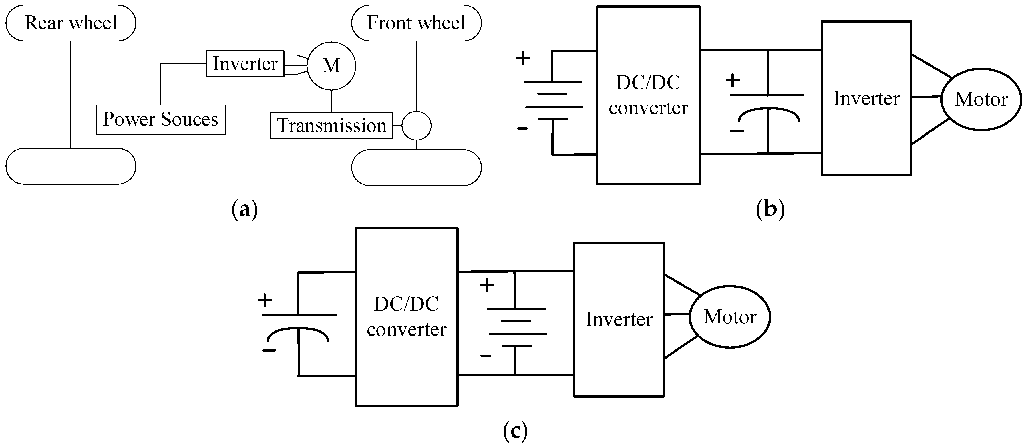
The overall component diagram of the electric vehicle is shown in
Figure 1. For the battery only diagram, the power source is a battery. As to the HESS diagram, the vehicular power source comprises a SC, battery and DC/DC converter. There are many kinds of HESS topologies, such as the battery/SC and SC/battery diagram, semi-active, fully active and multiply input converter topology [
12,
27]. Except for DC/DC cost, the effects of battery protection in battery/SC and SC/battery topologies among the above topologies are similar. Since the purpose of the article is to verify the novel HESS configuration method, this paper does not consider the DC/DC cost. As to the adopted topology, considering that: (1) the SC has higher efficiency to retrieve regenerative braking energy; (2) batteries should avoid frequent charging actions; (3) battery life is more sensitive to the driving cycle than the SC, the harmonic effect to the battery should be decreased as much as possible, therefore, the battery/SC structure is chosen as the HESS topology in this paper.
2.1. Energy Calculation
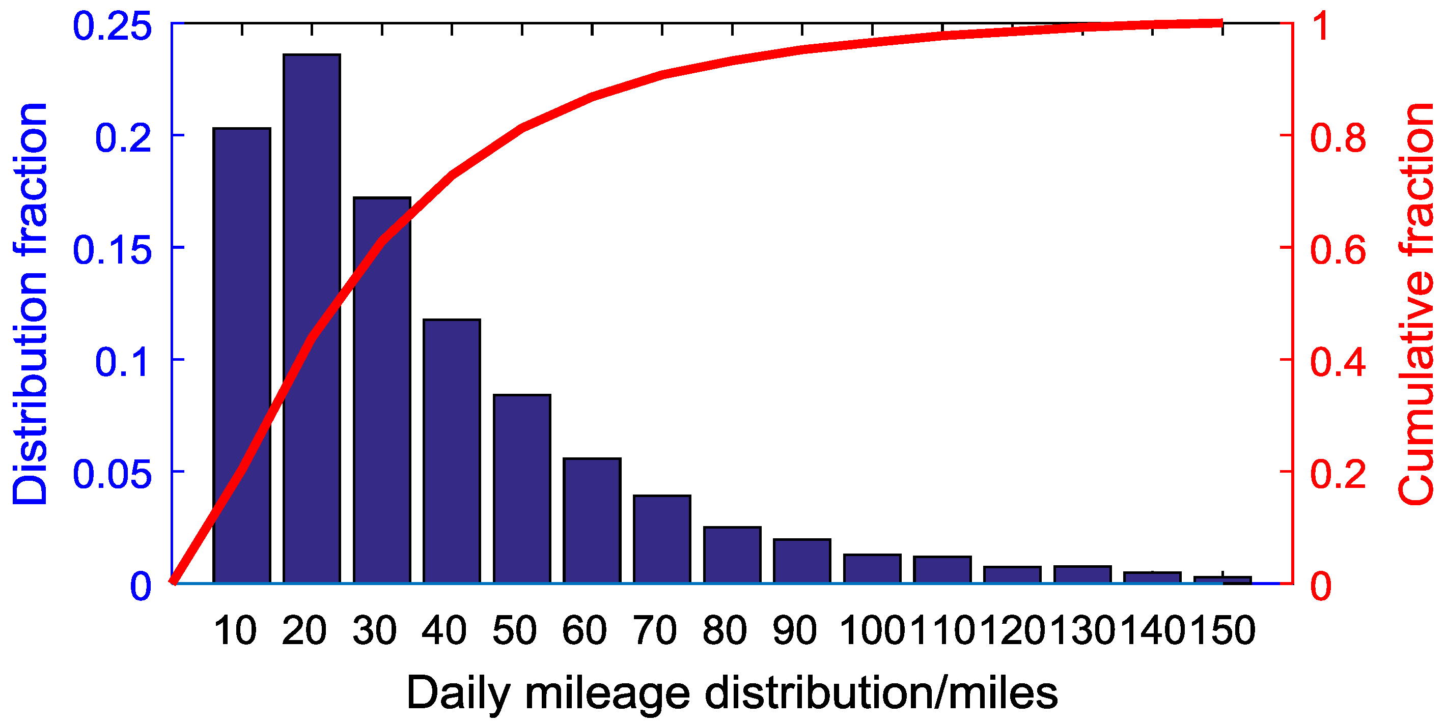
Table 1 lists the statistical data of the daily mileage according to the national household travel survey (NHTS) database. Most (80%) of the vehicles drive less than 51 miles (82 km) per day. Sixty miles (96.6 km) range can satisfy 85% of the total drivers.
Figure 2 gives the daily driving range distribution and cumulative mile range, respectively. For most drivers, the daily range is focused on short distances [
28]. In general, electric vehicles are appropriate for the majority of drivers.
The average driving distance for all statistical vehicles is 35 miles per day. According to the prior research [
29,
30,
31,
32,
33,
34,
35], the battery must be replaced for vehicle applications once the battery capacity is reduced to70%-80% of the original rated capacity (20%–30% degradation). In reality, since many drivers just drive vehicles within limited miles, the definition of battery lifespan is not appropriate for all vehicles [
36]. However, for the purpose of evaluating the battery degradation, this paper adopts the definition that the battery is retired once the capacity decreases 30% compared with the original capacity. Referring to the NHTS statistical information, the energy source should be configured to satisfy 85% of the vehicles. These two factors mean that the vehicle range at the end of life is at least 60 miles (96.6 km). Since energy capacity fading is a more limiting factor governing retirement than power fading, this paper considers the energy degradation as the battery degradation index [
36].
According to the previous literature [
37,
38,
39,
40], there are many factors that influence the battery degradation, including the auxiliaries, tire types, powertrain efficiency, ambient temperatures, velocity and terrain. The tire type and powertrain efficiency are determined by the vehicle properties. The auxiliaries, velocity, terrain and temperature can contribute to the demanded power, which is the connection bridge between the battery degradation and vehicle properties. During driving, the demanded power is determined by the driver behavior. By converting the vehicle properties to demanded power, most of the above factors can be simplified on a certain vehicle and driving cycle. This paper simplifies these factors and uses the driving behaviors to analyze the battery degradation. Under the same ambient environment, aggressive driving usually leads to larger battery degradation than mild driving for the same driving distance. According to the energy consumption of a Nissan Leaf measured by Argonne National Laboratory (ANL, Lemont, IL, USA) at room temperature [
41], the average energy consumption rate is 173 Wh/mile (107 Wh/km, UDDS) and 276 Wh/mile (171.4 Wh/km, US06).
In this study, a vehicle energy consumption model is created. Except for power sources, this paper adopts the same components as a Nissan Leaf in the vehicle model [
42,
43]. In order to cover 85% of the statistical daily distance requirement (60 miles) at the end of life (70% capacity remaining), the usable energy should be no less than 10.38 kWh in UDDS. The original energy configuration should be higher than 14.83 kWh. If the driving cycle is US06, the usable energy of HESS should be more than 16.56 kWh, while the configured energy should be at least 23.66 kWh. Owing to different driving behaviors, HESS is configured by using the higher energy consumption driving behavior (US06), so 23.66 kWh is selected as the total energy requirement for HESS.
2.2. Power Calculation
For the same driving distance, different driving behaviors lead to different energy consumption patterns. This paper considers two kinds of driving styles: mild (UDDS) and aggressive (US06) styles. According to ANL measurement data, the vehicular power distribution is shown in
Table 2. 1 CP is defined as the power value at which battery could discharge all energy in 1 h. For an EV equipped with a 24 kWh battery, 1 CP = 24 kW. Since the energy density of a SC is much smaller than that of a battery, this paper assumes all energy is stored in a lithium-ion battery.
As to driving cycle, the UDDS and HWFET are the common driving cycles which are adopted by the U.S. Environmental Protection Agency (EPA) to estimate the fuel economy of vehicles. This paper also adopts the UDDS and HWFET as basic cycles to calculate the demanded power. The UDDS represents city driving or mild driving behavior, and its demanded power is smooth. US06 represents an aggressive driving style. The high power usage accounts for a larger percentage in US06 than in UDDS and HWFET. According to the control strategy, the battery supplies the basic demanded power while the SC acts as assistant power when the demanded power is high. In a theoretical case, when the SC size is infinite in the battery/SC structure, the battery can discharge on the constant average power.
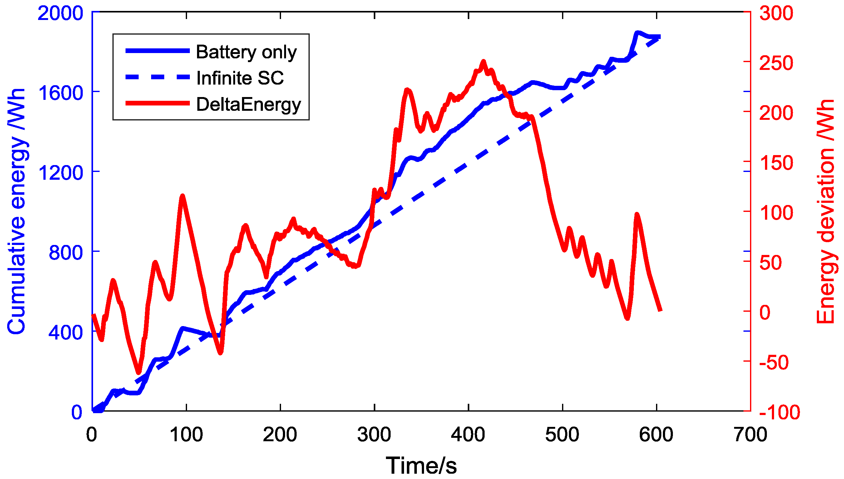
Figure 3 shows the cumulative energy used on the cycle, calculated by integrating the road power. This is the energy the battery would deliver if it was the only energy storage. This case is compared to a vehicle with a large capacitor, which allows the battery to discharge at constant power yet deliver the same total energy. The difference between the two is the energy deviation that must be stored in the capacitor. In order to realize the ideal effect like an infinite SC case, the energy deviation stored in the SC will be as high as 300 Wh on a single US06 cycle (
Figure 3). Here, we assume the powertrain efficiency of driving is 85%, and the recovery efficiency of the regenerative braking efficiency is 20%. The “battery only” case is the cumulative energy used on the cycle, calculated by integrating the road power. The hybrid battery-SC vehicle with a very large SC allows the battery to discharge at constant power (dashed blue line) yet deliver the same total energy. The difference between the two is the net energy that must be stored in the capacitor (red solid line). According to [
44,
45], the average cost of a SC is 10,000–15,000 $/kWh. Large capacitors are cost prohibitive.
3. Configuration of the Power Sources Using the Continuous Power-Energy (CPE) Function
In this study, the model type of battery is the VL45E LiFePO
4. The SC is a BCAP 2000 SC from Maxwell Technology [
13].
3.1. Calculate the Maximum Power for HESS
The factors influencing the maximum current for a battery and SC are different. For the battery, degradation is the main factor which limits the maximum discharging current. In order to protect the battery, the allowed maximum discharging current for battery cell should be smaller than 3 C [
46]. In this paper, the maximum charging/discharging current for battery is set as 3 C. For the purpose of mitigating battery degradation, the battery current should be controlled as low as possible.
For the SC, the efficiency is the main reason which constrains the maximum power value. As to discharging/charging parameter limitations, the calculation process is as follows:
where, η
SC refers to the SC efficiency; OCV
SC represents the open-circuit voltage;
is the current; and R
SC is the internal resistance. This study sets the lowest limit for efficiency as 0.9 when calculating the current limit of SC during charging/discharging process. This is shown in Equation (2):
where,
IlimitD and
IlimitC represent the current limits of SC when discharging/charging, respectively. Using the terminal voltage and current limits for charging/discharging, the power limit of the SC during charging/discharging could be calculated using Equation (3):
where,
PSClimitD and
PSClimitC represent the power limit of the SC during discharging/charging, respectively. According to Equation (3), the maximum discharging current/power for each SC cell is 771 A/1875 W, the maximum charging current/power for each SC cell is 857 A/2571 W.
Different from a chemical battery, a SC stores energy in physical characteristic. When an SC is used as power source, theoretically 100% of the energy can be delivered [
27]. However, considering the security and protection of the SC, the discharging action should be terminated once the voltage is below half the maximum voltage [
47]:
When the voltage of SC is equal to
,
SOC of SC is 0.25. The total usable energy for a SC cell is [
18,
47]:
Table 3 lists battery and SC cell parameters.
3.2. CPE Function
HESS performance refers to the ability to satisfy the power demand, which is determined by the individual performance parameters, including energy capacity and charging/discharging limits of the battery and SC packs. The great difference in power and energy performance between batteries and SCs results in two problems during application: (i) difficulty in determining an appropriate method to evaluate the performance characteristics of HESS; (ii) difficulty in establishing a clear relationship between the performance of batteries and SCs. Consequently, it is difficult to determine HESS component size. To address these issues, this paper proposes the concept of continuous power-energy (CPE) function. The following four conditions are used to determine whether HESS could satisfy the power requirement:
I.
Prequired (demanded power) should be less than the sum of power limits
PBATlimit (battery power) and
PSClimit (super-capacitor power), which is:
II. SCs should satisfy any power demand that exceeds the power limits of battery. However,
PSC (power required by SCs) cannot exceed E
SC (energy capacity of SCs), which is:
III. The energy required for the entire process when charging/discharging should be smaller than the sum of the energy capacity of
EBAT and
ESC, which is:
In order to simplify to the above equations, the concept of PE function is introduced. The function is defined as Equation (9):
where,
P refers to the demarcation power (kW).
E is the energy consumption (kWh), which represents the integral value of the power versus time when power demand is greater than
P. The details are shown in Equation (10):
where,
P(
t) is the power-demand function in terms of time (unit: kW). This function is known as the PE function. Equations (6)–(8) can be rewritten using this function as follows:
IV. In previous studies, the SC is configured based on total driving cycles [
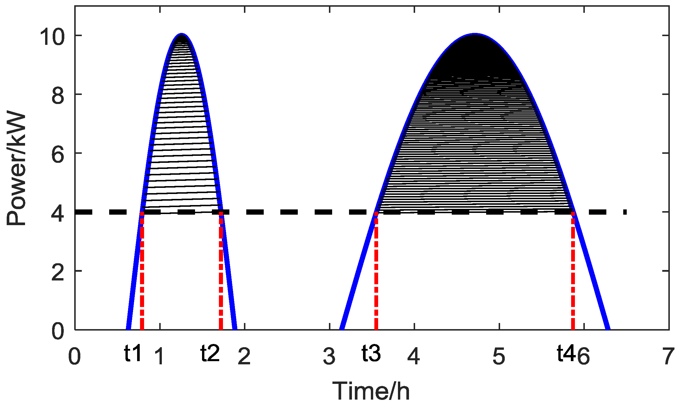
13]. Considering the special features of a SC in a HESS whereby the SC could discharge and charge quickly, a continuous discharging part could be used to configure SC. This paper considers the situation that SC should meet required energy in an independent continuous action. In a total trip, calculate
for every continuous segment, and choose the maximum
. Referring to
Figure 4, supposing
is 4 kW, calculate every continuous segment which is higher than
(shadow area), finally, choose the maximum
as
. Therefore:
3.3. SC Configuration for HESS
The CPE function is used to calculate the maximum continuous cumulative energy when the demanded power is higher than a constant battery power value during driving. A SC has lower energy and higher power density than a battery. As to the low demanded power area, the battery should supply the energy, while in a high demanded power situation, the SC should assist the battery by supplying the excess power. The problems are how to make sure the appropriate CPE function and the demarcation power point. In order to use this CPE concept to size an effective SC, we must understand how to select the demarcation power point and how it relates to the CPE maximum energy. Next we consider the combination of driving cycles and special driving phases to find the largest energy consumption in this research.
3.3.1. Driving Cycle Analysis
As to the driving cycles, the UDDS and HWFET are the common driving cycles which are adopted by the U.S. EPA to estimate the fuel economy. In this study, CPE results are calculated on these two driving cycles which represent common driving situations.
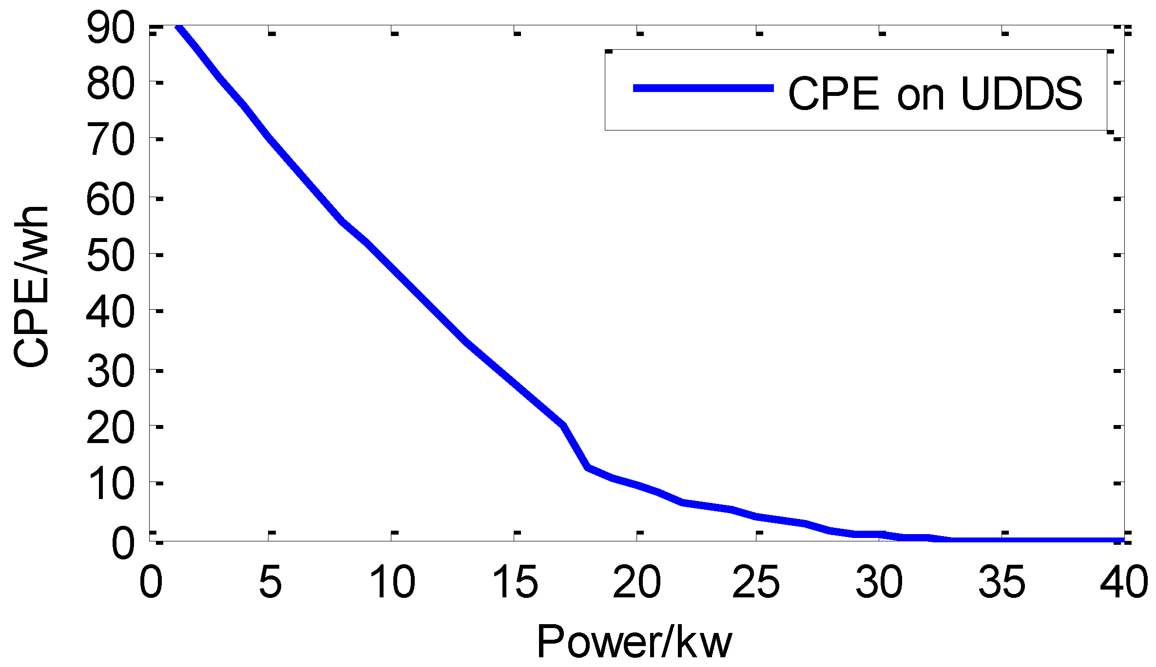
The CPE function results for UDDS and HWFET are shown in
Figure 5 and
Figure 6. On the blue curve, the horizontal axis represents the battery power limit, and the vertical axis is the lower limit of the SC size. In these two cycles, most of power is focused in the low power area. The red line in
Figure 7 represents the larger CPE value at every power point combining these two cycles.
The northeast area above the red curve is the appropriate area for SC configuration to ensure sufficient energy capacity.
3.3.2. Specific Driving Phase Analysis
In a HESS, the SC acts as an assisted power source which aids the battery instantaneously. Besides driving cycles, specific driving phases should also be considered during CPE calculations. During daily driving, a large power requirement occurs frequently in the starting and acceleration periods.
(i) Start-Up Phase
When the EV is driven in the city, the vehicle has to stop and start repeatedly. The model sample used in this study should have the ability to start up after halting for 60 s and then speed up to 30 mph.
Figure 8 shows the velocity and demanded power curve during start-up. The corresponding CPE function is shown in
Figure 9. Both figures reflect the speed, demanded power and CPE itinerary. On the blue curve, the horizontal axis represents the battery power limit, and the vertical axis is the lower limit of the SC size.
(ii) Acceleration Phase
The vehicle requires the motor to supply high power during acceleration. The sample vehicle model in this study is required to accelerate from 0 to 50 mph within 20 s. Just like the figures in the start-up phase, the power demand and CPE function in acceleration mode (as shown in
Figure 10) can be used to determine the SC size in a HESS. The area above the blue curve is the configuration range for the SC in
Figure 11.
Combining the staring up and acceleration phases, the CPE function results are shown in
Figure 12. Compared with the starting up phase, the acceleration phase from 0 to 50 mph plays a dominant role. The red dashed curve is the maximum value between the black and green curves. The northeast area above the red curve is the appropriate area for SC configuration.
3.3.3. Calculate the HESS Component Size
Combining the above two common driving cycles and two special driving phases, the final CPE results are shown in
Figure 13. The red dashed line represents the largest CPE function among the four situations.
Corresponding to
Figure 13, the dark circles which represents the CPE function results are listed in
Table 4. Different
could lead to different
values. As
becomes larger, the
value decreases.
To ensure the
is appropriate, the power distribution in driving cycles should be analyzed. For the common driving cycles (UDDS and HWFET), the demanded power distribution is calculated in
Table 5.
The power demarcation point should cover most of the daily driving power requirements. The UDDS and HWFET represent the most commonly used driving cycles, and the majority (61.2%) of the driving power is located in the range of 0–0.2 CP. This paper adopts 0.2 CP as the battery power demarcation point. The number of SC cells could be calculated as follows:
The number of SC cells is chosen as 76. According to Equation (3), the maximum discharging power for SC package is 142.5 kW, which is as high as 5.9 CP. This power threshold is large enough to cover most of the driving power needs in daily driving. Considering the regenerative energy efficiency of the motor, the discharging power of the HESS is higher than the maximum charging power of the vehicle from the regenerative braking. As the maximum allowable discharging power is lower than the maximum allowable charging power for SC according to Equation (3), this paper just considers the discharging situation for HESS.
As to battery configuration, the essential energy from battery should be:
The number of battery cells should be:
where,
represents the rated energy of battery cell.
refers to the needed rated capacity of the battery package.
Considering the topology of battery cells, the number of battery cells should be configured as 164. The HESS diagram is shown in
Figure 14.
As to the energy consumption calculation, it is not easy to create an accurate model since a large numbers of factors influence the energy consumption, so it will be very useful if a reference or similar true vehicle were measured. According to [
25], for similar vehicles, there is an energy consumption relationship between different vehicles. For model, the total energy consumption can be calculated approximately as:
where,
refers to fuel economy for HESS model,
refers to the weight of HESS which contains a DC/DC converter, battery package and SCs [
25].
represents the battery package weight on the Nissan Leaf.
represents the weight of common components between the model and the Leaf.
refers to the fuel economy of the Leaf which is measured by ANL.
Table 6 is the component weight comparison between the model and Leaf.
According to Equation (21), the fuel economy of the model and Leaf are very close. In theory, the deviation between these two models is 0.12%, so this paper uses the Leaf demanded power measured by ANL on different driving cycles to represent the model demanded power.
4. Control Strategy
The SC is used to compensate the demanded power once the power is higher than the battery power threshold [
17]. The diagram of the control strategy is shown in
Figure 15. In the control strategy, action B represents a case where the battery has to discharge at a high current rate while the SC does not have enough energy to assist the battery. Action B is harmful to battery life and should be avoided. In contrast, actions C and E could reduce the frequency of occurrence of action B. As to control strategy,
Pmin is the key factor which balances the charging and discharging of the capacitor. If the
Pmin is too large, the SC cannot minimize the battery degradation as much as possible; while if
Pmin is too small, the frequency of occurrence of action B would increase because of the limited SC capacity, which is also not good for mitigating battery degradation. In this paper, the average power of UDDS is chosen as the
Pmin.
Pmin should be close to the average power demand for the trip. If not, the energy flowing between the battery and SC could lead to additional consumption which increases the battery loss.
In order to assist the battery as much as possible, this study adopts sectional functions to charge the SC in actions A, B and C, which is different from the previous research on SC control as listed in in Equations (22) and (23), which is not able to deal with different driving cycles [
23,
48]:
where,
is the expected
SOC of SC,
refers to the vehicle velocity,
is the expected SC voltage,
is the maximum SC voltage. In this study,
Vmax is defined as 2.7 V per SC cell or 205.2 V for a pack of 76 SCs. For the control strategy in this paper, the
is set 0.75. For the control strategy, the details are as follows:
Actions A and B: the usable SOC range of SC is from 25% to 100%. Once the SOC is higher than 50%, the SC could supply all needed power (Preq − Pmin). When the SOC is lower than 50%, the SC just supplies a certain percentage of the total needed power (Preq − Pmin).
Actions C and D: When the required power is less than Pmin, the battery will supply all required power to the motor. Furthermore, the battery also charges the SC if the SC SOC is lower than 50%. As to the charging current, it equals the min (sectional value, Current limitation-Current required). Current limitation represents the maximum allowable discharging current of a battery. Current required represents the demanded current for the motor. Sectional value represents the charging current from the battery to the SC. If the SC SOC is less than 50%, the sectional value is 0.5 C; if the SC SOC is in the range [0.50, 1], the sectional value is 0.2 C. With these two driving situations, the control strategy will guarantee the SC has enough energy stored to assist the battery in the next peak power requirement situation.
Action E: Battery could charge the SC when the SC SOC is lower than SOCexp. During range [SOCexp, 1], the regenerative energy will charge the SC.
This control strategy could help the SC adapt different kinds of driving behaviors. Once the vehicle demanded power is low, the battery will charge the SC to a certain SOC level. Though the situation that two peak power demand cases may appear, the time interval between them should be long enough to recharge the SC for the next big power demand. Besides, the probability of two continuous peak power demand cases is also small. For the SC, the charging time is very short (just 1–10 s) [
45]. The target of the proposed control method is to cover the majority of driving situations, so the aforementioned situation of two continuous big peak power situations is not considered in this paper because of the low probability of occurrence.
5. Battery Degradation Model
According to [
22], battery degradation is divided into two parts: calendar life loss and cycle life loss. Calendar life loss is a function which is related to the temperature and time, while the cycle life loss is related to current rate, cumulative current and temperature. In the research, the following equations are used to calculate the battery degradation [
49]:
where
and
are pre-exponential factors,
T is the absolute temperature,
a/
b/
c/
d/
e are fitted from curve,
is the current C rate,
represents the amount of charge delivered by the battery during cycling,
T is the days,
is the activation energy in J·mol
−1, and
R is the gas constant. These parameters values are listed in the
Table 7.
The calendar degradation portion is almost the same for different structures or topologies. In this paper, the battery package temperature is assumed as room temperature (293 K). The cycle degradation part is the exact portion which is influenced by the SC.
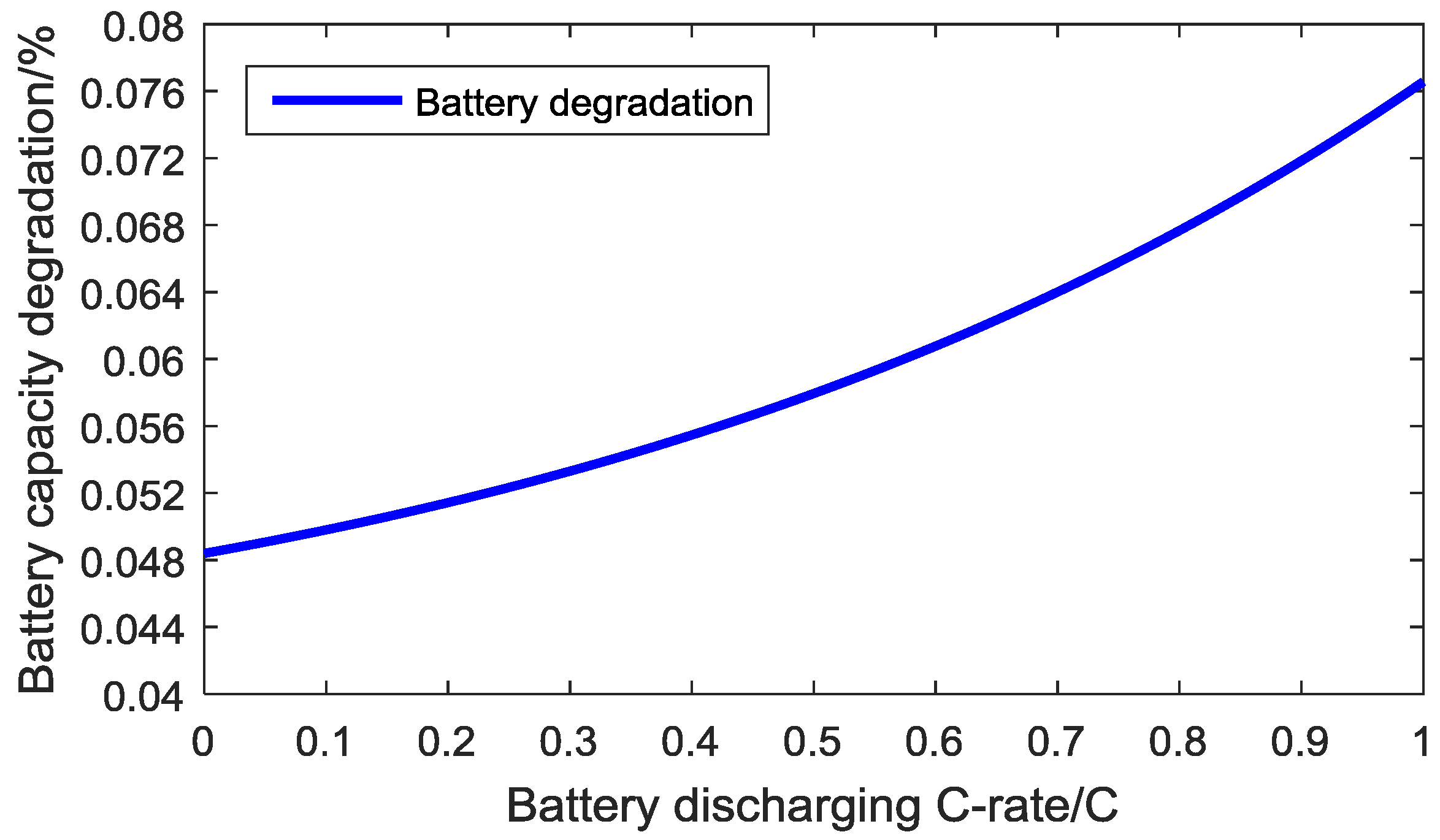
According to Equation (24), the battery cycle loss rate is related to the discharging rate and total integral of the current. In terms of energy, since the battery density is much higher than that of the SC, the lithium-ion battery is the main energy source in HESS. However, in terms of power, the SC plays a significant role in power supply, and the SC can reduce the battery current when the demanded power is high.
The energy flow between battery and SC leads to energy consumption. However, except for regenerative braking, all SC energy is transferred from the battery. This paper supposes the efficiency of the DC/DC converter is 95% [
50], and the coulombic efficiency of the SC is 92% [
51]. Considering the DC/DC converter and SC consumption, the cumulative discharging energy from the battery will increase as the discharging current rate threshold of the battery decreases. For example, supposing the battery capacity is 100 Ah, and the demanded current is 1 C (100 A):
- (1)
When the battery discharging threshold of the current rate is 1 C (100 A), the battery will discharge 100 Ah (neglecting the battery consumption);
- (2)
When the battery discharging threshold of the current rate is 0.4 C (40 A, which is smaller than the demanded current), in order to protect the battery, the SC will supply the other demanded current portion (0.6 C). Compared to situation I and neglecting the energy from regenerative braking, all energy discharged from the SC originates completely from the battery and will experience DC/DC converter and SC consumption, so the total energy flow from battery is: , which exceeds 100 Ah.
Though the low current rate threshold is good for battery life, the cumulative current discharged from the battery becomes larger, which is harmful for battery life according to Equation (24), so there is a mathematical contradiction between the battery current limitation and the cumulative current when discharging.
Considering the DC/DC converter and SC efficiency,
Figure 16 shows the relative battery degradation value for different discharging current rate thresholds and combines the contradictory effects of lower battery currents implying more total energy use. Battery degradation rate increases with the battery current increasing. In the meantime, it shows that the degradation slope becomes larger as the discharging current increases. The conclusion could be reached that the battery discharging current
has a heavier weight in battery degradation than
. To decrease the battery current value could be an effective method to prolong the battery life. In the control strategy, the target of the SC is to reduce the battery discharging current. The ideal case is that the battery could discharge at constant average power.
6. Simulation Results
The following
Figure 17,
Figure 18,
Figure 19,
Figure 20 and
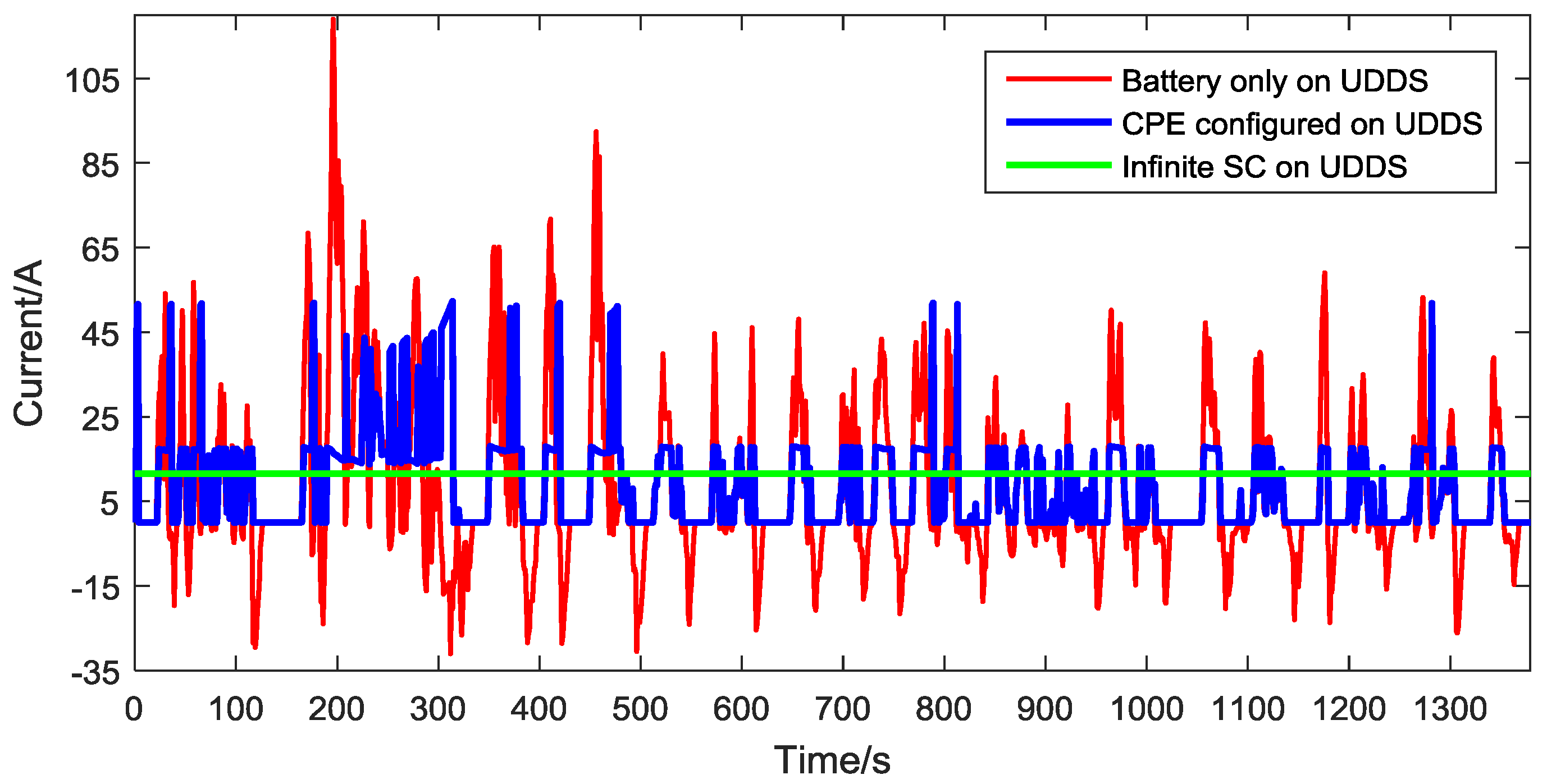
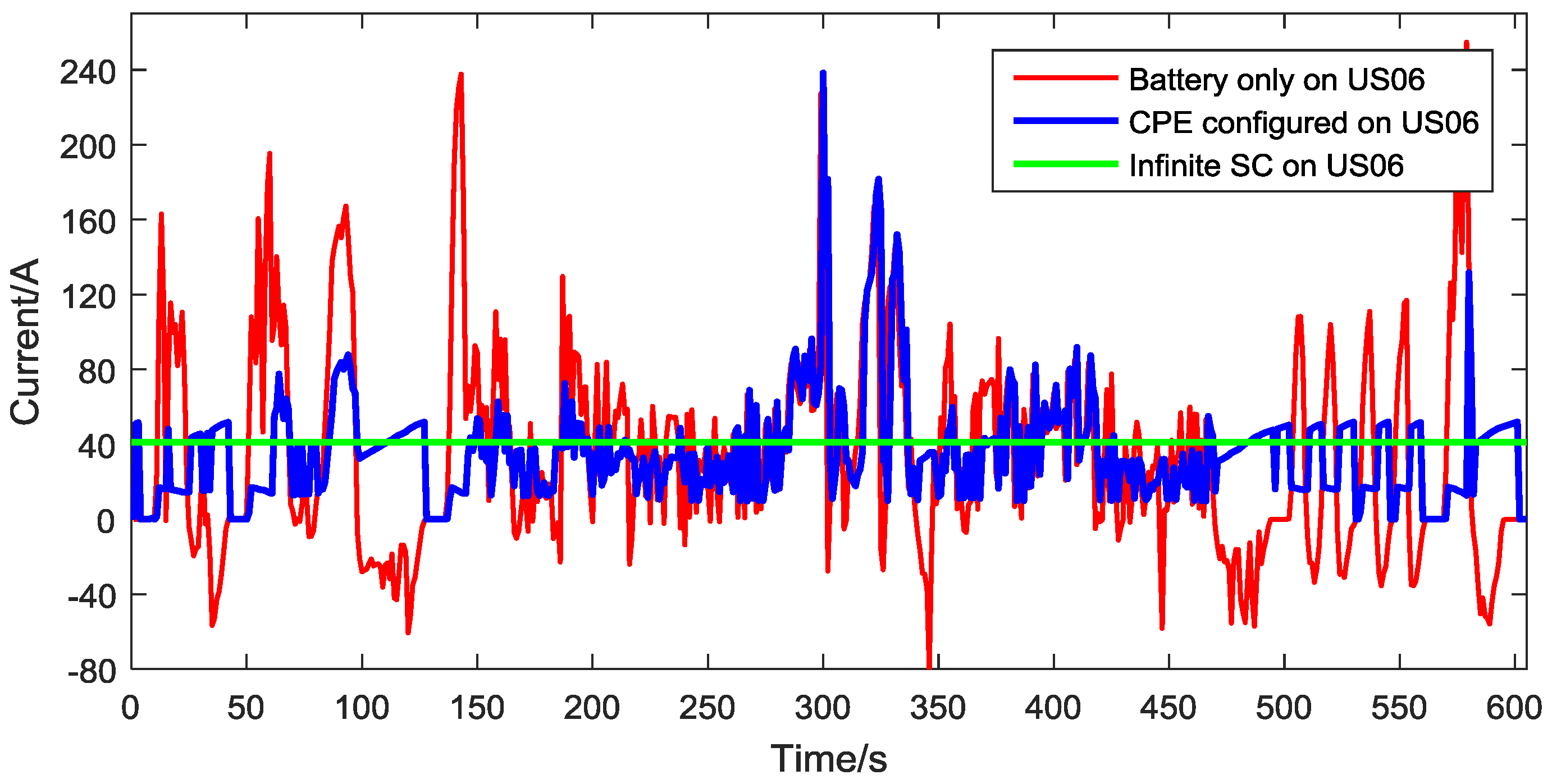
Figure 21 compare the battery currents used for a vehicle with a battery only, a HESS system with the capacitor configured based on the CPE, and an ideal HESS with infinite SC. The battery only type refers to the structure that the power source of EV is a single battery package. The CPE configured type represents the HESS structure which consists of a battery and SC sized based on the CPE method. Finally, the infinite SC type represents the ideal case where the battery current can be strictly controlled to the average current. The infinite SC type does not exist in reality, but provide a useful benchmark. After simulation, battery results for different driving cycles are listed as follows:
Figure 17 and
Figure 18 show that the compound power sources receive all regenerative braking energy, and it can eliminate the peak current area effectively compared with the battery only structure.
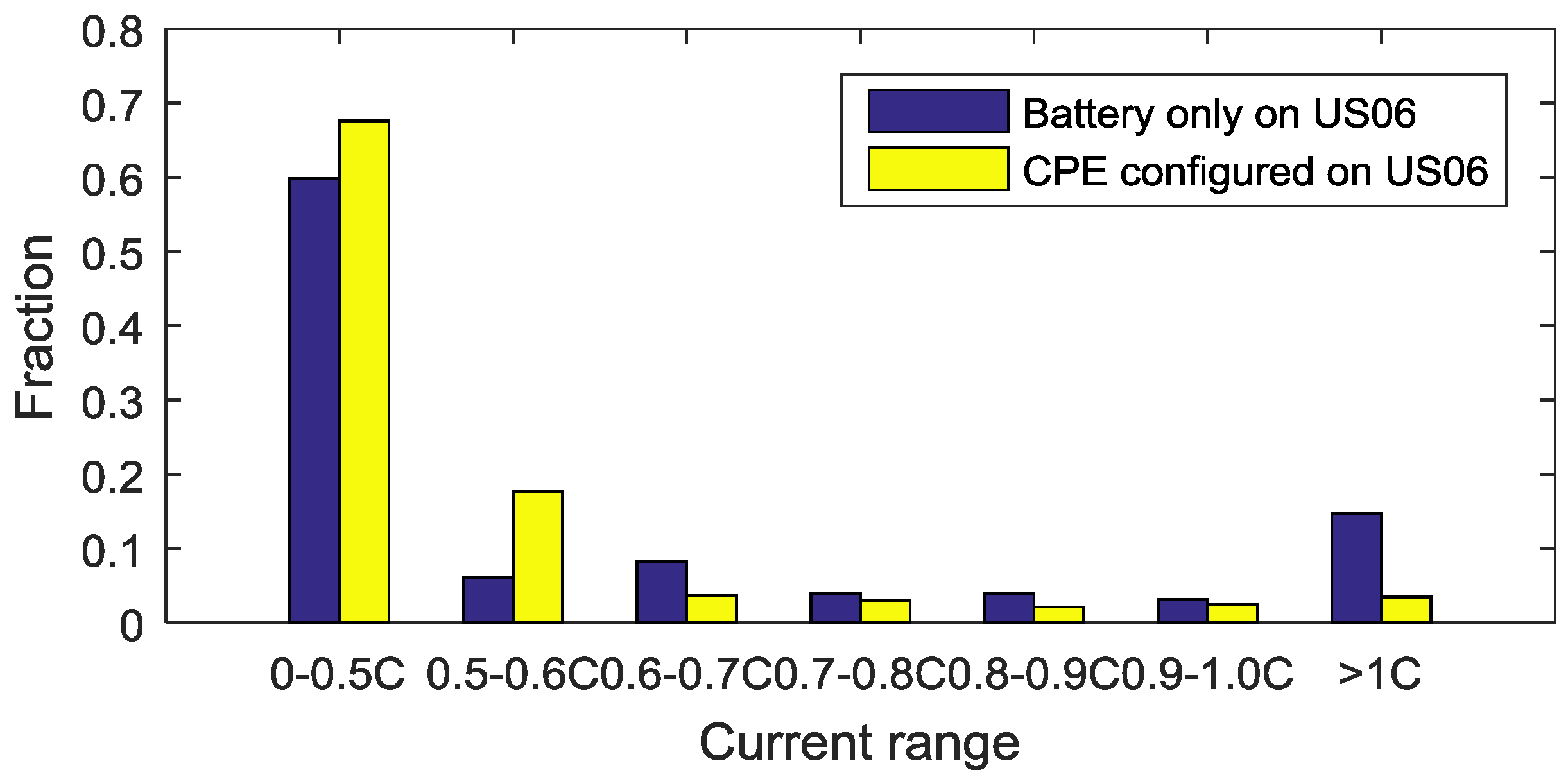
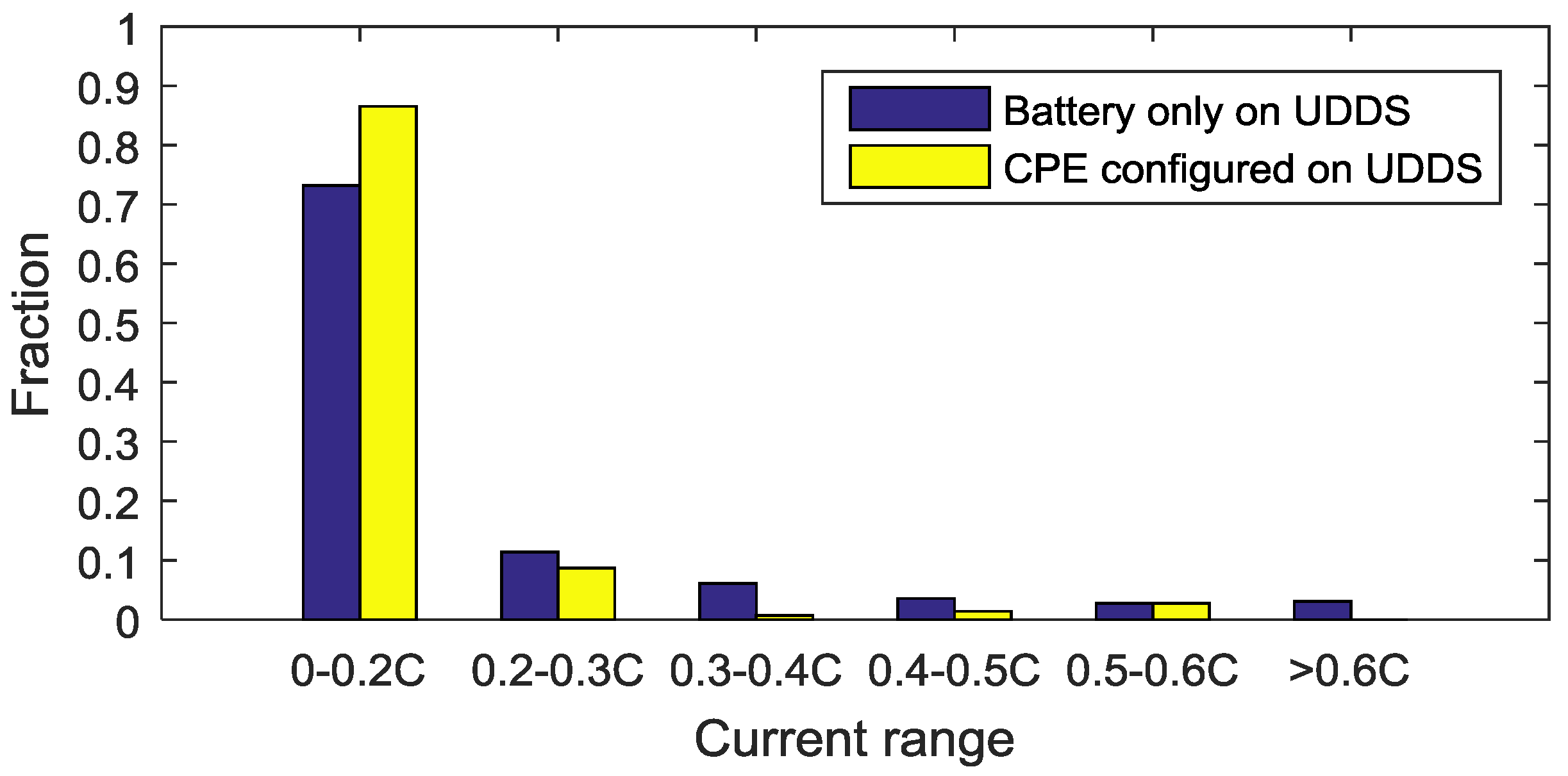
Figure 19 and
Figure 20 are the battery current distribution histogram, where the high current percentage becomes much lower while the low battery current area percentage becomes higher. These phenomena indicate that the battery discharging current rate has decreased, which prolongs battery life.
As to daily driving distance in the simulation, since the average driving distance is 35 miles (56 km), this paper uses the same driving distance to simulate UDDS and US06. The cumulative degradation for 10 years is shown in
Table 8, which contains the battery degradation results on different driving cycles with the above control strategy and configuration.
For a mild driving style like UDDS, the influence of SC on mitigating battery degradation is effective. After 10 years, a CPE configured structure could mitigate the battery degradation from 43.3% to 35.7%. For the infinite SC case, the battery degradation could be mitigated from 43.3% to 35.1%. The battery mitigation percent comparing the battery alone case is given by:
Converting to the mitigation percentage based on the battery alone case, the CPE configuration realizes the result that it mitigates 17.55% of the battery degradation. Equally, comparing the battery alone case, 17.55% of the primary battery degradation could be mitigated by using the CPE-configured capacitor. Using the same method, 18.94% of the primary battery degradation is mitigated in an infinite SC case.
In terms of the realization percentage, compared to the battery alone case, the CPE-configured structure realizes 92.68% of the maximum battery mitigation:
For US06, which represents the aggressive driving behavior, the CPE-configured structure could mitigate 21.6% of the battery degradation compared to the battery degradation in the battery only structure after 10 years. For an infinite SC case, the largest mitigation of battery degradation is 26.08% in this case. The CPE-configured battery/SC structure realizes 82.82% of the maximum battery mitigation.
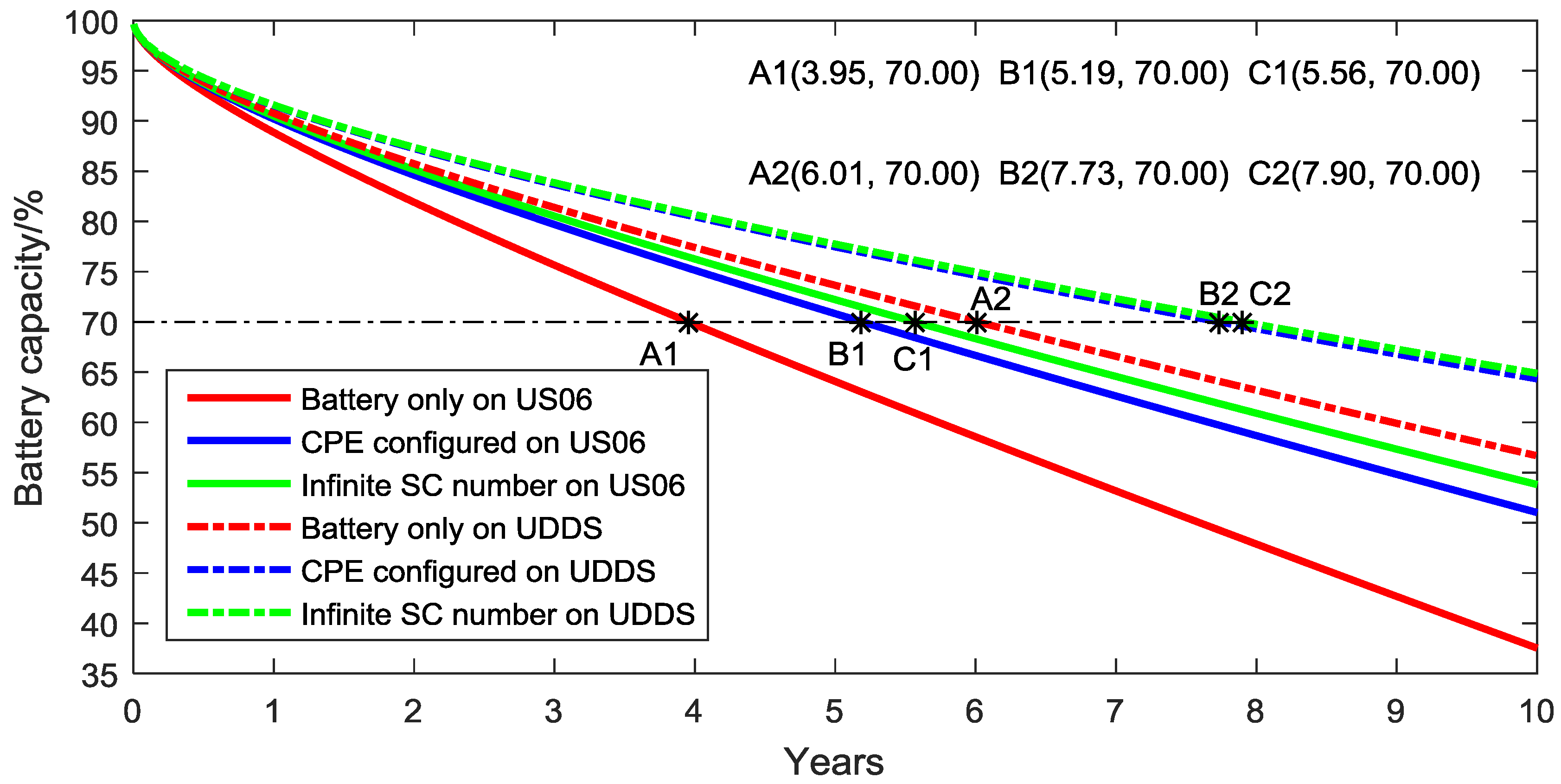
Considering the concept of battery life that the battery should be replaced in the vehicle once the remaining capacity reaches 70%,
Figure 21 shows the simulation results of battery life span in different structures and driving cycles. For UDDS, the CPE-configured case could prolong battery life 28.62% compared with the battery only case:
Similarly, for the infinite SC case, it can prolong battery life 31.45% which represents the maximum potential for prolonging battery life. Based on the previous calculation, the CPE-configured structure realizes 91.01% of the maximum potential on prolonging battery life:
For US06, the CPE-configured case can prolong battery life 31.39%, while the infinite SC case could prolong battery life 40.76%. The CPE-configured structure realizes 77.02% of the maximum potential on prolonging battery life. After 30% capacity fade, the remaining capacity of the battery is 16.56 kWh, which could still drive the vehicle for up to 60 miles under the US06 regime. According to the results, the current CPE configuration method could be effective in mitigating battery degradation for both mild and aggressive driving behaviors.
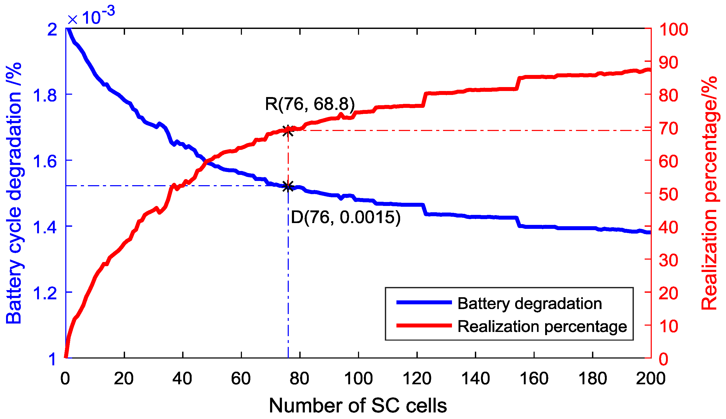
Since the SC size is configured by the CPE function based on the UDDS and HWFET, it can meet the power demand well in these mild driving cycles. However, in the other kinds of driving cycles, especially the aggressive driving cycles, we would like to confirm that CPE provides an effective method to size the SC. In order to explore the relationship between battery degradation mitigation and SC size, we consider a different cycle, US06, with many possible SC sizes. For each possible size, an optimization algorithm with
a priori future knowledge of the cycle selects the power flow to minimize the battery degradation. This limit represents the best possible performance of any controller on that cycle, with that particular SC size. This gives us a baseline that is independent of controller design, and provides a quantitative relative benefit of increasing SC size. Designers can use this curve to understand tradeoffs between SC size and performance. The results are shown in
Figure 22.
Using the 76-cell SC size configured by the CPE function can decrease the battery degradation from 0.002% to 0.0015%, realizing 68.8% of the potential reduction in cycle degradation. This is a reasonable design point to select, as larger SC size starts to provide diminishing returns. It could be realized that the battery capacity loss can be reduced rapidly when the SC cells increases in the range of 0–76. After that, the degradation curve becomes smooth. The CPE function could get the SC size demarcation point in the HESS configuration.
7. Conclusions
This paper introduced a systematic configuration method for the battery and supercapacitor in electric vehicles. According to the National Household Travel Survey data and the Argonne lab dynamometer data, the total HESS energy size can be configured to meet the cumulative energy demand. A continuous power-energy function is proposed to calculate the total cumulative energy which is used to assist the battery during continuous driving action. Combining common driving cycles (UDDS and HWFET) and special phases (start-up and acceleration), the continuous power-energy result is used to size the supercapacitor in the HESS. After the hybrid energy storage system configuration, the discharging process of the system is simulated and battery degradation is quantified for different driving behaviors (mild and aggressive). In terms of the battery degradation comparison after 10 years, the continuous power-energy configured battery/supercapacitor topology realizes 92.68% and 82.82% of the largest mitigation in UDDS and US06, respectively. In terms of prolonging the battery life, the continuous power-energy configured battery/supercapacitor topology realizes 91.01% and 77.02% of the largest possible mitigation under UDDS and US06 conditions, respectively. The simulation results verify the developed continuous power-energy configured approach serves as an effective procedure to configure the hybrid energy storage system and decrease battery degradation for electric vehicles adopting supercapacitors as an assisted power source.


 ,
, 


