Article

Study on the Optimum Design Method of Heat Source Systems with Heat Storage Using a Genetic Algorithm

Department of Architectural Engineering, Pusan National University, 2 Busandaehak-ro 63, Geomjeong-gu, Busan 609-735, Korea
*
Author to whom correspondence should be addressed.
Energies 2016, 9(10), 849; https://doi.org/10.3390/en9100849
Submission received: 1 August 2016 / Revised: 20 September 2016 / Accepted: 6 October 2016 / Published: 21 October 2016
(This article belongs to the Special Issue Energy Conservation in Infrastructures 2016)

Abstract

:
Recently, a heat source system utilizing a heat storage tank for energy savings in buildings was designed. A heat storage tank is an effective system for solving the qualitative and quantitative differences in the required building energy. On the other hand, the existing design process of a heat storage system is difficult to determine if the air-conditioning time is unclear, and the design in a real-working level is too inaccurate, causing oversizing and a high initial investment cost. This results in inefficient operation despite the introduction of an efficient system. Therefore, this study proposes an optimal design method of a heat source system using a thermal storage tank. To demonstrate the usefulness of the proposed design method, feasibility studies were conducted with the existing system designs. As a result, the optimal solution could reduce the initial cost by approximately 25.6% when following the conventional design process and it was approximately 40% lower than the real-working method. In conclusion, the conventional designs are inefficiently over-designed and the optimal design solution is superior. In this regard, the suggested optimal design method is efficient when designing a heat source system using a thermal storage tank.

1. Introduction

According to the reports of the International Energy Agency (IEA) and Energy Information Administration (EIA) in 2015 [1,2], the world’s total energy consumption has been increasing from 1971 to 2013 and buildings consume more than 30% of the global energy. These trends have highlighted the social needs of energy savings and environment protection and many researchers have developed high-efficiency technologies for buildings. Among them, the heat storage system is an effective way of improving the efficiency of heating and cooling systems [3].
A heat storage system solves the temporal, quantitative, and qualitative gaps that may appear between supply and demand of thermal energy, and helps improve efficiency by supplying advanced and centralized energy to the load-side. In particular, it is useful for renewable heat sources, such as solar energy systems, which produce different amounts of heat energy depending on the weather conditions and has a huge time gap between production and consumption [4]. In addition, district heating systems also need to store the thermal energy produced to help cope with the demand.
In buildings, the use of a heat storage system is more effective for load leveling of the heat source if the building load is concentrated. In particular, it has a huge effect when the building is under peak load at a particular time because it can reduce the capacity of the heat source systems significantly. On the other hand, it is difficult to reduce the capacity of buildings, such as hotels and hospitals, because it is important to have a reliable air conditioning system. Instead, these can make the heat source system idle through the use of a heat storage tank as a buffer station. In addition, it can save operation costs with a heat storage system by utilizing the electricity tariff effectively, which is called “nighttime electricity service” offered from the Korea Electric Power Corporation [5]. The building can take advantage of the low rates if a building operates systems to store heat and power during the night for the next day load. Furthermore, according to the tariff of electricity offered from the Korea Electric Power Corporation, the electricity price is classified according to the load time (light, medium, heavy) and season.
On the other hand, enormous design variables are generated to use energy efficiently by applying not only a heat storage system, but also many design elements, such as renewable heat sources, complex system combinations, and multiple unit application. Accordingly, the design process becomes increasingly more complex to optimize. Even if considering only a heat storage system, the initial construction costs would be increased by the storage tank and control system. Moreover, heat losses occur by the difference between the heat storage and heat rejection time highlighting the need for an optimal design and strategy for energy efficient and economical operation.
Many studies of the heat storage systems on the heat storage materials and storage methods have been carried out, such as ice storage system, thermally activated building system, and using phase change material (PCM) [6,7,8]. In addition, several studies on the economic and efficient design method have been carried out in recent years. Yu et al. [9] examined the design capacity of a heat storage system through cases and derived the best combination considering the system performance and energy consumption. As for optimization using an algorithm, Sun et al. [10] reviewed the optimal operation method of a heat storage system, particularly for peak load shifting. According to the manuscript, the method can be configured according to the type of thermal storage system, such as the thermally activated building system or using PCM. Despite that, most studies focused on the day for optimization; hence, it is necessary to consider a more extended period of time for the design days. Ikeda and Ooka [11] examined the optimal operation method of an energy storage system and suggested the economic optimal operation in accordance with the rates. In the United Kingdom, a study of the optimal design and operation of the system combined with a storage tank was conducted for district heating by considering three standard electricity tariffs. On the other hand, there is a limit on the decision of the system capacities at a constant value [12]. Shirazi et al. [13] optimized the ice thermal energy storage system considering the compressor ratio and temperature as the design parameter and the optimal solution could improve both the exergetic efficiency and total costs. Wu et al. [14] evaluated an optimal system combination, including a thermal storage system considering the size of each system, operation schedule and pipelines to establish an energy network. They considered several system combinations for a case study but the design parameters of each system were limited. Unlike previous studies performed on the optimization of a thermal storage system, it was insufficient according to the decision of the system capacity in the design process. For more optimization in design and operation, it is necessary to develop an optimal design method including capacity decision.
In this study, to propose the optimal design method of the heat source system including a thermal storage tank, the conventional design process of a thermal storage system was considered and an optimal method was developed utilizing a genetic algorithm. The optimization process of this study integrates a variety of input data, such as weather conditions, building, heat sources, system efficiency, economy, and operational conditions. In this paper, an optimization model is constructed based on the iSIGHT (Dassault Systèms Simulia Corp., Providence, RI, USA) tool to validate the proposed method and the optimization results are developed according to the representative load patterns of the daytime, nighttime, and 24 h to evaluate the usefulness of the method. In addition, a feasibility study was carried out with the conventional designs.

2. Optimum Design Process of Thermal Storage System

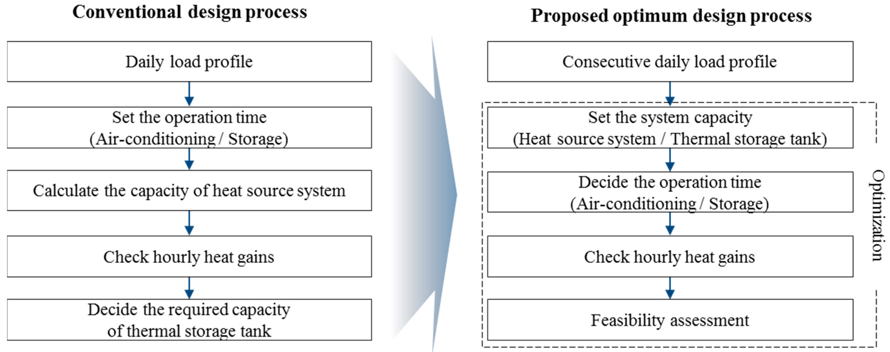
2.1. Review of Conventional Design Process of Thermal Storage System

Before presenting the optimal design process, the conventional design process was examined in advance. According to the Korean standard [15] and ASHRAE standard [16], the design process is as follows. First, the capacity of the heat source system is decided after determining the air-conditioning operation time and heat storage time considering the daily load profile. The amount of hourly heat obtained is calculated and the required capacity of the storage tank is estimated. The start and stop time of the heat source system differ according to the characteristics of the building. This method is useful to apply if the air conditioning time is obvious but it is unsuitable to determine the heat storage time and capacity for a 24-h load. In addition, it is important to verify whether the outcome is reliable to operate.
On the other hand, the thermal storage system in a real working-level is designed roughly by experience and a high safety factor is set to prevent errors on the operation. For example, the capacity of the heat source system is planned at 50% of the peak load and it is multiplied by the storage operation time to set the capacity of the storage tank [17]. According to this method, the system could be oversized so the initial investment cost cannot decrease. In this regard, the maximum saving energy has not been considered through the thermal storage system, which is out of step with the efficient use.

2.2. Outline of Optimal Design Process of Thermal Storage System

Figure 1 presents the proposed design process of the thermal storage system, which reflects several weaknesses found in the conventional one. Unlike the conventional method, the proposed one uses the optimization algorithm with the load profiles of the consecutive days based on the day when the peak load appears. Depending on the system capacity, the operation time is determined. This method is applicable to a variety of load patterns, and can analyze the validity of the design objective.
Figure 2 presents the conceptual diagram of the optimization method proposed in this study. A specific building was modelled by reflecting the weather conditions, occupancy, and architectural elements required for design. In addition, the cooling and heating load were analyzed using a dynamic energy simulation tool, TRNSYS 17 (University of Wisconsin-Madison, Madison, WI, USA), so the hourly load profile and peak load were calculated. Subsequently, a design form was produced by considering the calculated load profile, system efficiency curve, and initial and energy costs and operation method. Regarding the design parameter, the capacity and operation time of each system were taken into account. Following the form, the total investment costs, energy costs, and life cycle cost (LCC) were calculated. In this paper, a genetic algorithm was utilized for an optimization model and the process was performed in the optimization tool (iSIGHT). Finally, the optimal solutions were derived through the process.

2.3. Outline of Genetic Algorithm

The proposed method was based on the genetic algorithm, which is a type of optimization technique to solve a problem by emulating the evolution of organisms. For optimization, the objectives were expressed as equations. In addition, it is suitable for a non-linear optimization problem so it can reflect the design factors, such as the non-linear performance curve of the system [18]. Furthermore, a genetic element called a mutation is placed to prevent converging on the partial optimal solutions so it could be a global search technique. In this regard, using a genetic algorithm is considered as an effective way for obtaining the optimal solution. Figure 3 presents a flow chart to derive the optimal solution by utilizing the genetic algorithm in the proposed method.

3. Examination Method of Proposed Design Process

Table 1 lists the case settings to evaluate the optimal design solutions, which were derived on different objective functions and three load patterns using the proposed design method. To verify the validity and usefulness of the proposed method, it was compared with the conventional designs.

3.1. Outline of a Specific System

Figure 4 shows the configuration of the system, which is a heating system consisting of three electric heat pumps and a thermal storage tank. The heat energy generated from the heat pump works directly from load or works indirectly through the heat storage tank. To obtain the best design on the division of capacity and the number of systems, several properties were reflected, such as the device-specific details and costs depending on the capacity and operation time of each system.

3.2. Design Method of System Capacity

The system capacity is determined based on a 24-h load profile when a peak load occurs. Specifically, the capacity of heat source system is planned on the peak load and the capacity of the thermal storage tank is set by the total daily load [9,15,16]. Figure 5 shows the design load profile as an example.
The peak load ( Q L ( p ) ) is generated at time p and the total daily load ( Q L , d a y ) is the sum of the loads that occur for 24 h a day, which is expressed as Equation (1):
Q L , d a y = t = 0 23 Q L ( t )
In this paper, the capacity of the entire heat pump ( Q H P ) is decided by X% of the peak load ( Q L ( p ) ) and the heat storage tank ( Q H S T ) is calculated according to Y% of the total daily load ( Q L , d a y ) . In terms of X and Y, the integers from 0 to 100 are utilized as the following equations:
Q H P = Q L ( p ) × X ( % )
Q H S T = Q L , d a y × Y ( % )
The total capacity of the heat pump ( Q H P ) is divided into multiple units through integer division. In this study, three heat pumps were used and the integers, a, b, and c, were specified for each heat pump: HP1( Q H P 1 ), HP2( Q H P 2 ), HP3( Q H P 3 ). With regard to the integers, 10 numbers are used; a was varied from 0 to 10, and b and c ranged from 0 to 9. The range of each parameter were set to operate at a minimum of one to a maximum of three heat pumps. In this respect, the number of combinations is 10 3 but a design constraint was set to ensure that the sum of a, b and c was 10. Using the derived a, b and c, the capacities of the three heat pump were calculated as follows:
Q H P 1 = a 10 × Q H P   (   a = { 1 ,   2 ,   3 ,   4 ,   5 ,   6 ,   7 ,   8 ,   9 ,   10 }   )
Q H P 2 = b 10 × Q H P   (   b = { 0 ,   1 ,   2 ,   3 ,   4 ,   5 ,   6 ,   7 ,   8 ,   9 }   )
Q H P 3 = c 10 × Q H P   (   c = { 0 ,   1 ,   2 ,   3 ,   4 ,   5 ,   6 ,   7 ,   8 ,   9 }   )
a + b + c = 10

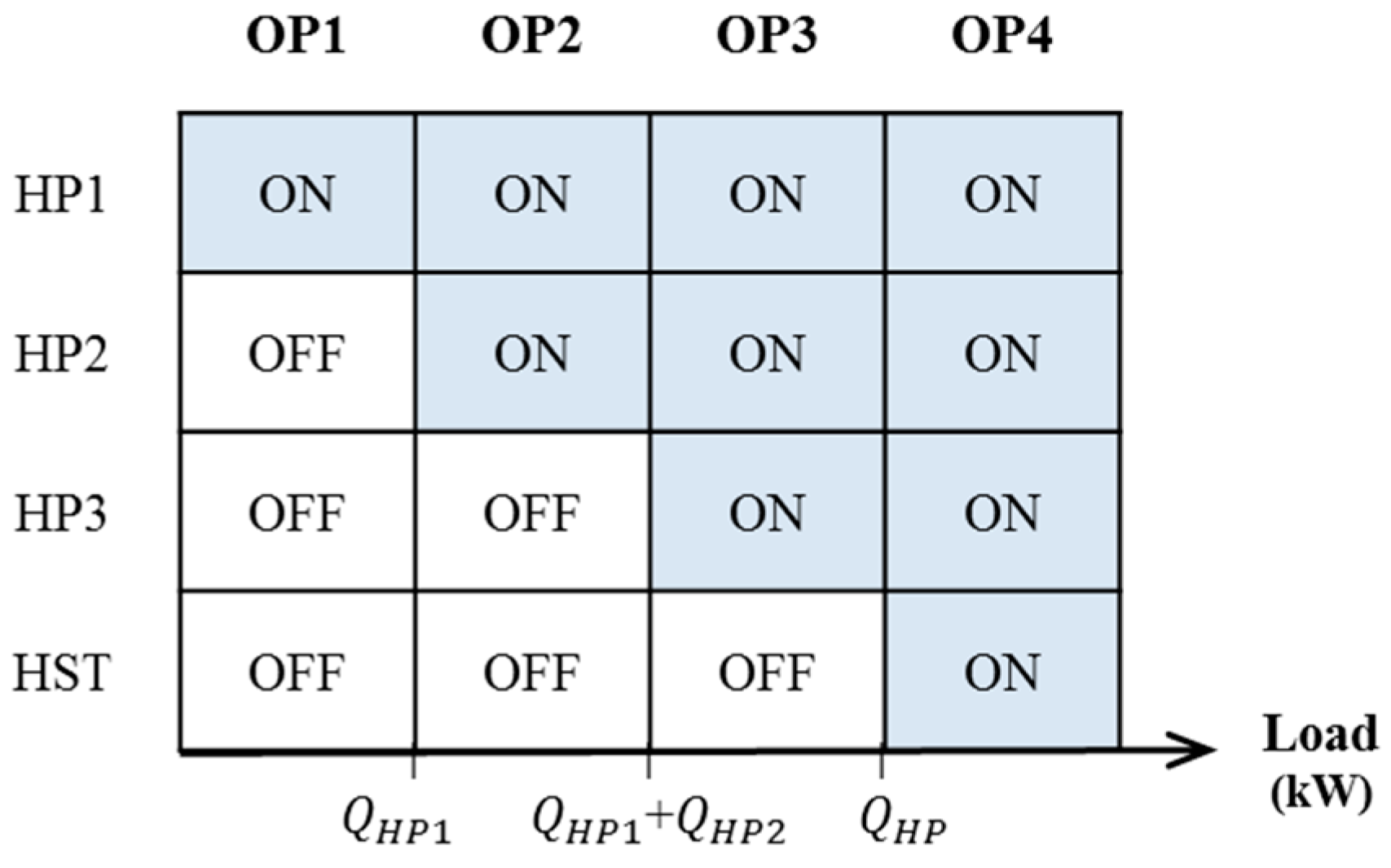
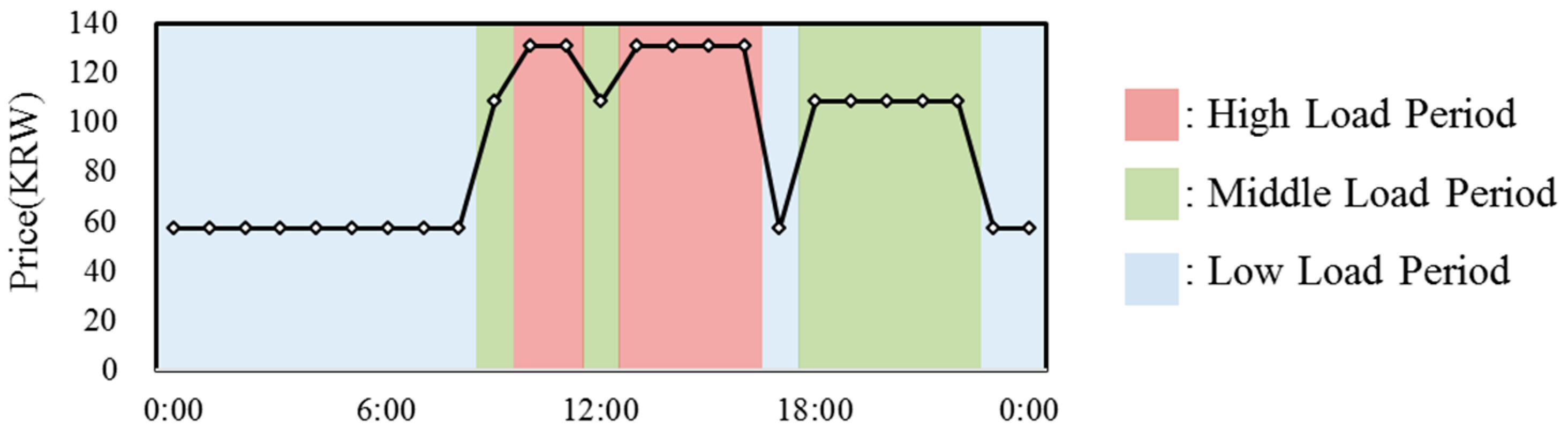
3.3. System Operation Strategy

Figure 6 presents a basic operation strategy that was determined by the amount of building load and storage. The sum of the building load and storage is the required energy production. According to the amount, four operations were assessed.
For each operation, the OP1 is a way that operates only HP1, which is the case if the required energy production is less than the capacity of HP1. In the same way, OP2 is driving HP1 and HP2, and OP3 operates all the heat pumps. OP4 drives the heat rejected from heat storage tank auxiliary if the building load exceeds the total capacity of the heat pumps.
Regarding the storage operation, it works on the storage time if the load pattern is during the day or night. Regarding a 24-h load pattern, it charges if each heat pump has energy remaining corresponding to the building load. In addition, the amount of storage ( Q c h ) is limited not to exceed the capacity of the heat storage tank according to the following equation:
Q c h ( t ) Q l o s s Q H S T
Here, Q l o s s is the heat loss at the heat storage tank. In this paper, the average temperature of the heat storage tank was set to 60 °C and the heat loss occurs depending on the ambient temperature. The heat loss coefficient of the heat storage tank ( K ) was set to 0.7 W/m2K with reference to a previous study [4]:
Q l o s s   = K × A H S T × ( T H S T T a i r )
With regard to the energy production in each heat pump, a partial load ratio was applied to reflect the system efficiency according to the capacity of each heat pump. The system efficiency was reflected to calculate the energy consumption in accordance with the heat pump operation. Section 3.5.4 outlines the method for calculating the energy consumption.

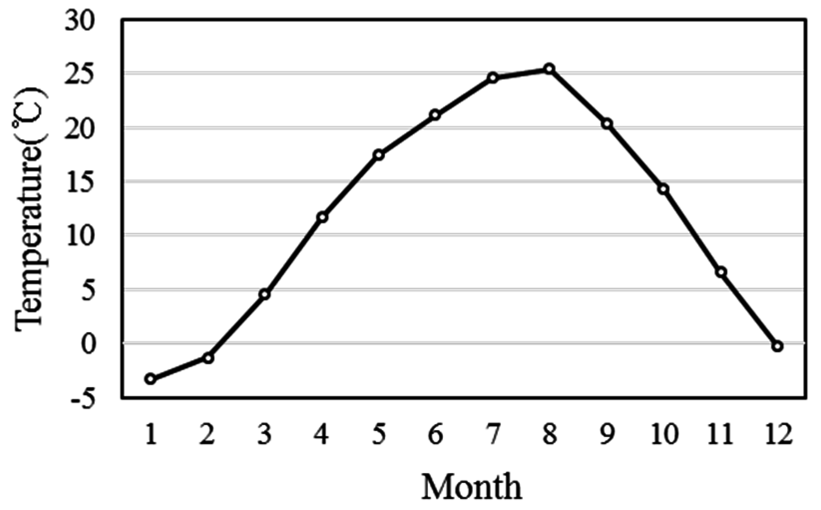
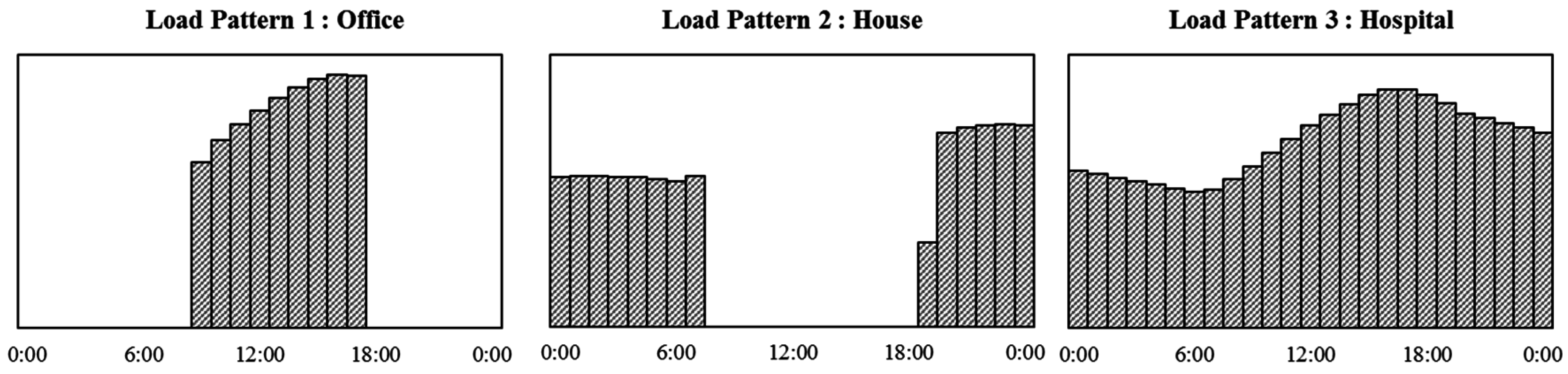
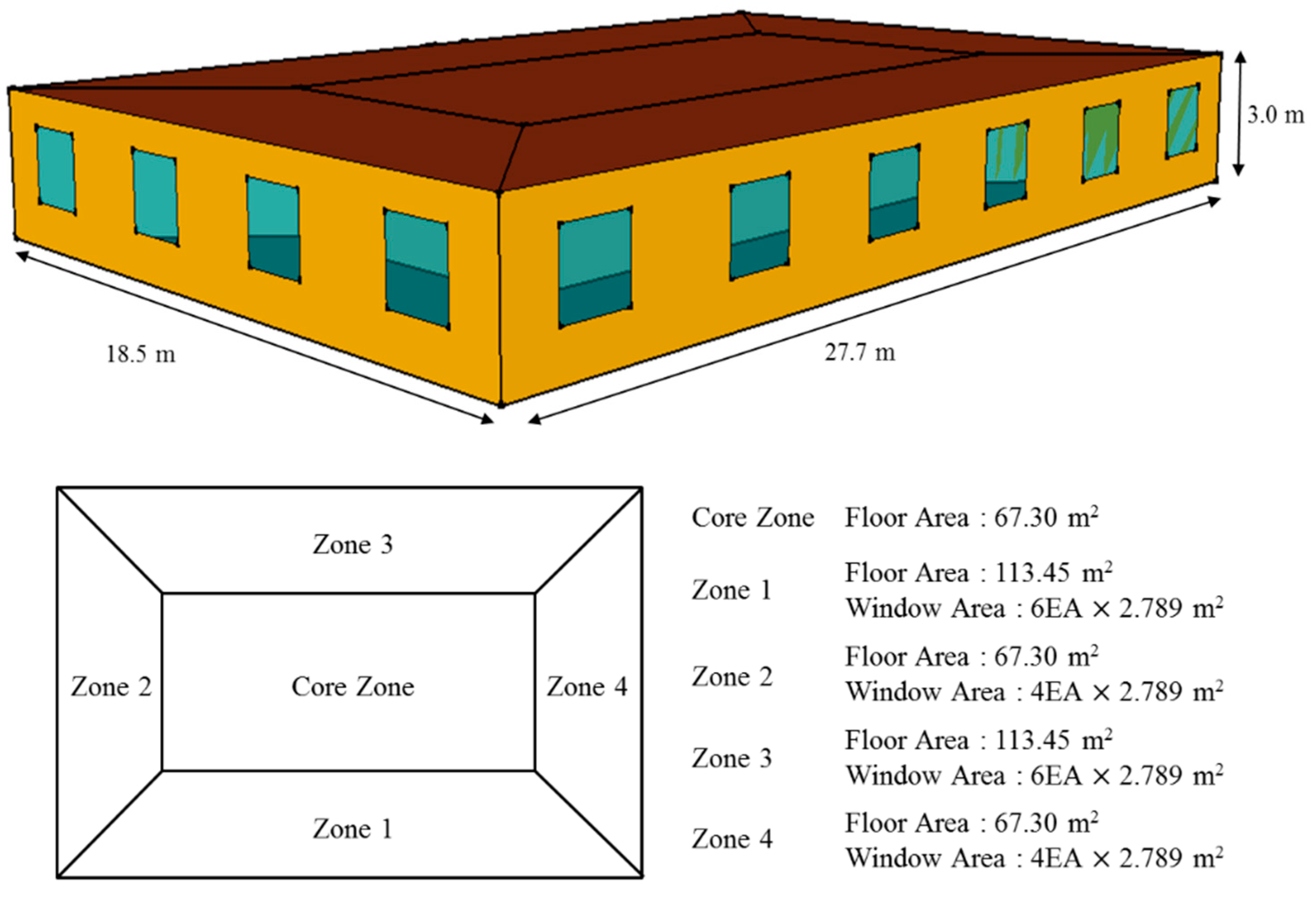
3.4. Conditions of Building Model and Load Patterns

Figure 7 presents a specific building model with a 512.5 m2 floor area. The building model was assumed to be introduced in Seoul (Korea) and the weather condition in Seoul was applied, as shown in Figure 8. Seoul has a temperate climate at latitude 37° N. In this paper, the heating and cooling loads were analyzed using a dynamic energy simulation tool, TRNSYS 17. In TRNSYS, a multi-zone building component was utilized, which is connected to the building environment tool, TRNBuild (University of Winscosin-Madison, Madison, WI, USA). Using TRNBuild, various elements for the building were adjusted, including the characteristics of the wall and layer, which are indicated in Table 2 referring to a previous research report [19]. In addition, Table 3 lists the indoor setting conditions with reference to the SAREK Handbook [20]. To study the three different load patterns, each load pattern was assumed to have a specific air-conditioning time and reflect the indoor conditions of the representative building type according to the standard calculation conditions [20]. Load pattern 1 occurs during the day normally at the office. Load pattern 2 appears in nighttime representatively at a house. Load pattern 3 has a 24-h load such as a hospital. In addition, this paper describes only the heating operation conditions. Through load analysis, three load patterns were obtained, as indicated in Figure 9, which is to derive the design solutions in each building type using the design method.

3.5. Calculation Conditions for Optimization

3.5.1. Optimization Variables and Parameter

The optimization variables were set, as shown in Table 4, to calculate the system capacity, and the detailed information about each variable was mentioned above.
Table 5 lists the main control parameters used in the genetic algorithm (GA). The parameters of GA influence the number of cases, calculation time, and diversity of the solutions. Therefore, it is important to input an appropriate figure for each parameter. Among the parameters of GA, the size of the sub-population and the number of islands involved in the initial population are set by multiplying them, and the number of generations indicates the following generations that can be created by the initial population. That is, the number of islands, the size of sub-population and the number of generations are the key elements to determine the total calculation cases. Moreover, it is important to consider not only the range of initial populations, but also set how many generations to create. As the calculation cases increase, the more accuracy to find the optimal solution rises but a longer time is needed for optimization. On the other hand, if the number of calculation cases is lower, it derives the result faster but it cannot converge the optimal solution. In addition, the rate of crossover, the rate of mutation and the rate of migration improves the diversity of the solutions. In this paper, new individuals are generated continuously by setting 100% as the rate of crossover. Migration moves individuals to each island and mutation creates slightly different versions of the individuals. Therefore, 5%–10% is known to be an appropriate value because a high ratio makes it difficult to converge. In this paper, 30,000 cases were utilized for the total calculation, and the entire area was searched by the mutation ratio and calculation cases. The value of each parameter was derived through a case study and it was referred to previous studies [21,22].

3.5.2. Objectives

The objective functions were set up in two to compare the optimal designs in accordance with the objectives; one (obj1) is to minimize LCC and another (obj2) is to minimize the energy cost. These are expressed as follows:
obj1 = min(LCC)
obj2 = min(CE)

3.5.3. Initial Costs

The systems in consideration for the initial investment costs are the heat pump and heat storage tank. When installing each system, the costs of piping, pumps and labor costs are also generated. In this study, it was assumed that it occupies small part when comparing the economy so that it was excluded from the initial cost calculations.
In this study, it was assumed that the system’s investments have a linear relationship with the system’s size because numerous capacities of the system can be derived, making it difficult to collect all the investment costs for each system size from the catalog. Moreover, a report from the Korean energy agency suggests that the investment cost depends on the system’s capacity [23]. Therefore, this study simplified it and the initial investment costs were estimated with reference to the price at the company certificated from the public procurement service [24], as shown in Table 6. According to the capacity of each system type, it has been calculated and the total initial investment cost ( C I ) is determined by adding each cost:
C I = C H P + C H S T

3.5.4. Energy Costs

In this paper, it was assumed that the average coefficient of performance (COP) was 2.5 according to the average outdoor temperature in winter [25]. In addition, the energy consumption rate ( η H P ) was utilized in the calculation with the second degree polynomial function based on the previous studies [18,26]. Here, the minimum value of the part load ratio (PLR) was set to 0.2 in this paper:
P L R =   Q L o a d Q H P
η H P = a 0 + a 1 × P L R + a 2 × P L R 2
With the calculated primary energy consumptions, the energy costs were derived by applying a unit price of each heat source. In this paper, electric energy is consumed and the hourly electric energy charges are estimated based on the electricity tariff from the Korean Electric Power Corporation [5], which is shown in Figure 10. Figure 10 shows the light load period, middle load period, and heavy load period divided by the time interval and the charges in each section applied to the differential:
C E , d a y ( d ) = t = 0 23 ( Q H P 1 ( t ) η H P 1 ( t ) + Q H P 2 ( t ) η H P 2 ( t ) + Q H P 3 ( t ) η H P 3 ( t ) ) · P ( t )
C E = d = 1 7 C E , d a y ( d ) × 16
Therefore, total energy cost per day ( C E , d a y ) is the sum of the hourly energy costs, which is expressed in the equation above. The annual energy cost ( C E ) was calculated during the heating period, which was assumed for 4 months and based on the design days for 7 days. To achieve reliable results over the entire heating season, the modification factor was considered. Because this paper set the design days for 7 days, it was assumed that the load pattern is the same as the design days during a month period. If so, the energy costs for one month can be estimated. The monthly heating energy costs were then calculated using the modification factor, which is based on the monthly heating load analysis.

3.5.5. Maintenance Costs

Table 7 lists the maintenance costs applied to calculate the repair and replacement costs for each cycle of the heat pump in accordance with previous research [27].

3.5.6. Life Cycle Cost (LCC)

In this paper, it was assumed that the LCC is derived from the net present value (NPV) method over a 20-year-period of useful life of system [28]. As elements of the LCC, this study considered the initial costs, energy costs, and maintenance costs. In accordance with the net present value, the LCC is calculated by adding the elements that are divided to converting recurring costs (A) and non-recurring costs (F) according to the following equation. Here, the real discount rate (i) is applied to 3.4% referring to previous studies [9]:
L C C =   F i ( 1 + n ) n + A [ ( i + i ) 1 ] i ( 1 + i ) n

3.5.7. Constraints

The main constraints of the optimization process are as follows, including some mentioned above:
  • If the capacity of the heat storage tank is over 0 kW, the capacity of the heat pump should not be 100% of the peak load. On the other hand, if the capacity of the heat storage tank is 0 kW, the capacity of the heat pump should not be less than 100% of the peak load;
  • As for design variables, the sum of a, b, and c should be 10.
If it breaks the constraints, a penalty is applied as a value to the objective functions.

4. Optimization Results and Discussion

4.1. Optimum Design Solutions Analysis

In this paper, 30,000 individuals in each case were examined to obtain the best designs, which are summarized in Table 8. According to the results, the optimal designs were drawn differently depending on the load pattern and objective function. Figure 11 presents the optimal design solutions.
First of all, the results of Cases 1 and 2 showed the largest difference according to the objectives, even in the same daytime load. In Case 1 of minimizing LCC, the optimal solution was derived to design the heat pump as 79% of the peak load and the heat storage tank with 12% of the daily total load. On the other hand, in Case 2 of minimizing the energy cost, the optimal solution was to design 40% of the peak load as the capacity of the heat pump and heat storage tank with 54% of the daily total load. Compared to Case 1, it was determined that Case 2 had a larger capacity of the heat storage tank, to store heat energy sufficiently using the relatively low cost of late-night electricity. In terms of the costs, the energy cost in Case 2 was approximately 156,000 KRW/year smaller but the initial cost in Case 2 was double so Case 1 cut 4,400,000 KRW at the LCC compared to Case 2.
In Cases 3 and 4, the results were the same. The heat pump was planned to 98% of the peak load and the heat storage tank was designed as 1% of the daily total load. As a result, the heat pump was designed to operate directly to the building load rather than act as a storage operation using the low cost of midnight electricity effectively.
In Cases 5 and 6, the optimal design solutions were derived similarly. In this load pattern for 24 h, there is a slight difference between the peak load and the average load so it is more efficient to operate the heat pump directly. Accordingly, it was determined that the capacity of the heat pump is similar to the peak load. Regarding the costs, in Case 6, the energy cost was approximately 9000 KRW/year smaller.
Overall, the optimal design solutions were derived differently depending on the purpose and the objective function of the building and its characteristics stood out in the daytime load. Moreover, the ratio of each cost was different with the load patterns. In this regard, the design solution that meets the design objectives of the building can be deduced.

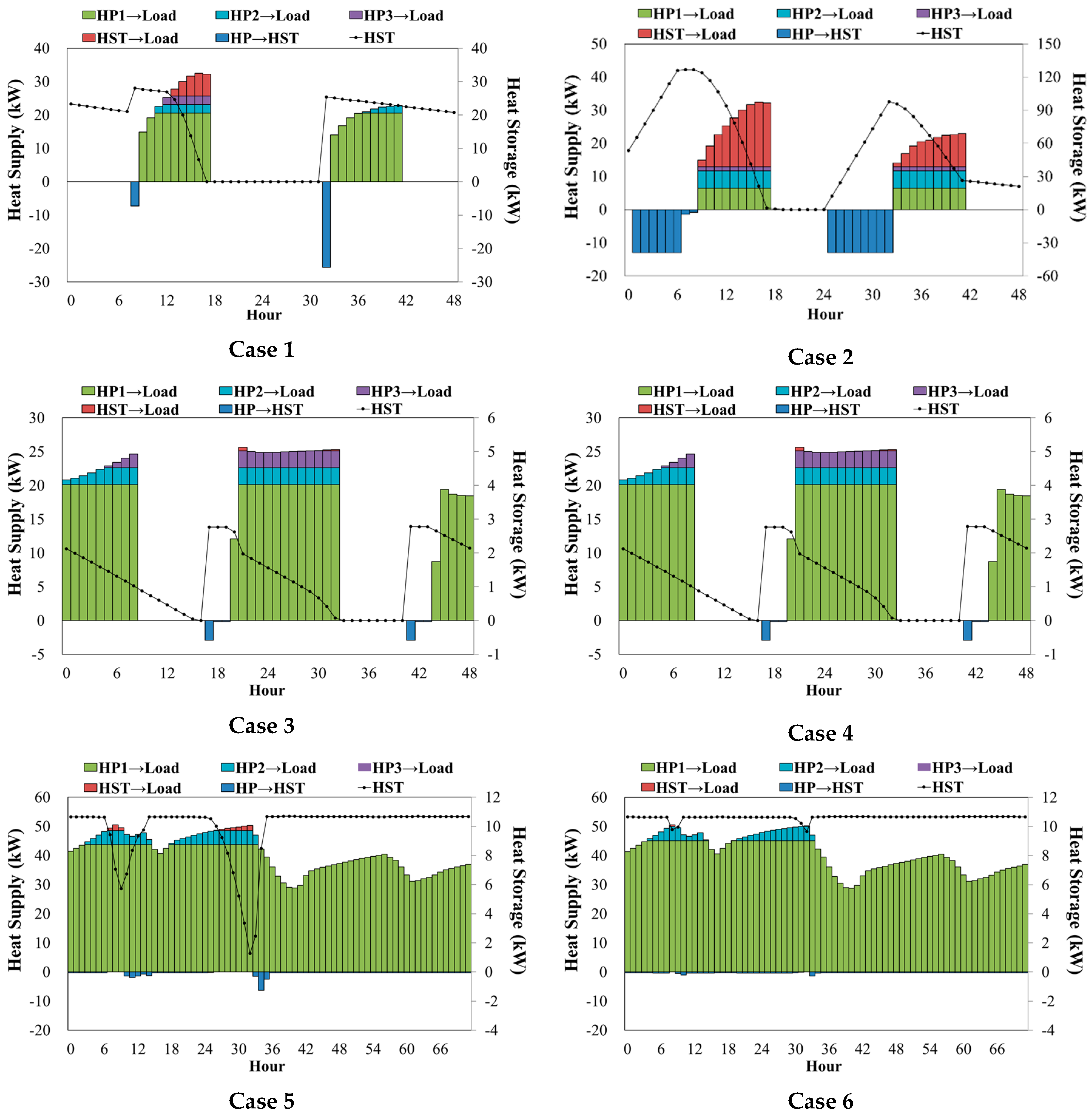
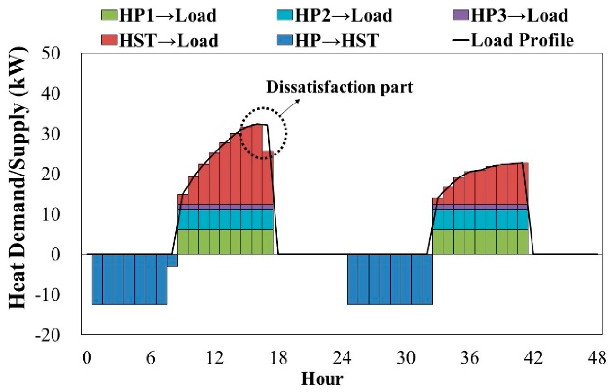
4.2. Review of Operation Planning

The proposed design method is a way to consider the operation together based on the designed load profile. In this section, the operation aspects of the optimal designs were determined.
Figure 12 presents the operation planning according to the load pattern and objective function. In this paper, a representative 2 days of the design days is shown. The graph shows the hourly energy rate. The histogram of the upper along the X-axis represents the amount of energy corresponding to the building load with the heat pump and the heat storage tank. The lower part along the X-axis means the heat storage energy rates. The line graph represents the energy remaining in the storage tank.
First, as shown in Figure 12, Case 1 operates the heat pump directly to the building load. On the other hand, Case 2 stores the heat energy during the night by utilizing the available storage time and discharges a significant amount of heat during the day, which is to minimize the energy cost by utilizing mostly low-cost electricity. Cases 3 and 4 mainly operate the heat pump directly on the building load during the air-conditioning time when the energy cost is relatively low. Cases 5 and 6 indicate that the period to store heat energy is insufficient so the heat pump mainly operates directly.
The proposed method makes it possible to examine the remaining energy of the heat storage tank and check the operation aspects as to whether the system works efficiently. According to the outcome, each system works properly to meet the building load, and the required heat energy is stored so the system is determined to be designed effectively without being excessive.

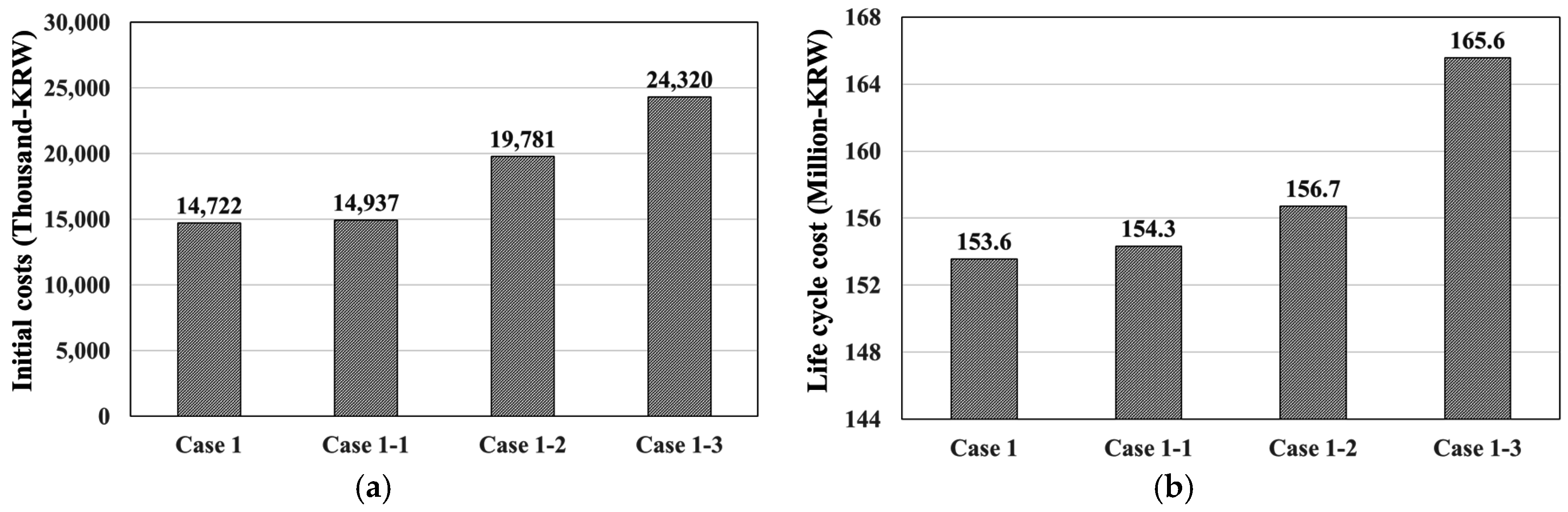
4.3. Feasibility Study

In this section, a feasibility study was conducted to verify the validity compared to the conventional designs. In this study, Case 1 was selected as a representative design, which is to minimize the LCC in the daytime load. To compare with the conventional designs, the following three cases were set. In Case 1-1, the heat pump is operated without a heat storage tank. Case 1-2 was followed by the conventional thermal system design process and the capacity of the heat pump and required heat storage tank were calculated when the air-conditioning and heat storage operation time were 9 h and 10 h, respectively. Case 1-3 was applied to real-working practice; the heat pump capacity was set to 50% of the peak load and the heat storage tank was designed to store the amount of energy by driving the heat pump for 10-h storage operation. Figure 13 and Table 9 lists the estimated initial investment costs, annual energy costs and LCC for each design.
As shown in Table 8, all the designs show a difference in each part of the cost. First, comparing with the case to operate the only heat pump without a heat storage tank, the optimal solution could reduce 215,000 KRW of the initial investment cost and 768,000 KRW in the LCC. Through this, it was determined that it can be more efficient to combine a heat storage tank. In addition, the annual energy costs when the case with the conventional design process was 90,000 KRW cheaper than the optimum but the initial costs required an additional 2,000,000 KRW so it is inefficient in terms of the LCC. In the case of real-working practical design, it was the most excessive design having more than 10 million KRW as the initial investment cost and the energy cost and LCC were higher than other cases as well.
In addition, the conventional designs should consider the safety factor including heat losses from the heat storage tank. If not, it would not be satisfied with the load, as shown in Figure 14. In this regard, the proposed method is a useful way in that the optimal design solution is derived after checking the operation planning of the designs.
Therefore, the design solutions proposed in this study are eligible for the optimal heat storage system compared to any other conventional designs. Furthermore, real-working practice is required to improve the designs to prevent oversizing, resulting in higher investment cost.

4.4. Optimal Solutions with a Multi Objective Approach

In previous sections, the designs differed according to the objective functions. In particular, in the daytime load pattern, the difference between the designs was significant so that it is essential to approach the optimal design solutions using a multi-objective genetic algorithm. Therefore, in this section, an analysis with a multi-objective genetic approach was conducted. To solve the multi-objective problem, the Pareto analysis method was accompanied to derive multiple optimal solutions. Figure 15 presents the Pareto front result of the daytime load pattern.
The optimal design solutions are distributed from one objective function to another objective function. This analysis approach helps consumers make an efficient choice considering their economic conditions.

5. Conclusions

In this study, we proposed a design method of heat source system including heat storage tank utilizing a genetic algorithm and derived optimum design solutions according to three load patterns and different objective functions. The main results of this paper are as follows:
This paper proposed a design method of a heat source system including heat storage tank utilizing a genetic algorithm and derived optimal design solutions according to three load patterns and different objective functions. The main results of this paper were as follows:
  • According to the load patterns and objective functions, a range of solutions were derived to meet the design purposes and the costs were different irregularly. When the load occurs during the day, the solutions showed the largest differences with the objective functions.
  • By checking the operation planning, the proposed method could consider the efficient operation, oversized-design, heat losses, safety factor, and energy remaining in the heat storage tank.
  • The proposed method could make the most efficient design in terms of the initial investment cost and LCC compared to the conventional heat storage designs, as well as the system using only the heat source system. Moreover, it was confirmed that it is necessary to improve the method in the real working-process, which led to energy and economic consumption by oversizing the system.
  • Since an oversized design operates inefficiently, it was confirmed that a thermal storage system is required for optimal design.
In the future, the optimal design guidelines will be developed regarding the scale, purpose, and region of building for economic and energy efficiency. In addition, this study will continue to utilize the proposed method in a more efficient manner, especially when using a renewable energy system, which has more benefits for introducing a heat storage system to solve the high initial investment cost and the intermittent energy production.

Acknowledgments

This work was supported by the New & Renewable Energy Core Technology Program of the Korea Institute of Energy Evaluation and Planning (KETEP), granted financial resource from the Ministry of Trade, Industry & Energy, Korea. (No. 20133030110900). This research was supported by Basic Science Research Program through the National Research Foundation of Korea (NRF) funded by the Ministry of Education, Science and Technology (No. 2015R 1D 1A3A01020132).

Author Contributions

The authors Min Gyung Yu and Yujin Nam developed the methodology and wrote the full manuscript.

Conflicts of Interest

The authors declare no conflict of interest.

References

  1. Key World Energy Statistics 2015; International Energy Agency (IEA): Paris, France, 2015; Available online: http://www.iea.org/publications/freepublications/publication/KeyWorld_Statistics_2015.pdf (accessed on 5 September 2016).
  2. Annual Energy Outlook 2016; U.S. Energy Information Administration (EIA): Washington, DC, USA, 2016. Available online: http://www.eia.gov/forecasts/aeo/index.cfm (accessed on 5 September 2016).
  3. Kang, W.K. A tendency of thermal storage for air-conditioning system. J. Electr. World Mon. Mag. 1990, 157, 19–25. [Google Scholar]
  4. Yu, M.G.; Nam, Y.; Yu, Y.; Seo, J. Study on the system design of a solar assisted ground heat pump system using dynamic simulation. Energies 2016, 9, 291. [Google Scholar] [CrossRef]
  5. Korean Electric Power Corporation (KEPCO). Available online: http://cyber.kepco.co.kr (accessed on 14 July 2016).
  6. Sanaye, S.; Hekmatian, M. Ice thermal energy storage (ITES) for air-conditioning application in full and partial load operating modes. Int. J. Refrig. 2016, 66, 181–197. [Google Scholar] [CrossRef]
  7. Osterman, E.; Butala, V.; Stritih, U. PCM thermal storage system for ‘free’ heating and cooling of buildings. Energy Build. 2015, 106, 125–133. [Google Scholar] [CrossRef]
  8. Romani, J.; Gracia, A.; Cabeza, L.F. Simulation and control of thermally activated building systems (TABS). Energy Build. 2016, 127, 22–42. [Google Scholar] [CrossRef]
  9. Yu, M.G.; Nam, Y.; Lee, K.H. Design method of heat storage type ground source heat pump system considering energy load pattern of greenhouse. KIEAE J. 2015, 15, 57–63. [Google Scholar] [CrossRef]
  10. Sun, Y.; Wang, S.; Xiao, F.; Gao, D. Peak load shifting control using different cold thermal energy storage facilities in commercial buildings: A review. Energy Convers. Manag. 2013, 71, 101–112. [Google Scholar] [CrossRef]
  11. Ikeda, S.; Ooka, R. Optimal operation of energy systems including energy storage equipment under different connections and electricity prices. Sustain. Cities Soc. 2016, 21, 1–11. [Google Scholar] [CrossRef]
  12. Renaldi, R.; Kiprakis, A.; Friedrich, D. An optimization framework for thermal energy storage integration in a residential heat pump heating system. Appl. Energy 2016. [Google Scholar] [CrossRef]
  13. Shirazi, A.; Najafi, B.; Aminyavari, M.; Rinaldi, F.; Taylor, R.A. Thermal-economic-environmental analysis and multi-objective optimization of an ice thermal energy storage system for gas turbine cycle inlet air cooling. Energy 2014, 69, 212–226. [Google Scholar] [CrossRef]
  14. Wu, Q.; Ren, H.; Gao, W.; Ren, J. Multi-objective optimization of a distributed energy network integrated with heating interchange. Energy 2016, 109, 353–364. [Google Scholar] [CrossRef]
  15. Park, J.I. Building utility system design criteria. J. SAREK 2004, 33, 31–41. [Google Scholar]
  16. ASHRAE. ASHRAE Handbook HVAC System and Equipment; ASHRAE: Atlanta, GA, USA, 2012. [Google Scholar]
  17. Kang, H.K. Thermal storage cooling-heating system by GSHP. In Proceedings of the 2005 HARFKO, Heating, Air-Conditioning, Refrigeration and Fluid Exhibition Korea, Goyang, Korea, 25–27 May 2005.
  18. Yu, M.G.; Nam, Y. A study on the multi-level optimization method for heat source system design. J. SAREK 2016, 7, 299–304. [Google Scholar] [CrossRef]
  19. Torcellini, P.; Deru, M.; Griffith, B.; Benne, K. DOE commercial building benchmark models. In Proceedings of the 2008 ACEEE Summer Study on Energy Efficiency in Buildings, Pacific Grove, CA, USA, 17–22 August 2008.
  20. SAREK. SAREK Handbook HVAC System and Equipment; SAREK: Seoul, Korea, 2011. [Google Scholar]
  21. Ooka, R.; Komamura, K. Optimal design method for building energy systems using genetic algorithms. Build. Environ. 2009, 44, 1538–1544. [Google Scholar] [CrossRef]
  22. Ooka, R.; Kayo, G. Building energy system optimizations with utilization of waste heat from cogenerations by means of genetic algorithm. Energy Build. 2010, 42, 985–991. [Google Scholar]
  23. Korean Energy Agency. Available online: http://www.kemco.or.kr/ (accessed on 5 September 2016).
  24. Offer & Merchandise Mall (OMMall). Available online: http://ommall.net/ (accessed on 2 February 2016).
  25. Jun, C.H.; Lee, H.S.; Kim, J.D.; Yoon, J.I. Performance characteristics of air-cooled heat pump system using hydrocarbon refrigerants according to variation of outdoor temperature. Korean J. Air-Cond. Refrig. Eng. 2006, 3, 218–224. [Google Scholar]
  26. Seo, J.; Ooka, R.; Kim, J.T.; Nam, Y. Optimization of the HVAC system design to minimize primary energy demand. Energy Build. 2014, 79, 102–108. [Google Scholar] [CrossRef]
  27. Lee, I.G.; Kang, H.W.; Won, Y.M.; Kim, Y.S. Economic Evaluation for Heating and Cooling System by Using Gas Energy and Geothermal Energy Based on LCC Analysis. J. Archit. Inst. Korea 2011, 10, 161–168. [Google Scholar]
  28. Hafez, O.; Bhattacharya, K. Optimal planning and design of a renewable energy based supply system for microgrids. Renew. Energy 2012, 45, 7–15. [Google Scholar] [CrossRef]
Figure 1. Changes in the design process of thermal storage system.
Energies 09 00849 g001
Figure 2. Optimization process of thermal storage system.
Energies 09 00849 g002
Figure 3. Genetic algorithm flowchart.
Energies 09 00849 g003
Figure 4. Conceptual diagram of system configuration. HP: Heat pump; HST: Heat storage tank.
Energies 09 00849 g004
Figure 5. 24-h load profile for example.
Energies 09 00849 g005
Figure 6. System operation strategy.
Energies 09 00849 g006
Figure 7. Building model.
Energies 09 00849 g007
Figure 8. Seoul weather condition.
Energies 09 00849 g008
Figure 9. Three load patterns for example.
Energies 09 00849 g009
Figure 10. Electricity price.
Energies 09 00849 g010
Figure 11. Optimum design solutions.
Energies 09 00849 g011aEnergies 09 00849 g011b
Figure 12. Operation planning of optimum solution.
Energies 09 00849 g012
Figure 13. Comparison of the initial cost and Life cycle cost (LCC) in cases. (a) Initial costs in cases; (b) Life cycle cost in cases.
Energies 09 00849 g013
Figure 14. Operation check.
Energies 09 00849 g014
Figure 15. Pareto-optimal solutions in daytime load pattern.
Energies 09 00849 g015
Table 1. Case setting.
CasesLoad PatternObjective
Case 1Load pattern 1:
Daytime
Life Cycle Cost
Case 2Energy cost
Case 3Load pattern 2:
Nighttime
Life Cycle Cost
Case 4Energy cost
Case 5Load pattern 3:
24 h
Life Cycle Cost
Case 6Energy cost
Table 2. Properties of building parts and input data.
Building PartsHeat Transfer Coefficient (U-Value) (W/m2K)
External wall0.510
Internal wall4.351
Ceiling4.158
Floor0.039
Roof0.316
Window2.89
Table 3. Indoor conditions of three building types.
Building TypeSet TemperatureOperation TimeVentilationPersonInternal Heat Gain
Office20 °C09–18 h1/h0.2 person/m240 W/m2
House22 °C19–08 h1/h4 person/150 m230 W/m2
Hospital23 °C24 h2/h0.2 person/m215 W/m2
Table 4. Optimization variables.
VariablesMinMaxStep
X01001
Y01001
A1101
B091
C091
Heat storage0101
Table 5. Genetic algorithm (GA) parameter.
GA ParameterValue
Size of sub-population30
Number of island20
Number of generation50
Rate of crossover1
Rate of mutation0.07
Rate of migration0.05
Table 6. Initial costs.
SystemCostUnits
Heat Pump (HP)460,000KRW/kW
Heat storage tank (HST)960,000KRW/m3
Table 7. Maintenance costs.
SystemRepairReplacement
PeriodRatePeriodRate
Heat pump7 years7%20 years100%
Table 8. The results of optimization cases.
CasesHP1HP2HP3HSTInitial CostsEnergy CostsLCC
KRWKRWKRW
Case 120.5 kW2.6 kW2.6 kW28.3 kW14,722,0009,598,000153,554,000
Case 26.5 kW5.2 kW1.3 kW127.4 kW19,122,0009,432,000154,994,000
Case 320.1 kW2.5 kW2.5 kW2.9 kW11,860,0007,562,000127,391,000
Case 420.1 kW2.5 kW2.5 kW2.9 kW11,860,0007,562,000127,391,000
Case 543.7 kW4.9 kW0 kW11 kW23,456,00017,078,000282,049,000
Case 645 kW5 kW0 kW11 kW24,154,00017,069,000283,041,000
Table 9. The feasibility assessment compared with conventional cases.
CasesSystemInitial CostsEnergy CostsLCC
HPHSTKRWKRWKRW
Optimum25.7 kW28.3 kW14,722,0009,598,000153,554,000
Case 1-132.5 kW0.0 kW14,937,0009,615,000154,322,000
Case 1-212.4 kW136.4 kW19,781,0009,508,000156,703,000
Case 1-316.3 kW163.0 kW24,320,0009,656,000165,556,000

