Article

Energy Consumption and Saving Analysis for Laser Engineered Net Shaping of Metal Powders

1
School of Mechanical Engineering, Dalian University of Technology, Dalian 116023, China
2
Department of Industrial, Manufacturing and System Engineering, Texas Tech University, Lubbock, TX 79409, USA
*
Author to whom correspondence should be addressed.
Energies 2016, 9(10), 763; https://doi.org/10.3390/en9100763
Submission received: 29 June 2016 / Revised: 15 September 2016 / Accepted: 18 September 2016 / Published: 22 September 2016
(This article belongs to the Special Issue Energy Saving Design for Manufacturing Process, Product, and System)

Abstract

:
With the increasing awareness of environmental protection and sustainable manufacturing, the environmental impact of laser additive manufacturing (LAM) technology has been attracting more and more attention. Aiming to quantitatively analyze the energy consumption and extract possible ways to save energy during the LAM process, this investigation studies the effects of input variables including laser power, scanning speed, and powder feed rate on the overall energy consumption during the laser deposition processes. Considering microhardness as a standard quality, the energy consumption of unit deposition volume (ECUDV, in J/mm3) is proposed as a measure for the average applied energy of the fabricated metal part. The potential energy-saving benefits of the ultrasonic vibration–assisted laser engineering net shaping (LENS) process are also examined in this paper. The experimental results suggest that the theoretical and actual values of the energy consumption present different trends along with the same input variables. It is possible to reduce the energy consumption and, at the same time, maintain a good part quality and the optimal combination of the parameters referring to Inconel 718 as a material is laser power of 300 W, scanning speed of 8.47 mm/s and powder feed rate of 4 rpm. When the geometry shaping and microhardness are selected as evaluating criterions, American Iron and Steel Institute (AISI) 4140 powder will cause the largest energy consumption per unit volume. The ultrasonic vibration–assisted LENS process cannot only improve the clad quality, but can also decrease the energy consumption to a considerable extent.

1. Introduction

As a widely used additive manufacturing technology, laser engineering net shaping (LENS) is now serving as one of the key technologies in the direct manufacturing or repairing of metal parts. Starting from a computer-aided design (CAD) solid file, the LENS process produces parts layer by layer with the heat input of a high-powered laser. Compared to traditional surface treatment processes, LENS has a higher repair efficiency, less post-processing, a higher cooling rate, and a smaller heat-affected zone, thus achieving better mechanical behaviors after deposition processes [1]. Being different from other additive manufacturing processes, LENS can fabricate near-net-shaped prototypes, high quality metal parts, and even special tooling for injection molds [2]. Recently, LENS has been successfully applied in the direct fabrication of complex structural components [3], functionally graded coatings [4], high-value-added components repair [5], and special industries such as aerospace, defense, biomedical, etc. [6].
Since it was developed by Sandia National Laboratories in 1997, LENS has exhibited a great potential to revolutionize metal parts fabrication and it has attracted more and more attention in both academia and other industries. In the last decades, the research focus has been the optimization of mechanical properties and microstructures of components fabricated by LENS [7,8,9,10,11,12,13,14], and thermal modeling and control over the entire powder deposition process [15,16,17,18,19]. These investigations have provided a clear understanding of the characteristics of LENS and have promoted this technology as a major step towards actual industrial applications. On the other hand, with the increasing awareness of energy saving and environmental protection, environmental issues have aroused more concerns during the product manufacturing processes. Both governments and corporations are being pushed to pay more attention to the environmental burdens of the product. As a new technology, LENS requires energy consumption analysis before its extensive industrial applications.
Energy consumption analysis is the very first step and is essential for the development of energy-saving technologies and scientific environmental assessment for LENS. During the powder deposition process, several modules including high-powered laser generation, powder feeding and delivery, and motion control will cause significant electricity energy consumption. The input variables will also affect the total power consumption and distribution to a large extent. Several studies have been conducted to evaluate the power consumption of the LENS system. The focus was the identification of laser energy transfer efficiency or power distribution routes during the deposition process. However, the energy input and distribution were obtained through the indirect measurement and modeling method [20,21,22]. Very few reports have quantitatively analyzed the energy consumption of LENS, much less the effects of input variables on the overall energy consumption during the laser deposition process.
Apart from analyzing the energy consumption, researchers have started exploring the potential energy-saving strategies in the LENS process. Currently, the main idea of the energy-saving methodology is to utilize the reaction-generated heat or preheat the substrate, thereby reducing the energy requirement for laser power [23]. Although this method can reduce the energy input, it will not affect the molten pool reaction and cannot improve the part quality. Methodologies that realize energy savings while producing materials with superior properties are critically needed [24].
Ultrasonic vibration has been used in assisting the LENS process for metallic parts fabrication processes to improve the parts’ quality, and it has been proven that ultrasonic vibration is beneficial in reducing the porosity, micro-cracks, and grain size of the fabricated parts, which can help improve the mechanical property [25]. However, no report about the effects of ultrasonic vibration on the overall energy consumption during the LENS process has been documented, which has limited its application in industries.
In this paper, an energy consumption measurement system is set up and a series of experiments are conducted to analyze the energy consumption and saving opportunities in the LENS process. The effects of input variables and kinds of powders on the overall energy consumption during laser deposition processes are extensively investigated. Also, the paper examines the potential energy-saving benefits in the ultrasonic vibration–assisted LENS process.

2. Materials and Methods

2.1. Material Properties

It has been reported that nickel-based, cobalt-based, and iron-based materials are commonly used powders during LENS processes [26]. Considering the range of materials availability in LENS and the principle of joining dissimilar materials using a laser beam [27], Inconel 718 (nickel-based), Stellite 1 (cobalt-based), Tribaloy T-800 (cobalt-based) and American Iron and Steel Institute (AISI) 4140 (iron-based) are selected as the candidate fabricating materials. The AISI 4140 square plates are utilized as the substrate. The material properties are shown in Table 1.

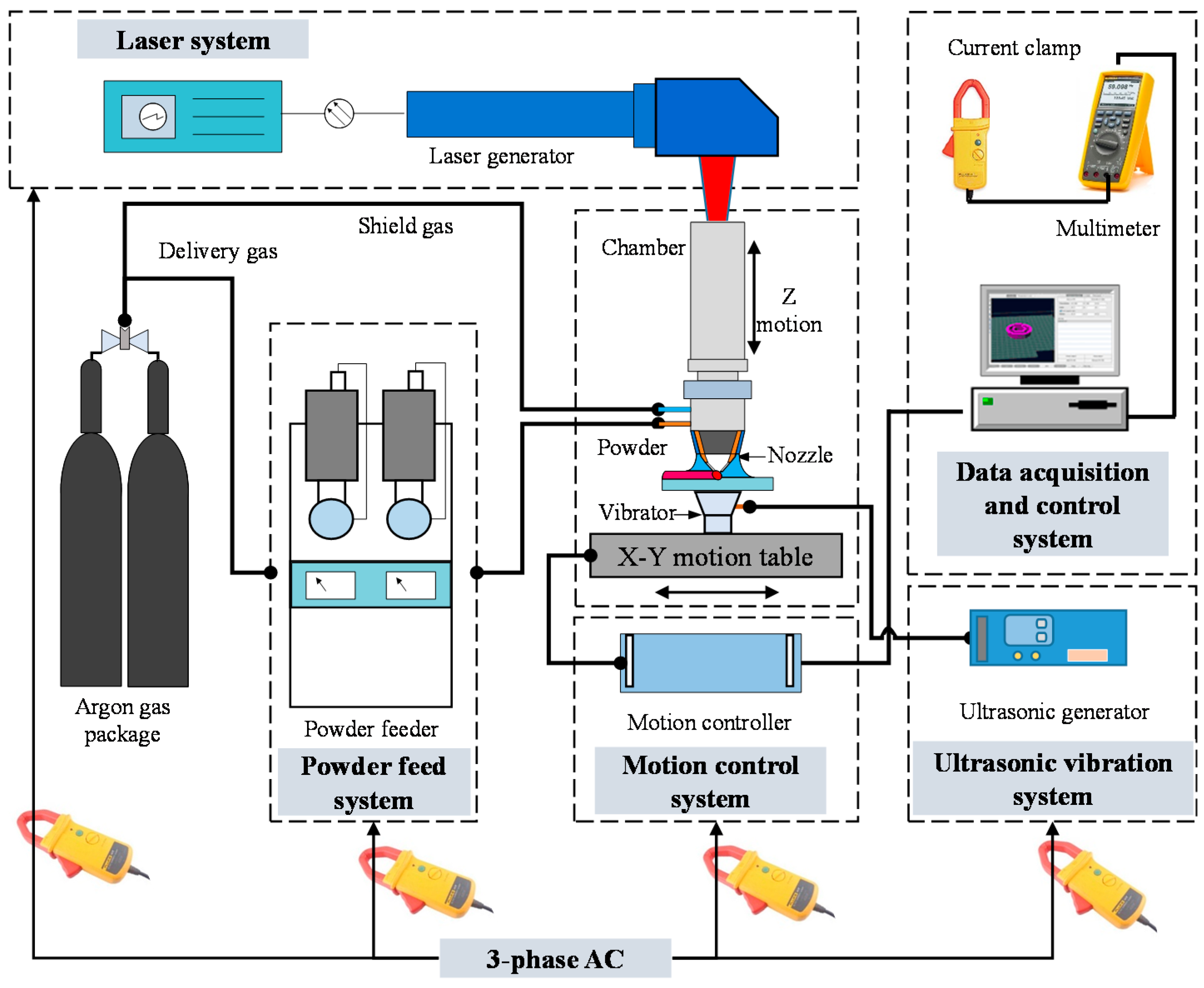
2.2. Experimental Set-Up

The experiment was carried out using an Optomec LENS 450 Workstation (Optomec Inc, Albuquerque, NM, USA), equipped with a high-powered IPG 400 W fiber laser (IPG Photonics, Oxford, MA, USA), a pneumatic powder delivery system, and a computer-controlled motion system. The powder feeder system is controlled by computer and motorized with revolutions-per-minute adjustment to meter the amount of powder flow. The powder material is deposited onto the substrate conveyed by an argon protective gas through the coaxial nozzles on a four-jet deposition head. A high-power laser is used to melt metal powder at the focus of the laser beam and the motion table is moved to fabricate the object layer by layer. The illustration of the complete LENS system is shown in Figure 1.
Three modules of the LENS system will require energy input: (1) laser power system, (2) powder feed system, and (3) motion control system. During the powder deposition process, each module requires one power cord (#1–#3). The ultrasonic vibration system is composed of an ultrasonic generator and a vibrator (frequency: 26.5 kHz). The fourth power cord (#4) is needed for the energy supply for the system, and the vibration system will only work during the ultrasonic vibration test.
The relationship between input variables (laser power, scanning speed, and powder feed rate) and overall energy consumption is investigated through a single factor experiment. The values of the variables are shown in Table 2.

2.3. Date Collection

A data acquisition system is set up for the measurement of voltage and current of power supply. The system includes a current clamp (Fluke i410, Fluke Corporation, Everett, WA, USA), a multi-meter (Fluke 289), and a computer with Fluke-View Forms Software. Totally, 16 blocks are deposited and the size and shaping of the blocks is shown in Figure 2. Three replications of currents measurement are documented for each combination of parameter, and the block size, process time, currents measured as well as energy consumption is shown in Table 3.

2.4. Energy Consumption Measurement

The amount of electricity used in the LENS is measured when depositing a block (the base area of the block is 7.62 × 7.62 mm2) onto the substrate material. The energy consumption of unit deposition volume (ECUDV, in J/mm3) is a measure for the averaged applied energy per volume of material during the deposition of a block:
E = P T V = U [ I l ( T t T i ) + ( I f + I s + I u v ) T t ] S × h
where E is the volumetric energy input, J/mm3; P is the input power, W; U is the system voltage, 240 V; T is the process time, s; Tt is the total time, s; Ti is the idling time, s; Il is the current of the laser system, amps; If is the current of the powder feeder system, amps; Is is the current of the motion control system, amps; Iuv is the current of the ultrasonic vibration system, amps; S is the bottom area of the block, 7.62 × 7.62 mm2; and h is the height of the block, mm (measured by caliper).
In Equation (1), only Il, If, Is, and the height of the deposited block are needed to be measured. The power consumption of the LENS system P can be calculated by multiplying the system voltage and the system current. During the Ti, the laser will be shut off and the system and powder feed rate system are still working. Due to the effect of input variables, the actual height (as measured) of the block is different from the theoretical height (1.727 mm as calculated by multiplying the number of layers and the theoretical layer thickness which has been input in the software) after the powder deposition process; therefore, both the theoretical energy consumption value (E1), which is calculated with the theoretical height of the deposited block, and the actual energy consumption value (E2), which is calculated with the actual height of the deposited block, are documented during the experiment.
The microhardness was measured using a Vickers microhardness tester (900-390A Phase II, Metal-Testers Inc., Nanuet, NY, USA), and the microhardness tests were repeated five times on each sample. The porosities of the fabricated blocks were observed using a field emission scanning electron microscopy (FE-SEM, S4300, Hitachi Co., Tokyo, Japan).

3. Results and Discussion

3.1. Effects of Input Variables

The effects of input variables (laser power, powder feed rate, and scanning speed) on the overall energy consumption are shown in Figure 3, Figure 4 and Figure 5, respectively. When the input variables changed, the theoretical and actual values of energy consumption presented a different trend. This is because the actual height of the volume is not the same as the software settings due to the combined impact of the input variables. The actual height value is always higher than the theoretical height value; therefore, the mean value of the actual energy consumption is lower than the theoretical value.
The effects of laser power on both the theoretical and actual ECUDV values are shown in Figure 3. Theoretically, the energy consumption should be increasing when the power input increases (as is shown in Figure 3a); however, the energy consumption decreases when the laser power increases from 275 W to 300 W. This is possibly because the powders are not totally melted under 300 W, and the porosity is higher which causes a bigger block. When the laser power keeps increasing, the powders are totally melted, and the unit energy consumption increased as is theoretically indicated (as is shown in Figure 3b). The porosity of the surface layer under different laser power is shown in Figure 4.
The effect of the scanning speed on the overall energy consumption is shown in Figure 5. When the scanning speed increased from 6.35 mm/s to 12.7 mm/s, the unit energy consumption decreased significantly (as is shown in Figure 5a). That is because when the scanning speed increases, the process time is reduced, and the total energy input is reduced correspondingly from a theoretical standpoint. However, when the scanning speed changes from 8.47 mm/s to 12.7 mm/s, there is not enough time for the powders to be totally melted [28]; therefore, the actual volume of the deposited block decreases, and it becomes the dominant factor, which causes the increase of the unit energy consumption (as is shown in Figure 5b).
For the effect of the powder feed rate, Equation (1) suggests that it will not affect the volume of the final block; therefore, the unit energy consumption increased slightly (as is shown in Figure 6a). Actually, the height of the deposited block will be significantly increased when the powder feed rate increases from 2.5 rpm to 4 rpm, which causes the increase of the volume; therefore, the actual unit energy consumption value decreases (as is shown in Figure 6b).
The result of the microhardness test is shown in Figure 7. It is evident that there is little difference in the microhardness values among the deposited blocks, except for sample 16, which has the highest microhardness value (273 HV1). It means that the quality of the part will not be reduced too much when considering the energy-saving opportunities by adjusting the parameters. Consequently, it is considered that taking into account the influence of all three factors (laser power, scanning speed and powder feed rate) together can make it possible to reduce the energy consumption and, at the same time, maintain a good part quality. The results of ECUDV in Figure 3, Figure 4 and Figure 6 suggest that the optimal combination of the parameters for Inconel 718 as a material to reduce the energy consumption is a laser power of 300 W, a scanning speed of 8.47 mm/s and a powder feed rate of 4 rpm. The measured ECUDV with the above parameter combination is 665.30 J/mm3, which is slightly smaller than the minimal value (683.95 J/mm3) in Table 3. It should be noted that the blocks cannot have the same quality under different parameter combinations, due to the limitations of the equipment; currently, only the microhardness test is performed to make the energy consumption analysis more meaningful. In the future, other mechanical properties will be tested, such as the scratch test, and the comprehensive and tensile test.

3.2. Effect of Ultrasonic Vibration

The effects of the ultrasonic vibration on the energy consumption for the entire LENS system are shown in Figure 8. Comparing the regular process 270 (W/O) (laser power: 270 W, without ultrasonic vibration) and ultrasonic vibration–assisted process 270 (W) (laser power: 270 W, with ultrasonic vibration), the theoretical unit energy consumption increases because a separate system is added and the fourth cord is needed to provide the energy for the ultrasonic vibration system; however, the actual value of ECUDV is reduced. The reason is that when ultrasonic vibration is applied in the LENS process, the optical absorptivity increases and the final volume of the deposited block is larger than the regular process. When comparing the microhardness of the top surface of the deposited block, the average microhardness value of 270 (W) is 325.9 HV1 which is higher than that of 350 (W/O), as is shown in Figure 9. Moreover, the ECUDV at 270 (W) is less than that of 350 (W/O). The results suggest that the ultrasonic vibration–assisted process can not only improve the clad quality, but can also reduce the energy consumption of the entire system.

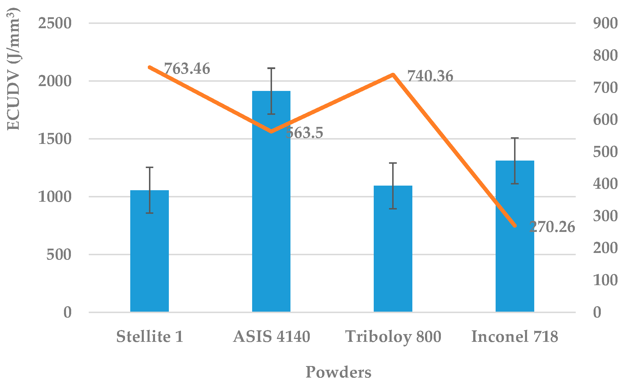
3.3. Effect of Powder Materials

Due to the different property of the powders, the best clad quality will occur at different conditions (parameter combinations). Given the condition that the final shaping of the blocks is the best, the input parameters selected for each kind of powder is shown in Table 4. The effect of the powders on the unit energy consumption and microhardness is examined and the result is shown in Figure 10. AISI 4140 will cause the highest energy consumption, followed by Inconel 718, Triboloy 800 and Stellite 1. The reason is that, for different powders, the power absorption is different (AISI 4140 has the lowest laser power absorption rate of the selected powders), and the interaction of the power and powder is also different, which brings about different energy requirements. The microhardness of the fabricated parts is Stellite 1 > Triboloy 800 > AISI 4140 > Inconel 718, which suggests that it is possible to select powders which can not only cause less energy consumption, but also provide a better part quality, such as Stellite 1 and Triboloy 800.

4. Conclusions

This paper analyzed the energy consumptions of the LENS process, and the effect of the input variables (laser power, scanning speed and powder feed rate) and powder particles on energy consumption as well as the potential benefit of energy reduction through the ultrasonic vibration–assisted LENS process are investigated in detail. The following conclusions can be drawn from the study.
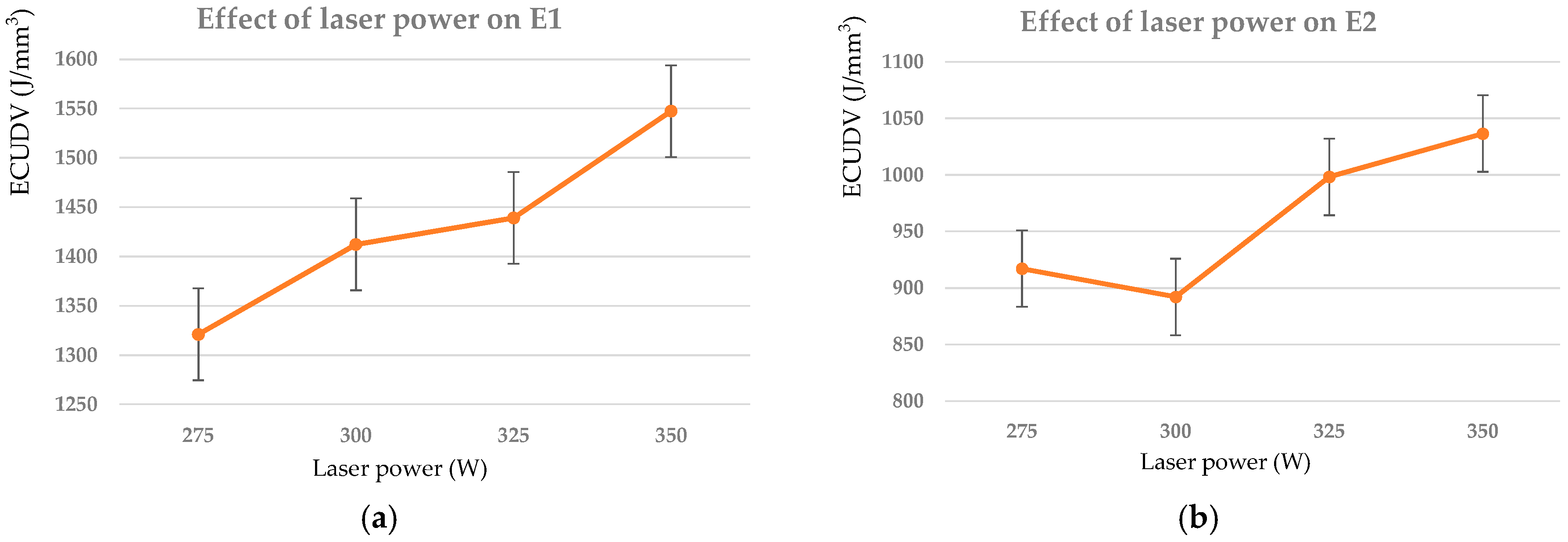
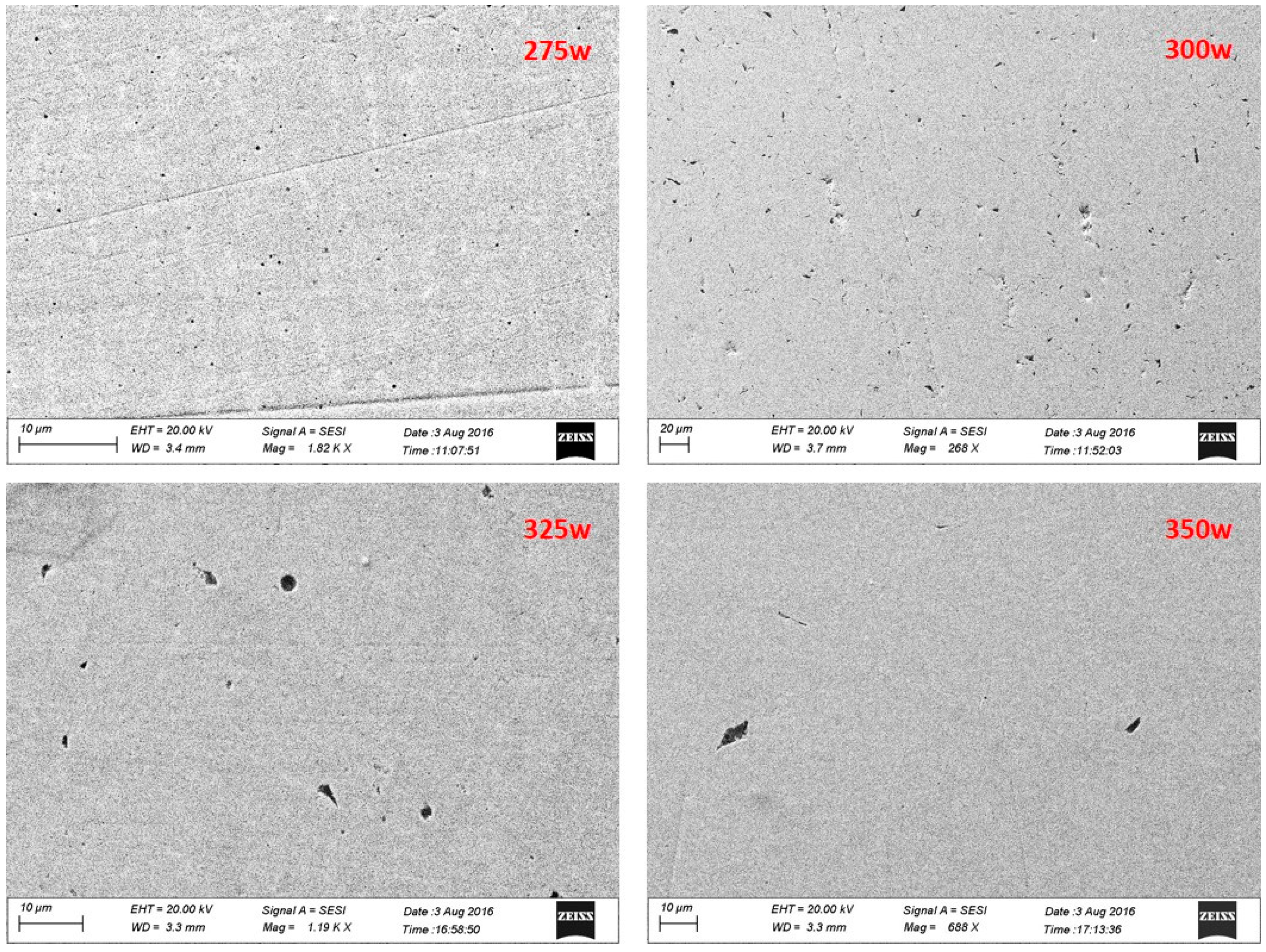
  • The ECUDV decreases when the laser power increases from 275 W to 300 W since the powders are not totally melted and the porosity value is higher, which causes a bigger block. When the laser power keeps increasing, the powders are totally melted, and the unit energy consumption increased as is theoretically indicated.
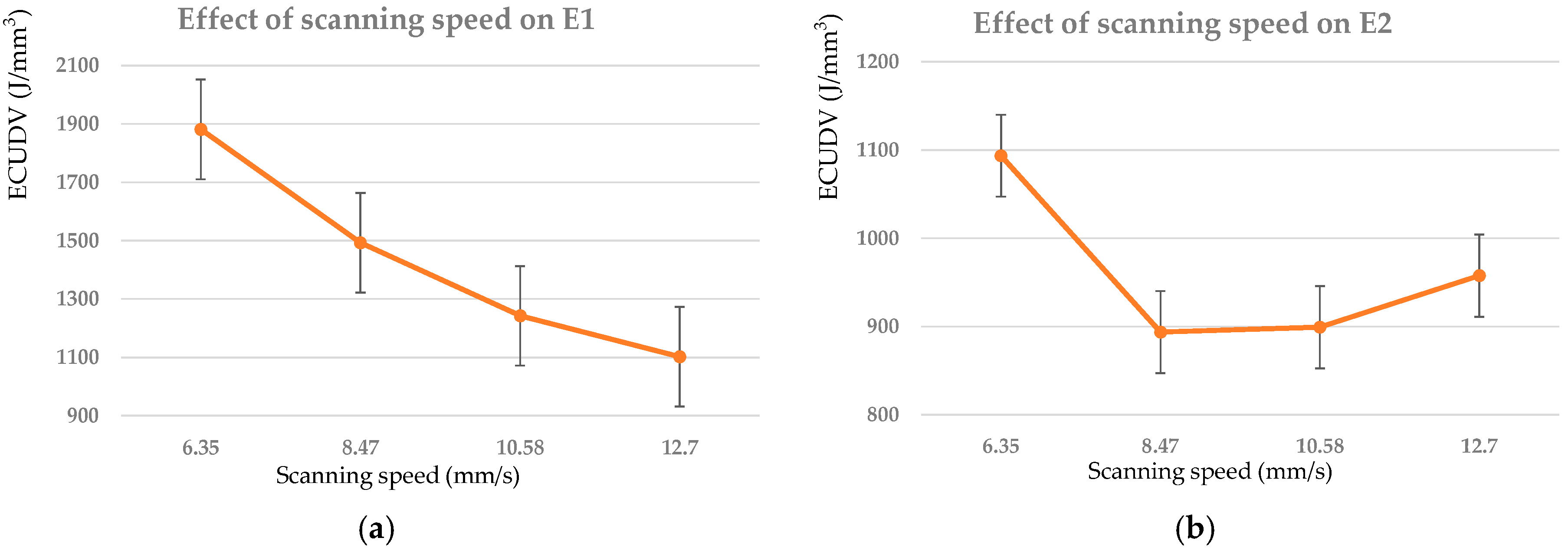
  • When the scanning speed changes from 8.47 mm/s to 12.7 mm/s, the process time will be reduced and there is not enough time for the powders to be totally melted; therefore, the actual volume of the deposited block decreases, which causes the increase of the unit energy consumption.
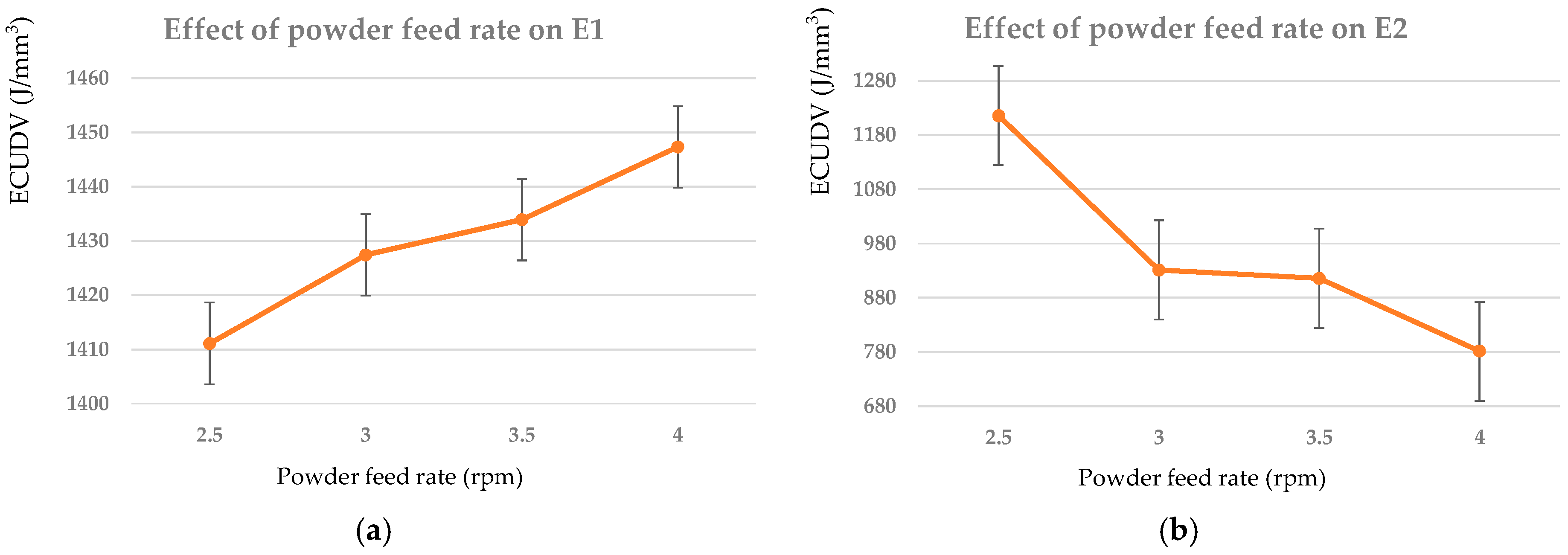
  • The height of the deposited block is significantly increased when the powder feed rate increases from 2.5 rpm to 4 rpm, which causes the increase of the volume; therefore, the actual unit energy consumption value decreases.
  • It is possible to reduce the energy consumption and, at the same time, maintain a good part quality (microhardness). The optimal parameter combination to reduce the ECUDV is: a laser power of 300 W, a scanning speed of 8.47 mm/s and a powder feed rate of 4 rpm.
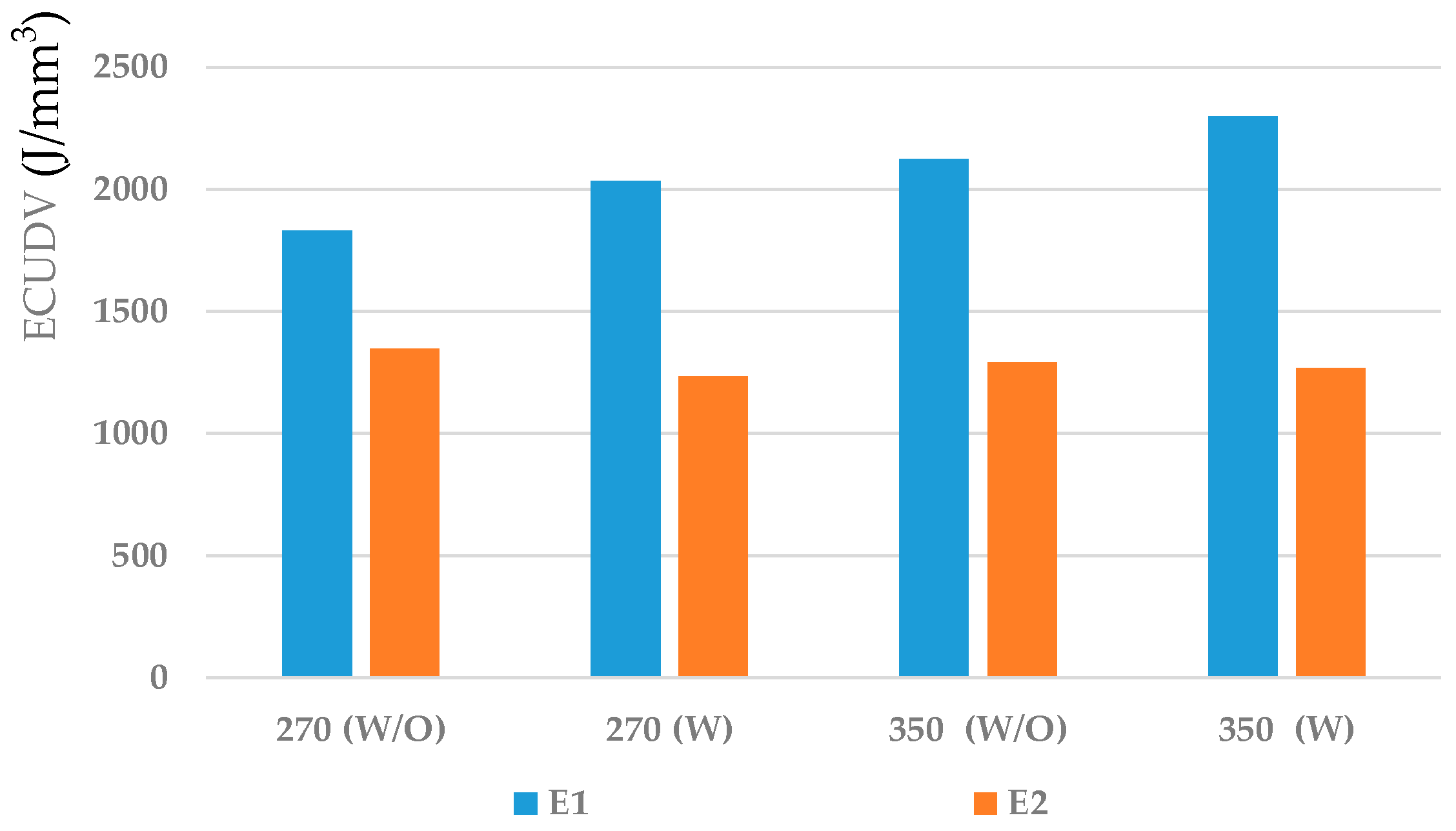
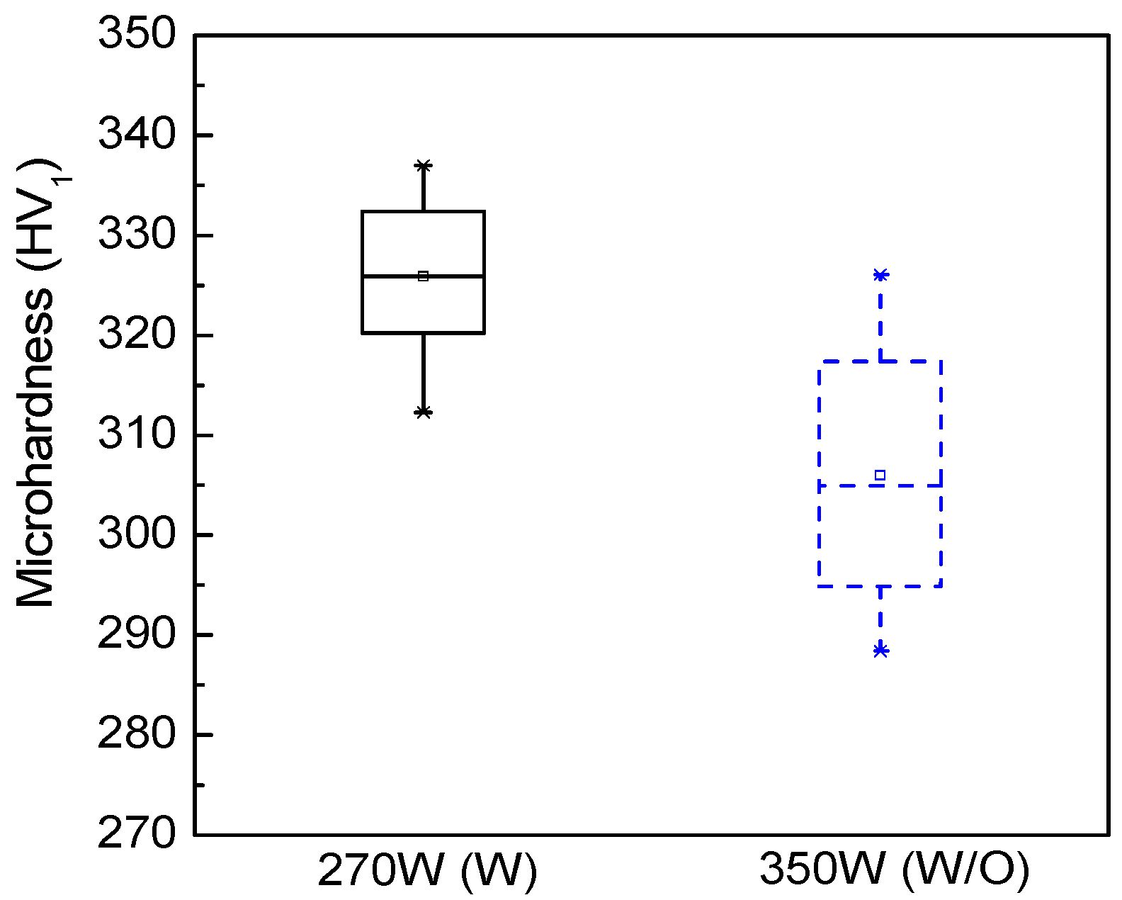
  • The ultrasonic vibration–assisted LENS process can not only increase the part quality, but also reduces the actual value of the energy consumption.
  • The type of powder will affect the energy consumption in the LENS process; AISI 4140 will cause the highest ECUDV, followed by Inconel 718, Triboloy 800 and Stellite 1. The microhardness of the fabricated parts is Stellite 1 > Triboloy 800 > AISI 4140 > Inconel 718, which suggests that it is possible to select powders which can not only cause less energy consumption, but also provide a better cald quality, such as Stallite 1 and Triboloy 800.

Acknowledgments

The research leading to these results has received research funds from the National Program on Key Basic Research Project (973 Program) of China with Grant No. 2011CB013406. The authors also would like to extend the acknowledgements to the Foundation of the Whitacre College of Engineering and the Office of Vice President for Research at Texas Tech University.

Author Contributions

Zhichao Liu conceived and designed the experiments; Qiuhong Jiang and Yingge Zhou performed the experiments; Zhichao Liu and Fuda Ning analyzed the data; Weilong Cong, Tao Li and Hongchao Zhang contributed reagents/materials/analysis tools; Zhichao Liu wrote the paper.

Conflicts of Interest

The authors declare no conflict of interest.

References

  1. Xu, M.; Li, J.; Jiang, J.; Li, B. Influence of powders and process parameters on bonding shear strength and micro hardness in laser cladding remanufacturing. Procedia CIRP 2015, 29, 804–809. [Google Scholar] [CrossRef]
  2. Atwood, C.; Griffith, M.; Harwell, L.; Schlienger, E.; Ensz, M.; Smugeresky, J.; Romero, T.; Greene, D.; Reckaway, D. Laser Engineered Net Shaping (LENSTM): A Tool for Direct Fabrication of Metal Parts; LENS™ Project Team, Sandia National Laboratories: Albuquerque, NM, USA, 1998. [Google Scholar]
  3. Jeantette, F.P.; Keicher, D.M.; Romero, J.A.; Schanwald, L.P. Method and system for producing complex-shape objects. U.S. Patent 6,046,426, 4 April 2000. [Google Scholar]
  4. Pei, Y.T.; De Hosson, J.T.M. Functionally graded materials produced by laser cladding. Acta Mater. 2000, 48, 2617–2624. [Google Scholar] [CrossRef]
  5. Dong, S.; Yan, S.; Xu, B.; Wang, Y.; Ren, W. Laser cladding remanufacturing technology of cast iron cylinder head and its quality evaluation. J. Acad. Armored Force Eng. 2013, 27, 90–93. [Google Scholar]
  6. Santos, E.C.; Shiomi, M.; Osakada, K.; Laoui, T. Rapid manufacturing of metal components by laser forming. Int. J. Mach. Tools Manuf. 2006, 46, 1459–1468. [Google Scholar] [CrossRef]
  7. Tabernero, I.; Lamikiz, A.; Martínez, S.; Ukar, E.; Figueras, J. Evaluation of the mechanical properties of Inconel 718 components built by laser cladding. Int. J. Mach. Tools Manuf. 2011, 51, 465–470. [Google Scholar] [CrossRef]
  8. Majumdar, J.D.; Pinkerton, A.; Liu, Z.; Manna, I.; Li, L. Mechanical and electrochemical properties of multiple-layer diode laser cladding of 316L stainless steel. Appl. Surf. Sci. 2005, 247, 373–377. [Google Scholar] [CrossRef] [Green Version]
  9. Qi, H.; Azer, M.; Ritter, A. Studies of standard heat treatment effects on microstructure and mechanical properties of laser net shape manufactured Inconel 718. Metall. Mater. Trans. A. 2009, 40, 2410–2422. [Google Scholar] [CrossRef]
  10. Zhao, X.; Chen, J.; Lin, X.; Huang, W. Study on microstructure and mechanical properties of laser rapid forming Inconel 718. J. Mater. Sci. Eng. A 2008, 478, 119–124. [Google Scholar] [CrossRef]
  11. Zhong, M.; Liu, W.; Yao, K.; Goussain, J.C.; Mayer, C.; Becker, A. Microstructural evolution in high power laser cladding of Stellite 6+WC layers. Surf. Coat Technol. 2002, 157, 128–137. [Google Scholar] [CrossRef]
  12. Nurminen, J.; Näkki, J.; Vuoristo, P. Microstructure and properties of hard and wear resistant MMC coatings deposited by laser cladding. Int. J. Refract. Met. Hard Mater. 2009, 27, 472–478. [Google Scholar] [CrossRef]
  13. Niu, H.J.; Chang, I.T.H. Microstructural evolution during laser cladding of M2 high-speed steel. Metall. Mater. Trans. A 2000, 31, 2615–2625. [Google Scholar] [CrossRef]
  14. Dubourg, L.; Ursescu, D.; Hlawka, F.; Cornet, A. Laser cladding of MMC coatings on aluminium substrate: Influence of composition and microstructure on mechanical properties. Wear 2005, 258, 1745–1754. [Google Scholar] [CrossRef]
  15. Zheng, B.; Zhou, Y.; Smugeresky, J.E.; Schoenung, J.M.; Lavernia, E.J. Thermal behavior and microstructural evolution during laser deposition with laser-engineered net shaping: Part I. Numerical calculations. Metall. Mater. Trans. A 2008, 39, 2228–2236. [Google Scholar] [CrossRef]
  16. Zheng, B.; Zhou, Y.; Smugeresky, J.E.; Schoenung, J.M.; Lavernia, E.J. Thermal behavior and microstructure evolution during laser deposition with laser-engineered net shaping: Part II. Experimental investigation and discussion. Metall. Mater. Trans. A 2008, 39, 2237–2245. [Google Scholar] [CrossRef]
  17. Griffith, M.L.; Ensz, M.T.; Puskar, J.D.; Robino, C.V.; Brooks, J.A.; Philliber, J.A.; Smugeresky, J.E.; Hofmeister, W.H. Understanding the microstructure and properties of components fabricated by laser engineered net shaping (LENS). Mater. Res. Soc. Symp. Proc. 2000, 625. [Google Scholar] [CrossRef]
  18. Ye, R.; Smugeresky, J.E.; Zheng, B.; Zhou, Y.; Lavernia, E.J. Numerical modeling of the thermal behavior during the LENS® process. J. Mater. Sci. Eng. A 2006, 428, 47–53. [Google Scholar] [CrossRef]
  19. Wang, L.; Felicelli, S. Analysis of thermal phenomena in LENS™ deposition. J. Mater. Sci. Eng. A 2006, 435, 625–631. [Google Scholar] [CrossRef]
  20. Unocic, R.R.; DuPont, J.N. Process efficiency measurements in the laser engineered net shaping process. Metall. Mater. Trans. B 2004, 35, 143–152. [Google Scholar] [CrossRef]
  21. Pinkerton, A.J.; Li, L. An analytical model of energy distribution in laser direct metal deposition. Proc. Inst. Mech. Eng. B J. Eng. Manuf. 2004, 218, 363–374. [Google Scholar] [CrossRef]
  22. Gedda, H.; Powell, J.; Wahlström, G.; Li, W.B.; Engström, H.; Magnusson, C. Energy redistribution during CO2 laser cladding. J. Laser Appl. 2002, 14, 78–82. [Google Scholar] [CrossRef]
  23. Liu, W.; Dupont, J.N. In-situ reactive processing of nickel aluminides by laser-engineered net shaping. Metall. Mater. Trans. A 2003, 34, 2633–2641. [Google Scholar] [CrossRef]
  24. Picas, J.A.; Xiong, Y.; Punset, M.; Ajdelsztajn, L.; Forn, A.; Schoenung, J.M. Microstructure and wear resistance of WC–Co by three consolidation processing techniques. Int. J. Refract. Met. Hard Mater. 2009, 27, 344–349. [Google Scholar] [CrossRef]
  25. Ning, F.D.; Cong, W.L. Microstructures and mechanical properties of Fe-Cr stainless steel parts fabricated by ultrasonic vibration-assisted laser engineered net shaping process. Mater. Lett. 2016, 179, 61–64. [Google Scholar] [CrossRef]
  26. Dong, S.; Ma, Y.; Xu, B.; Han, W. Current status of material for laser cladding. Mater. Rev. 2006, 6, 5–13. [Google Scholar]
  27. Sun, Z.; Ion, J.C. Laser welding of dissimilar metal combinations. J. Mater. Sci. 1995, 30, 4205–4214. [Google Scholar] [CrossRef]
  28. Fathi, A.; Toyserkani, E.; Khajepour, A.; Durali, M. Prediction of melt pool depth and dilution in laser powder deposition. J. Phys. D Appl. Phys. 2006, 39, 2613–2623. [Google Scholar] [CrossRef]
Figure 1. Illustration of experimental set-up.
Energies 09 00763 g001
Figure 2. The dimension and shaping of the deposited blocks.
Energies 09 00763 g002
Figure 3. Effect of laser power: (a) theoretical value and (b) actual value. Powder: Inconel 718.
Energies 09 00763 g003
Figure 4. Porosity of the surface layer under different laser power (scanning speed: 8.47 mm/s, powder feed rate: 4 rpm).
Energies 09 00763 g004
Figure 5. Effect of scanning speed: (a) theoretical value and (b) actual value. Powder: Inconel 718.
Energies 09 00763 g005
Figure 6. Effect of powder feed rate: (a) theoretical value and (b) actual value. Powder: Inconel 718.
Energies 09 00763 g006
Figure 7. Result of microhardness test for the deposited blocks.
Energies 09 00763 g007
Figure 8. Effect of ultrasonic vibration on energy consumption (E1: theoretical value, E2: actual value, powder: Inconel 718, scanning speed: 8.47 mm/s, powder feed rate: 2.5 rpm).
Energies 09 00763 g008
Figure 9. Microhardness of the top surface of deposited block with/without ultrasonic vibration (powder: Inconel 718; scanning speed: 8.47 mm/s; powder feed rate: 2.5 rpm).
Energies 09 00763 g009
Figure 10. Effect of powder materials on energy consumption and microhardness.
Energies 09 00763 g010
Table 1. Properties of selected materials. AISI: American Iron and Steel Institute.
TypeCladding MaterialParticle Size (μm)Hardness (HRC)UTS (MPa)Density (g/cm³)
Ni-basedInconel 71844/12542–4412418.19
Co-basedStellite 145/15050–5811958.69
Tribaloy t-80053/14955–6017788.64
Fe-basedAISI 414044/10531–391000–12007.85
Table 2. Values of input variables.
VariableValueAttribute
Laser power (W)275, 300, 325, 350Variable
Scanning speed (mm/s)6.35, 8.47, 10.58, 12.7Variable
Powder feed rate (rpm)2.5, 3.0, 3.5, 4.0Variable
Layer thickness (mm)0.43Constant
Gas flow rate (L/min)6Constant
Number of layers4Constant
Table 3. Results of the block volume, process time, currents measured, as well as energy consumption versus parameters combinations.
Laser PowerScanning SpeedPowder Feed RateHeightVolumeTotal TimeIdle TimeProcess TimeCurrent 1Current 2Current 3AverageVoltageE1E2
LaserFeedControlLaserFeedControlLaserFeedControlLaserFeedControl
Wmm/srpmmmmm3sssAAAAAAAAAAAAVJ/mm3J/mm3
2756.352.52.54147.471324.097127.9040.631.84.20.621.794.20.621.784.130.621.79240.001729.771378.79
2758.4733.32192.571043.073100.934.20.631.794.20.611.814.20.621.84.200.621.80240.001379.31841.99
27510.583.53.04176.70862.45883.544.30.641.824.20.631.844.10.631.814.200.631.82240.001147.73763.55
27512.743.04176.50762.04873.954.30.661.834.20.651.814.30.621.834.270.641.82240.001026.96683.95
3006.3534.05235.141324.097127.904.60.611.824.60.621.834.70.661.854.630.631.83240.001873.81936.73
3008.472.52.86166.051043.073100.934.60.621.834.60.611.844.60.631.854.600.621.84240.001470.231040.79
30010.5843.49202.82862.45883.544.60.641.854.60.661.864.60.651.844.600.651.85240.001223.57709.14
30012.73.52.48144.18762.04873.954.70.621.814.60.631.814.70.611.84.670.621.81240.001081.15881.44
3256.353.53.41197.981324.097127.904.70.621.794.70.621.824.80.611.814.730.621.81240.001889.151121.65
3258.4743.83222.371043.073100.934.80.631.814.80.621.84.80.631.794.800.631.80240.001504.36795.24
32510.582.52.25130.64862.45883.544.80.891.794.80.621.784.70.641.794.770.721.79240.001252.581127.12
32512.732.37137.60762.04873.954.90.581.814.90.591.794.90.611.794.900.591.80240.001110.69948.83
3506.3544.40255.271324.097127.905.30.611.795.20.621.85.40.621.85.300.621.80240.002034.43936.84
3508.473.53.65212.111043.073100.935.40.61.795.30.621.85.40.61.825.370.611.80240.001617.59896.45
35010.5832.73158.70862.45883.545.40.61.785.40.611.795.50.61.785.430.601.78240.001345.81996.86
35012.72.51.83106.44762.04873.955.40.611.795.40.611.785.50.61.795.430.611.79240.001191.731316.08
Note: Current 1, 2 and 3 represent the replications of the current measurement.
Table 4. Input parameters selected for each kind of powder.
PowdersLaser Power (W)Scanning Speed (mm/s)Powder Feed Rate (rpm)
Stellite 13508.472.5
AISI 41403808.472
Triboloy 8003608.472
Inconel 71835012.72.5

