


Abstract
This paper investigates the combustion phasing control of natural gas-diesel engines. In this study, the combustion phasing is influenced by manipulating the start and the duration of the diesel injection. Instead of using both degrees of freedom to control the center of combustion only, we propose a method that simultaneously controls the combustion phasing and minimizes the amount of diesel used. Minimizing the amount of diesel while keeping the center of combustion at a constant value is formulated as an optimization problem with an equality constraint. A combination of feedback control and extremum seeking is used to solve this optimization problem online. The necessity to separate the different time scales is discussed and a structure is proposed that facilitates this separation for this specific example. The proposed method is validated by experiments on a test bench.
1. Introduction
1.1. Motivation
Almost 17% of the worldwide emissions are caused by road transportation [1]. According to [2], road transport demand will nearly double between 2009 and 2035. The major part of road transportation is propelled by internal combustion engines. The reduction of the emissions of those engines is therefore one of the major tasks of researchers in the field of automotive engines. A promising concept for dealing with this problem is the natural gas-diesel engine, which is a dual-fuel engine where natural gas is used as the basic fuel in a compression ignition engine. A small amount of diesel is used to control the combustion.
The energy-specific emissions of natural gas are 20%–25% lower than those of gasoline or diesel [3], depending on the quality of the natural gas. Methane, the main component of natural gas, is highly resistant to knocking. It thus enables the use of natural gas in a compression ignition engine with its high compression ratio, which enables high efficiencies. Knocking did not occur in the experiments presented in [4] with a compression ratio of 17 and an indicated mean effective pressure of 26 bar.
The natural gas-diesel engine has the potential of reducing emissions without the need for a lean de- system [4,5]. The combustion of natural gas-diesel engines has been studied thoroughly, see for example [6,7,8,9,10].
This paper deals with the combustion phasing control of a natural gas-diesel engine. A calibration method is proposed that minimizes the amount of diesel used, while the center of combustion (), as an indicator of the combustion phasing, is kept at its reference value. The center of combustion is the crank angle at which 50% of the fuel is burnt. Diesel is only used for the ignition process and the goal is to use as little diesel as possible because of the advantages of natural gas. The combustion process of a natural gas-diesel engine is complex and the combustion phasing is prone to several influences, such as the rate of exhaust gas recirculation (EGR). The proposed method changes the diesel injection in order to compensate for such influences.
1.2. Hardware
The system identification and the validation of the proposed method are carried out on an engine converted to natural gas-diesel operation. Some key data of the engine, originally a conventional diesel engine with common-rail diesel injection, variable-geometry turbo charger (VGT) and high-pressure EGR, is summarized in Table 1.
Table 1.
Specifications of the basic engine.
In order to convert the engine into a dual-fuel engine, a natural gas port fuel injection system is installed, as well as cylinder-pressure sensors in all cylinders. The cylinder-pressure sensors are used to estimate the center of combustion .
1.3. Overall Control Structure
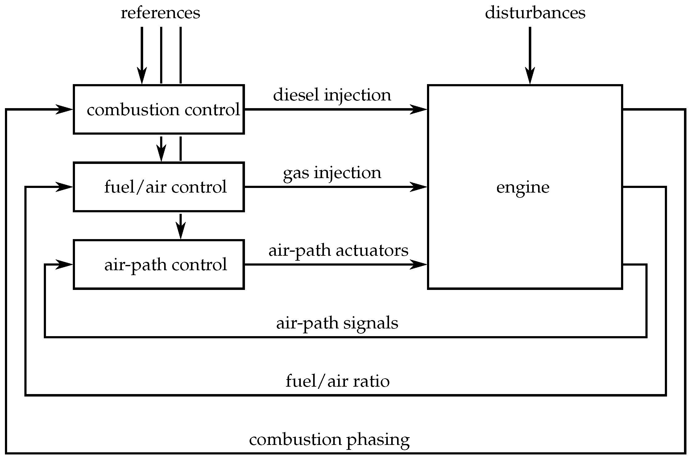
The natural gas-diesel engine provides many actuators, and thus a large number of degrees of freedom is available to influence the combustion. Furthermore, it is prone to several influences such as ambient air conditions or varying fuel qualities. Therefore, the use of feedback control thus is indispensable in order to keep the relevant variables at the desired set values. Figure 1 shows the overall control structure. The main control tasks of such an engine can be assigned to three controllers: the combustion controller, the fuel/air equivalence ratio controller and the air-path controller.
Typical controlled variables of the air-path are the level of EGR and the intake manifold pressure. The actuators the air-path controller uses to manipulate those controlled variables are the nozzles of the VGT, the EGR valve and the throttle. The fuel/air equivalence ratio controller changes the gas injection in order to manipulate the total fuel/air ratio as the controlled variable.
The combustion controller changes the diesel injection in order to manipulate the combustion phasing as the corresponding controlled variable and to compensate for other influences to the combustion phasing. The focus of this paper is the combustion phasing control using the degrees of freedom of the diesel injection, i.e., start and duration of injection. The other two control tasks mentioned above are common control problems for internal combustion engines and appropriate information can be found for example in [11,12,13,14].
Obviously, there are various other variables that affect the combustion phasing as well—for example, the fuel/air ratio or the EGR rate. However, those variables are either not directly controllable, or are reserved for other purposes. Therefore, in this study, the diesel injection timing and duration are used as a means to influence the combustion phasing. Using the control structure shown in Figure 1, the set values of the relevant variables such as the EGR rate, the intake manifold pressure and the total fuel/air ratio can be arbitrarily chosen, while the combustion phasing is maintained at the desired set value.
Figure 1.
Overall control structure: the combustion controller, the air-path controller and the fuel/air ratio controller serve as the three main controllers.
There are various other low level controllers that are also beyond the focus of this paper, such as the rail pressure controller of the diesel rail. The pressure of the diesel rail is maintained at a constant level of 500 bar in order to allow low amounts of diesel to be injected.
1.4. System Description
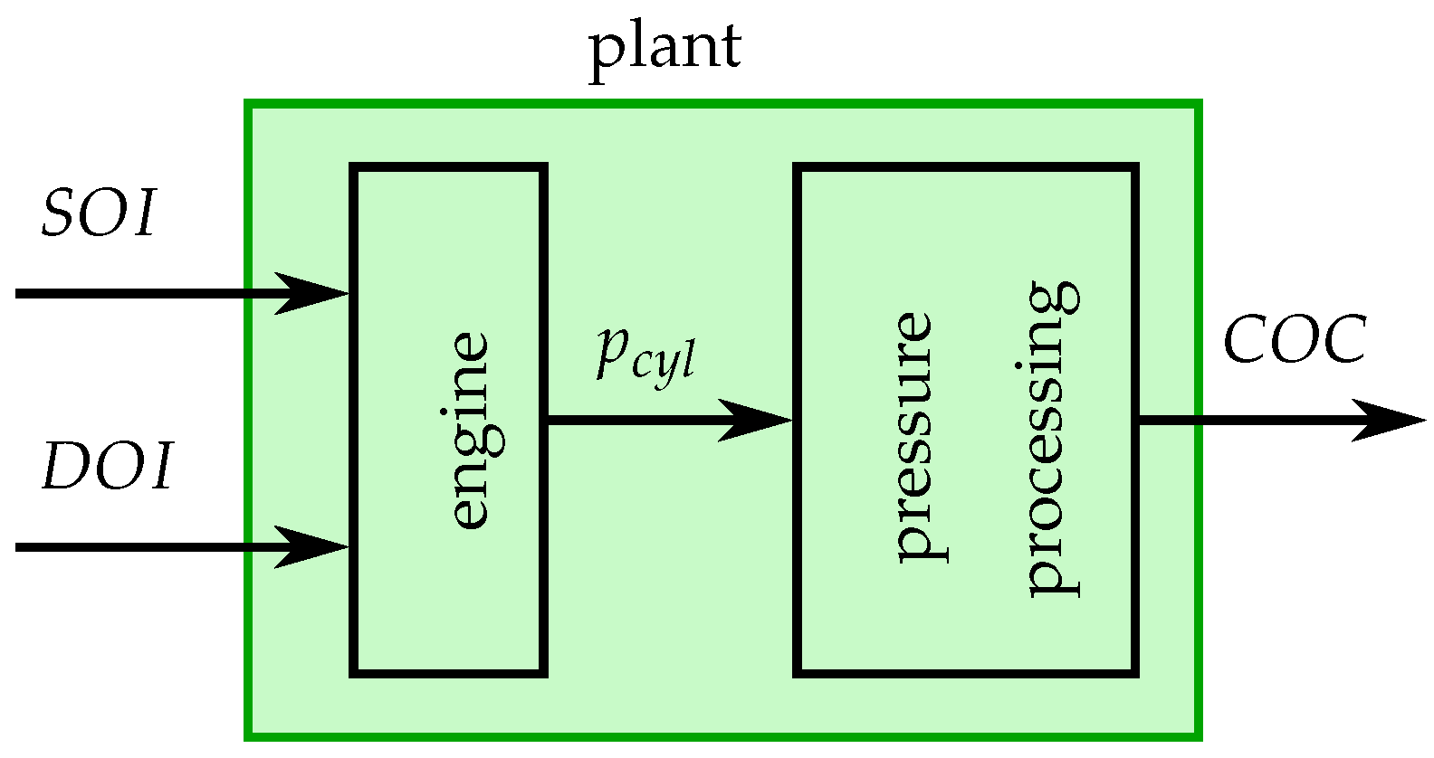
If the operating conditions are hold constant, the combustion phasing of a natural gas-diesel engine can be manipulated by changing the start and the duration of the diesel injection and , respectively. The combustion phasing is indicated by the center of combustion , which is calculated online for each cylinder and for each engine cycle based on the in-cylinder pressure measurements. Figure 2 shows the structure of the plant that has two inputs ( and ) and one output ().
Figure 2.
Plant structure: The center of combustion as output and the start and the duration of the diesel injection ( and ) as inputs, respectively.
The plant is modeled as an inherently discrete-time system:
The variable z is used for the time-shift operation, i.e.,:
where x is an arbitrary signal. The variable k is used as the time index of the discrete-time signals, which in this case is the index of the engine cycles. All other influences, for example the engine temperature, are assumed to be changing slowly and thus can be compensated using feedback control, as introduced below in this paper. The unit delay in Equation (1) is due to the pressure processing that takes place after the combustion process.
Figure 3 shows the center of combustion as a function of the start of injection for distinct values of . The operating point is given in Table 2.
Figure 3.
Stationary measurements of the center of combustion for four distinct values of , where the start of injection is varied.
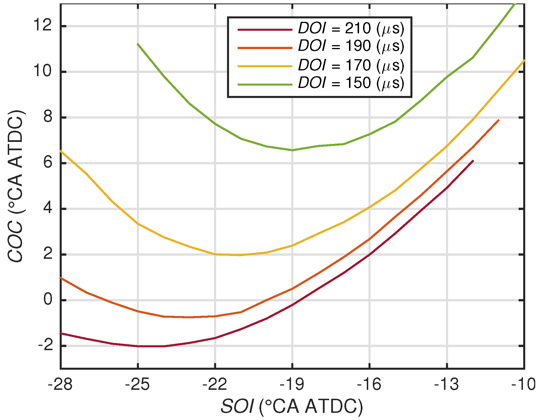
Table 2.
Operating point used for the system identification.
The relationship between the duration and the center of combustion is unique. An increase of the duration for a constant start of injection advances the center of combustion , i.e., the center of combustion is advanced if more diesel is injected.
The relationship between the start of injection and the center of combustion for a constant duration is more complicated. There exists a minimum achievable center of combustion for each constant duration of injection . On the right side of the minimum, the center of combustion is retarded if the start of injection is retarded. To the left of the minimum, the center is retarded if the start is advanced. In other words, the local gradient from the input to the output changes its sign depending on the . This sign change is typical for natural gas-diesel engines [4,7,10]. It can be explained by the strong dilution of the diesel if it is injected very early, which leads to a low local equivalence ratio towards the end of the compression phase and therefore to a longer ignition delay of the diesel [15]. The sign change can also be observed in other dual-fuel engines that use diesel to ignite the mixture, for example, if gasoline or ethanol is used as the primary fuel, see [15] or [16], respectively. The method proposed in this paper can be applied to all engines that feature this sign change. The system analysis used in this research is described in detail in [17,18].
1.5. Problem Formulation
The major influence on the efficiency of the combustion is the combustion phasing [19,20,21]. This means that the set value of the center of combustion should be set at a constant value, such that the mechanical work is maximized for a given operating point. The center of combustion that maximizes the efficiency is usually located around crank angle (CA) after top dead center (ATDC) (see for example [19,20,21]). The desired center of combustion for a constant operating point is assumed to be given. The set value for the center of combustion is hereinafter referred to as .
The system shown in Figure 2 has two inputs and one output, i.e., two degrees of freedom to manipulate one output, which means that the center of combustion as the system output is over-determined. This motivates the use of the two degrees of freedom not only to control one output but also for an additional purpose. Natural gas is the primary fuel because of its advantages, as mentioned above, while diesel is only used to control the combustion. Therefore, it would be reasonable to use the second degree of freedom to minimize the amount of diesel used while keeping the center of combustion at a constant value.
The problem can mathematically be formulated as an optimization problem with an equality constraint that has the following general form:
For the sake of simplicity, the time index k is omitted. The equality constraint ensures that the center of combustion remains at its set value . The function is therefore given by Equation (1) and the set value :
The cost function is the amount of diesel used, which, for a constant rail pressure, is a monotonically increasing function of the duration of the diesel injection , i.e., the longer the injection lasts, the larger is the amount of diesel used. Minimizing the amount of diesel used is therefore equivalent to minimizing the duration of injection , which means that the cost function is given as:
The problem thus can be rewritten as:
1.6. Contribution
A method is presented that combines feedback combustion control with extremum seeking in order to solve the problem given by Equations (7) and (8), i.e., the method minimizes the amount of diesel used in a natural gas-diesel engine while the combustion phasing is kept constant. The proposed method can be used for engine calibration. In the case of feedback combustion control using cylinder pressure sensors, the calibration of the feedback combustion controllers (see Section 2) can be facilitated using the proposed method. Another application may be online minimization, e.g., if the system ages, the fuel quality changes, or if the ambient air conditions change.
1.7. Structure
2. Feedback Combustion Control
The combustion phasing in a natural gas-diesel engine is sensitive to unmeasurable disturbances, for example production tolerances, aging, varying fuel qualities or changing ambient conditions. Such disturbances can best be compensated using feedback control [17,18]. Pure feedforward combustion control may lead to an unexpected or unstable behavior. Feedback combustion control investigations using the in-cylinder pressure signal as an indicator for the combustion are described in literature with increased regularity, see for example [22,23,24]. Production-type cylinder pressure sensors are available in the form of pressure sensor glow plugs [25], a combination of pressure sensor and glow plug. This section is a short repetition of the findings of [17,18]. Three different controllers are introduced. The controllers are designed according to the literature mentioned.
2.1. SISO
The start of injection of the diesel is kept constant while the duration of injection is used to control the center of combustion . This controller is referred to as the SISO (single input single output) controller. The linearization of the nonlinear plant given by Equation (1) for a constant start of injection has the following form:
The controller is formed by a PI controller in series with a first-order low-pass filter:
As mentioned earlier in this text, the relationship between the input and the output is unique. Alternatively, the center of combustion can also be controlled by varying the start of injection for a constant duration of injection . Special attention has to be paid to the change of sign. Otherwise the system can become unstable.
2.2. SIMO—Transformation Method
This controller uses a transformation in order to manipulate both the start and the duration of the diesel injection and , respectively. The controller is a SIMO (single input multiple output) controller and is referred to as the transformation method.
As mentioned in Section 1.4, there exists a start of injection that leads to a minimum achievable center of combustion for a constant duration of injection (see Figure 3). Let be the function that maps the duration to the corresponding -minimizing start of injection :
The transformation uses the inverse of the function given by Equation (11) to compute the duration of injection as a function of the start of injection :
This leads to the SIMO control scheme shown in Figure 4. The linearization from the start of injection to the center of combustion including the transformation (Figure 4) is of the same form as the linearized plant given by Equation (9), except that the gain is different. The transfer function is of the same form as the controller given by Equation (10).
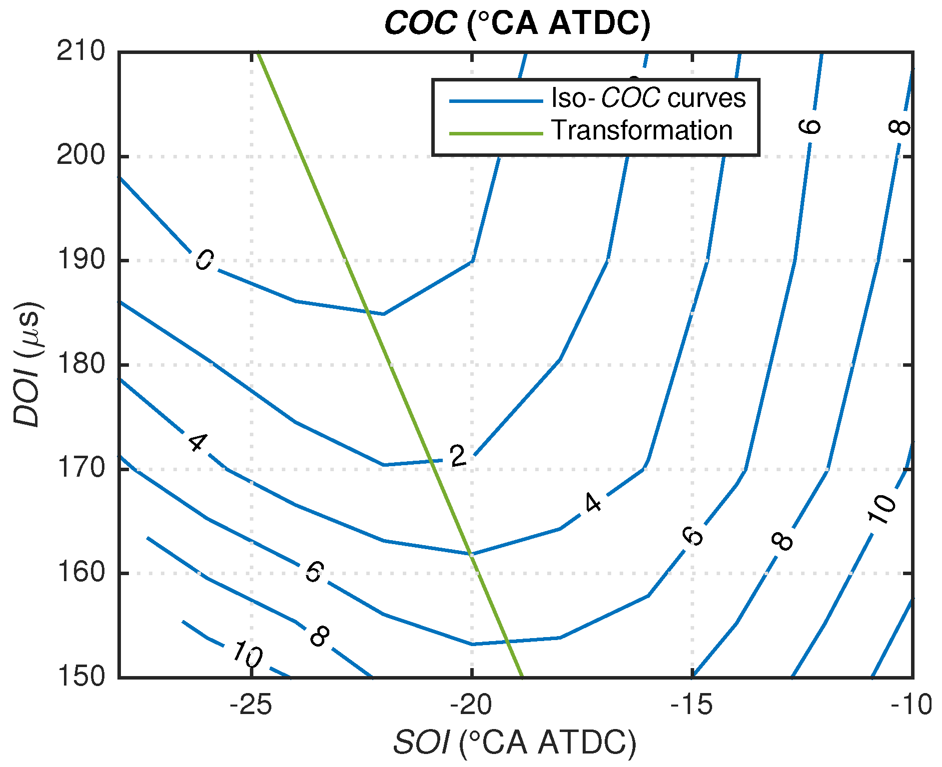
The function given in Equation (12) used for the transformation may be well approximated by an affine function. Figure 5 shows the corresponding affine approximation of Equation (12) and the center of combustion as a function of the inputs and .
Figure 4.
SIMO control—the transformation method.
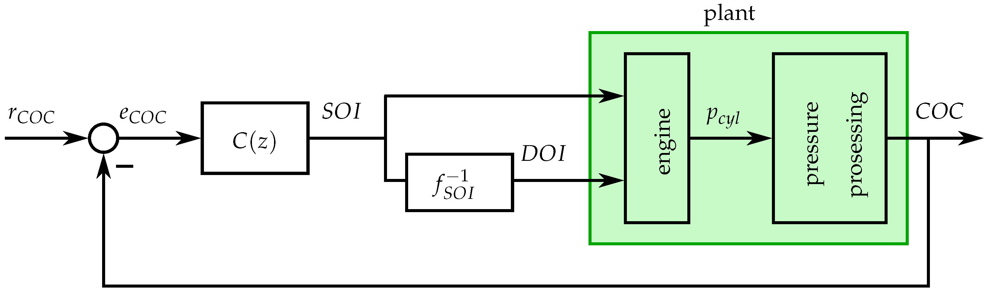
Controlling the center of combustion using the controller shown in Figure 4 solves the problem given by Equations (7) and (8) if the operating point is equal to the operating point used for the identification of the transformation. In other words, the amount of diesel used to maintain the center of combustion at any set value is minimal at the operating point used for the identification of the transformation.
Figure 5.
Measurements of the center of combustion depending on start and duration of injection and , respectively. The affine approximation of Equation (12) is shown as well.
For alternative operating points, the transformation may change. In order to identify such a transformation, exhaustive measurements are needed, where the inputs are varied over a reasonable region. Figure 6 shows the same operating point and the same transformation as those shown in Figure 5. Furthermore, the center of combustion is shown as a function of the inputs and for an alternative operating point. A similar range for the system output is shown. The conditions of the alternative operating point are given in Table 3. The results in Figure 6 clearly show that if the operating point conditions change and the combustion phasing must remain unchanged, the diesel injection has to be adjusted. At least the offset of the affine transformation has to be adapted for the alternative operating point. The method proposed in this paper can be used to identify the slope and the offset of the transformation.
Figure 6.
Measurements of the center of combustion depending on and for two different operating points. The operating point used for the identification (Table 2) is shown in blue, the corresponding transformation is shown in green, while the alternative operating point specified in Table 3 is shown in red.
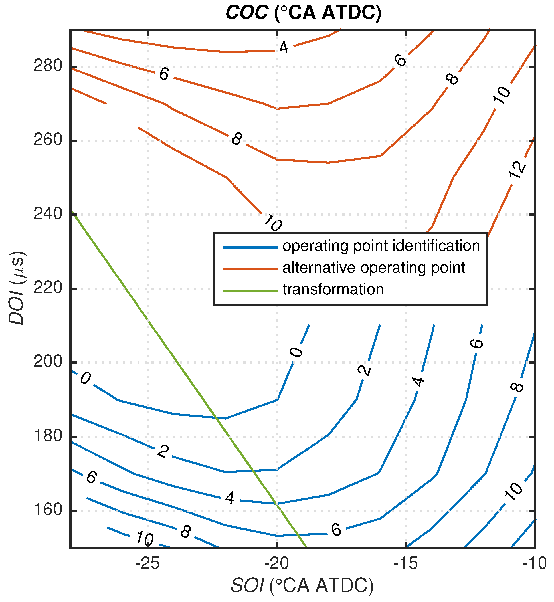
Table 3.
Alternative operating point.
2.3. MIMO
For the sake of completeness, a third method is introduced briefly that is not used in this paper. A transformation similar to the one presented in Section 2.2 is used to control the center of combustion . A second feedback controller is used in order to control the maximum pressure gradient of the combustion as well. The second controller shifts the transformation offset upwards, which leads to a higher amount of diesel used and therefore to a higher pressure gradient. By doing so, the maximum pressure gradient of the combustion can be manipulated while the center of combustion is kept at a constant value. Further details can be found in [18].
Analogously to the SIMO variant mentioned above, the slope of the transformation can be identified using the method proposed in this paper. The offset of the transformation at which the amount of diesel used is minimal is the saturation of the pressure gradient controller, which can also be identified using the proposed method.
3. Diesel-Minimal Combustion Control and Extremum Seeking
First, a short introduction to extremum seeking is given in Section 3.1, while the diesel-minimal combustion control method is presented in Section 3.2.
3.1. Introduction to Extremum Seeking
As early as 1951, extremum seeking was proposed for internal combustion engines [26]. Ever since then, extremum seeking has remained popular for internal combustion engines. A typical application is to vary the spark timing to maximize the power output of a spark ignition engine (see for example [26,27,28,29,30]). In addition, the optimal combustion phasing of homogenous-charge- compression-ignition (HCCI) and diesel engines can be found using extremum seeking, see [31,32], respectively. Multivariable extremum seeking used for the calibration of spark ignition engines can be found in [33,34]. The manipulated variables are spark advance, fuel/air ratio, and/or variable valve timings. Examples outside the field of internal combustion engines and an overview of the history of extremum seeking from 1922 to 2010 can be found in [35]. The authors of [35] revealed that extremum seeking gained popularity after stability was proven in [36].
Extremum seeking is a gradient-based optimization technique. The method is introduced for static functions. Further details about general extremum seeking can be found in [37], for example. Figure 7 shows the general structure of extremum seeking used to optimize a static function .
Figure 7.
General extremum seeking for a static function.
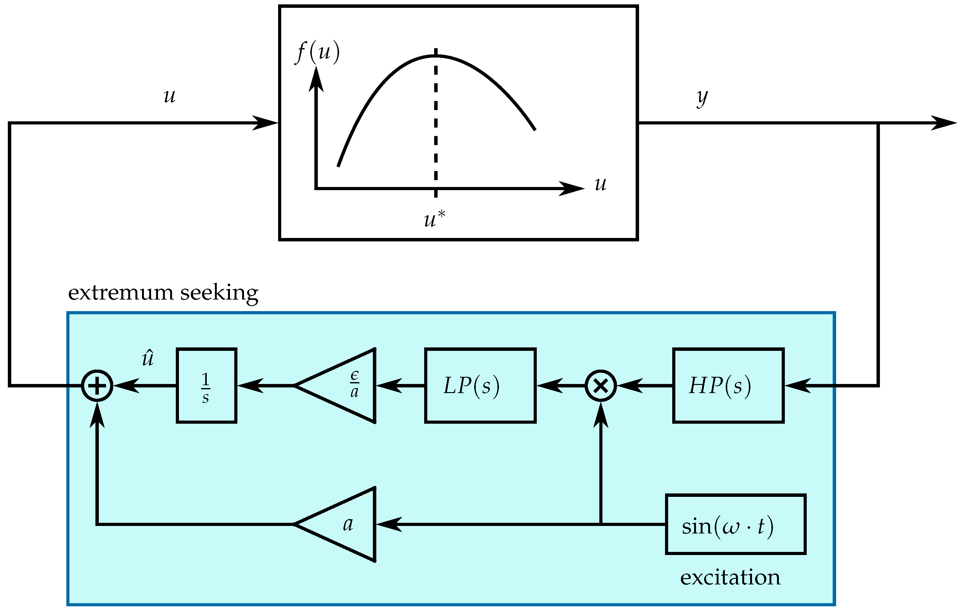
The input u consists of a DC component and a periodic excitation signal :
The output is a periodic signal, too. The high-pass filter removes the DC component of the periodic output y. The output of the high-pass filter is either in phase or opposite in phase with the excitation signal. The two signals are in phase if the local gradient is positive and opposite in phase if the local gradient is negative around the DC component . The product of the two signals has a DC component that is extracted by the low-pass filter , which is approximately proportional to the local gradient .
An integrator is used to drive the gradient to zero. The magnitude of the parameter ϵ and the low-pass filter determine how fast the gradient is driven to zero. The sign of ϵ is positive for a maximization problem and negative for a minimization problem.
3.2. Diesel-Minimal Combustion Control Using Extremum Seeking
Two similar concepts are presented in this paper. The general idea is first introduced using a rather intuitive approach, in the following referred to as “slow excitation approach”. A faster variant is then presented that facilitates the tuning and the necessary bandwidth separation, in the following referred to as the “fast excitation approach”. The slow excitation approach is introduced in order to show these facilitations and to motivate the fast excitation approach.
In both approaches, the controller presented in Section 2.1 is used in order to fulfill the equality constraint given by Equation (8). This controller manipulates the duration of injection to control the center of combustion . The plant is augmented by the dynamics of the feedback loop of the combustion controller. The dynamics have to be considered later in the design of the extremum seeking controller. The start of injection can now be manipulated in order to minimize the duration of injection .
This is basically a common concept to solve optimization problems with equality constraints, which is based on the elimination of equality constraints [38]. The elimination leads to an unconstrained optimization problem with fewer variables than in the original problem. As mentioned above, in this case, the remaining variable to minimize the amount of diesel used is the start of injection .
3.2.1. Slow Excitation Approach
Let be the duration of injection that solves the equality constraint given in Equation (8) as a function of the start of injection and the set value of the center of combustion :
The output of the function is the steady-state output of the feedback combustion controller, i.e., the duration of injection that the feedback combustion controller outputs as soon as the set value is reached. The minimization problem that remains after the elimination of the equality constraint is given as:
The necessary condition to solve the problem given in Equation (15) is:
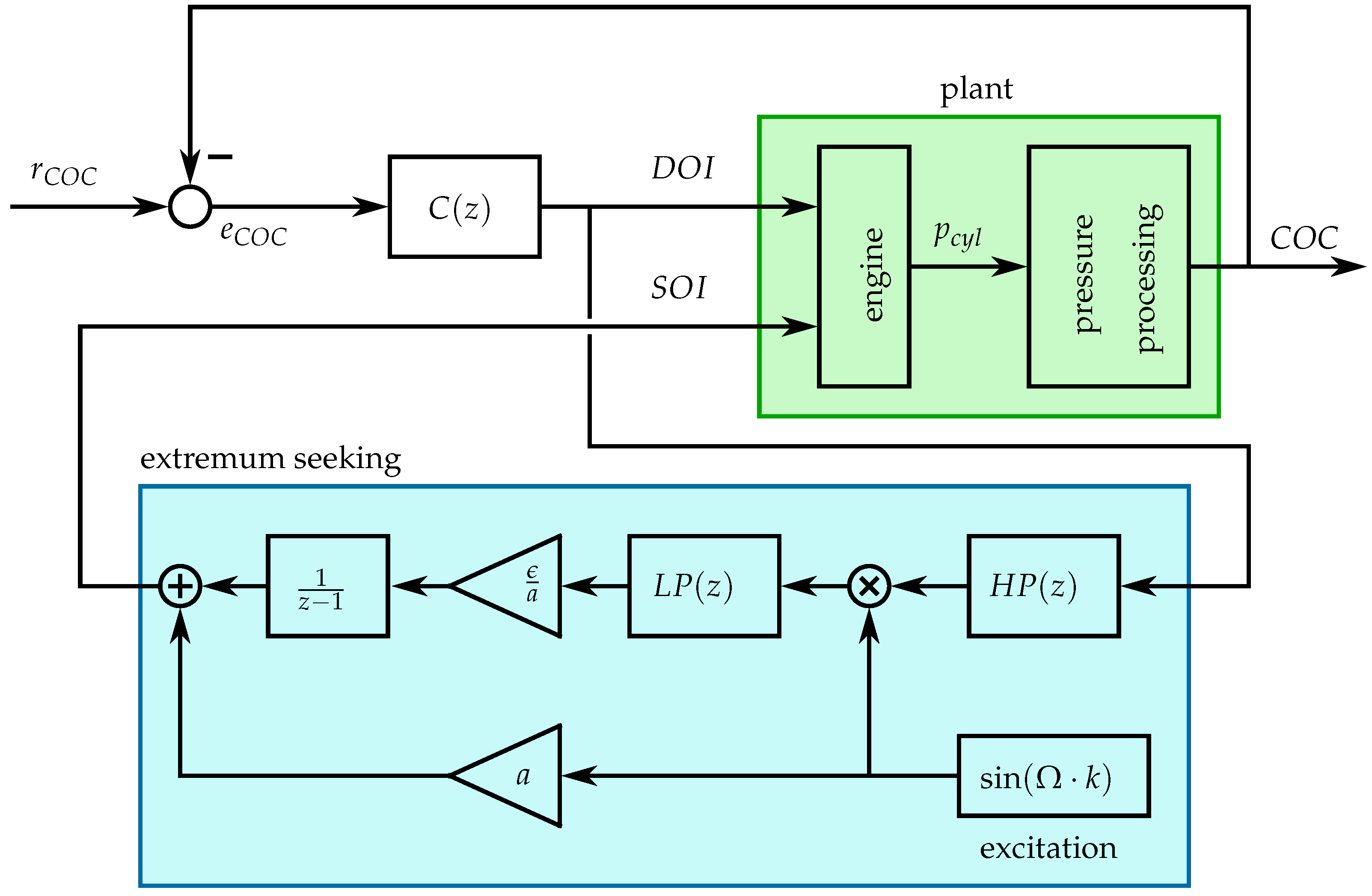
Figure 8 shows a possible structure that can be used to solve the problem given in Equation (15) using extremum seeking. A discretized version of the extremum seeking controller is used. The excitation signal has to be slower than the -stabilizing feedback loop. The behavior from to thus becomes an approximation of the function , i.e., the controller is able to compensate for the excitation signal such that the center of combustion proceeds along a curve of constant values of equal to . The extremum seeking controller thus drives the gradient to zero. The entire system is comparable to an extremum seeking controller applied to a static function (see Figure 7). This approach is intuitive, because the duration of injection that has to be minimized is fed to the extremum seeking block.
There are three different time scales that have to be considered if extremum seeking is applied to such a dynamic system ([36]):
- fast: dynamics of the system with -stabilizing feedback loop
- medium: excitation of the start of injection
- slow: integrator with adaptation rate ϵ and low-pass filter used to drive the gradient to zero, i.e., the extremum seeking.
Figure 8.
Diesel-minimal combustion control structure of the slow excitation approach: slow excitation on the start of injection . The duration of injection is fed to the extremum seeking controller.
The three time scales mentioned have to be chosen carefully in order to ensure convergence. In the following, an alternative structure is presented that changes the order of the time scales.
3.2.2. Fast Excitation Approach
First, the Lagrange multiplier theorem is applied to the constrained optimization problem given in Equations (7) and (8) that leads to the necessary conditions of optimality [39]. For an optimization problem with the objective function and the equality constraint , this theorem is given as:
Inserting Equations (7) and (8) leads to the following two necessary conditions of optimality:
The function describes the center of combustion as a function of the start and the duration of injection and , respectively (see Equation (1)). Equations (18) and (19) can thus be rewritten as:
The gradient is never zero (see Figure 5). This property is also required for the feedback controller used to stabilize the center of combustion (see Section 2.1). Therefore, in order to fulfill the necessary condition given in Equation (21), the optimal Lagrange multiplier that solves the optimization problem can not be zero either. This means that the gradient at the optimum has to be zero in order to fulfill the necessary condition given in Equation (20). Figure 9 shows the corresponding structure that uses extremum seeking to drive the gradient to zero.
Figure 9.
Diesel-minimal combustion control structure of the fast excitation approach: fast excitation on the start of injection . The center of combustion is fed to the extremum seeking controller.
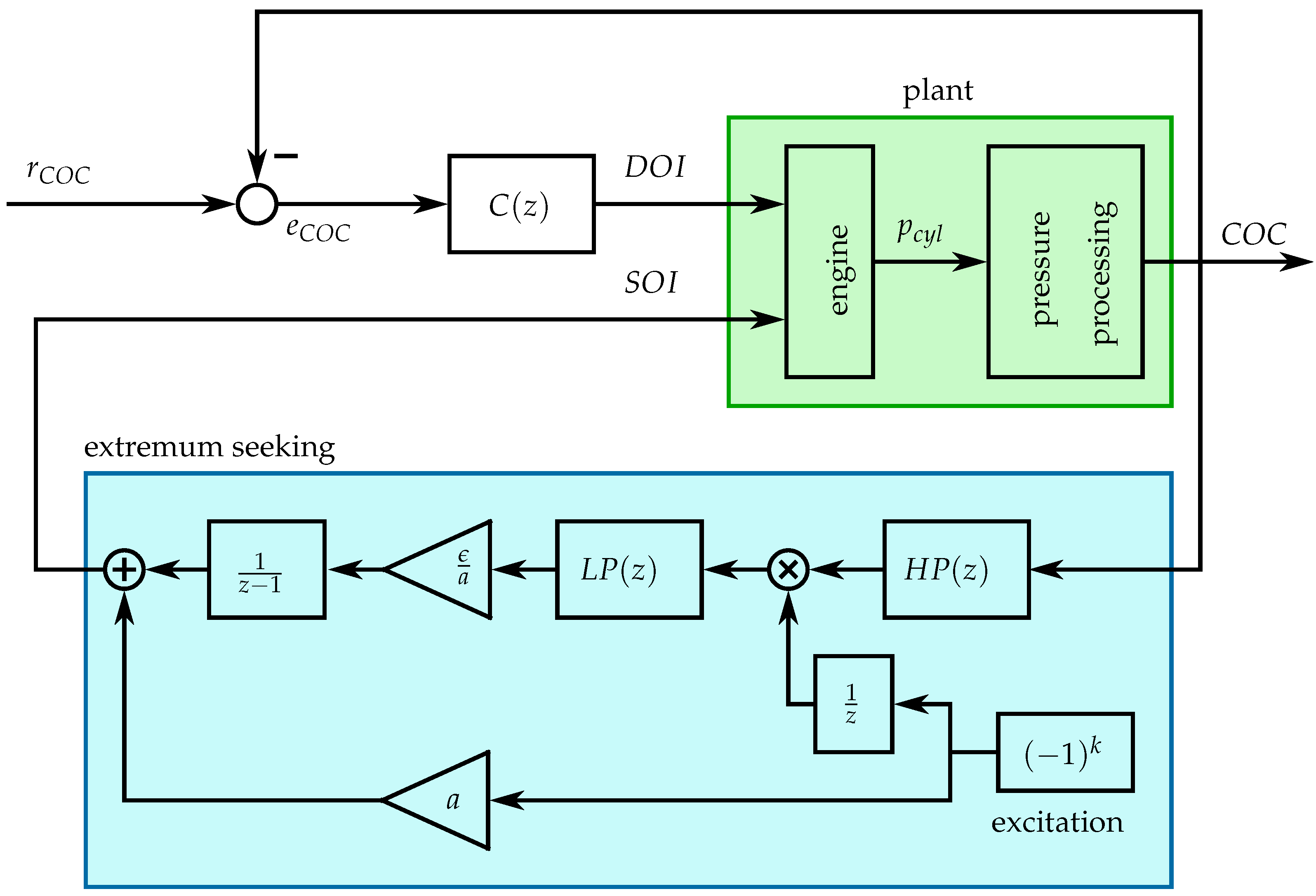
The time shift is added to the extremum seeking controller in order to assign the output to the corresponding input . The center of combustion at the time step k is a function of the inputs at the time step (see Equation (1)).
The excitation signal is chosen to be the fastest periodic signal possible for a given discrete system. The influence of the feedback controller used to stabilize the center of combustion is negligible at this frequency, such that the extremum seeking can approximate the gradient . Thus, a new order of time scales results:
- very fast: excitation of start of injection
- fast: dynamics of the system with -stabilizing feedback loop
- medium: integrator with adaptation rate ϵ and low-pass filter used to drive the gradient to zero, i.e., the extremum seeking.
The -stabilizing feedback loop is still described as “fast” since the bandwidths of the -stabilizing feedback controllers are the same in both approaches (Figure 8 and Figure 9). In the case of the fast excitation approach, the time scale of the extremum seeking follows directly.
Table 4 shows a comparison of the time scales of the two approaches. The extremum seeking of the fast excitation approach can be tuned faster than with the slow excitation approach. The reason is that for the slow excitation approach, the time scale of the excitation lies between the time scales of the extremum seeking and the feedback loop. This fact has to be considered during the tuning in order to ensure a proper time scale separation. In the case of the fast excitation approach, there is no need to consider the time scale of the excitation during the tuning. This facilitates the tuning of the various parameters.
Table 4.
Time scales of the two approaches.
4. Experimental Results
The fast excitation approach, as proposed in this paper and which is shown in Figure 9, is validated experimentally. The extremum seeking method is compared to the transformation method introduced in Section 2.2.
4.1. Validation of the Method
The chosen low-pass filter has the following form:
while the chosen high-pass filter has the following form:
The parameter of the low-pass filter is chosen such that the amplitude at the excitation frequency is . The parameter ϵ used to control the convergence rate is chosen such that the discrete-time integrator and the parameter ϵ together have the same bandwidth as the low-pass filter .
The parameter of the high-pass filter is chosen to be equal to . The high-pass filter has the goal to remove the DC component of the output signal . With the parameter chosen, the high-pass filter has a gain of about at the excitation frequency.
The minimal duration of injection is calculated offline using the data obtained from the identification measurements shown in Figure 3 (at the operating point given in Table 2). The offline optimum serves as the benchmark for the results of the proposed method.
Figure 10 shows two different experiments, where the start of injection is initialized at −29 °CA and at −11 °CA , respectively. In the first plot of Figure 10, the black line shows the reference value for the center of combustion . In the second plot, the black dashed line shows the optimal duration of injection calculated offline. The extremum seeking is activated at a time equal to zero. In both cases, the extremum seeking is able to approach the offline optimum, while the feedback controller keeps the center of combustion at its set value , which means that the problem given in Equations (7) and (8) is solved online.
The fast excitation of the start of injection leads to fast changes of the center of combustion that show a trend to be parallel to the curves of constant duration of injection , especially when being away from the optimum. This means that the signal contains the information of the gradient and that the extremum seeking can drive the gradient to zero.
Figure 10.
Two experimental results of the proposed extremum seeking method, i.e., the fast excitation approach shown in Figure 9, at a constant operating point (see Table 2). The start of injection is once initialized at −29 °CA and once at −11 °CA . The start of injection is shown without the excitation signal.
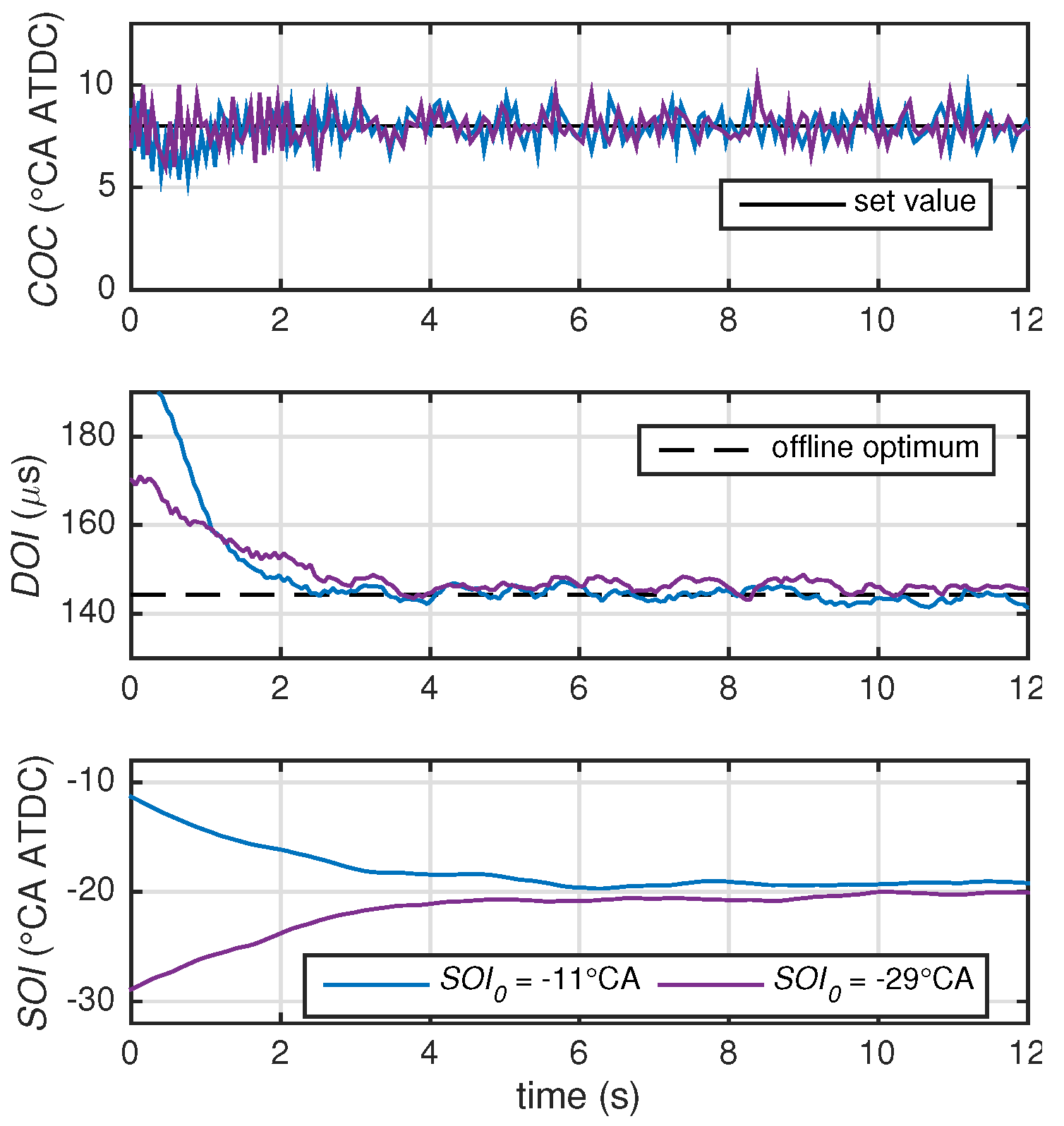
Figure 11 shows the discrete Fourier transforms (DFT) of the two experiments shown in Figure 10. The first plot shows the discrete Fourier transform of the experiment shown in Figure 10 that was initialized at = −11 °CA , while the second plot shows the discrete Fourier transform of the experiment that was initialized at = −29 °CA . For each experiment, two discrete Fourier transforms are carried out, one at the initialization point (before time equal to zero when referring to Figure 10) and one after convergence (after time equal to 10 s when referring to Figure 10). The excitation frequency of the extremum seeking amounts to one-half of the sampling frequency. The magnitude of the signal at the excitation frequency is highlighted with a circle for the initialization point, i.e., away from the optimum. An asterisk is used to highlight the magnitude after convergence for the same frequency.
Figure 11.
Magnitude plots of the discrete Fourier transforms (DFT) of the signals before and after convergence.
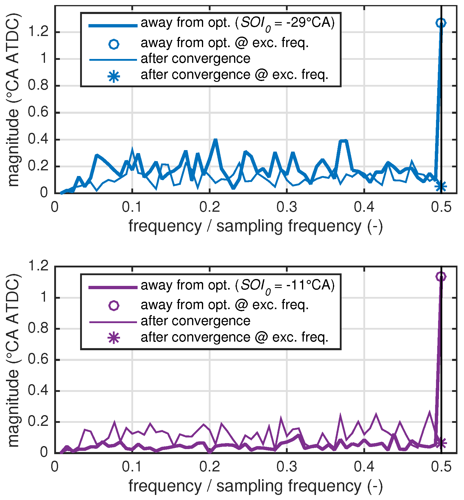
The magnitude at the excitation signal is dominant if the start of injection is away from the optimum. This is no longer the case after convergence, where the magnitude at the excitation frequency is in the same order of magnitude as the other frequencies. As soon as the optimum is reached, the excitation does not influence the output anymore, which means that the gradient is zero and the extremum seeking has converged.
Figure 12 shows a comparison of the fast excitation and the slow excitation approaches. For the slow excitation approach, the excitation frequency has to be chosen such that the feedback controller is able to compensate for the excitation signal, and the center of combustion proceeds along a curve of constant values equal to the set value . The excitation signal is a disturbance to the feedback control loop. The excitation frequency for the slow excitation approach is chosen such that the gain of the sensitivity at the excitation frequency is . The sensitivity is the transfer function from a disturbance to the plant output of a closed-loop system. The sensitivity is given as:
Figure 12.
Comparison of the fast excitation and the slow excitation approaches. The start of injection is initialized at −29 °CA . The start of injection is shown without the excitation signal.
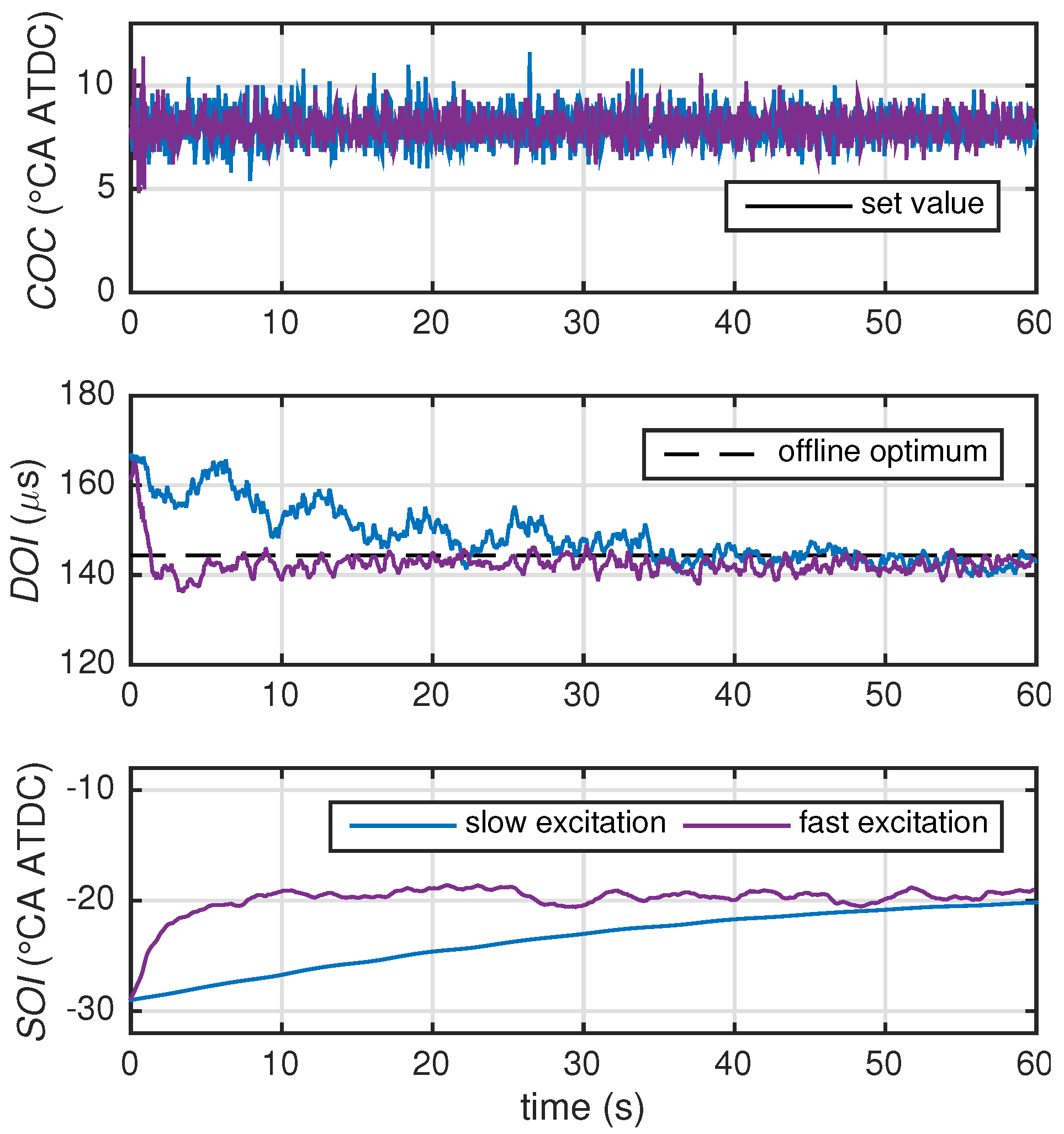
The parameters of the low-pass filter , the high-pass filter , as well as the convergence rate ϵ are chosen analogously to the fast excitation approach in order to allow a fair comparison. For an analogous tuning with respect to the excitation frequencies, the fast excitation approach is able to reach the optimum in a shorter time period. The fact that the fast excitation approach converges faster than the slow excitation approach is due to the different orders of time scales (see Table 4).
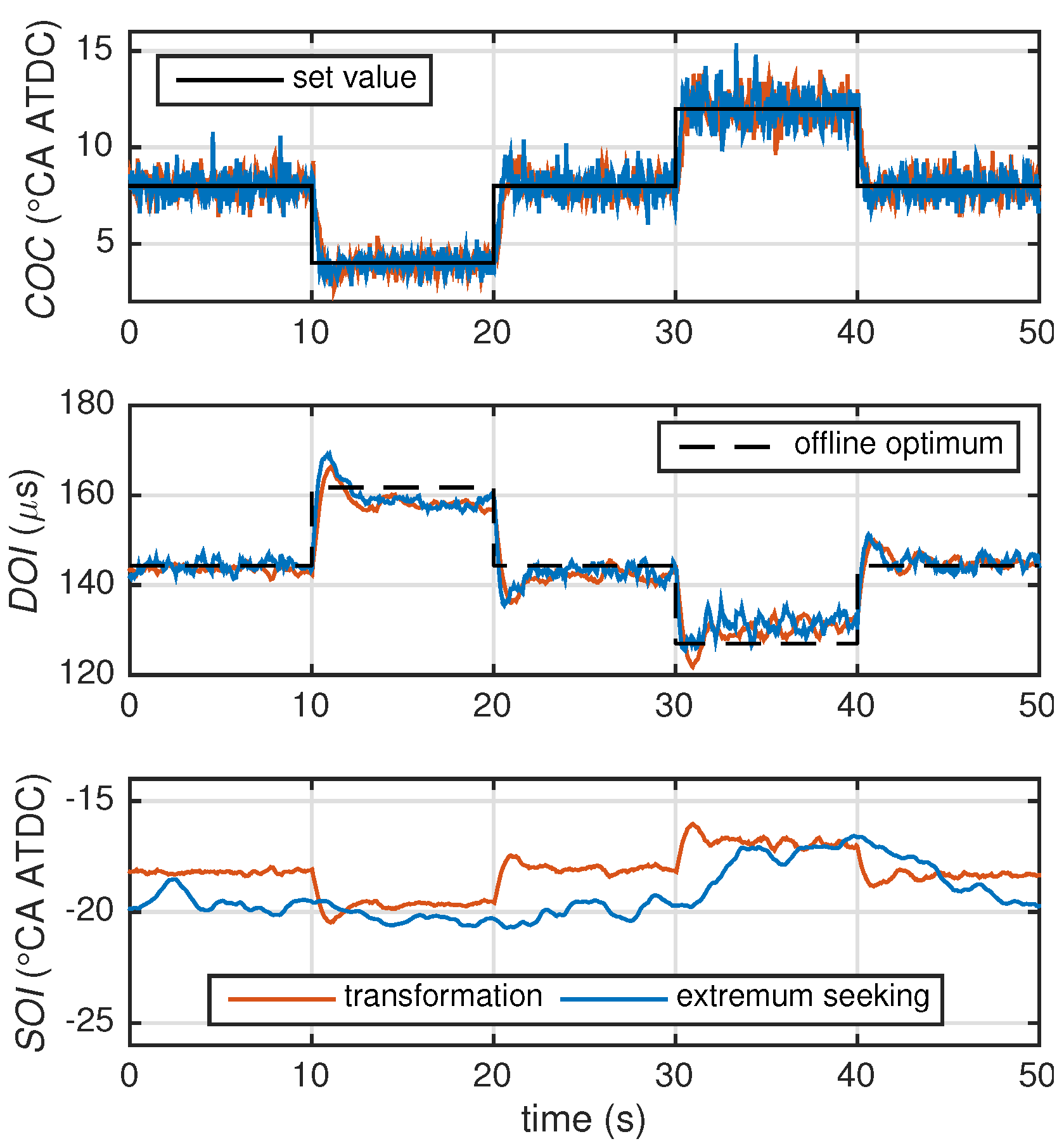
Figure 13 shows a comparison between the transformation method described in Section 2.2 and the proposed extremum seeking method at the operating point listed in Table 2. The set value for the center of combustion is stepwise changed between 4 °CA, 8 °CA and 12 °CA. The performances of the transformation variant and the proposed extremum seeking approach regarding the changes of are comparable because of their similar tuning. The extremum seeking does not influence the feedback control of the center of combustion since the bandwidths of feedback loop and extremum seeking are properly separated (see Section 3.2). The extremum seeking slightly changes the start of injection towards the identified values of the transformation method. The durations of injection of the two variants are comparable for small changes in . The start of injection is varied within 3 °CA, which has an almost negligible effect on the resulting . The major change in is due to the change in .
Figure 13.
Comparison of the transformation method and the fast excitation approach based on extremum seeking presented in this paper. The operating point evaluated is identical to the one used in the identification. The set value for the center of combustion is varied. For the extremum seeking approach, the start of injection is shown without the excitation signal.
4.2. Comparison at the Alternative Operating Point
In this section, the transformation method and the proposed extremum seeking method are compared at the alternative operating point listed in Table 3. With respect to the center of combustion , this operating point differs from the one used to identify the transformation (see Figure 6). At the alternative operating point, the transformation is thus not able to minimize the amount of diesel used.
Figure 14 shows that the extremum seeking approach can reduce the duration of injection and, therefore, the amount of diesel used. The extremum seeking approach is initialized at the start of injection of the transformation variant and is activated at time equal to zero.
Table 5 summarizes the results of the two variants. In the case of the extremum seeking approach, the measurements are carried out after convergence. Three measurements are carried out for each method. For each measurement, the results are averaged over 60 s.
Table 5.
Consumption comparison at alternative operating point. The subscripts and superscripts show the intervals of the measurements.
Figure 14.
Comparison of the transformation method and the fast excitation approach based on extremum seeking presented in this paper. The alternative operating point given in Table 3 is used, i.e., the operating point other than the one used for the identification of the transformation. For the extremum seeking approach, the start of injection is shown without the excitation signal.
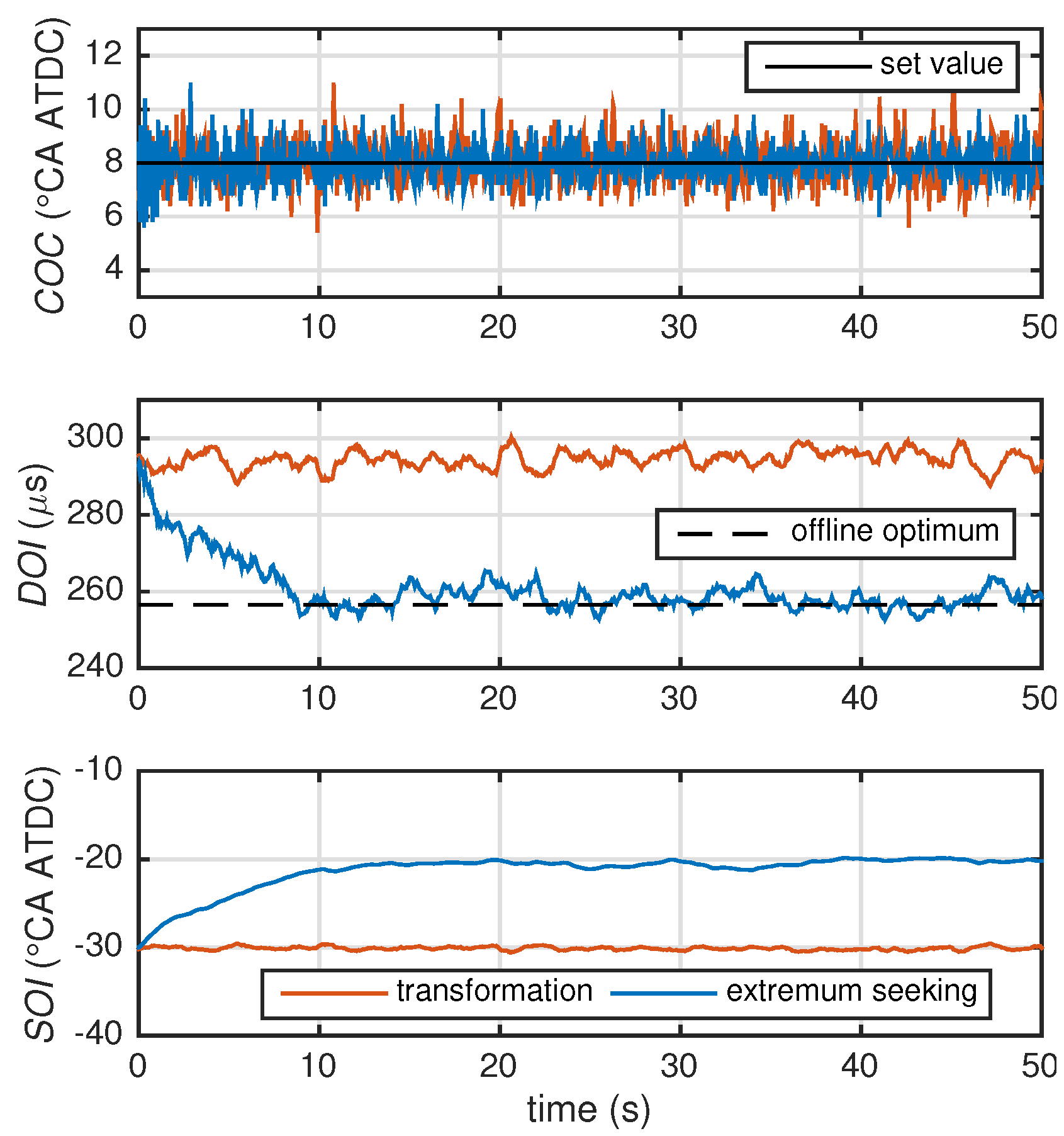
Table 5 shows the brake mean effective pressure , the natural gas mass flow , the diesel mass flow , the break-specific emissions, and the energetic diesel ratio defined as:
where is the mass of diesel and is the mass of natural gas consumed during the 60 s of measurement. The parameters and are the lower heating values of diesel and methane, respectively. Pure methane is used for the consumption measurements. For this specific example, the amount of diesel used can be reduced by more than 27% compared to the transformation variant, while the emissions are reduced by 4.9%.
5. Conclusions
This paper investigates the combustion control of natural gas-diesel engines. In such an engine, the directly injected diesel as the secondary fuel is only used to ignite the mixture of natural gas and fresh air. Natural gas is used as the primary fuel because of the low energy-specific emissions of methane, which is the main component of natural gas, and because of the availability of natural gas. These advantages of natural gas motivate the use of the least possible amount of diesel fuel. Furthermore, the size of the diesel tank can be reduced, or refilling of the diesel is needed less frequently.
A method is proposed in this paper that is able to maintain the center of combustion as an indicator of the combustion phasing at a demanded set value, while the amount of diesel used is minimized at the same time. A combination of feedback control and extremum seeking is used for that purpose. Simultaneously controlling the center of combustion and minimizing the amount of diesel used is possible, because the center of combustion can be manipulated by two degrees of freedom, namely the start and the duration of the diesel injection.
An experimental validation is presented that was run on a production-type 2.0 l, four-cylinder common-rail diesel engine converted to a natural gas-diesel dual-fuel mode. The amount of diesel used when applying the proposed method converges to the minimum. An offline estimation of the optimum based on exhaustive identification measurements is used as a benchmark. The performance of the feedback controller of the center of combustion is shown to not be influenced by the extremum seeking controller.
The method presented can be used to minimize the diesel consumption online, which is advantageous in the case of system changes such as injector aging, varying fuel qualities, or varying ambient conditions. Furthermore, it can be used to reduce engine calibration time. The effect of operating a dual fuel engine at minimum diesel condition on emission or combustion efficiency is subject to further investigations.
Acknowledgments
The project has been funded by the Swiss Federal Office of Energy (BFE).
Author Contributions
All authors have contributed significantly to this work.
Conflicts of Interest
The authors declare no conflict of interest.
References
- IEA Publications, International Energy Agency. CO2 Emissions from Fuel Combustion—Highlights; IEA Publications, International Energy Agency: Paris, France, 2012. [Google Scholar]
- IEA Publications, International Energy Agency. World Energy Outlook; IEA Publications, International Energy Agency: Paris, France, 2011. [Google Scholar]
- Bakar, R.A. A technical review of compressed natural gas as an alternative fuel for internal combustion engines. Am. J. Eng. Appl. Sci. 2008, 1, 302–311. [Google Scholar]
- Serrano, D.; Bertrand, L. Exploring the Potential of Dual Fuel Diesel-CNG Combustion for Passenger Car Engine. In Proceedings of the FISITA 2012 World Automotive Congress; Springer: Berlin/Heidelberg, Germany, 2013; pp. 139–153. [Google Scholar]
- Ott, T.; Onder, C.; Guzzella, L. Hybrid-Electric Vehicle with Natural Gas-Diesel Engine. Energies 2013, 6, 3571–3592. [Google Scholar] [CrossRef]
- Selim, M.Y. Pressure-time characteristics in diesel engine fueled with natural gas. Renew. Energy 2001, 22, 473–489. [Google Scholar] [CrossRef]
- Sahoo, B.; Sahoo, N.; Saha, U. Effect of engine parameters and type of gaseous fuel on the performance of dual-fuel gas diesel engines—A critical review. Renew. Sustain. Energy Rev. 2009, 13, 1151–1184. [Google Scholar] [CrossRef]
- Papagiannakis, R.; Rakopoulos, C.; Hountalas, D.; Rakopoulos, D. Emission characteristics of high speed, dual fuel, compression ignition engine operating in a wide range of natural gas/diesel fuel proportions. Fuel 2010, 89, 1397–1406. [Google Scholar] [CrossRef]
- Königsson, F.; Stalhammar, P.; Angstrom, H.E. Characterization and Potential of Dual Fuel Combustion in a Modern Diesel Engine; SAE Technical Paper 2011-01-2223; SAE International: Warrendale, PA, USA, 2011. [Google Scholar]
- Ishiyama, T.; Kang, J.; Ozawa, Y.; Sako, T. Improvement of Performance and Reduction of Exhaust Emissions by Pilot-Fuel-Injection Control in a Lean-Burning Natural-Gas Dual-Fuel Engine; SAE Technical Paper 2011-01-1963; SAE International: Warrendale, PA, USA, 2011. [Google Scholar]
- Guzzella, L.; Onder, C. Introduction to Modeling and Control of Internal Combustion Engine Systems, 2nd ed.; Springer-Verlag: Berlin/Heidelberg, Germany, 2010. [Google Scholar]
- Eriksson, L.; Nielsen, L. Modeling and Control of Engines and Drivelines; John Wiley & Sons: Chichester, UK, 2014. [Google Scholar]
- Kiencke, U.; Nielsen, L. Automotive Control Systems: For Engine, Driveline, and Vehicle, 2nd ed.; Springer-Verlag: Berlin/Heidelberg, Germany, 2005. [Google Scholar]
- Isermann, R. Engine Modeling and Control; Springer-Verlag: Berlin/Heidelberg, Germany, 2014. [Google Scholar]
- Eichmeier, J.; Wagner, U.; Spicher, U. Controlling gasoline low temperature combustion by diesel micro pilot injection. J. Eng. Gas Turbines Power 2012, 134, 072802. [Google Scholar] [CrossRef]
- Han, X.; Zheng, M.; Tjong, J. Clean combustion enabling with ethanol on a dual-fuel compression ignition engine. Int. J. Engine Res. 2015, 16, 639–651. [Google Scholar] [CrossRef]
- Ott, T.; Zurbriggen, F.; Onder, C.; Guzzella, L. Cylinder Individual Feedback Control of Combustion in a Dual Fuel Engine. Adv. Automot. Control 2013, 7, 600–605. [Google Scholar]
- Ott, T.M. Hybrid-Electric Vehicle with Natural Gas-Diesel Engine. Ph.D. Thesis, ETH Zurich, Zurich, Swizerland, 2013. [Google Scholar]
- Bargende, M. Schwerpunkt-Kriterium und automatische Klingelerkennung. MTZ Motortech. Z. 1995, 56, 623. [Google Scholar]
- Pischinger, R.; Kell, M.; Sams, T. Thermodynamik der Verbrennungskraftmaschine, 3rd ed.; Springer: Bonn, Germany, 2009. [Google Scholar]
- Zurbriggen, F.; Ott, T.; Onder, C.; Guzzella, L. Optimal Control of the Heat Release Rate of an Internal Combustion Engine with Pressure Gradient, Maximum Pressure, and Knock Constraints. J. Dyn. Syst. Meas. Control 2014, 136, 061006. [Google Scholar] [CrossRef]
- Emiliano, P. Spark ignition feedback control by means of combustion phase indicators on steady and transient operation. J. Dyn. Syst. Meas. Control 2014, 136, 051021. [Google Scholar] [CrossRef]
- Asad, U.; Zheng, M. Diesel pressure departure ratio algorithm for combustion feedback and control. Int. J. Engine Res. 2014, 15, 101–111. [Google Scholar] [CrossRef]
- Yang, F.; Wang, J.; Gao, G.; Ouyang, M. In-cycle diesel low temperature combustion control based on SOC detection. Appl. Energy 2014, 136, 77–88. [Google Scholar] [CrossRef]
- Borgers, M.; Haußner, M.; Houben, H.; Pechhold, F. Drucksensor-Glühkerze für Dieselmotoren. MTZ Motortech. Z. 2004, 65, 888–895. [Google Scholar] [CrossRef]
- Draper, C.S.; Li, Y.T. Principles of Optimalizing Control Systems and an Application to the iNternal Combustion Engine; American Society of Mechanical Engineers: New York, NY, USA, 1951. [Google Scholar]
- Scotson, P.G.; Wellstead, P.E. Self-tuning optimization of spark ignition automotive engines. IEEE Control Syst. Mag. 1990, 10, 94–101. [Google Scholar] [CrossRef]
- Larsson, S.; Andersson, I. Self-optimising control of an SI-engine using a torque sensor. Control Eng. Pract. 2008, 16, 505–514. [Google Scholar] [CrossRef]
- Mohammadi, A.; Manzie, C.; Nešić, D. Online optimization of spark advance in alternative fueled engines using extremum seeking control. Control Engineering Practice 2014, 29, 201–211. [Google Scholar] [CrossRef]
- Hellstrom, E.; Lee, D.; Jiang, L.; Stefanopoulou, A.G.; Yilmaz, H. On-Board Calibration of Spark Timing by Extremum Seeking for Flex-Fuel Engines. IEEE Trans. Control Syst. Technol. 2013, 21, 2273–2279. [Google Scholar] [CrossRef]
- Killingsworth, N.J.; Aceves, S.M.; Flowers, D.L.; Espinosa-Loza, F.; Krstić, M. HCCI engine combustion-timing control: Optimizing gains and fuel consumption via extremum seeking. IEEE Trans. Control Syst. Technol. 2009, 17, 1350–1361. [Google Scholar] [CrossRef]
- Lewander, M.; Widd, A.; Johansson, B.; Tunestal, P. Steady state fuel consumption optimization through feedback control of estimated cylinder individual efficiency. In Proceedings of the American Control Conference (ACC), Montreal, QC, Canada, 27–29 June 2012; pp. 4210–4214.
- Popovic, D.; Jankovic, M.; Magner, S.; Teel, A.R. Extremum seeking methods for optimization of variable cam timing engine operation. IEEE Trans. Control Syst. Technol. 2006, 14, 398–407. [Google Scholar] [CrossRef]
- Corti, E.; Forte, C.; Cavina, N.; Mancini, G.; Ravaglioli, V. Automatic Combustion Control for Calibration Purposes in a GDI Turbocharged Engine; SAE Technical Paper 2014-01-1346; SAE International: Warrendale, PA, USA, 2014. [Google Scholar]
- Tan, Y.; Moase, W.; Manzie, C.; Nešić, D.; Mareels, I. Extremum seeking from 1922 to 2010. In Proceedings of the 2010 29th IEEE Chinese Control Conference (CCC), Beijing, China, 29–31 July 2010; Volume 29, pp. 14–26.
- Krstić, M.; Wang, H.H. Stability of extremum seeking feedback for general nonlinear dynamic systems. Automatica 2000, 36, 595–601. [Google Scholar] [CrossRef]
- Ariyur, K.B.; Krstić, M. Real-Time Optimization by Extremum-Seeking Control; John Wiley & Sons: Hoboken, NJ, USA, 2003. [Google Scholar]
- Boyd, S.; Vandenberghe, L. Convex Optimization; Cambridge University Press: New York, NY, USA, 2004. [Google Scholar]
- Bertsekas, D. Constrained Optimization and Lagrange Multiplier Methods; Athena Scientific: Belmont, MA, USA, 1996. [Google Scholar]
© 2016 by the authors; licensee MDPI, Basel, Switzerland. This article is an open access article distributed under the terms and conditions of the Creative Commons by Attribution (CC-BY) license (http://creativecommons.org/licenses/by/4.0/).