1. Introduction
Hybrid electric vehicles (HEVs) have attracted increasing attention owing to high demand for fuel-economy and environmentally friendly vehicles, which combine an internal combustion engine (ICE) and one or more electric motors [
1,
2,
3]. Depending on the drivetrain, power sources are provided in various configurations to improve fuel consumption, emission, and performance.
In general, permanent magnet (PM) brushless machines are preferred for automation applications, where high torque and energy efficiency are the most valuable attributes [
4,
5]. Among these, flux switching permanent magnet (FSPM) motors are gaining interest as competitive candidates for the next generation of hybrid drivetrain application, because of their simple and rugged construction, sinusoidal back-electromotive force (EMF), easy thermal management, compact size and high torque capability [
6,
7]. To further promote the reliability and torque density of the motor drive, a nine-phase FSPM (NP-FSPM) motor drive has been proposed for hybrid electric vehicles recently [
8,
9].
Multiphase FSPM motor is a promising form for reducing the amplitude of torque pulsation and increasing its frequency. Hence, four-, five-, six- and nine-phase FSPM motors have been successively studied in conjunction with different stator/rotor pole numbers in recent years. By employing increased winding redundancy compared to three phases, the stator winding of the multiphase FSPM motor can keep on forming the circular rotating magnetic field when a fault occurs in one or even more phases [
10]. The static performance of FSPM motors with phase numbers ranging from four to six are investigated in [
11], and it demonstrates that FSPM motors with high phase numbers offer significant benefits over three-phase topology in terms of torque density. In [
12], design considerations for FSPM motors with five-phase 10/18-pole and 10/19-pole for high reliability applications were presented, showing that they inherently offer improved fault-tolerance and reduced PM material. In [
8], three topologies of NP-FSPM for low-speed and fault-tolerant applications were developed, and a 36/34-pole NP-FSPM machine was chosen to achieve the negligible cogging torque. To prove the high fault-tolerance, two fault-tolerant control techniques, namely remedial brushless AC (BLAC) operation and remedial BLAC with harmonic current injection operation, are proposed for this machine [
13]. As a result, multiphase FSPM motors can be regarded as one potential power source for HEV drive systems.
However, the current research on multiphase FSPM motors has mainly focused on the structure, operating principles, and static torque performance. The main current control technique presented for FSPM motors in the literature is hysteresis control [
14,
15], which provides a fast and simple solution for multiphase FSPM motor drives, but it uses variable switching frequency that results in unbalanced operation. In addition, the vector space decomposition (VSD) method in multiphase induction motors (IM) and PM synchronous motors (PMSM) is a known conventional method [
16,
17,
18]. However, the operating principles and structure of FSPM motors are different from traditional IM and PMSM. For a multiphase FSPM motor, the PMs and armature windings are all located on the stator, while its rotor only consists of iron. Hence, the back-EMF and torque result from interaction between the motionless PM flux and rotor saliency, which differs from conventional multiphase PMSM [
19]. Hence, control of a multiphase FSPM motor is more challenging because of the low-order stator harmonic currents arising from motor parameter inaccuracies and non-ideal behavior of the inverter.
Considering the points mentioned above, an NP-FSPM motor drive system for use in HEVs is developed. The main focus of this paper is to develop the mathematical model in the dq reference frames and to implement fully decoupled current controls. Additionally, the controllability in post-fault operation is discussed. Both simulation and experiments are conducted to verify the low torque pulsation, high fault-tolerant capability and high dynamic performance of the drive system.
2. Motor Features
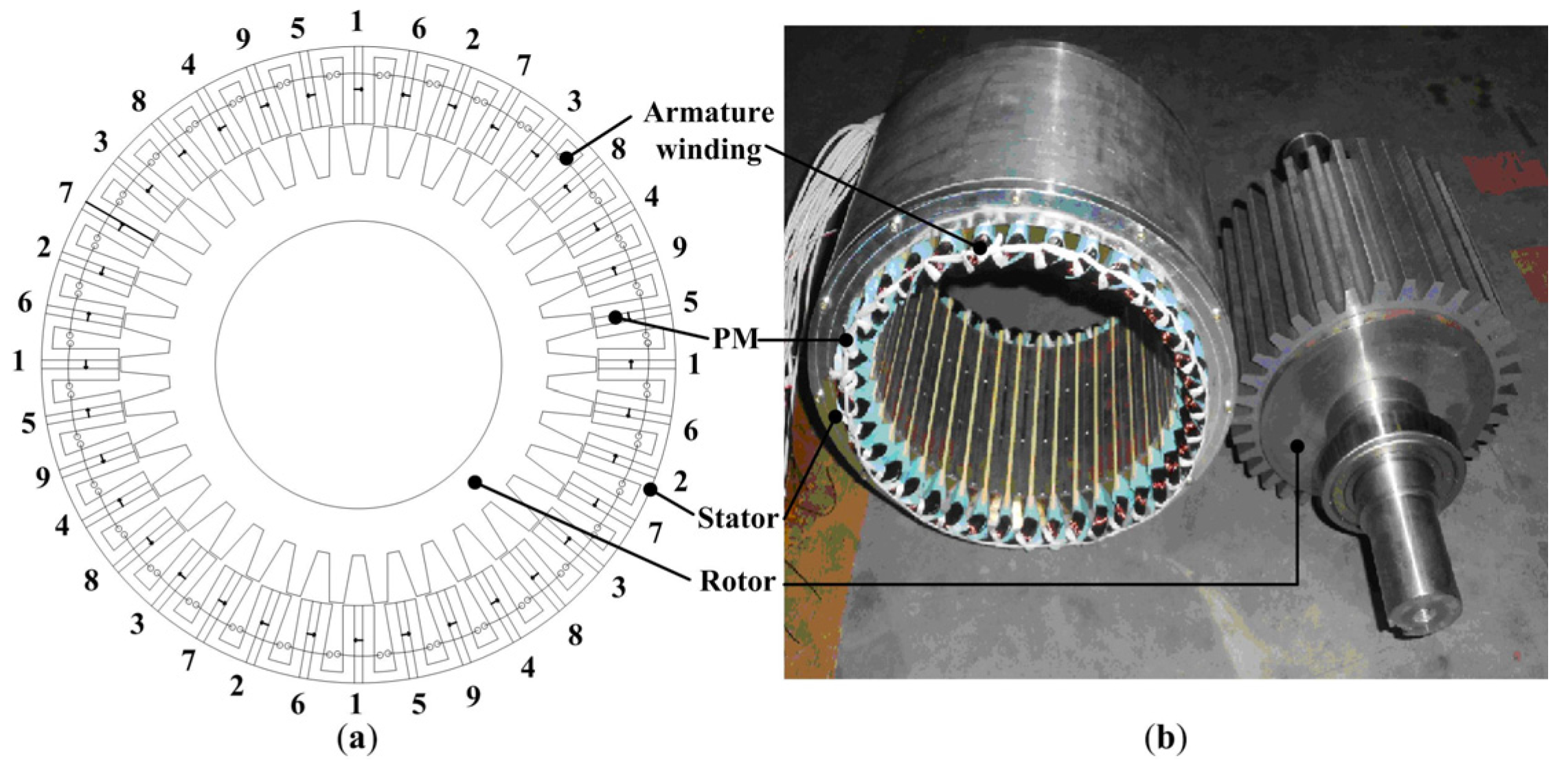
Figure 1 shows the arrangement of a 34-rotor-pole, 36-stator-pole winding distribution prototype for the NP-FSPM motor. There are four coils in each phase, e.g., four coils marked as “1” for phase 1, and each coil surrounding only one tooth. The adjacent phases are spatially displaced by 2π/9 rad. Thus, the resultant magneto-motive force (MMF) waveform will be established by nine equally spaced phase windings. The detailed specifications of the NP-FSPM motor are tabulated in
Table 1.
The NP-FSPM motor can provide a maximum torque of 220 N·m with a top speed of 500 rpm, meeting the demands of low-speed high-torque applications. Nevertheless, the NP-FSPM motor also suffers from narrow constant power speed range as in the traditional PMSMs, due to the constant magnet flux provided by stator PMs.
Figure 1.
36/34-pole NP-FSPM machine. (a) Cross section; (b) Prototype of stator and rotor.
Figure 1.
36/34-pole NP-FSPM machine. (a) Cross section; (b) Prototype of stator and rotor.
Nonlinear transient finite-element (FE) analysis is utilized to calculate the back electromotive force (EMF) and the cogging torque of the machine.
Table 1.
Key design parameters of the nine-phase flux-switching permanent-magnet (NP-FSPM) motor.
Table 1.
Key design parameters of the nine-phase flux-switching permanent-magnet (NP-FSPM) motor.
| Rated power | 10 kW | Rotor bore diameter | 120 mm |
| Rated speed | 500 rpm | Air gap length | 1 mm |
| Rated phase voltage | 230 V | Br of PMs | 1.2 T |
| Rated phase current | 4.83 A | Resistance per coil | 1.3 Ω |
| Stack length | 155 mm | Stator-PM magnetic flux | 0.224 Wb |
| Stator inner diameter | 260 mm | Shaft length | 180 mm |
| Stator outer diameter | 327 mm | Rotary inertia | 0.05 kg·m2 |
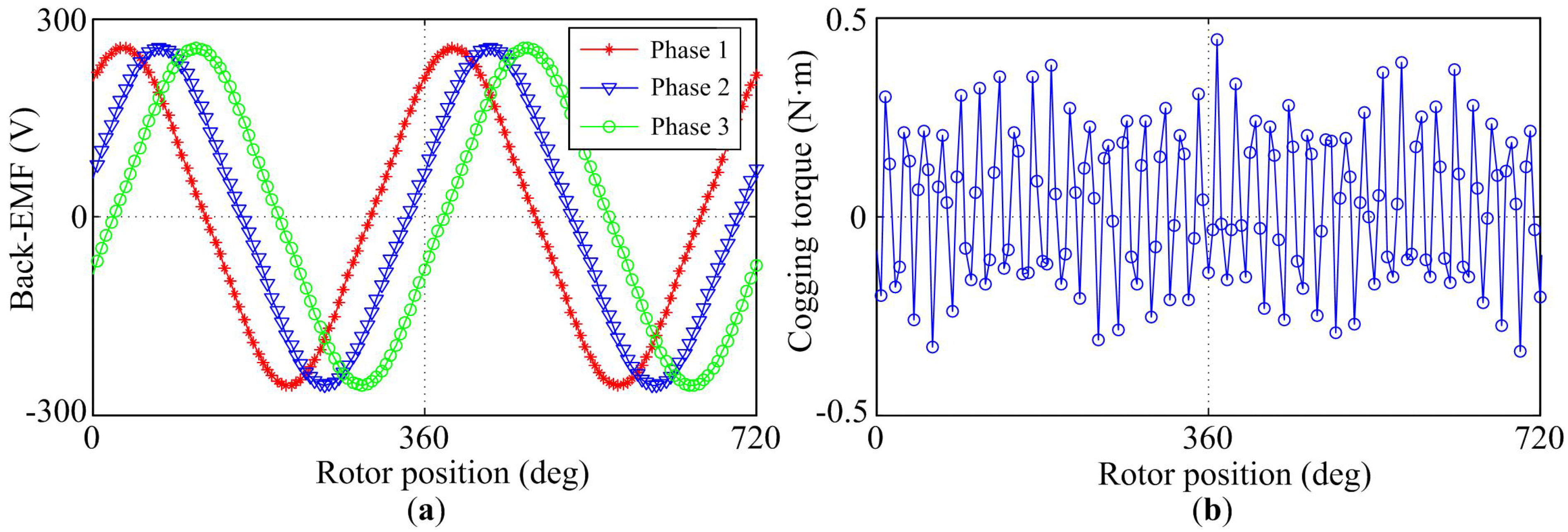
Figure 2a shows the back-EMF waveform of the machine at the rated speed of 500 rpm. As shown in the figure, the back-EMF waveform is sinusoidal. Thus, this kind of NP-FSPM motor can be driven as a brushless ac (BLAC) motor.
Unlike traditional PMSMs, the cogging torque of FSPM motors arises from the interaction between the stator-PMs and rotor slots where the stator winding is unexcited, which is shown in
Figure 2b. It can be seen that the peak value of cogging torque is less than 0.5 N·m, only 0.25% of the rated torque of the machine, due to the fact that the cogging torque decreases with increase in phase number and the frequency of the cogging torque increases with phase number and is proportional to the half of the stator pole number. Based on the FE analysis of the cogging torque, the low torque pulsation of the machine design is confirmed [
20].
Figure 2.
Static performance. (a) Back-EMF; (b) Cogging torque.
Figure 2.
Static performance. (a) Back-EMF; (b) Cogging torque.
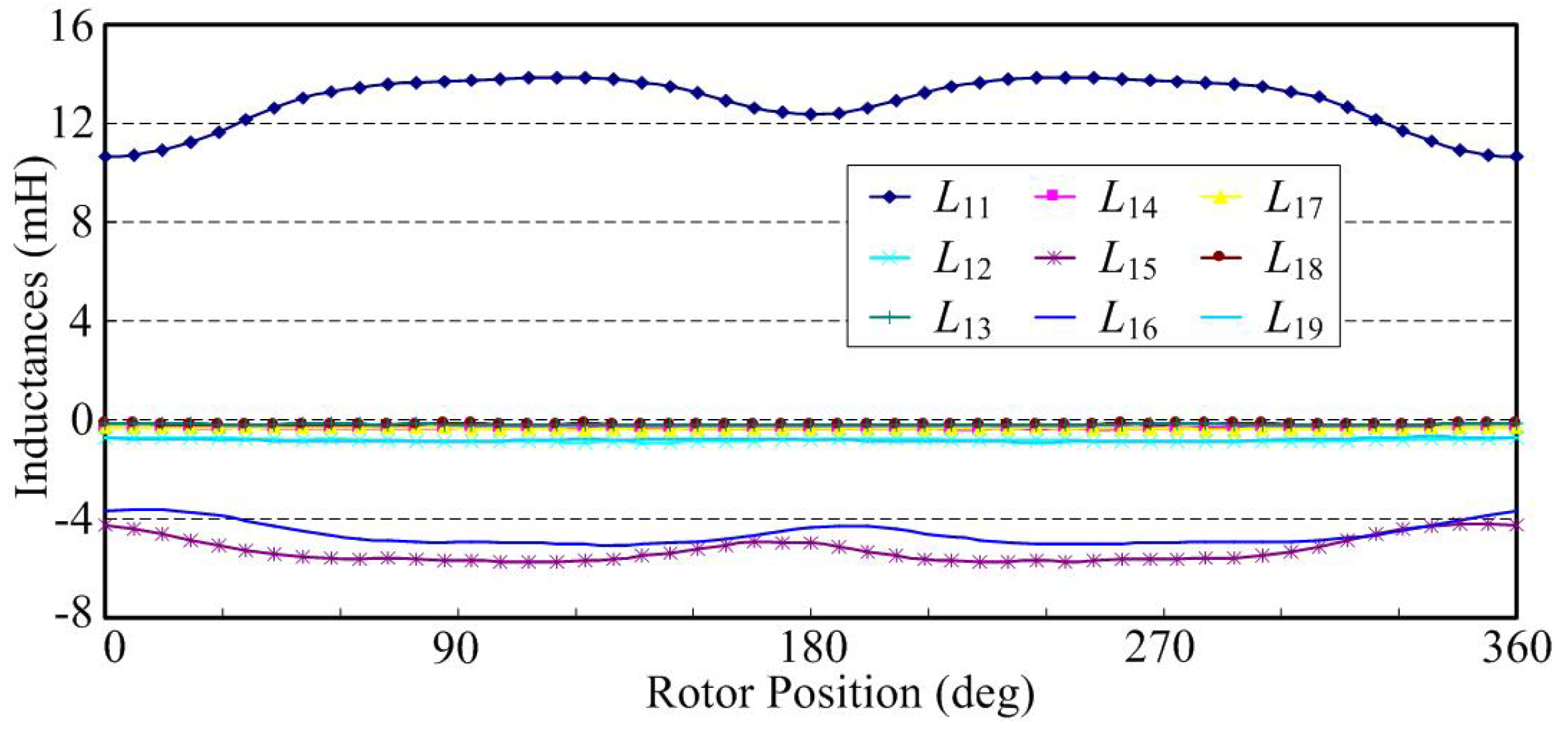
In some literature, the mutual inductance is ignored in the vector-controlled multiphase motor drive system, which could bring some defects to model accuracy in simulation. In this paper, the stator inductance profiles are also obtained from FE solutions of the NP-FSPM motor and stored in look-up tables of data that includes the rotor position dependence.
Figure 3 shows the self- and mutual inductances in phase 1.
Figure 3.
Self- and mutual inductances in phase 1.
Figure 3.
Self- and mutual inductances in phase 1.
3. Mathematical Modeling Based on VSD
To explore the control strategies for the NP-FSPM motor system, the machine mathematical model should adequately describe the dynamics of the drive system as simply as possible. In order to implement the VSD approach for a NP-FSPM motor, a minor modification should be firstly made in such a way that the
d-axis is chosen to be the rotor position and where the stator-PM flux-linkage of phase 1 is the maximum. As a result, the following transformation matrices are adopted:
where γ = 2π/9, and θ is the electrical rotor position. According to Kirchhoff’s current law, zero sequence currents cannot flow into a symmetric star-connection winding, hence are neglected in this paper. The rotational transformation matrix Equation (1) consists of the stationary frame transformation matrix
C and rotation matrix
D(θ).
According to the VSD theory for the NP-FSPM motor, through Equation (1), the phase-variable (current, voltage or flux linkage) are decoupled into four separate synchronous reference frames, which are called d1-q1 plane and dh-qh (h = 3, 5, 7) plane in this paper, yielding a simple solution to the description of the machine model.
In a perfectly symmetrical situation, with the rotational transformation matrix Equation (1), the fundamental component and the harmonics of the order of 18
k ± 1 (
k = 0, 1, 2, 3 …) are mapped into the
d1-
q1 plane, the harmonics of the order of 18
k ± 3 are mapped into the
d3-
q3 plane, the order of 18
k ± 5 are mapped into the
d5-
q5 plane, and the order of 18
k ± 7 are mapped into
d7-
q7 plane. Those harmonic components mapped in the
d1-
q1 plane contribute to the electromechanical energy conversion, while
dh-
qh (
h = 3, 5, 7) plane components do not generate electrical torque. As discussed in [
14], any imbalance in the stator windings or supply voltages causes the fundamental components and all the harmonics to appear in each reference frame in the multiphase induction motor, which also occurs in the multiphase FSPM motors. To verify the effectiveness of the controllability of harmonic components in the nine-phase system, the low-order harmonics, such as the third-, fifth-, and seventh- harmonic components, are considered in this paper, accompanied with the fundamental component.
Based on Equation (1), the stator voltage equations in the
d1-
q1 and
dh-
qh reference frames are:
where
Ld1 and
Lq1 are stator inductance in
d1-axis and
q1-axis respectively,
Ldh and
Lqh are stator inductance in
dh-
qh axis,
Rs is the phase resistance, ω is the rotor electrical angular velocity, and ψ
m is the flux linkage established by stator-PMs.
The electromagnetic torque can be derived from partial derivative of co-energy with respect to mechanical rotor position as:
where
p is the number of pole-pairs. The electromagnetic torque is composed of two parts. The first part is the PM torque, which arises from the interaction of the stator-PM flux and
q1-axis stator current component. The second part is the reluctance-torque component caused by inductance variation as a function of the rotor position.
4. Control Strategies of NP-FSPM Motor
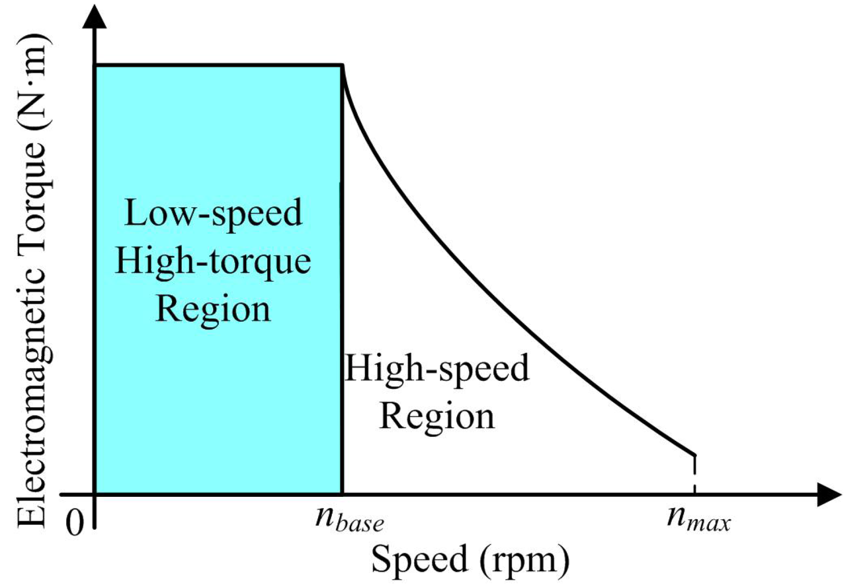
4.1. Torque-Speed Characteristic Analysis
As to traction of HEVs electric propulsion, high/smooth torque output in the low speed region and a wide speed range in the constant-power region are preferable, to achieve fast torque response and high-speed cruise performance [
2]. Therefore, multiphase FSPM motors used in HEVs need to exert a constant torque (CT) mode over the low-speed region and operate with field-weakening (FW) mode in the high speed region. The typical torque-speed characteristic is given by
Figure 4 [
3].
Figure 4.
Torque-speed characteristic of NP-FSPM.
Figure 4.
Torque-speed characteristic of NP-FSPM.
This paper mainly focuses on the control and performance of the NP-FSPM motor in the low-speed region.
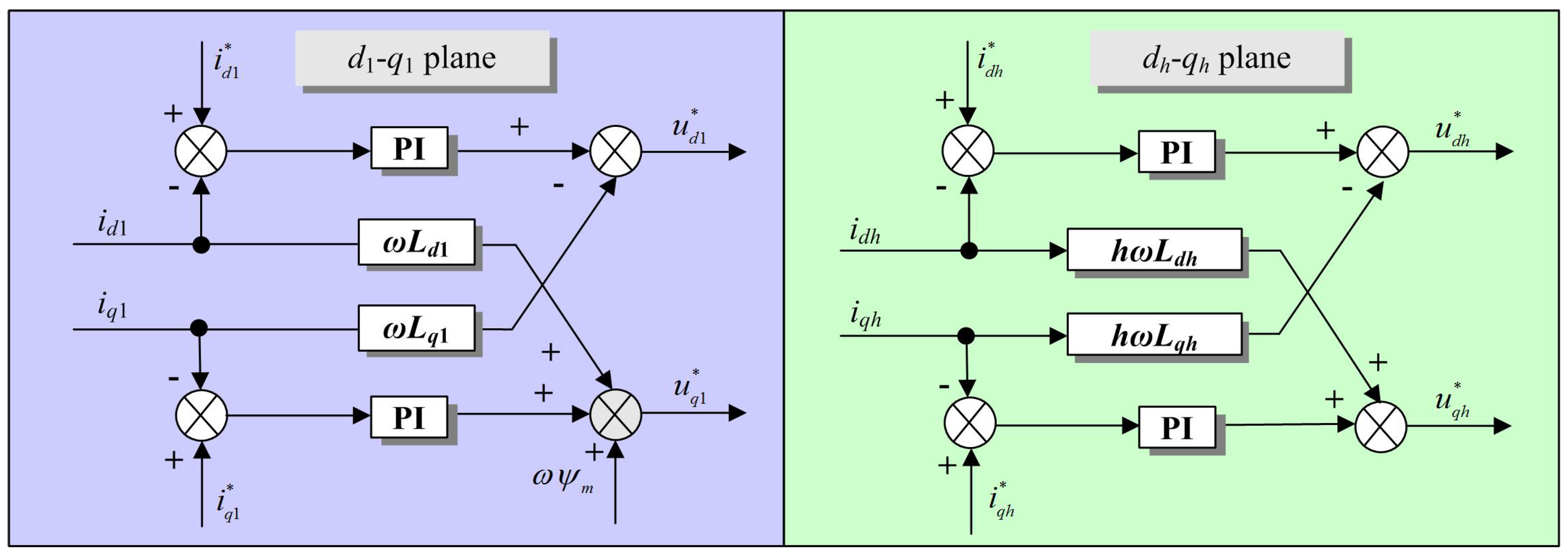
4.2. Fully-Decoupled Current Control during Normal Operation
In normal operations, the electric propulsion should perform with low torque pulsation and fast dynamic response. The majority of challenges in the NP-FSPM machine are related to the issues with currents applied to the motor. According to
Section 3, if VSD is applied to phase currents, the
d1-
q1 and
dh-
qh plane currents are directly controlled variables in the stator-flux-oriented scheme and consequently can be effectively manipulated. This feature provides a very effective way to solve current-related issues and strongly supports stator-flux-oriented control as the recommended control method for the NP-FSPM machine.
The control scheme is based on a conventional solution of synchronous current control using typical linear proportional and integral (PI) controllers.
Figure 5 presents the block diagram of the fully-decoupled control scheme. Four pairs of synchronous current controllers in conjunction with eight PIs are used to regulate both the
d1-
q1 plane currents and the
dh-
qh (
h = 3, 5, 7) plane currents. Since
dh-
qh is also a synchronous frame, any specific low-order harmonic (such as the third, the fifth and the seventh) currents which would appear as dc components of the
dh-
qh current controller through transformation
T(
θ) will be completely controlled. Consequently, to eliminate the unwanted low-order harmonic currents, the reference currents in the
dh-
qh plane should always be:
where “*” denotes the reference value.
Figure 5.
Fully-decoupled current control scheme.
Figure 5.
Fully-decoupled current control scheme.
In order to improve the dynamic performance in terms of PI controller based current control, the cross coupling effects between synchronous voltages should be cancelled out by feeding the following positive compensation:
On the basis of the mathematical model of the NP-FSPM motor, the decoupling system in the
d1-
q1 and
dh-
qh planes has the following simple transfer functions:
Due to the controllability of dh-qh plane currents, robust control voltage generation can be achieved in terms of Equations (7) and (8), even in the condition of low-order harmonic currents caused by motor parameter inaccuracies or nonlinear characteristics of the voltage source inverter (VSI). Hence, the significance of the accuracy of the NP-FSPM motor parameters in the fully-decoupled current control scheme appears not to be a major problem.
4.3. Reconstruction of Harmonic Current Components during Post-Fault Operation
Moreover, the electric propulsion should also exhibit high fault tolerance in the event of a fault condition. As the stator
d1-
q1 current components are required for the flux/torque control in the NP-FSPM motor, another three pairs of stator harmonic current components (the third, the fifth and the seventh), regarded as additional degree of freedom (ADF), can be effectively utilized for an appropriate post-fault operating strategy. It should be noted that the ADFs have been used to deal with open-circuit fault in multiphase machines for various specific aims, such as minimum loss or maximum torque output [
21,
22,
23]. However, there is no evidence that fault-tolerant controllability has ever been attempted before by dispensing with these additional degrees of freedom. Hence, possibilities for the implementation of a fault-tolerant operating strategy will be further elaborated.
In order to maintain the torque-producing current components
iα1 and
iβ1 during post-fault operation, namely, to keep the undisturbed MMF, for the case with open-circuit fault in phase 1, the following constrained optimization problem must be solved [
13]:
Based on the solution of stationary frame current components with minimum loss criteria Equation (9), implementation of a fault-tolerant control strategy can be further achieved in terms of seven kinds of harmonic current components reconstruction modes, which are listed in
Table 2, where Minor Reconstruction, Mid Reconstruction and Max Reconstruction, represent the amount of modification in the current controller. Taking the first Minor Reconstruction mode as an example, only the third harmonic current component
iα3 is reconstructed to be −
iα1 while the other harmonic current components are still kept to be zero.
Table 2.
Post-fault operation modes.
Table 2.
Post-fault operation modes.
| Minor Reconstruction | Mid Reconstruction | Max Reconstruction |
|---|
iα3 = −iα1
(iβ3 = iα5 = iβ5 = iα7 = iβ7 = 0)
or
iα5 = −iα1
(iα3 = iβ3 = iβ5 = iα7 = iβ7 = 0)
or
iα7 = −iα1
(iα3 = iβ3 = iα5 = iβ5 = iβ7 = 0) | iα3 = iα5 = −iα1/2
(iβ3 = iβ5 = iα7 = iβ7 = 0)
or
iα3 = iα7 = −iα1/2
(iβ3 = iα5 = iβ5 = iβ7 = 0)
or
iα5 = iα7 = −iα1/2
(iα3 = iβ3 = iβ5 = iβ7 = 0) | iα3 = iα5 = iα7 = −iα1/3
(iβ3 = iβ5 = iβ7 = 0) |
4.4. Carrier-Based Modulator
A well-defined switch frequency characteristic performed in the electric propulsion is also preferred. On the other hand, current harmonics caused by non-sinusoidal air gap flux can be reduced by intentionally feeding the right combination of supply harmonic voltages to the machine. In order to produce independent voltage vector in each d-q plane and ease the real-time implementation, an equivalent space vector pulse-width-modulation (SVPWM) modulator using max-min injection is adopted here.
First, by applying inverse
T(θ), the reference phase voltage phasor
Up is formed as:
where
Up = [
u1,
u2,
u3,
u4,
u5,
u6,
u7,
u8,
u9]
T,
Udq = [
ud1,
uq1,
ud3,
uq3,
ud5,
uq5,
ud7,
uq7]
T.
Then, phase voltage references with max-min injection are compared with a high-frequency carrier waveform (usually a triangular signal). The modulated signal can be given as:
where
Uz represents the zero-sequence signal, which can be obtained as:
Due to the similar modulation pattern used with conventional SVPWM, the same performances are achieved with max-min injection, in terms of total harmonic distortion (THD), maximum voltage,
etc. [
24]. With regard to the design constraints, input voltages are limited by the inverter dc-link voltage
Vdc, which induces a hexagonal voltage boundary rotating in the
d1-
q1 voltage plane with angular speed ω. For the sake of simplicity, the boundary can be approximated by the circle with radius
Vdc/1.58, inscribed in the hexagon.
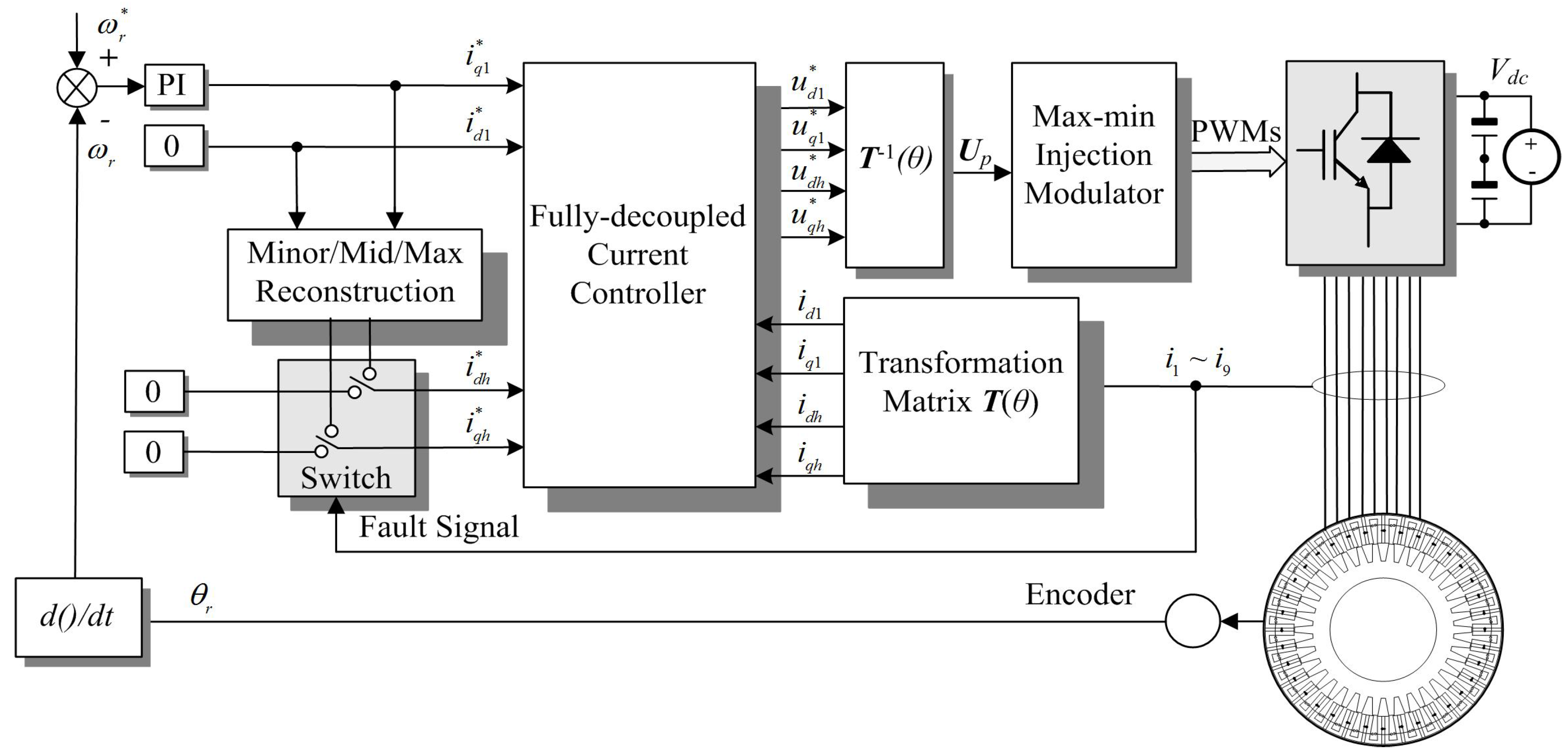
4.5. Closed-Loop Speed Control
On the basis of a fully-decoupled current controller built as inner loop, the closed-loop speed control constructed as outer loop is relatively straightforward in control of the motor to supply the required amount of torque to the load at a given speed. In addition, the torque in an NP-FSPM motor is a function of q1-axis current and stator-PM flux according to Equation (5). Hence, a PI regulator based speed control is directly employed to determine the error between reference speed and actual speed, and generates the torque-producing q1-axis reference current iq1*.
Figure 6 shows the block diagram of the closed-loop speed operation of the NP-FSPM motor. It is a cascade structure made up of one speed controller and four pairs of
d-
q plane current controllers. Furthermore, a software switch is utilized in the controller to select and activate healthy or post-fault operation.
Figure 6.
Closed-loop speed control of NP-FSPM motor for HEV.
Figure 6.
Closed-loop speed control of NP-FSPM motor for HEV.
5. Simulation and Performance Analysis
The simulations were conducted to evaluate the control and performance of the NP-FSPM motor drive. Due to the nature of the machine, the machine parameters vary significantly with load and position. In order to have a realistic representation of the machine, finite-element analysis was used to determine the PM flux linkage, self-inductances and mutual inductances as a function of position and load. As a result, a physical phase variable model built in the MATLAB/Simulink environment was adopted. The phase voltage and electromagnetic torque equations describing the NP-FSPM machine can then be written as:
where
Is = [
i1,
i2,…,
i8,
i9]
T is phase current phasor,
R = diag(
Rs,
Rs,…,
Rs,
Rs) is the phase resistance matrix,
E = [
e1,
e2,…,
e8,
e9]
T is back-EMF phasor,
L(θ) is the stator inductance matrix,
Tc(θ) is cogging torque. The preferred inductance parameters are identified from
dh- and
qh- axis step responses as listed in
Table 3.
Table 3.
Inductance parameters.
Table 3.
Inductance parameters.
| d1-q1 Plane | d3-q3 Plane | d5-q5 Plane | d7-q7 Plane |
|---|
| id1 = 16.6 mH | id3 = 14.9 mH | id5 = 10.5 mH | id7 = 4.1 mH |
| iq1 = 18.3 mH | iq3 = 14.7 mH | iq5 = 9.7mH | iq7 = 4.2 mH |
Firstly, the fully-decoupled current control is applied and tested to evaluate the steady-state performance of the NP-FSPM motor drive. The proportional coefficients of PIs have been chosen in order to obtain a crossover frequency with a safety margin to dead-time, and the integral coefficients of PIs have been chosen in order to get critical damping behavior. The key parameters of those PIs are shown in
Table 4. An outer speed control loop (PI controller) is then added to the control scheme (
Kp_
speed = 0.35, and
Ki_
speed = 16) to evaluate the dynamic performance and reliability. The PWM switching frequency is set to 10 kHz.
Table 4.
Key parameters for inner proportional and integral (PIs).
Table 4.
Key parameters for inner proportional and integral (PIs).
| d1-q1 Plane | d3-q3 Plane | d5-q5 Plane | d7-q7 Plane |
|---|
| Kp_d1 = 320 | Kp_d3 = 250 | Kp_d5 = 50 | Kp_d7 = 150 |
| Ki_d1 = 20 | Ki_d3 = 20 | Ki_d5 = 20 | Ki_d7 = 20 |
| Kp_q1 = 320 | Kp_q3 = 250 | Kp_q5 = 50 | Kp_q7 = 150 |
| Ki_d1 = 20 | Ki_d3 = 20 | Ki_d5 = 20 | Ki_d7 = 20 |
5.1. Steady-State Performance
In this simulation, the driver works in constant current control mode without or with closed-loop harmonic current controller, the
iq1 reference is 2.7 A.
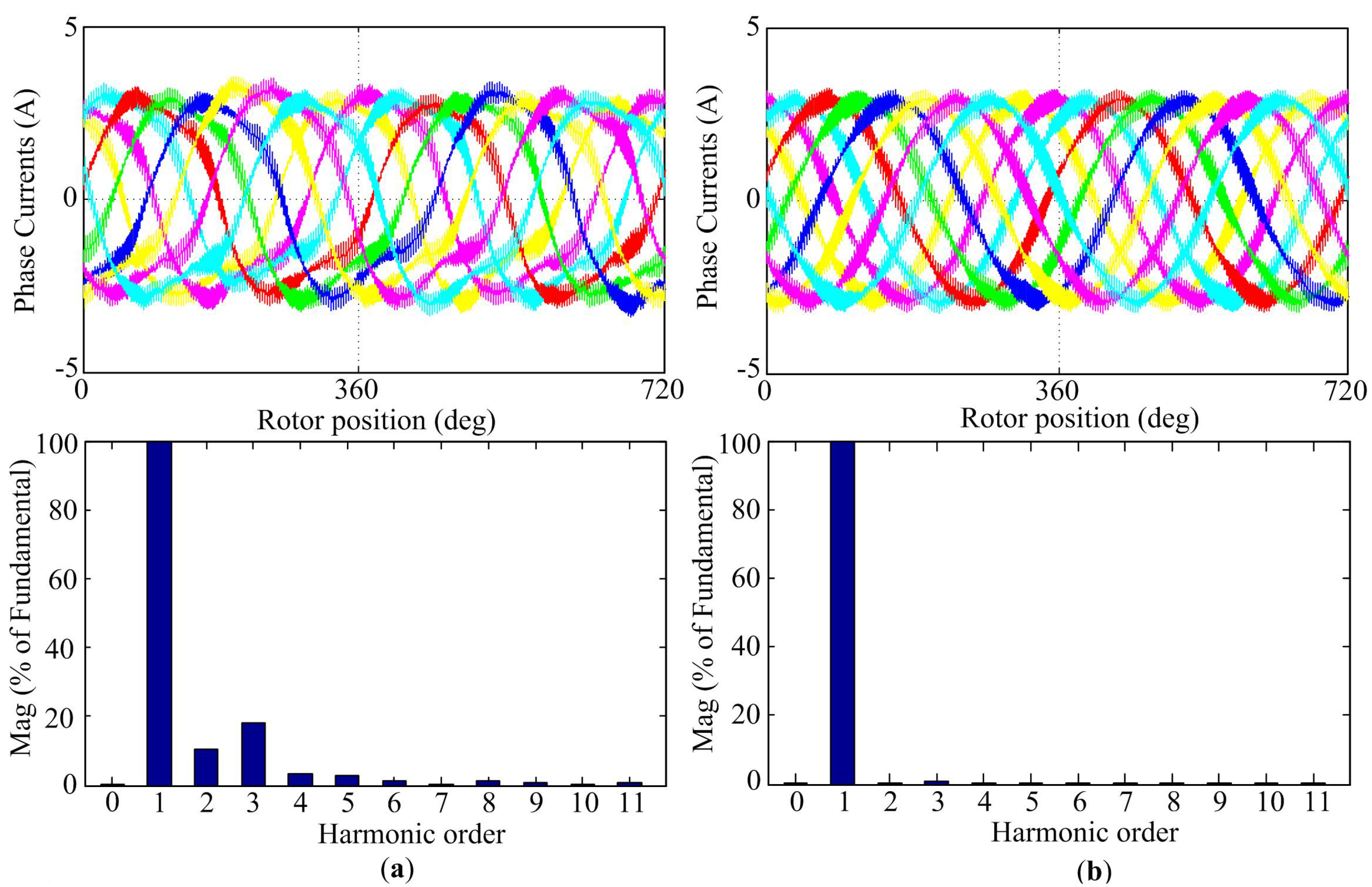
Figure 7a shows the case where current control in the
dh-
qh (
h = 3, 5, 7) plane is omitted. It can be seen that phase current contains rich current harmonics because of the inability of the control to compensate the effect of the non-sinusoidal air-gap flux. As a comparison,
Figure 7b shows the case where fully decoupled current controls are operating as developed in this paper. A major reduction can be seen in the magnitude of the harmonic currents (second harmonic reduces 10% and third 20%), as shown in the FFT result. In addition, the steady-state current errors in the
dh-
qh plane are effectively eliminated when the fully decoupled current control is activated and the
d3-axis and
q3-axis current waveforms are given in
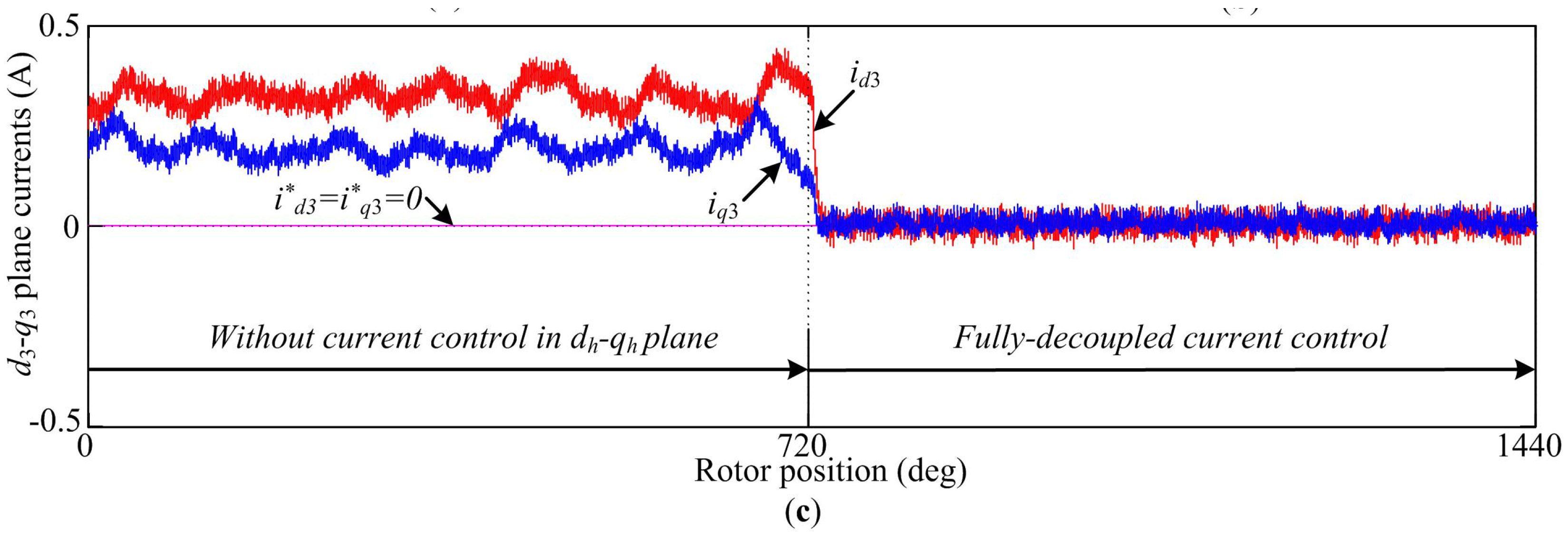
Figure 7c. The results indicate that the fully decoupled current control manages to suppress the low-order harmonics in the NP-FSPM motor, hence ensuring sinusoidal phase currents.
Figure 7.
Simulation evaluation of steady-state performance. (a) Without current control in the dh-qh plane; (b) Fully-decoupled current control; (c) Steady-state current errors in d3-q3 plane.
Figure 7.
Simulation evaluation of steady-state performance. (a) Without current control in the dh-qh plane; (b) Fully-decoupled current control; (c) Steady-state current errors in d3-q3 plane.
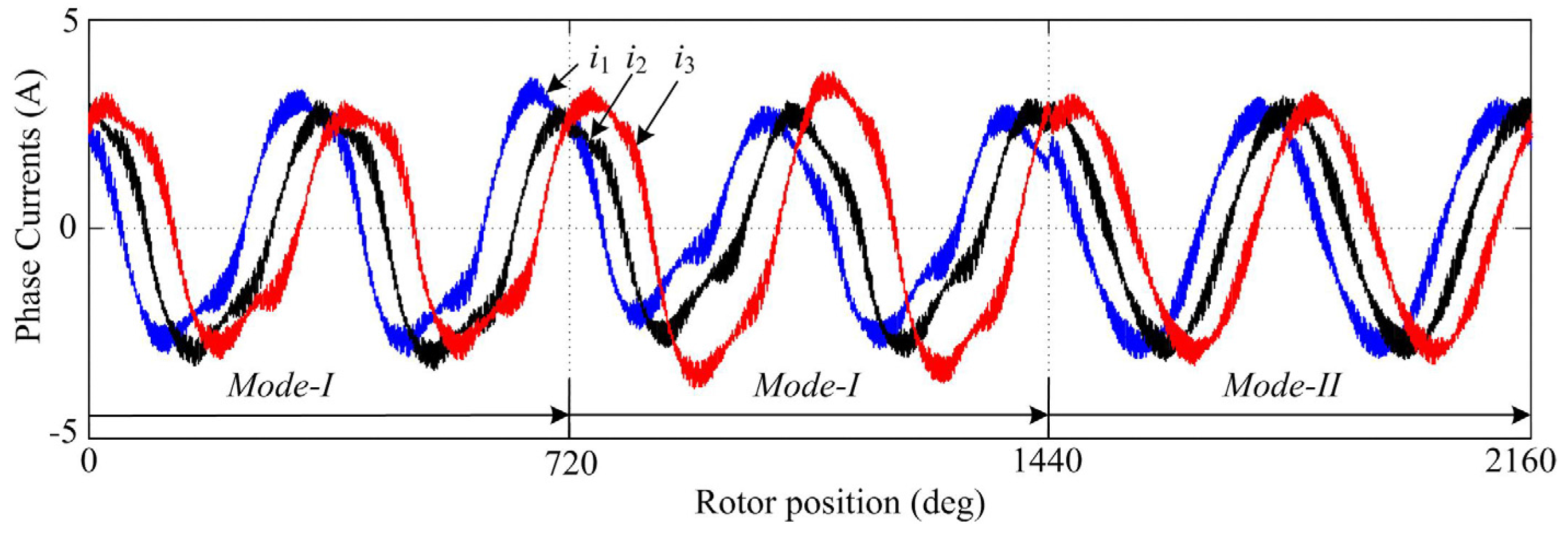
In reality, some key motor parameters, such as stator resistance and mutual inductance, may change during different working states influenced by temperature and magnetic saturation. To verify the sensitivity of the control system to motor parameters, 5 Ω resistances are added between the machine and the VSI of the phases 1 and 2 during the period from 720–2160 deg. For simplicity, the controllers without current control in
dh-
qh plane and with fully-decoupled current control are referred to Mode-I and Mode-II, respectively.
Figure 8 presents the currents of phases 1, 2 and 3, showing that even severe imbalance can be eliminated with fully-decoupled current control.
Figure 8.
Phase currents in the imbalanced condition.
Figure 8.
Phase currents in the imbalanced condition.
5.2. Dynamic Response
For a high performance drive system, the response to the speed control signal should be very fast, and its dynamic transition should be as smooth as possible.
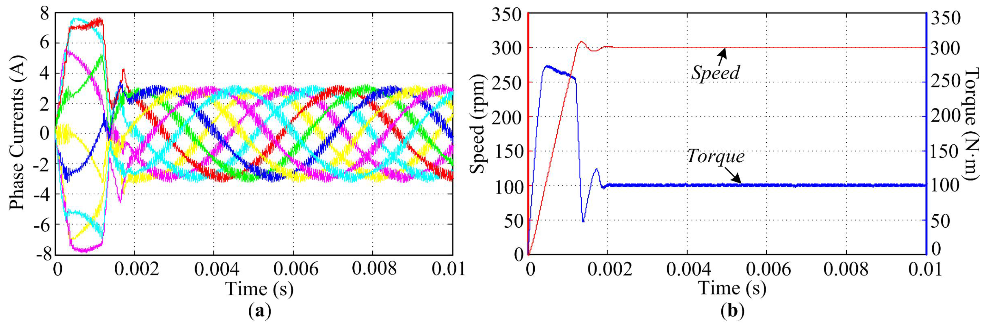
Figure 9 shows the phase current, speed and torque profiles of the NP-FSPM motor after the closed-loop speed operation is established. During the acceleration period, the motor generates near the maximum torque to accelerate the inertia up to the rated speed, taking 0.02 s from 0 to constant 300 rpm, and the controller adjusts the current magnitude to control the speed.
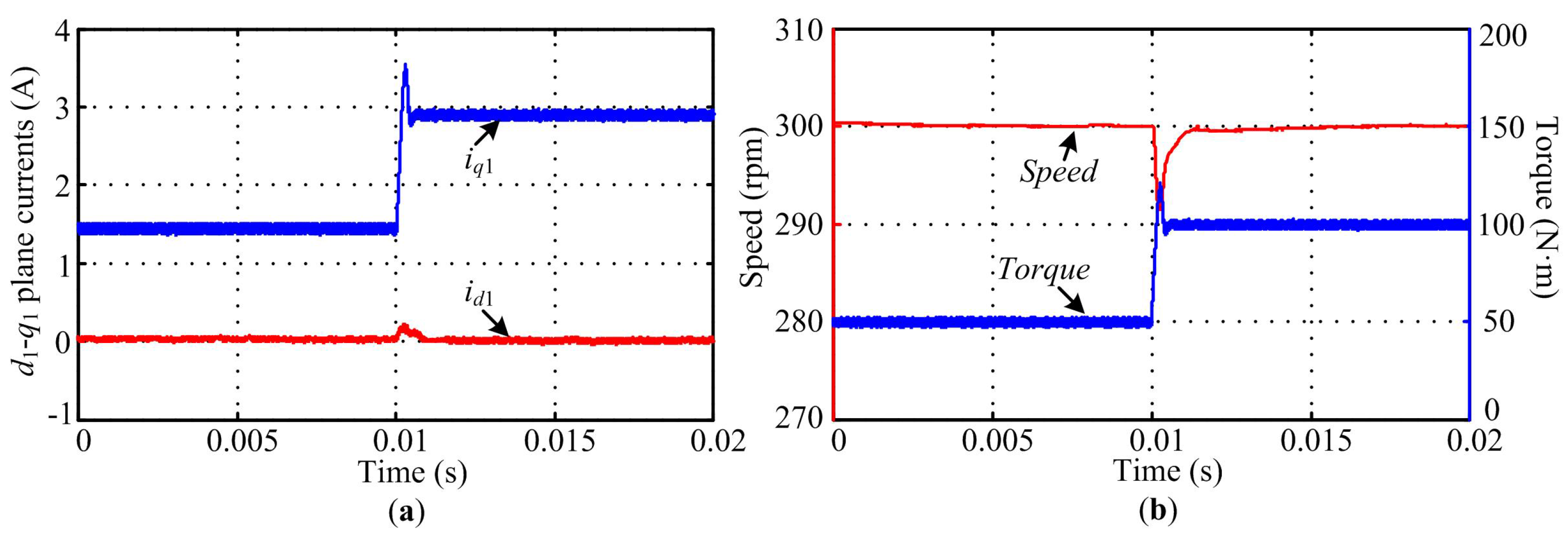
The investigations under different load step changes are carried out and the results are shown in
Figure 10 (starts with 50 N·m at 0 s, then changes to 100 N·m at 0.01 s). Because of the decoupling feedback between the current control axes,
id1 and
iq1 currents can in theory be controlled independently despite simultaneous change of both currents in the transient response, thus enabling fast current changes with negligible disturbance between axes. As seen from
Figure 10b, the speed tracking is accurate but somewhat slow due to the large moment of inertia, with a transient response from 0.01 s to 0.012 s. Nevertheless, the results demonstrate a good dynamic performance of the torque tracking.
Figure 9.
Simulation evaluation of start-up performance. (a) Phase currents response; (b) Speed and torque response.
Figure 9.
Simulation evaluation of start-up performance. (a) Phase currents response; (b) Speed and torque response.
Figure 10.
Simulation evaluation of load step change performance. (a) d1-q1 plane currents response; (b) Speed and torque response.
Figure 10.
Simulation evaluation of load step change performance. (a) d1-q1 plane currents response; (b) Speed and torque response.
5.3. Post-Fault Operations
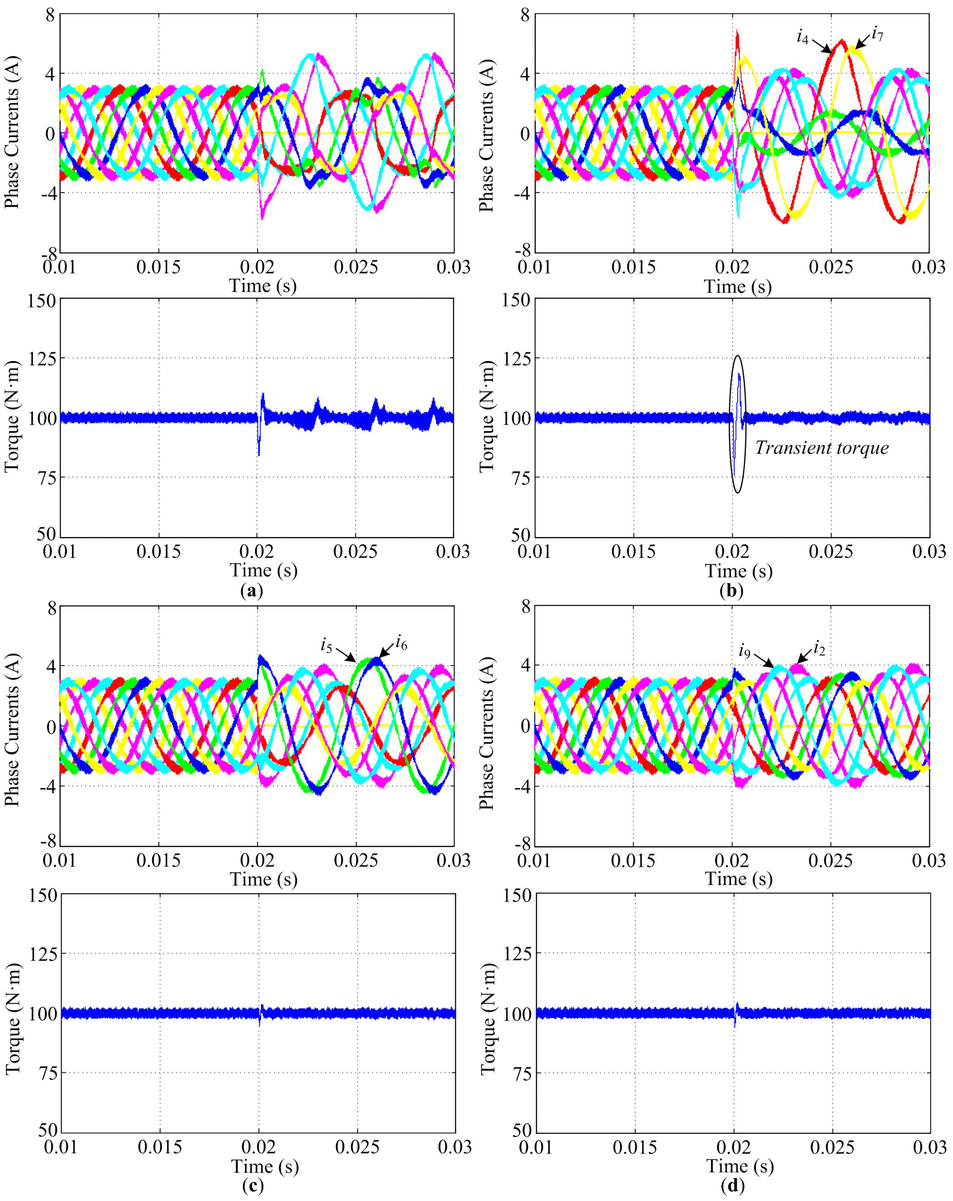
When the open-circuit fault occurs in the phase 1 winding at 0.02 s, the phase currents of the NP-FSPM motor become uncontrollable and a torque ripple of 15% is apparent as shown in
Figure 11a. The simulation results of post-fault operations with Minor, Mid, and MAX Reconstruction modes are shown in
Figure 11b–d, respectively. It can be seen that all the three fault-tolerant modes are able to bring the system back to proper operation. The torque oscillations are efficiently reduced, and the system can be operated continuously and steadily after the open-circuit fault occurrence.
Figure 11b presents the phase currents and torque waveforms by reconstructing only the third harmonic current, the highest peak current value (of phase-4) is about 98% higher than the peak value under the normal condition. It must also be noted that the transient torque is relatively larger. While in the Mid Reconstruction mode as shown in
Figure 11c where both the fifth harmonic and seventh harmonic currents are simultaneously reconstructed, the highest peak value (of phase-6) becomes 41% higher. In the post-fault operation, the minimum peak phase current value can be achieved in Max Reconstruction mode, corresponding to a peak value of 3.8 A (phase-2), as shown in
Figure 11d. Furthermore, negligible transient torque is exhibited in
Figure 11c,d.
Figure 11.
Simulation evaluation of post-fault operation. (a) Faulty operation; (b) Minor Reconstruction; (c) Mid Reconstruction; (d) Max Reconstruction.
Figure 11.
Simulation evaluation of post-fault operation. (a) Faulty operation; (b) Minor Reconstruction; (c) Mid Reconstruction; (d) Max Reconstruction.
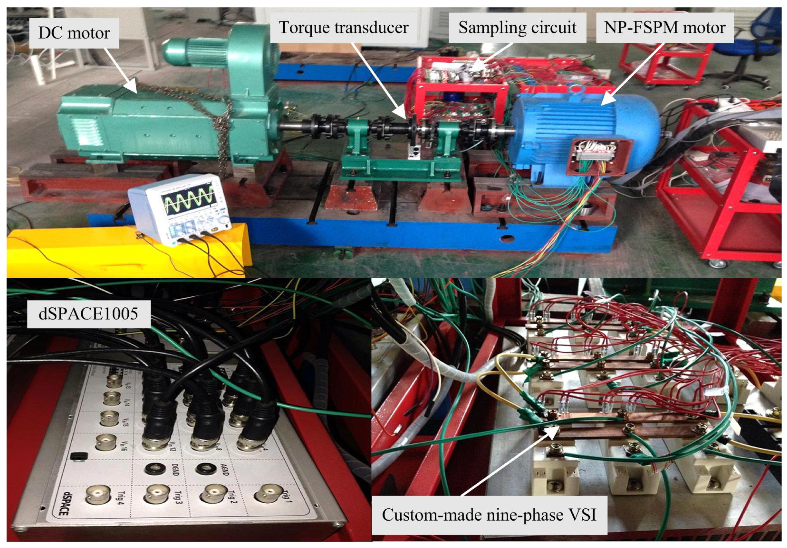
6. Experimental Validation
Figure 12 shows a photograph of the experiment setup. A prototype of 36/34-pole NP-FSPM motor drive has been designed and built for verification. A custom-made nine-leg insulated gate bipolar transistor (IGBT) based inverter is used to supply the motor. A permanent magnet DC motor is mechanically coupled to the NP-FSPM motor as load. The complete control algorithm is implemented on a PC-based dSPACE1005 controller board. Motor phase currents are measured (using the LEM hall-effect current sensors) through dSPACE at a sampling frequency of 10 kHz.
Figure 12.
Experiment setup.
Figure 12.
Experiment setup.
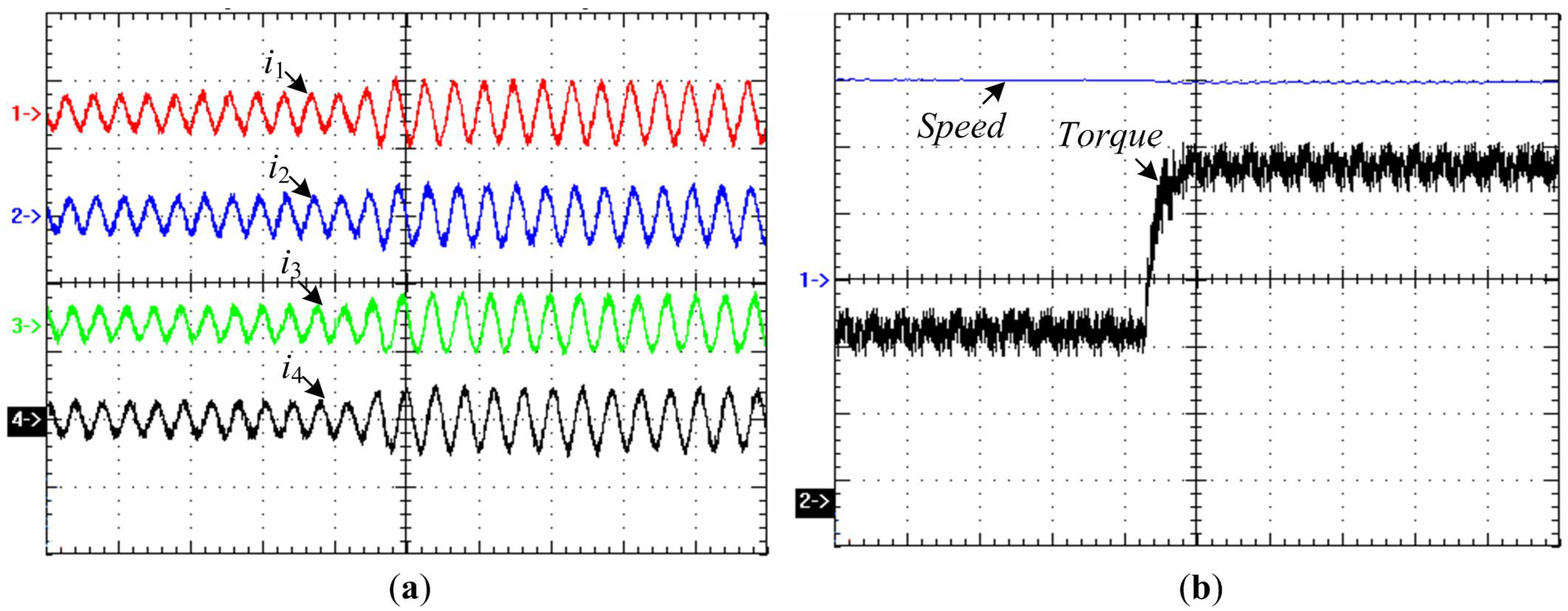
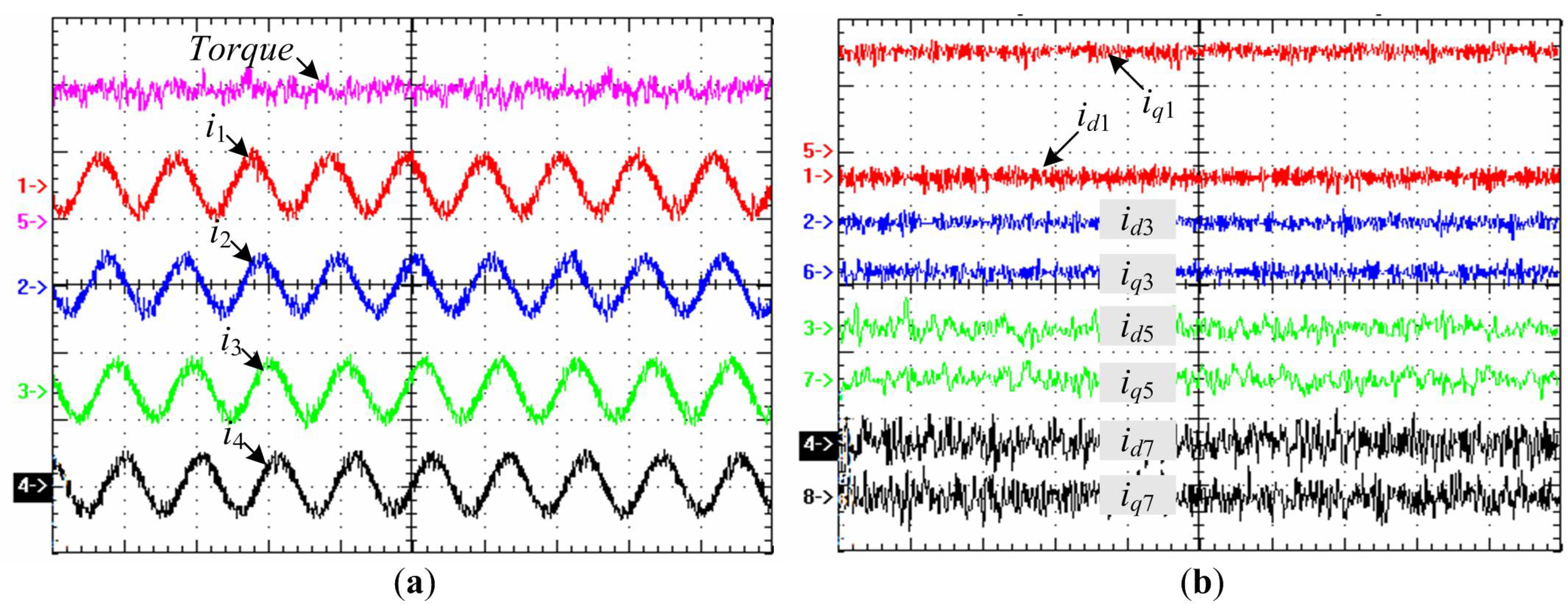
The steady-state performance of the fully-decoupled current control is presented in
Figure 13. As seen in
Figure 13a, the phase current waveforms are sinusoidal and phase-shifted by 2π/9, which are in good agreement with the theoretical ones shown in
Figure 7. In addition, the NP-FSPM motor operates steadily with low torque pulsation.
Figure 13b shows the synchronous current component traces in four pairs of synchronous frames. All the synchronous-frame current components are theoretically controlled at zero, accompanied with a constant value (2.7 A) of stator
q1-axis current, hence ensuring well-decoupled drive system.
Figure 13.
Experimental evaluation of steady-state performance with fully decoupled current control. (a) (Traces 1–4) Measured phase current waveforms, and (Trace 5) measured torque (6 ms/div, 5 A/div, 50 N·m/div); (b) (Traces 1–8) Measured synchronous current components (6 ms/div, 2 A/div).
Figure 13.
Experimental evaluation of steady-state performance with fully decoupled current control. (a) (Traces 1–4) Measured phase current waveforms, and (Trace 5) measured torque (6 ms/div, 5 A/div, 50 N·m/div); (b) (Traces 1–8) Measured synchronous current components (6 ms/div, 2 A/div).
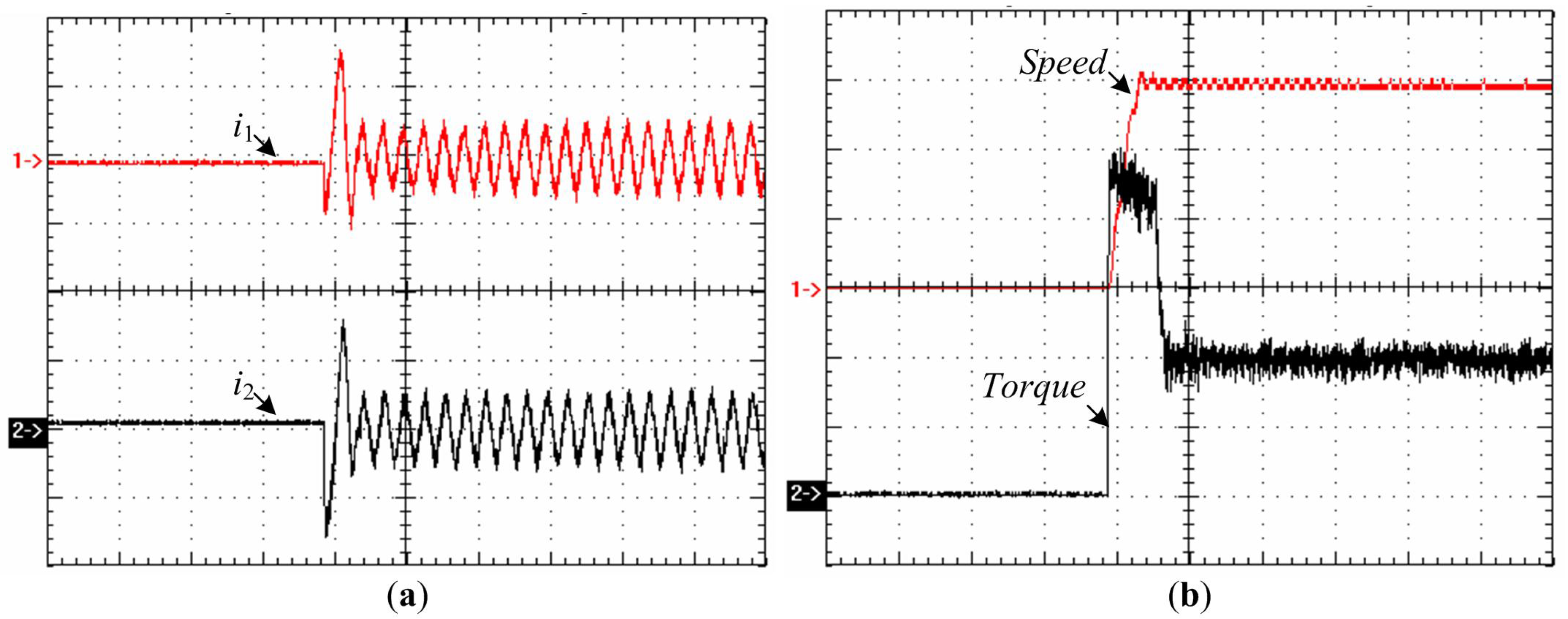
To test the dynamic performance of the closed-loop speed control, the machine starts with 50 N·m load and then changes to the condition of 100 N·m load at 300 rpm. The measured responses under sudden load step-change are shown in
Figure 14, where the motor phase currents and torque follow the load torque rapidly; consequently, the motor speed returns to its reference value in a very short period, demonstrating that the current control provides fast and accurate control, independently of the operation mode of the machine.
Figure 14.
Experimental evaluation of load step-change performance. (a) (Traces 1–4) Measured phase current waveforms (15 ms/div, 5 A/div); (b) (Trace 1) Measured speed, and (Trace 2) measured torque (15 ms/div, 100 rpm/div, 20 N·m/div).
Figure 14.
Experimental evaluation of load step-change performance. (a) (Traces 1–4) Measured phase current waveforms (15 ms/div, 5 A/div); (b) (Trace 1) Measured speed, and (Trace 2) measured torque (15 ms/div, 100 rpm/div, 20 N·m/div).
Figure 15 shows the start-up current, speed and torque responses, confirming that the machine drive offers good self-starting performance. It is worthy of mention that an instantaneous torque of up to 220 N·m can be achieved with an instantaneous peak value of phase current of only 6 A.
Figure 15.
Experimental evaluation of start-up performance. (a) (Traces 1–2) Measured phase current waveforms (25 ms/div, 5 A/div); (b) (Trace 1) Measured speed, and (Trace 2) measured torque (25 ms/div, 100 rpm/div, 50 N·m/div).
Figure 15.
Experimental evaluation of start-up performance. (a) (Traces 1–2) Measured phase current waveforms (25 ms/div, 5 A/div); (b) (Trace 1) Measured speed, and (Trace 2) measured torque (25 ms/div, 100 rpm/div, 50 N·m/div).
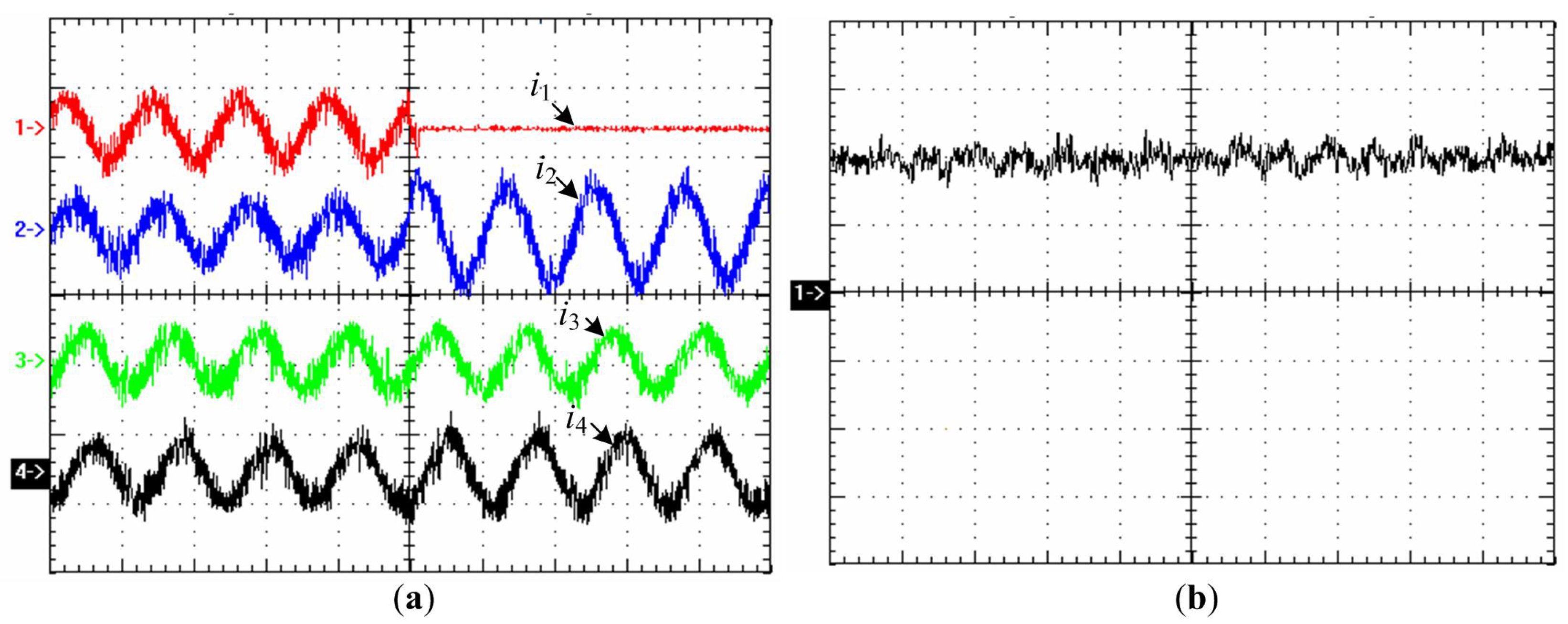
In order to test the fault-tolerance of the NP-FSM motor drive system, an open-circuit fault was forced to occur in phase 1, and the post-fault operation of the NP-FSPM motor evaluated.
Figure 16 shows the response of current and torque before and after the remedial Mid Reconstruction mode (
iα5 =
iα7 = −
iα1/2). As expected, these current waveforms agree well with the simulated results shown in
Figure 11, with negligible torque pulsation during this transient, confirming that the machine drive can achieve disturbance-free operation under fault conditions.
Figure 16.
Experimental evaluation of post-fault operation performance. (a) (Traces 1–4) Measured phase current waveforms (5 ms/div, 5 A/div); (b) Measured torque (5 ms/div, 50 N·m/div).
Figure 16.
Experimental evaluation of post-fault operation performance. (a) (Traces 1–4) Measured phase current waveforms (5 ms/div, 5 A/div); (b) Measured torque (5 ms/div, 50 N·m/div).


