Review

Flywheel Energy Storage for Automotive Applications

Division for Electricity, Uppsala University, Lägerhyddsvägen 1, Uppsala 752 37, Sweden
*
Author to whom correspondence should be addressed.
Energies 2015, 8(10), 10636-10663; https://doi.org/10.3390/en81010636
Submission received: 25 July 2015 / Revised: 4 September 2015 / Accepted: 12 September 2015 / Published: 25 September 2015
(This article belongs to the Special Issue Advances in Plug-in Hybrid Vehicles and Hybrid Vehicles)

Abstract

:
A review of flywheel energy storage technology was made, with a special focus on the progress in automotive applications. We found that there are at least 26 university research groups and 27 companies contributing to flywheel technology development. Flywheels are seen to excel in high-power applications, placing them closer in functionality to supercapacitors than to batteries. Examples of flywheels optimized for vehicular applications were found with a specific power of 5.5 kW/kg and a specific energy of 3.5 Wh/kg. Another flywheel system had 3.15 kW/kg and 6.4 Wh/kg, which can be compared to a state-of-the-art supercapacitor vehicular system with 1.7 kW/kg and 2.3 Wh/kg, respectively. Flywheel energy storage is reaching maturity, with 500 flywheel power buffer systems being deployed for London buses (resulting in fuel savings of over 20%), 400 flywheels in operation for grid frequency regulation and many hundreds more installed for uninterruptible power supply (UPS) applications. The industry estimates the mass-production cost of a specific consumer-car flywheel system to be 2000 USD. For regular cars, this system has been shown to save 35% fuel in the U.S. Federal Test Procedure (FTP) drive cycle.

1. Introduction

The flywheel is an old means of storing energy and smoothing out power variations. The potter’s wheel and the spinning wheel are examples of historical uses of flywheels. The focus in this review is on applications where flywheels are used as a significant intermediate energy storage in automotive applications.
Several tradeoffs are necessary when designing a flywheel system, and the end results vary greatly depending on the requirements of the end application. Examples exist of power flywheels, such as the ABB short-circuit generator (built in 1933 and still in use today), which can deliver a stunning 4000 MVA and short-circuit currents of 100 kA rms for short durations of time [1]. On the other side of the spectrum, one can find a lightweight energy flywheel with a rotor specific energy of 195 Wh/kg [2], which is comparable to that of Li-ion batteries.
Perhaps the most important tradeoff in a flywheel energy storage system is between high power or high energy. A high-power application is relatively simple seen from a flywheel design perspective. A standard high-power electric machine is fitted with some extra weight to sustain the power for a long enough time. A focus on high energy means that the requirements on the mechanical properties of the rotor puts limits on the power transfer units or suspension. Energy flywheels are a main area of research, since this opens up possibilities for new end applications.
Some end applications, for example a flywheel power buffer in a hybrid bus or a Formula 1 flywheel, will release the stored energy relatively soon after charging. This requires an optimization focus on the round trip efficiency (sometimes called AC-AC efficiency), computed as the fraction of input and available output energy:
η a c - a c = E o u t p u t E i n p u t
Other applications, like uninterruptible power supplies for data centers or satellite attitude control, are focusing on the standby efficiency, computed as:
η s t a n d b y = 1 - P s t a n d b y l o s s P d i s c h a r g e
If a system is going to idle at the same speed for 99% of its lifetime, the discharge efficiency is less relevant.
Here follows some important technical tradeoffs in flywheel design.

1.1. Rotor: Mass vs. Speed

The usable kinetic energy stored in a flywheel is the speed interval over which it is allowed to operate:
E = 1 2 J Δ ω 2 = ω m a x 2 - ω m i n 2 2 r 2 d m
where J is the moment of inertia about the axis of rotation; ω is the rotational velocity and dm is a small mass element at a distance r from the axis of rotation. A heavy steel rotor is optimized for high inertia; more energy is attained in a linear fashion by adding extra weight. Steel rotors are usually solid (solid rotors can be shown to be optimal in an energy density sense for isotropic materials [3]). High power is fairly straightforward to attain on high-inertia machines.
Kinetic energy grows quadratically with speed; for a rotating body, this implies that energy for a mass element grows quadratically with radius and rotational speed. Unidirectionally-wound carbon composites exhibit extreme strength in one direction, which implies that a thin rotating shell is optimal, since most of the centrifugal stress is developed in the circumferential direction [3]. By placing mass close to the periphery, it is better utilized (a higher speed at a larger radius results in higher kinetic energy per mass element). Flywheels optimized for high-speed operation are usually of higher energy density, although the high speed can impede power transfer capabilities.

1.2. Bearings: Magnetic vs. Mechanical

The choice between magnetic and mechanical bearings depends on the application; see Table 1. Volume and weight constraints suggest the use of mechanical bearings. However, vacuum operation and low loss requirements suggest the use of magnetic bearings. Magnetic bearings require backup systems for handling delevitation events (planned and unplanned), and although these are maturing [4], industrial standards are yet to be rigidly defined.
Table 1. Comparison between mechanical and magnetic bearings.
Mechanical bearingsMagnetic bearings
High stiffness per volumeLarger footprint for a given stiffness
Known technologyIndustrial standards not yet mature
Must be rated for unbalance forces at high speedsCan allow the rotor to spin around the natural axis at high speeds
Higher standby losses at high speedsVery low standby losses
Lubricants evaporates during vacuum operationGood for vacuum operation
May require active cooling systemsPractical full magnetic levitation requires active control

1.3. Power Transfer: Electric vs. Mechanical

Energy can be transferred into the flywheel either electrically or through a mechanical connection. The current trend is towards electric machines, transferring power in a contact-less manner between rotor and stator. This introduces two important advantages: a long lifetime and low standby losses. Electric machines are typically designed for over 25 years of operation with only bearing maintenance, and magnetic bearings can extend the maintenance-free operation even further.
A purely mechanical flywheel may have its power transmission unit directly connected to the existing drive shaft in a vehicle, and this reduces system complexity, since fewer additional components must be introduced (electric motors, power electronics). However, hybrid vehicles with both electrical and combustion motors are becoming common. Another aspect is that electrified flywheels can be placed more freely, since power is transferred through cables.

1.3.1. Mechanical Power Transfer

Continuously-variable transmissions (CVTs) are used by Flybrid Systems in their Formula 1 Kinetic Energy Recovery System (KERS) [5]. Input discs roll against a conically-shaped disc, and output discs roll against the same disc from the other side, albeit at another angle. High pressure contact between rollers and disc is essential for high power transfer capacity. If the angle is too steep, there will be unwanted slip. There are lower limits to the speed at which power transfer can take place, which may require an additional gearbox to increase the range at which power can be extracted.
The Nuvinci CVT is another concept that involves power transfer through steel balls (like a ball bearing), where each ball has a fixed (but controllable) axis of rotation [6], with input and output discs pressed firmly against the ring of balls.
Belt CVTs have seen widespread use in, for example, snowmobiles. Continuous torque transmission is realized by a belt pressed firmly in between two conical surfaces, the gear ratio being defined by the radius at which the belt is operating. The position of the belt is varied by squeezing the conical surfaces towards each other.
CVT transmissions have traditionally been popular in low-power drivetrains, such as small motorcycles (Vespa type) with low mileage, but they wear out and require maintenance. Audi introduced the “multitronic” transmission in 1999. It required periodic transmission fluid change, and reliability problems were reported. Despite its advantageous performance, it never became popular.

1.3.2. Electric Power Transfer

Due to the high speeds usually involved in flywheels, brushes are avoided, implying no DC machines or wound rotor synchronous machines. A few common types are as follows.

Permanent Magnet Synchronous Machines

The rotor is energized with highly coercive magnetic materials (NeDyFeB or AlNiCo); therefore, no external power is required for the rotor excitation. This leads to the highest charge/discharge efficiencies, but the drawback is that remanent magnetization persists, even though the windings are de-energized (standby mode), producing iron losses in the laminated steel. A way to alleviate this in high-speed machines is a coreless stator as used by Beacon Power [7] and Uppsala University [8].
Magnetic material is typically very brittle; the ultimate tensile strain for neodymium magnets is only 0.06%. Magnets mounted on the inside of a composite rim can thus impose a serious limit to the maximum speed of the machine, since the ultimate strain limit of composites is far higher, above 2%.
There is a development towards magnetically-loaded composites in flywheels, to enable higher rotational speeds; either iron powder in the epoxy matrix [9] or magnetized magnetic powder [10]. The latter technique has been successfully implemented by GKN Hybrid Power (until 2014 known as Williams Hybrid Power, but hereinafter referred to as GKN).
Lockheed Martin has been working with flywheel composites with iron filaments added to the epoxy matrix. The relative permeability was shown to be around 13, and the magnetically-active composite was shown to have a linear magnetization behavior [9]. These can be used to build flywheels with extremely high speeds, so-called “hollow-cylinder” flywheels, which are shaft-less [11,12]. The motor would then be directly integrated into the high-strength composite. There are several university groups working towards this goal, such as Arlington University and the University of Sheffield [13,14].

Induction Machines

Inductance motors/generators generally have lower power density and efficiency than permanent magnet motors, but the lack of permanent magnetization significantly reduces the issue with electromagnetically-induced idling losses. The rotor is mechanically fairly simple and robust, although a significant portion of the losses are generated there. For flywheel rotors suspended on magnetic bearings in a vacuum, the rotor losses must be kept low to avoid overheating. The only cooling mechanism in that case is the very limited black-body radiation. Stationary flywheels with inductance motors/generators have been reported [15,16], but higher power density topologies are preferred in mobile applications.

Reluctance Machines, Switched or Synchronous

Reluctance machines achieve high efficiency operation at a great range of speeds; the standby losses are fairly low, and no rare earth materials are used in the construction. There is a trend to reduce the use of rare earth materials, such as neodymium and dysprosium, especially in Japan [17], and research interest in reluctance machines is increasing. Permanent magnet motor performance has been achieved with reluctance motors by using high performance materials [18].

1.4. Materials, Containment and Safety

Flywheels can be built with non-hazardous materials. Typical materials are steel (including electrosteel), aluminum and/or titanium; carbon composites, E-glass and/or S-glass; epoxy or pre-preg matrix; and lastly, magnets, such as NeDyFeB, AlNiCo, or others.
Since heavy-duty containment chambers are not an option in mobile applications, there is a strict requirement of safe catastrophic failure modes. State-of-the-art flywheel models go through rigorous testing to ensure safe failure behavior [19]. Composite rotors have been shown to have benign failure modes [20], and lightweight vacuum chambers with a technology similar to that of bulletproofs vests have been developed.

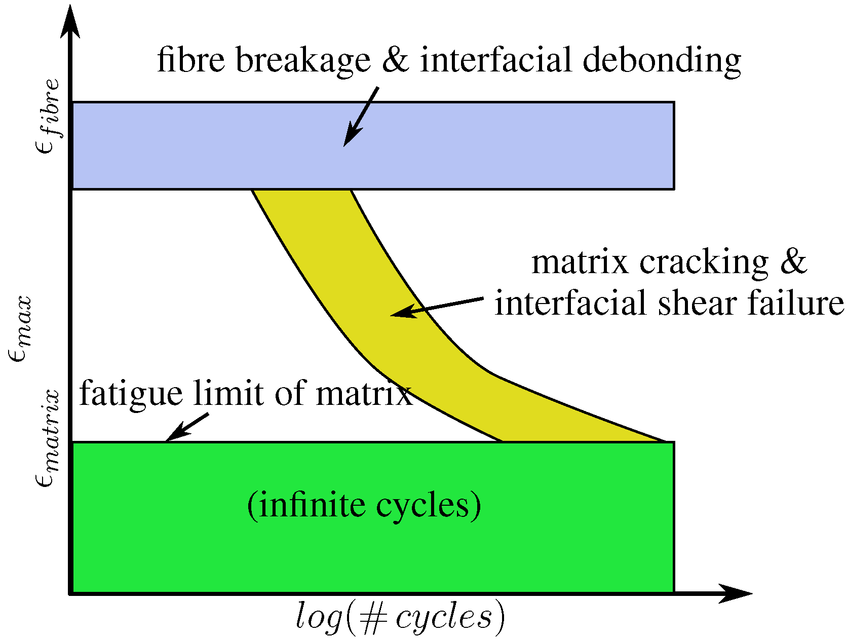
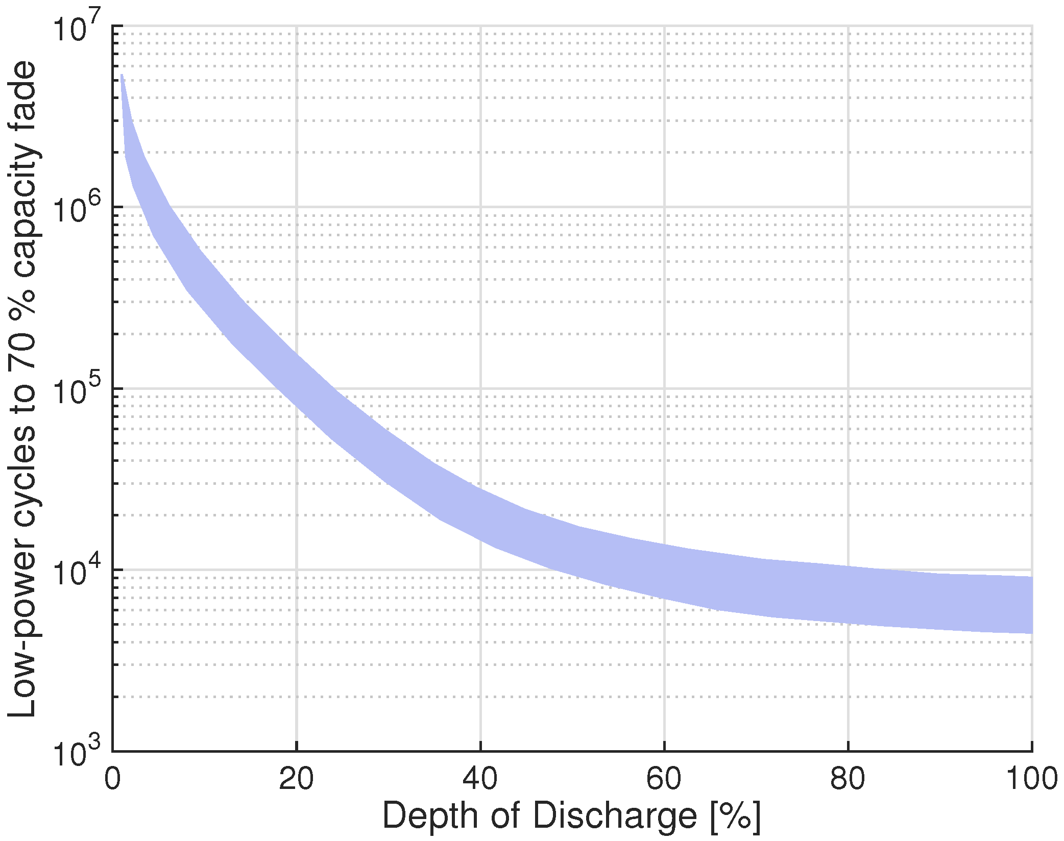
1.5. Cycle Life Time

Flywheels have been shown to have excellent aging characteristics, with cycle lifetimes in excess of 1,000,000 cycles, regardless of charge rate and depth of discharge [21]. The critical component in any modern high-speed flywheel is the carbon composite, and the fatigue of composites is a complex process. In general, material fatigue is directly connected to cyclic loading. For composites, the ultimate fatigue limit (infinite cycles) is dependent on the binding matrix, which for epoxy is 0.6% in the hoop direction (main stress direction) [22]. See Figure 1 for a graph of strain versus the number of cycles in a unidirectional composite.
It is important to note that the 0.6% limit is not related to the charge/discharge profile, but rather to the flywheel state-of-charge. This implies that as long as the state-of-charge of the flywheel does not exceed a certain threshold, a very long cycle life can be guaranteed.
Figure 1. The number of cycles to failure as a function of strain. The fatigue limit for composite flywheels is directly related to the strain in the matrix [22].
Energies 08 10636 g001

1.6. Future Potential

The limit of rotational energy that can be stored in a material is often calculated with the following approximation [3]:
e = E m = σ θ 2 ρ
where e is the energy E per mass m; σ θ is the tangential stress and ρ is the material density. The approximation is valid under the assumption of a rotating thin-walled cylinder, useful for comparing different materials, although realistic flywheel designs are of lower specific energy.
In Table 2, the future potential of flywheel energy storage is assessed by comparing contemporary materials with a few novel ones. The carbon nanotube example may seem unrealistic today, but has received interest from both NASA [23] and the U.S. Department of Defense [24].
Table 2. Theoretical potential for flywheels with contemporary and future materials.
MaterialUltimate tensile stress (MPa)Density (kg · m - 3 )Rotor energy density (Wh/kg)
Aluminum 7075572281028
17-7 PH Stainless steel1650780029
Titanium Ti-15V-3Cr-3Al-3Sn ST 790 °C1380476040
Advantex E-glass (glass fiber)∼1400214690
Toray T1000G composite30401800234
Toray T1000G fiber63701800491
Vapor grown carbon nanofibers [25]29202000202
Single wall carbon nanotube (low end) [25]50,00013005341
Single wall carbon nanotube (high end) [25]500,000130053,418
Multi-walled carbon nanotubes (low end) [25]10,0001750793
Multi-walled carbon Nnanotubes (high end) [25]60,00017504761

2. Understanding the Flywheel Niche

There are primarily four properties that make the flywheel attractive for use as energy storage:
  • High power density;
  • Long cycle life;
  • No degradation over time and;
  • Easily estimated state-of-charge.
Taking advantage of the first two properties leads to systems with high and very frequent flows of energy. One example of this is using the flywheel as a buffer for smoothing frequent fluctuations, e.g., in the grid.
Taking advantage of the first and fourth properties leads to systems with high, but rare flows of energy, but where correct information regarding the state-of-charge of the storage system is critical. One example of such a system is the uninterruptible power supply (UPS). In a battery system, the aging processes can increase the internal resistance, while an SoC estimation from the measured voltage does not reveal this [26].

2.1. Depth-of-Discharge

The cycle life of flywheels is not directly related to depth-of-discharge; however, this is the case for batteries. This is important when defining the niches for flywheel energy storage.
Batteries degrade when cycled, when discharging at high rates and at high temperature [26]. The degradation affects energy capacity and power capacity, the latter through an increase in internal resistance. For an application with a requirement of 10 6 cycles, a battery pack can only be run at a depth-of-discharge of 3% (as seen in Figure 2), which implies that a battery that is 33-times larger must be bought. The specific energy then also decreases with the same factor. The particular specific energy may well be lower than a flywheel system.
Figure 2. Cycle life of a battery as a function of depth-of-discharge in a low-power application [27]. The end of usable life is assumed to be 70% capacity.
Energies 08 10636 g002
The statistics of the discharge depths is very important when considering end applications for energy storage. Assume the following two cases.

2.1.1. High Variations on the Required Cycle Energy

This case is applicable for the regular car owner. The average trip distance for a car in Europe is only 15 km [28], but people want to have the capacity to drive 500 km or more. The average number of trips per day is also less than three. The electric car manufacturer Tesla Motors markets their car as having a range of 434 km, with Li-ion batteries as the only energy storage [29]. Depending on the depth-of-discharge, the max range cycle life is around 2000 cycles (driving the max range every day for six years). However, since the average use case for people is much less than that, the typical depth of discharge is only 3.5%. That means that the battery lasts for 1,000,000 average cycles or longer than the lifetime of the car (from a depth-of-discharge aging point of view).
1 , 000 , 000 c y c l e s 3 a v e r a g e c y c l e s p e r d a y * 365 d a y s = 936 y e a r s
In essence, the electric car buyers are not buying a high-capacity battery only for the maximal range, but for limiting the depth-of-discharge, so that the battery lasts the entire lifetime of the car.

2.1.2. Few Variations on the Required Cycle Energy

The second case is characterized by small changes in the required energy per cycle. Many applications fit into this niche:
  • Power buffers in drive lines where the power density is low in the prime energy carrier, such as:
    Low-power, high-energy batteries (such as Li-air);
    Fuel cells (slow response times, low power density);
  • Power buffers in drive lines where a steady (~constant) power flow from the primary energy source is advantageous, such as hybrid drive lines with combustion engines (higher efficiency, higher torque and less emissions with constant power outtake);
  • Car ferries with short predefined trips (e.g., ~10 min, 50 times a day);
  • Cranes lifting containers of roughly the same weight every time;
  • Garbage trucks, which accelerate and decelerate in front of every house and frequently compress the garbage;
  • Train station energy storage, which captures the energy of a braking train.
In Table 3 is a comparison of different technologies for a power buffer application in a city bus drive line.
Table 3. GKN Hybrid Power reported the listed comparison between three specific system implementations of a power buffer application in a vehicle [21]. Five hundred Watt hours corresponds to the kinetic energy of a city bus moving at 50 km/h. EDLC, electric double-layer capacitor.
TypeFlywheel systemEDLC systemLi-ion battery system
ManufacturerGKNMaxwell BoostcapA123Systems
Rated power120 kW120 kW120 kW
Energy capacity456 Wh647 Wh26,400 Wh
Cycle life time > 10 6 10 6 10 3
Specific energy8.3 Wh/kg1.75 Wh/kg110 Wh/kg
Specific power2200 W/kg320 W/kg500 W/kg
System weight55 kg370 kg240 kg

2.2. Flywheel Costs

It is difficult to compare the cost of flywheels and batteries, since the latter are mass produced, while the former are not. However, the raw material costs are known to comprise about 60%–70% of the costs in large-volume manufacturing of electrical machines [30]. GKN Hybrid Power themselves compare the raw material cost of a standard internal combustion engine to about 685 USD, while a low-power, low-energy flywheel (30 kW/111 Wh) costs about 723 USD (5% more) [19]. Flybrid Systems reported a cost comparison in 2008, seen in Table 4.
Table 4. A technology comparison as presented by Flybrid Systems [31].
ParameterFlybrid systemElectric hybrid
Round trip efficiency74%34%
Weight35 kg85 kg
Volume20 liters50 liters
Cost per unit (200k units)2000 USD8000 USD
In 2010, Volvo together with Flybrid Systems, asked SKF to investigate the costs of mass-produced flywheel power buffers (in comparison to other hybrid vehicles) and reported: “The final cost estimate comprised manufacturing, purchasing, fabrication and testing—the results of the study was presented to Volvo—and the reactions were positive.” [32].
Advanced electromechanical flywheels have components that have been traditionally very expensive; however, key technologies are decreasing in price due to recent developments in other sectors. High-precision eddy-current positions sensors for magnetic bearings cost around 5000 USD for Uppsala University to buy in 2009, but in 2015, a system with similar performance cost less than 60 USD. This is due to the fact that multi-layered PCBs can be reproduced with high precision, allowing inductive sensors to be mass-produced inexpensively. Power electronics are having their costs pushed down each year by the electric car and power industries. Processing power for advanced control is becoming less expensive every year and has been following the popularized Moore’s law in cost decrease since the 1950s. Composite materials development is driven by the wind power and transportation industries.

2.3. Flywheels vs. Supercapacitors

Supercapacitors are competing with flywheels in high-power applications. The market leader of electric double-layer capacitors (EDLCs) is currently Maxwell Technologies [33]. They have a specially-designed power buffer for vehicles, which can be bought off the shelf for 6500 USD [34]; however, the price is likely to come down for large volumes. A comparison between three flywheels and the EDLC system specially designed for “heavy duty transports” can be seen in Table 5.
Table 5. A comparison between state-of-the-art supercapacitors and three state-of-the-art flywheels.
Flywheel systemFlywheel systemFlywheel systemEDLC system
GKN hybrid power Porsche GT3R [21]GKN hybrid power Audi e-tron [21]Flybrid Formula 1 2009 [3]Maxwell Technologies BMOD0063 P125 [35]
180 kW150 kW60 kW103 kW
375 Wh97 Wh111 Wh150 Wh
>1,000,000 cycles>1,000,000 cyclesN/A~1,000,000 cycles
6.4 Wh/kg3.5 Wh/kg4.4 Wh/kg2.3 Wh/kg
3.15 kW/kg5.55 kW/kg2.4 kW/kg1.7 kW/kg
57 kg27 kg25 kg61 kg

2.4. Flywheels vs. Batteries

Flywheels’ biggest competitor in most areas of use is batteries. However, flywheels have, as mentioned earlier in the chapter, advantages over batteries.

2.4.1. Specific Power

As seen in Table 5, state-of-the-art mobile flywheel systems have 6.4 Wh/kg or 5550 W/kg, respectively. Batteries can be optimized for either power or energy, for example SAFT Li-ion batteries come in high-power cells of 61 Wh/kg and 1150 W/kg and high-energy cells of 144 Wh/kg (for the whole system) [36].

2.4.2. Usable Life

Both cycle life and lack of degradation over time speak in favor of flywheels, as discussed above and seen in Figure 2.

2.4.3. Environmental Footprint

The environmental footprint of flywheels can potentially be very small, as flywheels can be built with non-hazardous materials and are easy to recycle.

2.4.4. Temperature Sensitivity

Flywheels are generally less sensitive to the ambient temperature than batteries. Some important thermal limits are set by the temperature in: the windings, to avoid melting; the magnets, to avoid demagnetization; and the composite material, to avoid burning it.
Li-ion batteries experience both capacity and power fade at higher temperatures [26].

2.4.5. State-of-Charge Estimation

There are various techniques to estimate battery state-of-charge (open circuit voltage, terminal voltage, impedance spectral estimation, Coulomb counting, etc.) [37] with varying performance during different operating conditions. For a flywheel energy storage, the state-of-charge is directly measurable from the rotor speed.
There are four areas where batteries, for the time being, are decidedly better than flywheels:
  • Energy density;
  • Self discharge;
  • Steady output voltage;
  • Cost per kWh.
Regarding costs, battery prices have decreased significantly in the last decade. The yearly decrease is 14% between 2007 and 2014 [38], to about 300 USD/kWh in 2015. The driving force behind this development is mass production.

3. Applications

Not all applications listed below are strictly automotive; however, technology developments in related areas are important for flywheel technology in general.

3.1. Buses

An ordinary Swedish bus runs about two million km before it is taken out of service for good. If the bus is operating in urban areas, this means a huge number of starts and stops, making the flywheel a very interesting option for the power handling system on board. Flybrid Systems report a 45% fuel savings for a 17 metric tonnes bus on the London bus drive cycle [31].
The first flywheel buses were the gyro-buses, developed by the company Oerlikon during the 1940s. They relied on the principle of a big and slow steel flywheel. The flywheel weighed 1500 kg and had a diameter of 1.6 m. The energy storage capacity was 6.6 kWh at 3000 rpm rotational speed [39].
The first two buses were shown to the public in Switzerland in 1950, and they were operating for ten years. The concept was brought to Congo, where twelve buses were operating. Some years later, 1956, Belgium was the next country to adopt the gyro-bus. By the beginning of the 1960s, all of the buses were gone from the streets. The reasons for the early retirement were high energy consumption, a great need for maintenance and repair and wearing of the road due to the heaviness of the buses [40].
After these first attempts, the development of the modern flywheel, light and fast, consisting of composite material (and sometimes suspended magnetic bearings), was beginning to take off. In the 1990s, at the University of Austin, Texas, a bus was equipped with a modern flywheel. This flywheel could store 2 kWh and was rated for 150 kW of continuous power [41,42]. They reported a flywheel for pulsed loads in a military vehicle in 2001 [43]. Another study presented the use of a small flywheel buffer for a fuel cell bus [44].
CCM is a Dutch company that has a long experience with flywheels for hybrid and electric propulsion. A successful test application was presented in 1996 in a city bus in Eindhoven. This test bus was 12 m long and 18 tons and was powered with a small (40 kW) liquified petroleum gas-fueled generator set for the average power supply and a flywheel system (200 kW/2 kWh) for the peak power management, including brake energy recovery. The bus showed up to a 30% fuel savings and a 90% emission reduction [45,46].
In London, there will soon be 500 buses out on the streets, equipped with a 0.4 kWh flywheel, enough to accelerate the bus from 0–50 kph and recover the energy when braking. This system is saving about 20%–25% of the energy, provided from diesel, implying yearly savings of around 5300 liters per bus. The payback time is assumed to be five years. Another advantage is that the flywheel system can be installed in existing buses, making the hybridization relatively inexpensive, smooth and easy [47,48,49]. The manufacturer, GKN Hybrid Power, is a part of GKN, which is listed on the London stock exchange and has a market cap of 5 BUSD.

3.2. Cars

In the last decade, the development and introduction of flywheels for use in cars have accelerated. One driving force is the presumed legislation regarding fuel consumption in cars and the consistent reduction of CO 2 emissions, where the target for 2020 is set to <80 g CO 2 per km. Furthermore, vehicle performance and local environmental concerns, like emissions and noise, are favorable with a hybridization.
In Formula 1, the flywheel has been used as a temporary energy storage since the rules were changed in 2009, allowing such equipment. The supplier of this KERS (Kinetic Energy Recovery System) was the company Flybrid Systems [5]; see Figure 3 and Table 6.
Figure 3. Flybrid Systems Formula 1 flywheel for the 2009 season. Note that the power requirements are quite high, and the mechanical power transfer system (a continuously-variable transmission) is a large part of the machine. Reprinted with permission from the copyright holder.
Energies 08 10636 g003
Table 6. The specifications for the Flybrid systems Formula 1 flywheel.
PropertyValue
Usable energy111 Wh
Power capability60 kW
Max rotor speed64,500 rpm
Rotor weight5 kg
System weight25 kg
Specific energy (rotor)22.2 Wh/kg
Specific energy (system)4.4 Wh/kg
Energy density8.5 Wh/L
Flywheels in motorsport have several charge/discharge cycles per minute, so stand-by losses are not a major issue. However, conventional driving patterns have higher standby efficiency requirements.
Flybrid Systems reported an 18% savings for a 1.7 ton saloon car on the New European Driving Cycle (NEDC) test cycle and a 35% saving for a 2.6 ton SUV on the U.S. Federal Test Procedures (FTP) driving cycle [31]. The implemented flywheel energy storage systems are focused on providing power, off-loading a high-energy/low-power source. Flybrid Systems was bought by Torotrak PLC in 2014. Torotrak is listed on the London stock exchange and has a market cap of 23 MUSD.
Jaguar used a mechanical flywheel system from Flybrid Automotive in their hybrid car Jaguar XF from 2011. The flywheel is made of composite, and the transmission to the driving wheels is made by a Torotrak/Xtrac CVT gearbox. The system weighs 65 kg and stores 120 Wh at 60,000 rpm. The maximum power to be delivered is 60 kW. The fuel savings is around 20% [50]; see Figure 4.
Figure 4. Jaguar hybrid car flywheel. Reprinted with permission from the copyright holder.
Energies 08 10636 g004
Furthermore, Volvo is on track to use mechanical flywheels for power handling. Their flywheel from Flybrid Systems, installed in a Volvo S60, is similar to the one from Jaguar, allowing a 60 kW boost and around a 20% reduction in fuel consumption [51].
The Williams Formula 1 team developed a system similar to Flybrid Systems’, but it was never used during an Formula 1 race. Nevertheless, their technology has been used in other races, such as the Le Mans 24 h race in 2012, where an Audi R18 e-tron quattro became the first hybrid car to win the race. The magnetic part of their flywheel rotor consists of magnetically-loaded composite material instead of solid magnets. The rotor is also rotated in a partly depressurized environment to decrease the peripheral drag losses at the same time as allowing the bearings to operate in atmospheric pressure. The storage capacity is 140 Wh, and the rated power is 150 kW [52,53,54]. A photo of a GKN Hybrid Power flywheel can be seen in Figure 5.
Figure 5. GKN Hybrid Power Flywheel. Reprinted with permission from the copyright holder.
Energies 08 10636 g005
In 2010, Porsche launched the racing car Porsche 911 GT3 RS Hybrid. It is equipped with an electric 120 kW flywheel power buffer from GKN Hybrid Power. The flywheel is charged only by braking and can be fully charged, and recharged, in 6–8 s. The maximum speed is 40,000 rpm [55].
DTI, Punch Powertrain, CCM, Bosch, SKF and Technical University of Eindhoven (TU/e) joined forces in the EcoDrive project to develop a mechanical system for hybrid heavy vehicles. It consists of a steel flywheel for energy storage and a push-belt CVT (continuously-variable transmission) for power transmission [56]. The flywheel unit is 150 mm in diameter and weighs about 20 kg. The rotational speed is 35,000 rpm, and standard bearings are used. TU/e has also been involved in the design and development of electromechanical flywheels for regenerative energy storage in mobile applications. They developed a system together with CCM, called EMAFER (Electro Mechanical Accumulator For Energy Reuse) [57].
Uppsala University has been performing research in the field. So far, three Ph.D. theses have been written within the flywheel subject. The main focus has been car drive line systems, but in later years, there has been some focus on other applications, as well, such as grid energy storage, wind power smoothing, cable ferries and larger vehicles, such as buses and garbage trucks [3,8,58,59,60,61,62,63,64,65].

3.3. Container Cranes/Straddle Carriers

Container cranes (also known as straddle carriers) are operating in ports and other areas where goods are handled. A lot of energy is used to move and pile heavy containers, and the energy is supplied by a diesel generator, providing the hoist motor, the gantry motor and the trolley motor with electricity. When reversing these motors, for example when lowering a container, the energy recovered is wasted as heat in a resistor bank. A clear business case for a flywheel is to store this energy and release it when it is needed again. There are considerable amounts of energy to be saved: an 8 m lift of a 50 ton container corresponds to more than 1 kWh of energy. A crane working in shifts, lifting 60 containers per hour in a busy port, will reach 100,000 cycles within three months.
A test was performed by the Center for Electromechanics, University of Texas, Austin, USA, and VYCON Inc., Cerritos, CA, USA. Two flywheel unit systems were installed in a container crane. The flywheels were rated for 60 kW each and could store 0.3 kWh each, with speeds spanning between 10,000 and 20,000 rpm. From data from the ports of Los Angeles and Long Beach, CA, USA, it is assumed that every container takes a minute to handle, and the typical weight of a shipping container is 15 metric tonnes (to add to the 10 metric tonnes weight of the spreader that grabs the container). An energy savings for a single crane of around 100 MWh per year is theoretically possible, assuming operation 10 h a day, 365 days a year.
The test results were very promising, yielding a two-way efficiency of the complete system of 46% (most of it related to mechanical losses in the hoist system, not to the flywheel system). The fuel consumption was reduced by 21%, emissions of nitrous oxides by 26% and particulate emissions by 67%. It is also worth noticing that the number of cycles, 100,000–200,000 per year, would be hard to achieve with batteries, since their lifetime would be severely compromised [66,67].

3.4. Construction Machines

The case for some construction machines is the same as for straddle carriers: many starts and stops, together with many heavy lifts. The main advantage might be that the diesel engine can be downsized and run with a higher average efficiency, since the flywheel takes care of the sudden peak powers.
Ricardo has built a 101 kW/55 Wh flywheel, with specific power/energy of 1 kW/kg and 0.55 Wh/kg, respectively. The application is a 17 ton excavator, saving 10% of fuel under typical conditions. They estimate the fuel savings to be substantially greater if coupled with a downsizing of the main engine together with improvements in the hydraulic system. Note that this is for a semi-stationary excavator. For a wheeled loader application, the potential benefit is deemed greater, although with added technical difficulties. The flywheel is operating in a permanent vacuum, and energy is transferred in and out to the flywheel via a magnetic coupling device [68].

3.5. Garbage Trucks

Garbage trucks are a very interesting application for flywheels. The frequent start-and-stop behavior (and periodic high-power compression of the garbage) is ideal for recovering the energy with a flywheel.

3.6. Charging Stations

Charging stations represent high-power loads in the grid, and energy storage can mitigate the need for local grid strengthening measures. Furthermore, some projects aim to combine renewable energy sources in charging stations [69]. Local production has economical advantages, as the cost of electricity transport is highly reduced. There are several ongoing projects of charging stations with energy storage, as the ABB’s “flash charging” system for electric buses [70]. Flywheels are a competitive alternative to the super capacitors used in these projects.

3.7. Cable Ferries

There is a great potential in hybridizing cable ferries with flywheels. They have all the prerequisites: many cycles (this can easily be more than 30,000 cycles/year), high power demands, but relatively little energy to be stored. In addition, ferries are not so sensitive to additional volume or weight. For high-inertia steel flywheels, the gyroscopic force of the flywheel can be used to stabilize the ferry in rough seas [71]. A case study shows that there is also a considerably amount of money to save on hybridizing cable ferries. A total cost reduction of 480,000 USD (net present value) is possible, assuming a conservative scenario. The lifetime of the flywheel and the diesel price are the two main components of the total cost reduction [58].

3.8. Train Stations

When an electric train brakes, the energy is often wasted as heat due to the lack of an energy storage system. With such a system installed, the brake energy from one train can be used as acceleration energy for another train. The Metro of Los Angeles has installed a flywheel energy storage system at the Westlake/MacArthur Park Subway station on the red line. In fact, since the installation of the system in the Los Angeles Metro, provided by VYCON Energy, the energy consumption has decreased by around 20%, yielding a 540 MWh savings per year [72].
Texas University of Austin tested a flywheel intended for train brake energy recovery, which was designed to store 130 kWh at 15,000 rpm, and tested it up to 13,600 rpm. The rotor was made from carbon fiber composites, and it was suspended by active magnetic bearings axially and radially. The rotor rotated in a vacuum. An electric machine rated at 2 MW was placed outside the vacuum. The rotor weight was 2.3 tons, yielding a specific rotor energy density of 56 Wh/kg [73].
CIEMAT, a Spanish public R&D institute, developed a stationary flywheel energy storage to recover braking energy. It has been tested in a metro station, and it is currently operated in a railway substation. The system is rated 350 kVA and 55 kWh.
CIEMAT is also involved in two electric vehicle charging projects with intermediate energy storage: the Ferrolinera project together with Adif (responsible for the Spanish railway infrastructure), attempting to recover the braking energy from trains to charge electric vehicles; there is one test site in operation; the second project, Train2Car, is similar, but for the metro system. The main partners are Siemens and Citroen. The first station is already operative out of the 150 planned, although no flywheel is implemented in the energy storage system.

3.9. Trams

There are some cities that want “wireless” operation in their tram system in the city center. A short-term energy storage system has been developed to operate in the range of 800 meters to 2 km, with a high number of deep discharges per day. Flywheels are an alternative technology to supercapacitors in this application.
CAF has an operating system in Zaragoza [74]. CCM was part of the “Ultra Low Emission Vehicle-Transport using Advanced Propulsion” (ULEV-TAP) consortium under the EU Brite-Euram program. They integrated a flywheel in the drivetrain of a tram in Karlsruhe to demonstrate the novel hybrid propulsion technology ULEV-TAP. The vehicle was an eight-axle articulated tram, built in 1959 and only recently removed from service. It consists of three compartments with an overall length of 27 m.
Alstom was part of the European consortium that tested CCM system. They have integrated the system in a Citadis tram for Rotterdam. The city of Rotterdam required a solution that could run through the Erasmus bridge without the catenary, tested in 2005 [75]. The concept was proven, and now they have a partnership with GKN to use their flywheel system [76].

3.10. Frequency Regulation

Flywheels can be used to regulate the power on the grid, based on the grid frequency. Flywheels have been shown to provide more benefits to the grid when performing frequency regulation than other resources. For example, 1 MW of flywheel energy storage corresponds to 1.4 MW of hydro power, 22 MW of steam turbines or 23 MW of combined cycle combustion plants [77].
Beacon Power is the leading supplier of regulating power with flywheel energy storage, building and maintaining two facilities delivering frequency regulation to the grid in the northeastern USA. They have two plants rated at 20 MW, 5 MWh each in Stephentown, New York (started June 2011), and Hazle Township, Pennsylvania (started in July 2014). With 10% of the installed power capacity, they control 30% of the market by responding early to the area control error [78,79]. The round trip efficiency is 81%. It has been shown that the CO 2 , SO and NO x emissions are greatly reduced if flywheels displace coal or natural gas for frequency regulation (72%–98% decrease). Displaced hydro also entails a corresponding 26% reduction [80].
In 2011, the company had economic problems, but was restructured and made profitable after a change in policy from the Federal Energy Regulatory Commission. The “Pay for performance”bill increased the revenue for the company, since they provide more service to the grid than other regulation units in the market, when accounting for dynamic performance and ability to follow the control signal [81].

3.11. Micro-Grid Stabilization

Beacon Power has used a flywheel system to stabilize and greatly decrease emissions from the micro-grid of the airport at St. Paul’s Island in the Bering Sea. The grid is comprised of a wind power plant and a diesel generator [82]. Beacon Power has recently participated in a smart grid project on Ireland (driven by the Irish Transmission System Operator (TSO), EirGrid) [83]. Another company looking into similar markets is Amber Kinetics, who are working on a low-cost steel cylinder solution [84]. They have projects related to PV-microgrids in Hawaii, USA, and factory peak demand management in California, USA [85].

3.12. Power Quality

Active Power provides flywheels to ensure the power supply in data centers, healthcare, transportation, broadcasting, casinos and industrial applications. The power specifications of the flywheels range from 150 kVA–3 MVA. The company has delivered over 4000 flywheel units to more than 50 countries and is listed on the NASDAQ stock exchange with a market cap of 47 MUSD [86].
Local high-power buffers can also offset the need for grid investments for industries. An example is a flywheel for powering seam-welders, presented in [87]. The flywheel is a magnetically-levitated composite flywheel, rated at 250 kW and 1 kWh.

4. Manufacturers and Research Groups

See Table 7 for a list of flywheel energy storage manufacturers and Table 8 for flywheel research groups. The research groups were selected from the proceedings of a few recent conferences related to the field. Please note that the following tables are not meant to be exhaustive lists of either all groups or their publications. They are meant as a starting point for an interested reader.
Table 7. List of flywheel manufacturers.
ManufacturerEnd application
ABBMicro-grid stabilization [88]
Active PowerUPS for data centers, hospitals, broadcasting, industries, etc.
AFS TrinityFormula 1 [89]
AlstomCitadis/Rotterdam tram
Amber KineticsMicro-grids
ATZTransportation [90]
Beacon PowerGrid frequency regulation
BoeingMobile power inside factories
CaterpillarUPS
CCMBuses, cranes
Flybrid SystemsFormula 1
FlybusBus power buffers
Flywheel Energy SystemsSeveral
Kinetic Traction SystemsTrain stations, Power quality
LaunchPoint TechnologiesUPS, Train stations, Military
Lockheed Martin (Sandia Laboratories)Research
NASAAttitude control for satellites Optimal Energy Systems
PowerThruUPS
RicardoExcavators
Satcon Technology CorporationSpace applications
SeakeeperActive stabilization of boats up to 140 tons
Texas BusBus power buffers
Traxler, mecosUPS
U.S. Flywheel SystemsCars
Vox SolarisUPS
Vycon & CalnetixTrain stations, cranes [4]
GKN Hybrid PowerRacing and buses
Table 8. List of flywheel research groups.
UniversityEnd applicationRecent reference
Austin, Texas, U.S.Buses, cranes[91]
Beihang University, ChinaSpace applications[92]
Beijing University of Aeronautics and AstronauticsSpace applications[93]
Bialystok University of Technology, Poland [94]
Chiba UniversityElectric vehicles[95,96,97,98]
National Chung Cheng University, Taiwan [99,100]
Chungnam National University, KoreaGrid[101]
CIEMAT, SpainTrain, tramSpin off company Elytt [102]
National University of Defense Technology, Changsha, ChinaSpace applications[103,104]
Darmstads, Germany [105]
Technical University of Dresden, Germany [106]
Technical University of Eindhoven, TU/e, Netherlands [56]
Hanyang University, Korea [107]
Harbin Engineering University, China [108]
Kyushu Institute of TechnologySuperconductive suspension[109,110]
Nanjing University of Aeronautics and Astronautics, Nanjing, ChinaSpace applications[111]
Universidade Federal do Rio de Janeiro, Brazil [112]
Saxony, Germany [113]
Texas A&M, USASpace Applications[114]
Tsinghua University, ChinaOil drills[115]
Turin, Italy [116]
Uppsala, SwedenCars, ferries and grid
University of Virgina, U.S. [14]
University of Windsor, ON, CanadaElectric vehicles[117]
Vienna University, Austria [118]
Wuhan University of Technology, Hubei, ChinaElectric vehicles[14,119]
Zhejiang University, Hangzhou, China [120]
ETH, Zurich

Acknowledgments

This work was conducted within the STandUP for Energy strategic research framework and supported by the Swedish Electric & Hybrid Vehicle Centre.

Author Contributions

Magnus Hedlund was the main author. Johan Lundin and Juan de Santiago made substantial contributions to the work. Johan Abrahamsson and Hans Bernhoff had an advisory role.

Conflicts of Interest

The authors declare no conflict of interest.

References

  1. ABB. Test Facilities. Available online: http://www02.abb.com/global/abbzh/abbzh251.nsf!OpenDatabase&db=/db/db0003/db002618.nsf&c=8DA7B94639FF1371C12578410039CDCF (accessed on 8 June 2015).
  2. Takahashi, K.; Kitade, S.; Morita, H. Development of high speed composite flywheel rotors for energy storage systems. Adv. Compos. Mater 2002, 11, 40–49. [Google Scholar] [CrossRef]
  3. Abrahamsson, J. Kinetic Energy Storage and Magnetic Bearings for Vehicular Applications. Ph.D. Thesis, Department of Engineering Sciences, Uppsala University, Uppsala, Sweden, 2014. [Google Scholar]
  4. McMullen, P.; Hawkins, L. Long term backup bearing testing results. In Proceedings of the 13th International Symposium on Magnetic Bearings, Arlington, VA, USA, 6–8 August 2012.
  5. Original F1 System. Flybrid Automotive. Available online: http://www.flybridsystems.com/F1System.html (accessed on 24 June 2015).
  6. Fallbrook Technologies Inc.; Cedar Park, TX, USA. Nuvinci Technology. Available online: http://www.fallbrooktech.com/nuvinci-technology (accessed on 10 June 2015).
  7. Frash, M.W.; Hockney, R.L.; Smith, M.F. Permanent Magnet Motor Assembly Having a Device and Method of Reducing Parasitic Losses. U.S. Patent 6741007, 25 May 2004. [Google Scholar]
  8. De Santiago Ochoa, J. FEM Analysis Applied to Electric Machines for Electric Vehicles. Ph.D. Thesis, Department of Engineering Sciences, Uppsala University, Uppsala, Sweden, 2011. [Google Scholar]
  9. Martin, J.E. Magnetic Composites for Flywheel Energy Storage. In Presented at Sandia Laboratories; 2012. Available online: http://www.sandia.gov/ess/docs/pr_conferences/2012/papers/Thursday/Session2/05_Martin_Presentation.pdf (accessed on 24 June 2015). [Google Scholar]
  10. Mason, P.E.; Atallah, K.; Howe, D. Hard and soft magnetic composites in high-speed flywheels. In Proceedings of the International Committee on Composite Materials, Seattle, WA, USA, 12 July 1999.
  11. Korane, K.J. Reinventing the Flywheel. Machine Design, 2011. Available online: http://machinedesign.com/news/reinventing-flywheel (accessed on 24 June 2015).
  12. Development of a 100 kWh/100 kW Flywheel Energy Storage Module. In Presented at Sandia Laboratories; 2014. Available online: http://www.sandia.gov/ess/docs/pr_conferences/2014/Thursday/PosterSession8/18_Areseneaux_Jim_ARPA_E_SBIR_Poster_Beacon.pdf (accessed on 24 June 2015).
  13. Buckley, J.M.; Atallah, K.; Bingham, C.M.; Howe, D. Magnetically loaded composite for roller drives. In Proceedings of the IEE Colloquium on New Magnetic Materials—Bonded Iron, Lamination Steels, Sintered Iron and Permanent Magnets, London, UK, 28 May 1998; p. 5.
  14. Lyu, X.; Di, L.; Yoon, S.; Young, L.; Zongli, H.Y. Emulation of energy storage flywheels on a rotor—AMB test rig. In Proceedings of the 14th International Symposium on Magnetic Bearings, Linz, Austria, 11–14 August 2014.
  15. Park, J. Simple flywheel energy storage using squirrel-cage induction machine for DC bus microgrid systems. In Proceedings of the 36th Annual Conference on IEEE Industrial Electronics Society (IECON), Glendale, AZ, USA, 7–10 November 2010; pp. 3040–3045.
  16. Akagi, H.; Sato, H. Control and performance of a doubly-fed induction machine intended for a flywheel energy storage system. IEEE Trans. Power Electron. 2002, 17, 109–116. [Google Scholar] [CrossRef]
  17. Mikami, H. Technologies to replace rare earth elements—Hitachi Research Laboratory. In Proceedings of the World Manufacturing Forum 2012, Kultur-und Kongresszentrum Liederhalle, Stuttgart, Germany, 16–18 October 2012.
  18. Takano, Y.; Takeno, M.; Hoshi, N.; Chiba, A.; Takemoto, M.; Ogasawara, S.; Rahman, M.A. Design and analysis of a switched reluctance motor for next generation hybrid vehicle without PM materials. In Proceedings of the International Power Electronics Conference (IPEC), Sapporo, Japan, 21–24 June 2010; pp. 1801–1806.
  19. Head, P. Electro mechanical flywheel technology. In Proceedings of the Investing in Future Transport Conference, City Hall, London, UK, 16 August 2012.
  20. Hooper, S.J. Composite Materials: Testing and Design; ASTM International: West Conshohocken, PA, USA, 1997; Volume 13. [Google Scholar]
  21. Foley, I. Williams Hybrid Power—Flywheel Energy Storage, Presentation. 2013. Available online: http://www.ukintpress-conferences.com/uploads/SPKPMW13R/d1_s1_p2_ian_foley.pdf (accessed on 25 June 2015).
  22. Talreja, R. Fatigue of composite materials: Damage mechanisms and fatigue-life diagrams. Proc. R. Soc. London Ser. A 1981, 378, 461–475. [Google Scholar] [CrossRef]
  23. High Energy Density, High Power Density, High Cycle Life Flywheel Energy Storage Systems. Project Proposal. Available online: http://sbir.gsfc.nasa.gov/SBIR/abstracts/12/sbir/phase1/SBIR-12-1-S3.04-9198.html (accessed on 25 June 2015).
  24. SBIR Navy—Ultra High Density Carbon Nanotube (CNT) Based Flywheel Energy Storage for Shipboard Pulse Load Operation. Project Proposal. Available online: http://www.navysbir.com/n15_2/N152-118.htm (accessed on 8 June 2015).
  25. Al-Saleh, M.H.; Sundararaj, U. Review of the mechanical properties of carbon nanofiber/polymer composites. Composites Part A 2011, 42, 2126–2142. [Google Scholar] [CrossRef]
  26. Vetter, J.; Novák, P.; Wagner, M.R.; Veit, C.; Möller, K.C.; Besenhard, J.O.; Winter, M.; Wohlfahrt-Mehrens, M.; Vogler, C.; Hammouche, A. Ageing mechanisms in lithium-ion batteries. J. Power Sources 2005, 147, 269–281. [Google Scholar] [CrossRef]
  27. SAFT. Lithium-Ion Battery Life. Available online: http://www.saftbatteries.com/system/files_force/li_ion_battery_life__TechnicalSheet_en_0514_Protected.pdf?download=1 (accessed on 25 June 2015).
  28. Pasaoglu, G.; Fiorello, D.; Martino, A.; Scarcella, G.; Alemanno, A.; Zubaryeva, A.; Thiel, C. Driving and Parking Patterns of European Car Drivers—A Mobility Survey; EUR 25627; European Commission: Maastricht, The Nertherland, 2012. [Google Scholar]
  29. Torque News. What Makes Tesla’s Batteries So Great? Available online: http://www.torquenews.com/2252/what-makes-tesla-s-batteries-so-great (accessed on 8 June 2015).
  30. Dixon, L.; Porche, I.R.; Kulick, J. Driving Emissions to Zero; RAND: Santa Monica, CA, USA, 2002. [Google Scholar]
  31. Hilton, J. Flybrid systems—Mechanical hybrid systems. In Proceedings of the Engine Expo 2008, Stuttgart, Germany, 6–8 May 2008.
  32. SKF Evolution Magazine. Förlorad energi kan återvinnas. Available online: http://evolution.skf.com/sv/forlorad-energi-kan-atervinnas/ (accessed on 11 June 2015).
  33. Maxwell Technologies. Available online: http://www.maxwell.com/ (accessed on 11 June 2015).
  34. BMOD0063 P125 B04 Maxwell Technologies. Mouser. Available online: http://www.mouser.com/ProductDetail/Maxwell-Technologies/BMOD0063-P125-B04/?qs=uIeALhfqz5FqZCqHNuMmew%3D%3D (accessed on 11 June 2015).
  35. Maxwell Technologies, Inc. Datasheet. In 125V Heavy Transportation Module; Maxwell Technologies, Inc.: San Diego, CA, USA, 2015. [Google Scholar]
  36. Gaines, L.; Cuenca, R. Costs of Lithium-Ion Batteries for Vehicles; Argonne National Laboratory, US Department of Energy: Lemont, IL, USA, 2000.
  37. Chang, W.Y. The state of charge estimating methods for battery: A review. Int. Sch. Res. Not. 2013, 2013. [Google Scholar]
  38. Nykvist, B.; Nilsson, M. Rapidly falling costs of battery packs for electric vehicles. Nat. Clim. Chang. 2015, 5, 329–332. [Google Scholar] [CrossRef]
  39. The Oerlikon electrogyro—Its development and application for omnibus service. Autom. Eng. 1955, 45, 559–566.
  40. Gyrobus: A Great Idea Takes a Spin. Available online: http://photo.proaktiva.eu/digest/2008_gyrobus.html (accessed on 9 June 2015).
  41. Hayes, R.J.; Kajs, J.P.; Thompson, R.C.; Beno, J.H. Design and testing of a flywheel battery for a transit bus. SAE Int. 1999. [Google Scholar] [CrossRef]
  42. Flynn, M.M.; Zierer, J.J.; Thompson, R.C. Performance testing of a vehicular flywheel energy system. SAE Int. 2005. [Google Scholar] [CrossRef]
  43. Aanstoos, T.; Kajs, J.P.; Brinkman, W.; Liu, H.-P.; Ouroua, A.; Hayes, R.J.; Hearn, C.; Sarjeant, J.; Gill, H. High voltage stator for a flywheel energy storage system. IEEE Trans. Magn. 2001, 37, 242–247. [Google Scholar] [CrossRef]
  44. Hearn, C.S.; Flynn, M.M.; Lewis, M.C.; Thompson, R.C.; Murphy, B.T.; Longoria, R.G. Low cost flywheel energy storage for a fuel cell powered transit bus. In Proceedings of the IEEE Vehicle Power and Propulsion Conference (VPPC), Arlington, TX, USA, 9–12 September 2007.
  45. ULEV-TAP Newsletter. Available online: http://www.ulev-tap.org/ulev1/opening.html (accessed on 8 June 2015).
  46. ULEV-TAP Newsletter. Available online: http://www.ulev-tap.org/ulev1/index.html (accessed on 8 June 2015).
  47. The Engineers Journal. GKN Takes Hybrid Technology from the Race Track to the Bus Stop. Available online: http://www.engineersjournal.ie/gyrodrive-hybrid-technology-bus/ (accessed on 8 June 2015).
  48. GKN and The Go-Ahead Group Using F1 Technology to Improve Fuel Efficiency of London Buses. Available online: http://www.gkn.com/media/News/Pages/GKN-and-The-Go-Ahead-Group-using-F1-technology-to-improve-fuel-efficiency-of-London-buses.aspx (accessed on 8 June 2015).
  49. The Guardian. F1 Fuel-Saving Flywheel to Be Fitted to London’s Buses. Available online: http://www.theguardian.com/environment/2012/apr/18/f1-fuel-saving-flywheel-buses (accessed on 8 June 2015).
  50. Autocar. Jaguar’s Advanced XF ‘flybrid’. Available online: http://www.autocar.co.uk/car-news/concept-cars/jaguars-advanced-xf-flybrid (accessed on 8 June 2015).
  51. ExtremeTech. Volvo Hybrid Drive: 60,000 rpm Flywheel, 25% Boost to mpg. Available online: http://www.extremetech.com/extreme/154405-volvo-hybrid-drive-60000-rpm-flywheel-25-boost-to-mpg (accessed on 8 June 2015).
  52. The Guardian. Audi is First Manufacturer to Take Le Mans 24 Hours Race with Hybrid. Available online: http://www.theguardian.com/sport/2012/jun/17/audi-le-mans-24-hours-race (accessed on 8 June 2015).
  53. Williams F1. Available online: http://www.williamsf1.com/advanced-engineering/case-studies/incubating-technology (accessed on 8 June 2015).
  54. Audi UK. Audi R18 E-tron Quattro. Available online: http://www.audi.co.uk/audi-innovation/audi-motorsport/audi-r18-etron-quattro.html (accessed on 8 June 2015).
  55. Porsche Cars North America. Porsche AG: 911 GT3 R Hybrid Celebrates World Debut in Geneva. Available online: http://www.porsche.com/usa/aboutporsche/pressreleases/pag/?pool=international-de&id=2010-02-11 (accessed on 8 June 2015).
  56. Van Berkel, K.; Hofman, T. Optimal energy management for a flywheel-based hybrid vehicle. In Proceedings of the American Control Conference (ACC), San Francisco, CA, USA, 29 June–1 July 2011; pp. 5255–5260.
  57. Lathouwers, J.W.M. Design of a Compact Flywheel Energy Storage System; Technische Universiteit Eindhoven: Eindhoven, The Nertherlands, 2003. [Google Scholar]
  58. Lundin, J.; Hedlund, M. Utvärdering av energilagring på linfärja. Unpublished work. 2012. [Google Scholar]
  59. Abrahamsson, J.; Hedlund, M.; Kamf, T.; Bernhoff, H. High-speed kinetic energy buffer: Optimization of composite shell and magnetic bearings. IEEE Trans. Ind. Electron 2014, 61, 3012–3021. [Google Scholar] [CrossRef]
  60. Evestedt, F.; Karlsson, A. Strömkontroll till Aktiva Magnetlager med Noggrann och sTöRningsreducerad StröMmäTning. Master Thesis, The Uppsala University, Uppsala, Sweden, 2013. [Google Scholar]
  61. Hedlund, M.; Abrahamsson, J.; Perez-Loya, J.; Lundin, J.; Bernhoff, H. Passive axial thrust bearing for a flywheel energy storage system. In Proceedings of the The 1st Brazilian Workshop on Magnetic Bearings, Rio de Janeiro, Brazil, 25–26 October 2013.
  62. Lundin, J.; Kamf, T.; Abrahamsson, J.; de Santiago, J.; Hedlund, M.; Bernhoff, H. High speed flywheels for vehicular applications. In Proceedings of the 14th International Symposium on Magnetic Bearings, Linz, Austria, 11–14 August 2014.
  63. Bolund, B.; Bernhoff, H.; Leijon, M. Flywheel energy and power storage systems. Renew. Sustain. Energy Rev. 2007, 11, 235–258. [Google Scholar] [CrossRef]
  64. Abrahamsson, J.; de Oliveira, J.G.; de Santiago, J.; Lundin, J.; Bernhoff, H. On the efficiency of a two-power-level flywheel-based all-electric driveline. Energies 2012, 5, 2794–2817. [Google Scholar] [CrossRef]
  65. Abrahamsson, J.; Ogren, J.; Hedlund, M. A fully levitated cone-shaped lorentz-type self-bearing machine with skewed winding. IEEE Trans. Magn. 2014, 50, 1–9. [Google Scholar] [CrossRef]
  66. Flynn, M.M.; McMullen, P.; Solis, O. High-speed flywheel and motor drive operation for energy recovery in a mobile gantry crane. In Proceedings of the 22nd Annual IEEE Applied Power Electronics Conference, Anaheim, CA, USA, 25 February 2007; pp. 1151–1157.
  67. Flynn, M.M.; McMullen, P.; Solis, O. Saving energy using flywheels. IEEE Ind. Appl. Mag. 2008, 14, 69–76. [Google Scholar] [CrossRef]
  68. Ricardo. Ricardo to Showcase TorqStor High Efficiency Flywheel Energy Storage at CONEXPO. Available online: http://www.ricardo.com/en-GB/News–Media/Press-releases/News-releases1/2014/Ricardo-to-showcase-TorqStor-high-efficiency-flywheel-energy-storage-at-CONEXPO/ (accessed on 25 June 2015).
  69. Solklar Laddare för Elbilar på KTH:s campus. Available online: https://www.kth.se/aktuellt/nyheter/solklar-laddare-for-elbilar-pa-kth-s-campus-1.467911 (accessed on 8 June 2015).
  70. ABB Demonstrates Technology to Power Flash Charging Electric Bus in 15 Seconds. Available online: http://www.abb.com/cawp/seitp202/f32c9ded54dc0b20c1257b7a0054972b.aspx (accessed on 8 June 2015).
  71. Seakeeper Inc. Available online: http://www.seakeeper.com/ (accessed on 22 June 2015).
  72. Calnetix. VYCON Technology Allows Los Angeles Metro to be First Transit Agency in U.S. Using Flywheels to Achieve Nearly 20 Percent in Rail Energy Saving. Available online: http://www.calnetix.com/newsroom/press-release/vycon-technology-allows-los-angeles-metro-be-first-transit-agency-us-using (accessed on 8 June 2015).
  73. Caprio, M.T.; Murphy, B.T.; Herbst, J.D. Spin commissioning and drop tests of a 130 kWh composite flywheel. In Proceedings of the 9th International Symposium on Magnetic Bearings, Lexington, KY, USA, 3–6 August 2004.
  74. Zaragoza Tram. Available online: http://www.tranviasdezaragoza.es/en/informacion/nuestro-tranvia (accessed on 8 June 2015).
  75. Alstom-Future Trends in Railway Transportation. Available online: http://www.jrtr.net/jrtr42/f04_lac.html (accessed on 8 June 2015).
  76. Williams Hybrid Power and Alstom Cooperate to Develop Flywheel Energy Storage Technology for Citadis. Available online: http://www.alstom.com/press-centre/2013/1/williams-hybrid-power-and-alstom-cooperate-to-develop-flywheel-energy-storage-technology-for-citadis/ (accessed on 22 June 2015).
  77. Makarov, Y.V.; Ma, J.; Lu, S.; Nguyen, T.B. Assessing the Value of Regulation Resources Based on Their Time Response Characteristics; Pacific Northwest National Laboratory: Richland, WA, USA, 2008. [Google Scholar]
  78. Beacon Power. Available online: http://beaconpower.com (accessed on 29 May 2015).
  79. Forbes. Beacon Power to Build a Flywheel Plant to Keep the Grid in Good Health. Available online: http://www.forbes.com/sites/uciliawang/2013/06/18/beacon-power-to-build-a-flywheel-plant-to-keep-the-grid-in-good-health/ (accessed on 8 June 2015).
  80. Eyer, J. Benefits from Flywheel Energy Storage for Area Regulation in California—Demonstration Results; Sandia National Laboratories: Albuquerque, NM, USA, 2009. [Google Scholar]
  81. FERC Ruling 755. Available online: http://beaconpower.com/wp-content/themes/beaconpower/inc/ferc_755.pdf (accessed on 25 June 2015).
  82. Press Release—TDX and Beacon Combine on Innovative Wind-Flywheel Energy Storage. Available online: http://beaconpower.com/wp-content/uploads/2014/08/bp_news_tdx_beacon_project_0819141.pdf (accessed on 8 June 2015).
  83. First Hybrid-Flywheel Energy Storage Plant in Europe Announced in Ireland. Available online: http://beaconpower.com/wp-content/uploads/2015/05/First-Hybrid-Flywheel-Energy-Storage-Plant-in-Europe-announced-in-Ireland.pdf (accessed on 25 June 2015).
  84. Chiao, E. Amber Kinetics. Presentation. 2012. Available online: http://energy.gov/sites/prod/files/ESS%202012%20Peer%20Review%20-%20Amber%20Kinetics%20Flywheel%20Energy%20Storage%20Demo%20-%20Ed%20Chiao,%20Amber%20Kinetics.pdf (accessed on 28 August 2015). [Google Scholar]
  85. Amber Kinetics. Available online: http://www.amberkinetics.com/projects/ (accessed on 28 August 2015).
  86. UPS Systems & Modular Power Solutions - Active Power. Available online: http://www.activepower.com/ (accessed on 16 June 2015).
  87. Ahrens, M.; Kucera, L.; Larsonneur, R. Performance of a magnetically suspended flywheel energy storage device. IEEE Trans. Control Syst. Technol. 1996, 4, 494–502. [Google Scholar] [CrossRef]
  88. ABB Power Store. Integration of Renewables. Available online: http://www.abb.com/industries/db0003db004332/324a96c40c8eb93ec1257a850040ebaf.aspx (accessed on 8 June 2015).
  89. AFS Trinity Power Plug. In Hybrid Electric Cars (PHEV) and Extreme Hybrid Drivetrain Technology. Available online: http://afstrinity.com/company/ (accessed on 9 June 2015).
  90. Werfel, F.N.; Floegel-Delor, U.; Riedel, T.; Rothfeld, R.; Wippich, D.; Goebel, B.; Reiner, G.; Wehlau, N. 250 kW flywheel with HTS magnetic bearing for industrial use. J. Phys. Conf. Ser. 2008, 97, 012206. [Google Scholar] [CrossRef]
  91. Flynn, M.M. A methodology for evaluating and reducing rotor losses, heating, and operational limitations of high-speed flywheel batteries. Ph.D. Thesis, The University of Texas at Austin, Austin, TX, USA, 2003. [Google Scholar]
  92. Tang, J.; Liu, B.; Fang, J.; Ge, S.S. Suppression of vibration caused by residual unbalance of rotor for magnetically suspended flywheel. J. Vib. Control 2012. [Google Scholar] [CrossRef]
  93. Liu, B.; Fang, J.; Liu, G. Gimballing control and its implementation for a magnetically suspended flywheel. In Proceedings of the 12th International Symposium on Magnetic Bearings, Wuhan, China, 22–25 August 2010.
  94. Arkadiusz, M.; Zdzislaw, G. Energy save robust control of active magnetic bearings in flywheel. In Proceedings of the 12th International Symposium on Magnetic Bearings, Wuhan, China, 22–25 August 2010.
  95. He, Y.; Nonami, K.; Shimizu, F. A method of simple adaptive control for MIMO nonlinear AMB-flywheel levitation system. In Proceedings of the 14th International Symposium on Magnetic Bearings, Linz, Austria, 11–14 August 2014.
  96. Shimizu, F.; Nonami, K. Benchmark and verification of control algorithm for flywheel with active magnetic bearing on electric vehicle and proposal of new SAC algorithm (epsilon-1 modification and bias variable gamma-p approach). In Proceedings of the 14th International Symposium on Magnetic Bearings, Linz, Austria, 11–14 August 2014.
  97. Rachmanto, B.; Nonami, K.; Hiura, Y.; Kagamiishi, T. Variable bias type AMB flywheel powered electric vehicle without any touchdown against load disturbance. In Proceedings of the 12th International Symposium on Magnetic Bearings, Wuhan, China, 22–25 August 2010.
  98. Kagamiishi, T.; Rachmanto, B.; Hiura, Y.; Nonami, K. Optimized design for AMB based flywheel energy storage and power conversion systems. In Proceedings of the 12th International Symposium on Magnetic Bearings, Wuhan, China, 22–25 August 2010.
  99. Toh, C.; Chen, S. Modeling and control of a hybrid magnetic bearing in a ring-type flywheel system. In Proceedings of the 14th International Symposium on Magnetic Bearings, Linz, Austria, 11–14 August 2014.
  100. Toh, C.; Chen, S.; Juang, D. Development of a ring-type flywheel battery system for storage of renewable energy. In Proceedings of the 13th International Symposium on Magnetic Bearings, Arlington, VA, USA, 6–8 August 2012.
  101. You, D.; Jang, S.; Lee, J.; Sung, T. Dynamic performance estimation of high-power FESS using the operating torque of a PM synchronous motor/generator. IEEE Trans. Magnetics 2008, 44, 4155–4158. [Google Scholar]
  102. Garcia-Tabares, L. Development and testing of a 200 MJ/350 kW kinetic energy storage system for railways applications. In Proceedings of the 9th World Congress on Railway Research, Lille, France, 22–26 May 2011.
  103. Eryong, H.; Kun, L. Study on dynamic characteristics of magnetic suspending flywheel based on finite element method. In Proceedings of the 13th International Symposium on Magnetic Bearings, Arlington, VA, USA, 6–8 August 2012.
  104. Li, Z.; Kun, L.; Xiaofei, C. FPGA-based implementation for unbalance compensation in active magnetic bearings. In Proceedings of the 12th International Symposium on Magnetic Bearings, Wuhan, China, 22–25 August 2010.
  105. Quurck, L.; Schaede, H.; Richter, M.; Rinderknecht, S. High speed backup bearings for outer-rotor-type flywheels - proposed test rig design. In Proceedings of the 14th International Symposium on Magnetic Bearings, Linz, Austria, 11–14 August 2014.
  106. Fleischer, E.; Tröger, S.; Hofmann, W. Control of a novel integrated radial-axial magnetic bearing. In Proceedings of the 13th International Symposium on Magnetic Bearings, Arlington, VA, USA, 6–8 August 2012.
  107. Ha, S.K.; Kim, M.H.; Han, S.C.; Sung, T.-H. Design and spin test of a hybrid composite flywheel rotor with a split type hub. J. Compos. Mater. 2006, 40, 2113–2130. [Google Scholar] [CrossRef]
  108. Chong, L. Flywheel energy storage technology, Harbin Engineering University. In Proceedings of the CNESA Annual Members Meeting, Energy Storage, Beijing, China, 3 June 2015.
  109. Takahashi, W.; Komori, M.; Matsushita, T.; Koshizuka, N.; Sakai, N.; Asami, K. Basic study on energy storage flywheel system With a suspended flywheel rotor. In Proceedings of the 13th International Symposium on Magnetic Bearings, Arlington, VA, USA, 6–8 August 2012.
  110. Subkhan, M.; Komori, M. Improvement of compact energy storage flywheel system using SMB and PMB. In Proceedings of the 12th International Symposium on Magnetic Bearings, Wuhan, China, 22–25 August 2010.
  111. Bo, W.; Zhiquan, D.; Shishan, W.; Xiangsheng, L.; Xusheng, Z.; Guangkun, L. Analysis of sross feedback control for the magnetically suspended flywheel rotor. In Proceedings of the 12th International Symposium on Magnetic Bearings, Wuhan, China, 22–25 August 2010.
  112. Rodriguez, E.; de Santiago, J.; Pérez-Loya, J.J.; Costa, F.S.; Sotelo, G.G.; Oliveira, J.G.; Stephan, R.M. Analysis of passive magnetic bearings for kinetic energy storage systems. In Proceedings of the 14th International Symposium on Magnetic Bearings, Linz, Austria, 11–14 August 2014.
  113. Lorenz, F.; Werner, R. Comparison of magnetic bearings and hybrid roller bearings in a mobile flywheel energy storage. In Proceedings of the 1st Brazilian Workshop on Magnetic Bearings, Rio de Janeiro, Brazil, 25–26 October 2013.
  114. Palazzolo, A.B.; Johnson, C.; Thomas, E.; Little, F.; Preuss, J.; Tucker, R.; Provenza, A. Zero gravity test of a 40,000 RPM flywheel. In Proceedings of the 13th International Symposium on Magnetic Bearings, Arlington, VA, USA, 6–8 August 2012.
  115. Zhang, K.; Dai, X.; Dong, J. An energy storage flywheel supported by hybrid bearings. In Proceedings of the 14th International Symposium on Magnetic Bearings, Linz, Austria, 11–14 August 2014.
  116. Genta, G. Kinetic energy storage: An ideal application for magnetic bearings. In Proceedings of the 14th International Symposium on Magnetic Bearings, Linz, Austria, 11–14 August 2014.
  117. Lu, X.; Iyer, K.L.V.; Mukherjee, K.; Kar, N.C. Study of permanent magnet machine based flywheel energy storage system for peaking power series hybrid vehicle control strategy. In Proceedings of the IEEE Transportation Electrification Conference and Expo, Dearborn/Detroit, MI, USA, 16–19 June 2013.
  118. Hinterdorfer, T.; Schulz, A.; Sima, H.; Hartl, S.; Wassermann, J. Topology optimization of a flywheel energy storage rotor using a genetic algorithm. In Proceedings of the 14th International Symposium on Magnetic Bearings, Linz, Austria, 11–14 August 2014.
  119. Yong, H.; Yefa, H.; Ziyan, W. Compact AMB-flywheel structure design and support control system. In Proceedings of the 12th International Symposium on Magnetic Bearings, Wuhan, China, 22–25 August 2010.
  120. Zhu, C.; Zhang, Q.; Chen, L. Modal decoupling control for active magnetic bearing high-speed flywheel rotor system with strong gyroscopic effect. In Proceedings of the 13th International Symposium on Magnetic Bearings, Arlington, VA, USA, 6–8 August 2012.

