
A New Application of the Multi-Resonant Zero-Current Switching Buck Converter: Analysis and Simulation in a PMSG Based WECS


Abstract
:1. Introduction
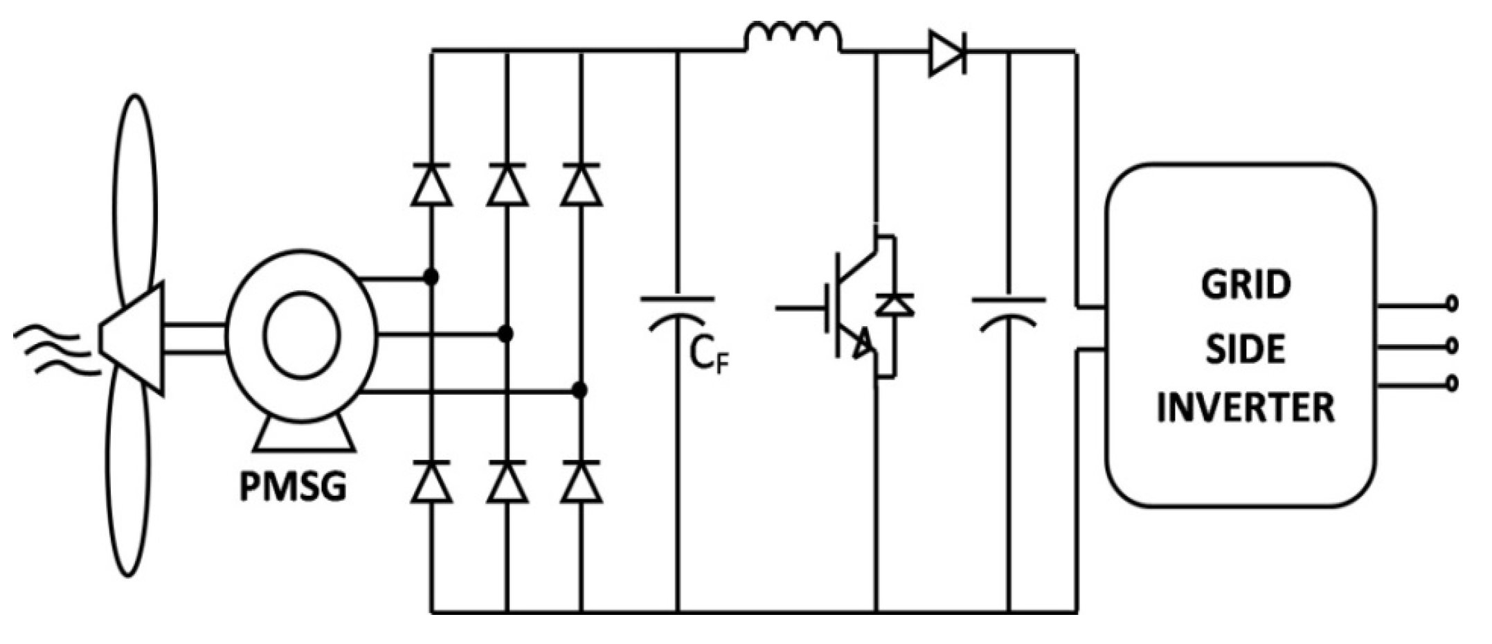
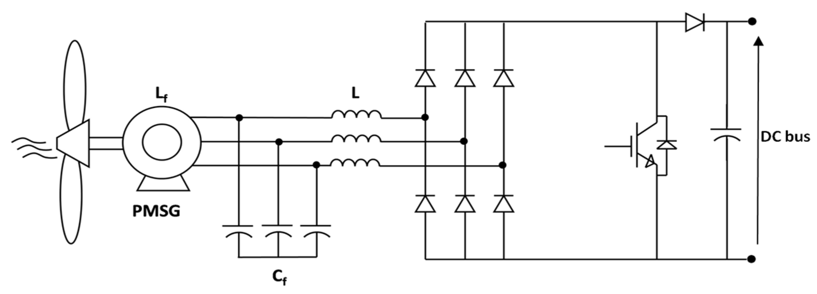
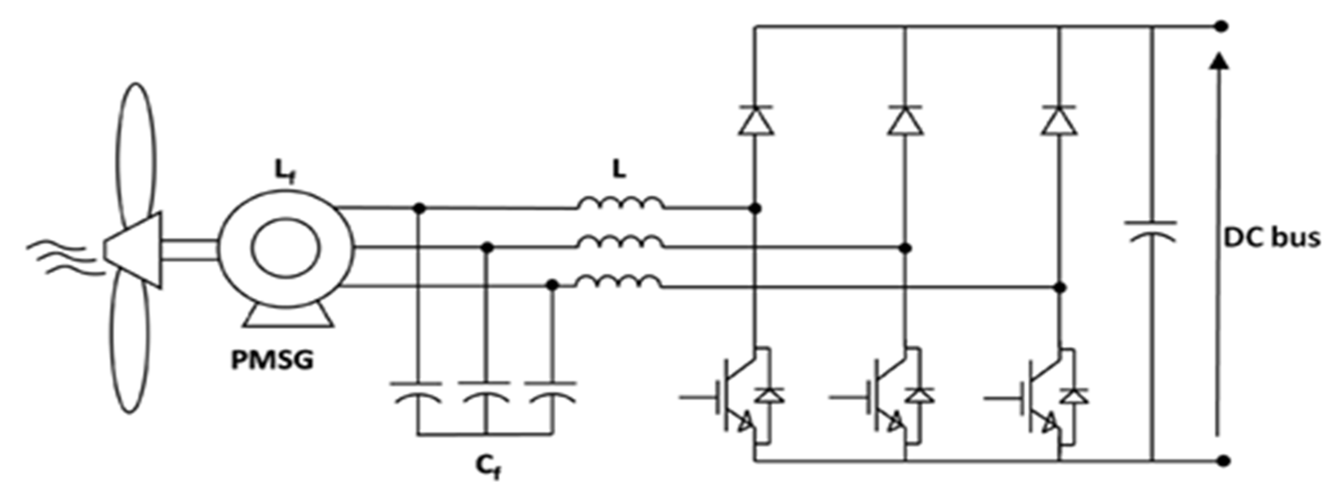
2. Rectifier Converters for Low-Power PMSG


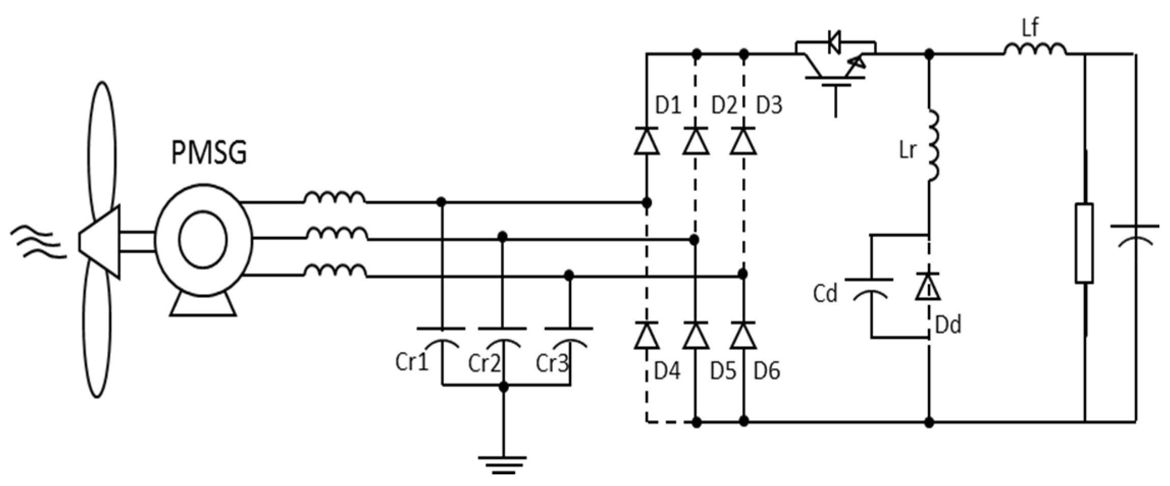
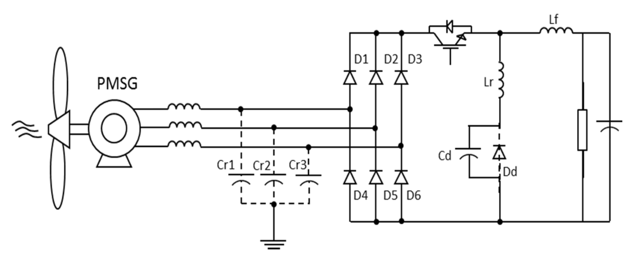
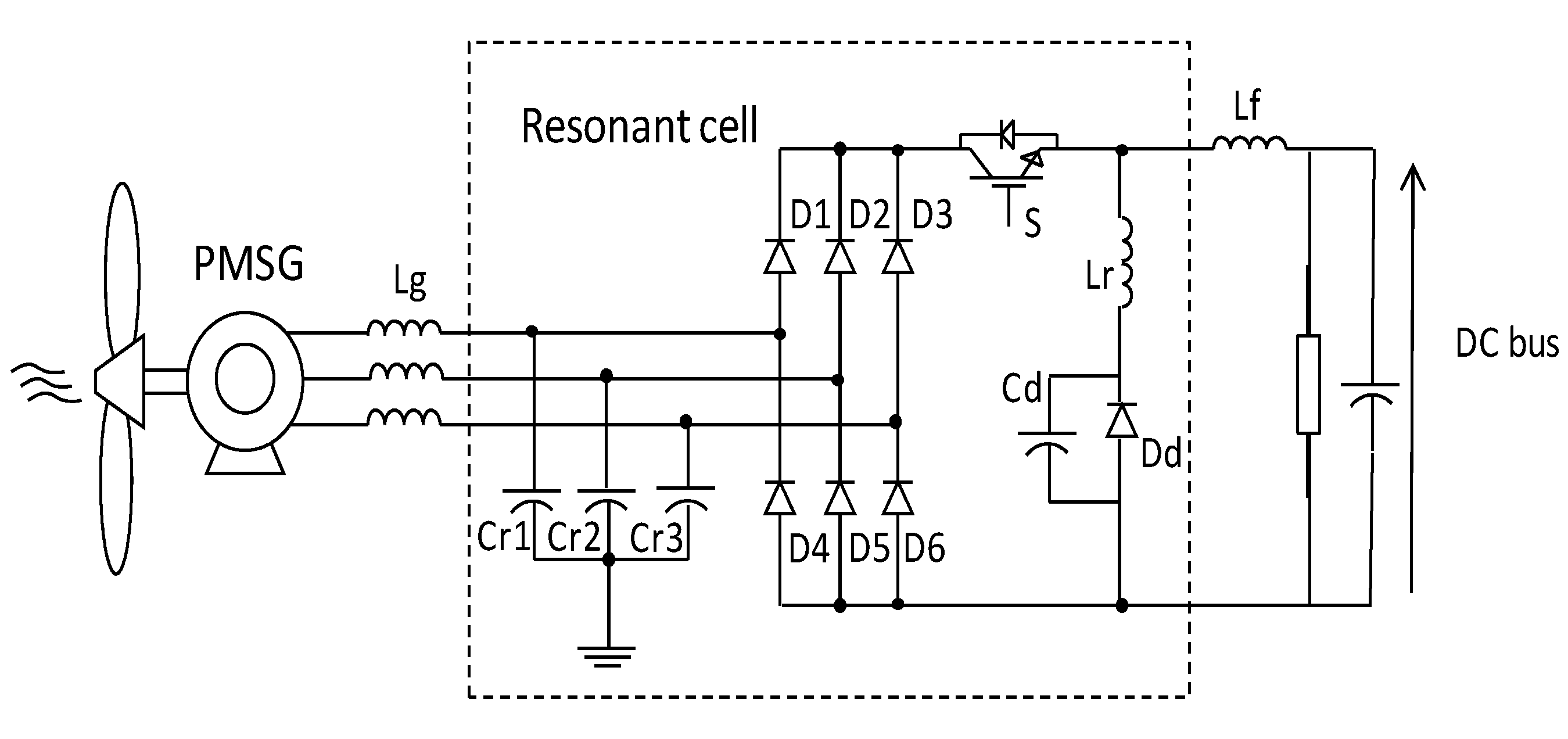
3. The Analyzed Converter

3.1. Multi-Resonant Buck-Converter Operational Steps
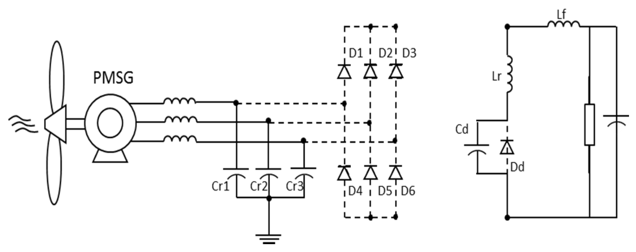
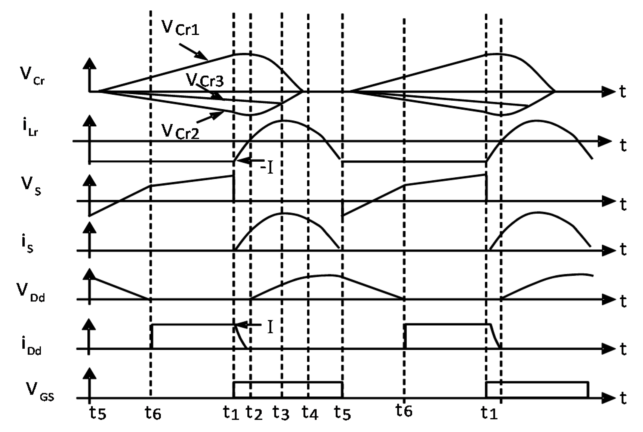
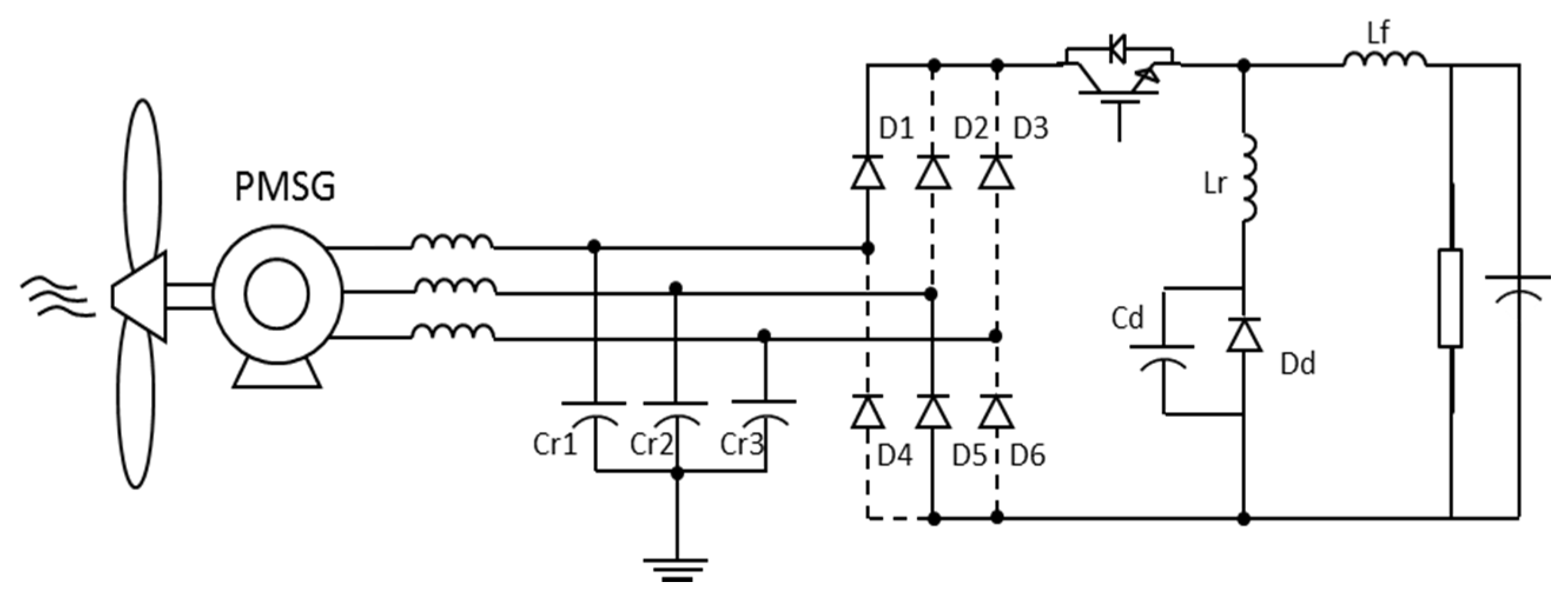
3.1.1. Step 1
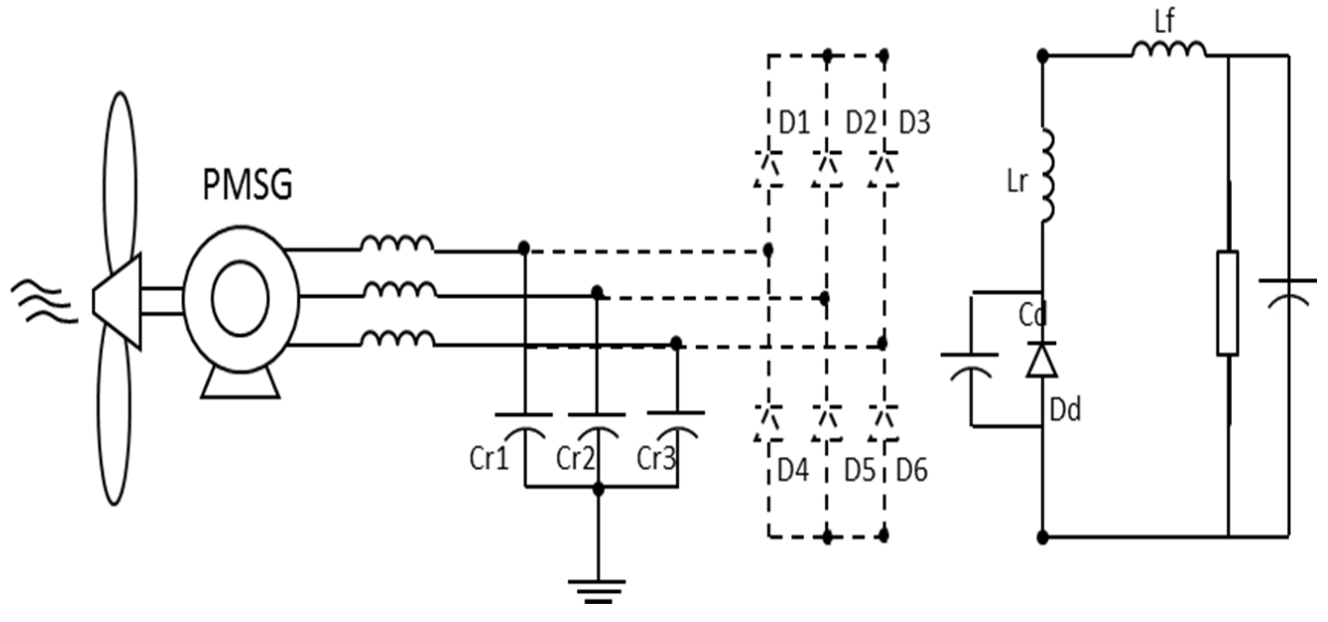
3.1.2. Steps 2 to 5


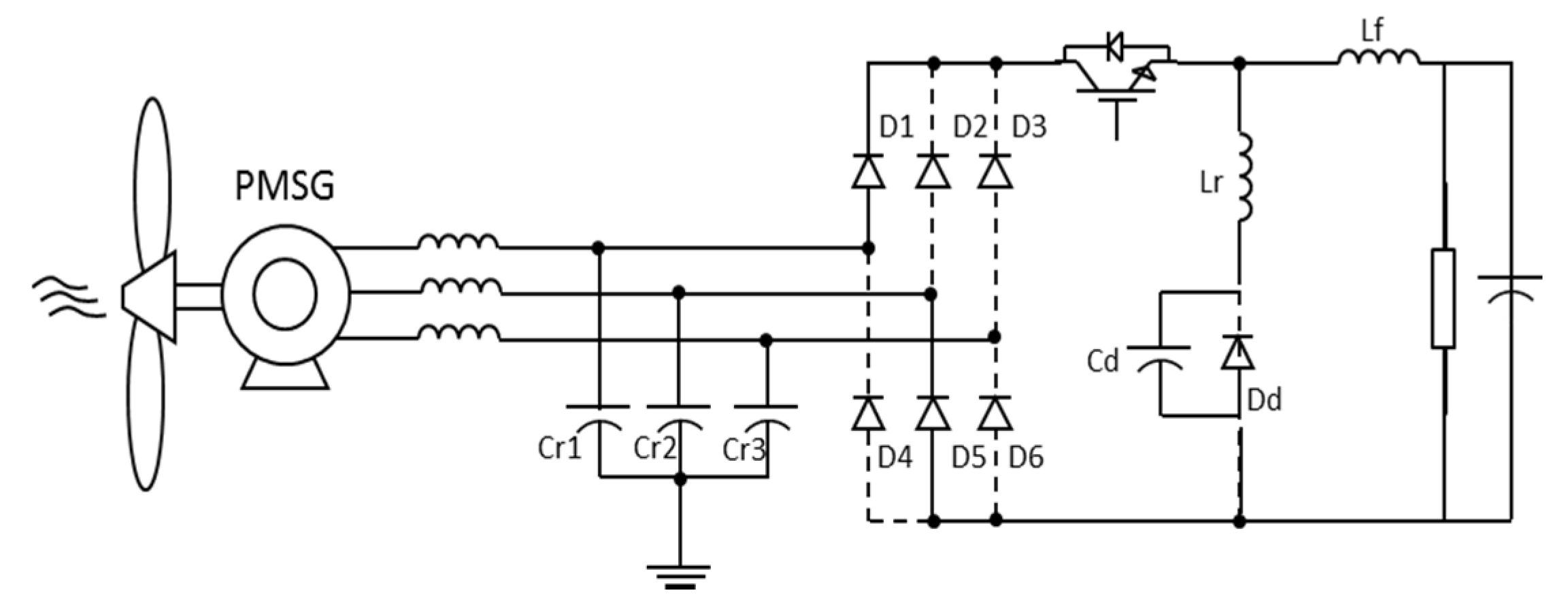
3.1.3. Step 6
3.2. Design Equations
3.3. Sensitive Analysis of Parameters

| Lr | Cd | R0 | f0 | ton |
|---|---|---|---|---|
| +10% | +10% | = | −10% | +10% |
| −10% | −10% | = | +10% | −10% |
| −10% | +10% | ≈−10% | = | ≅ |
| +10% | −10% | ≈+10% | = | = |
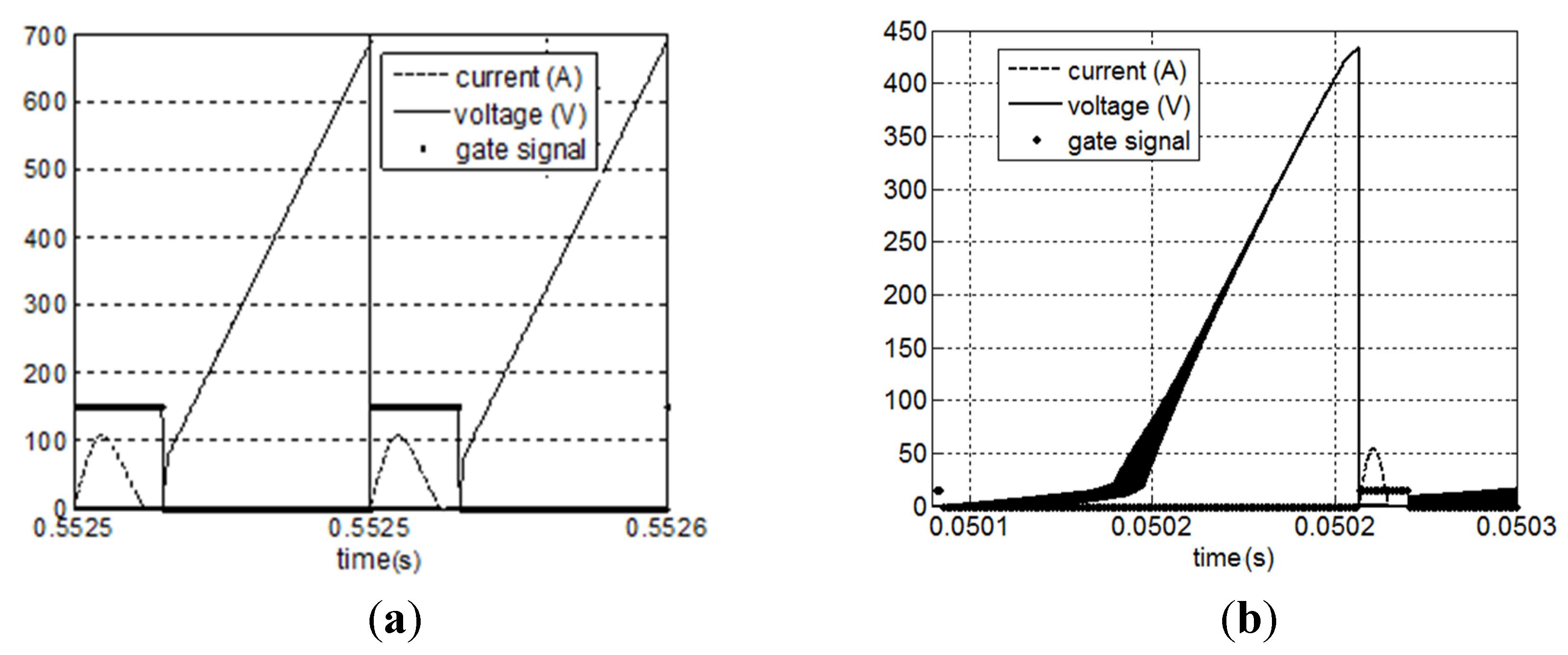
4. Design Example and Simulation Results
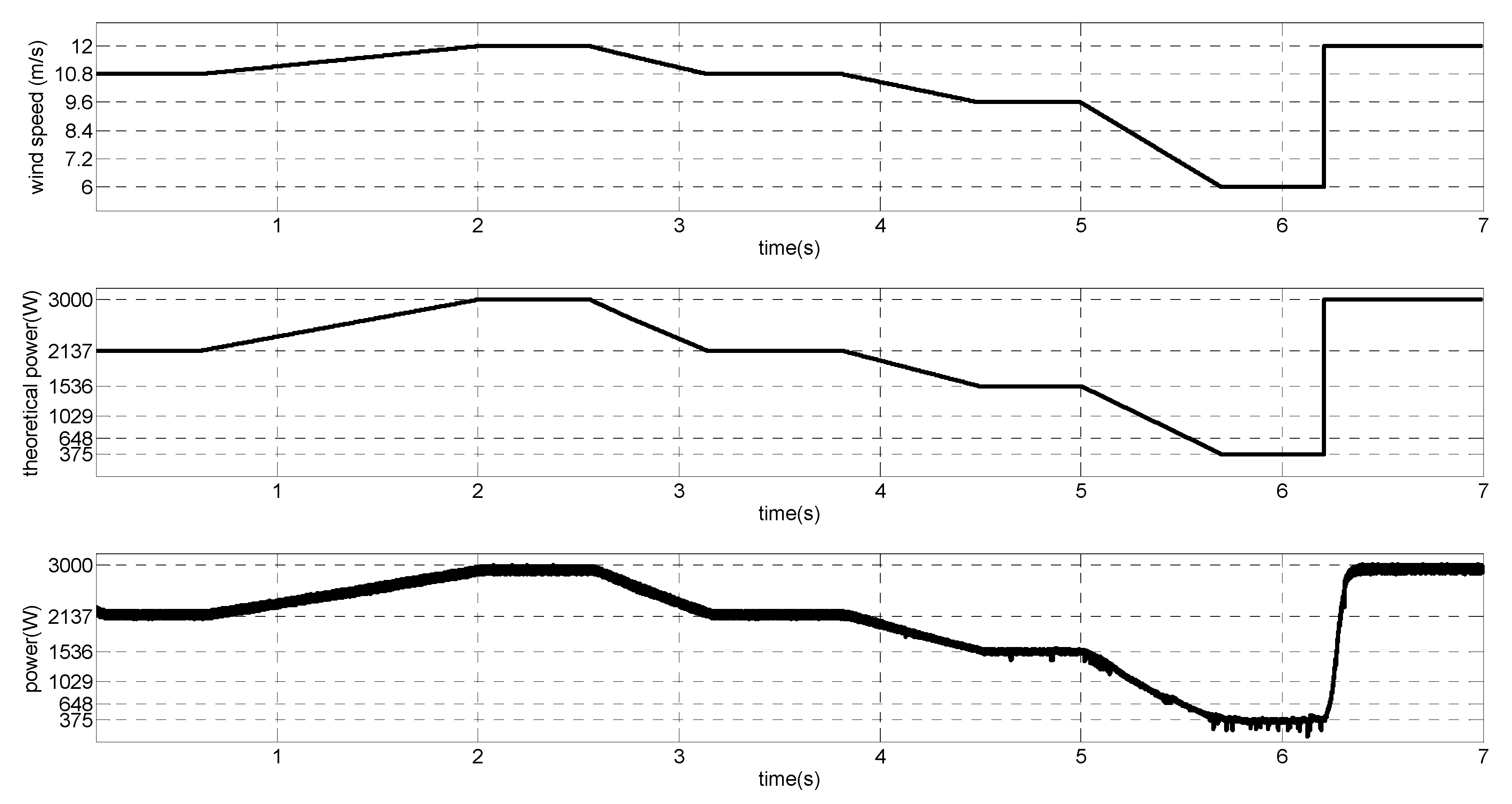
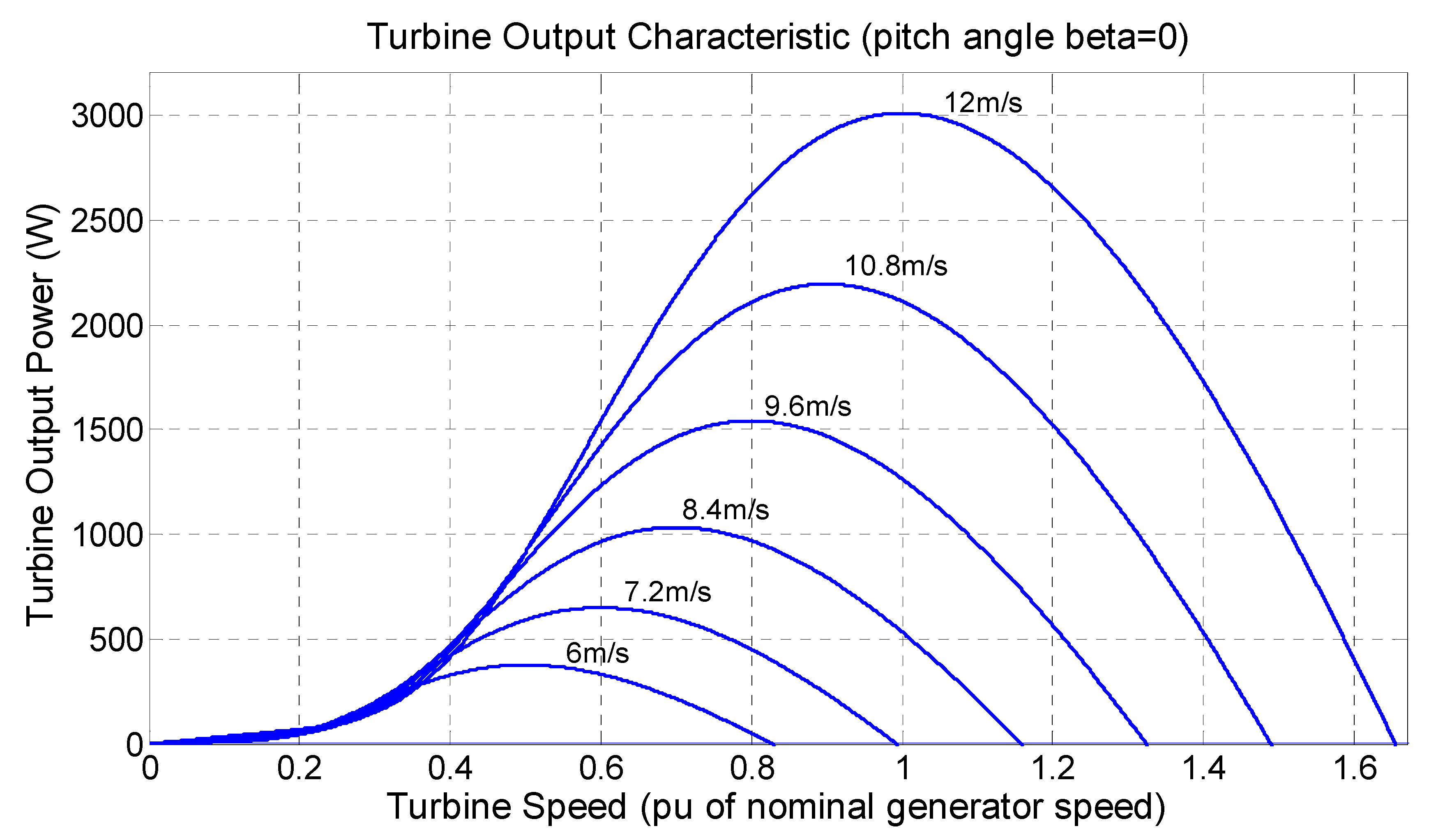
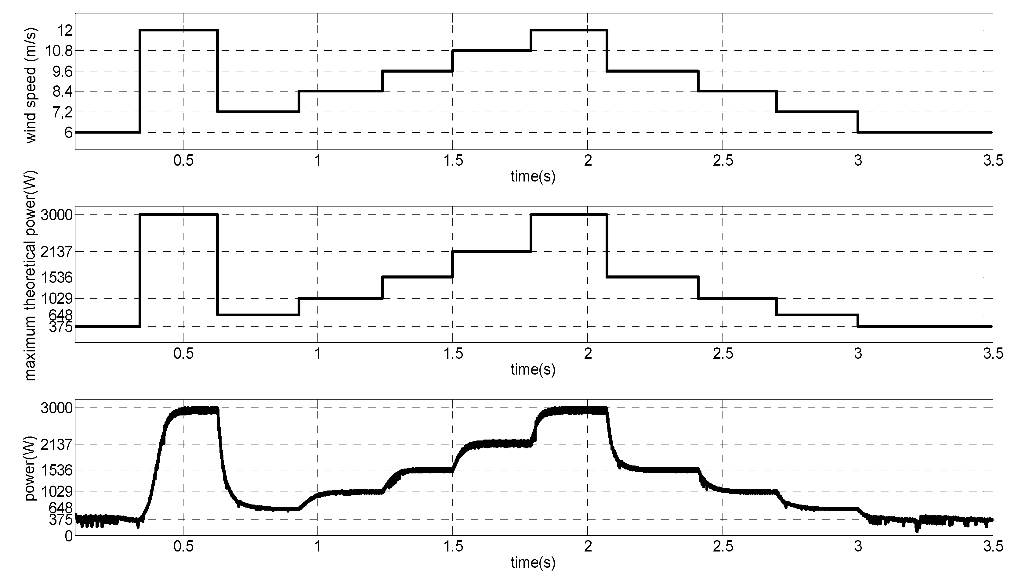
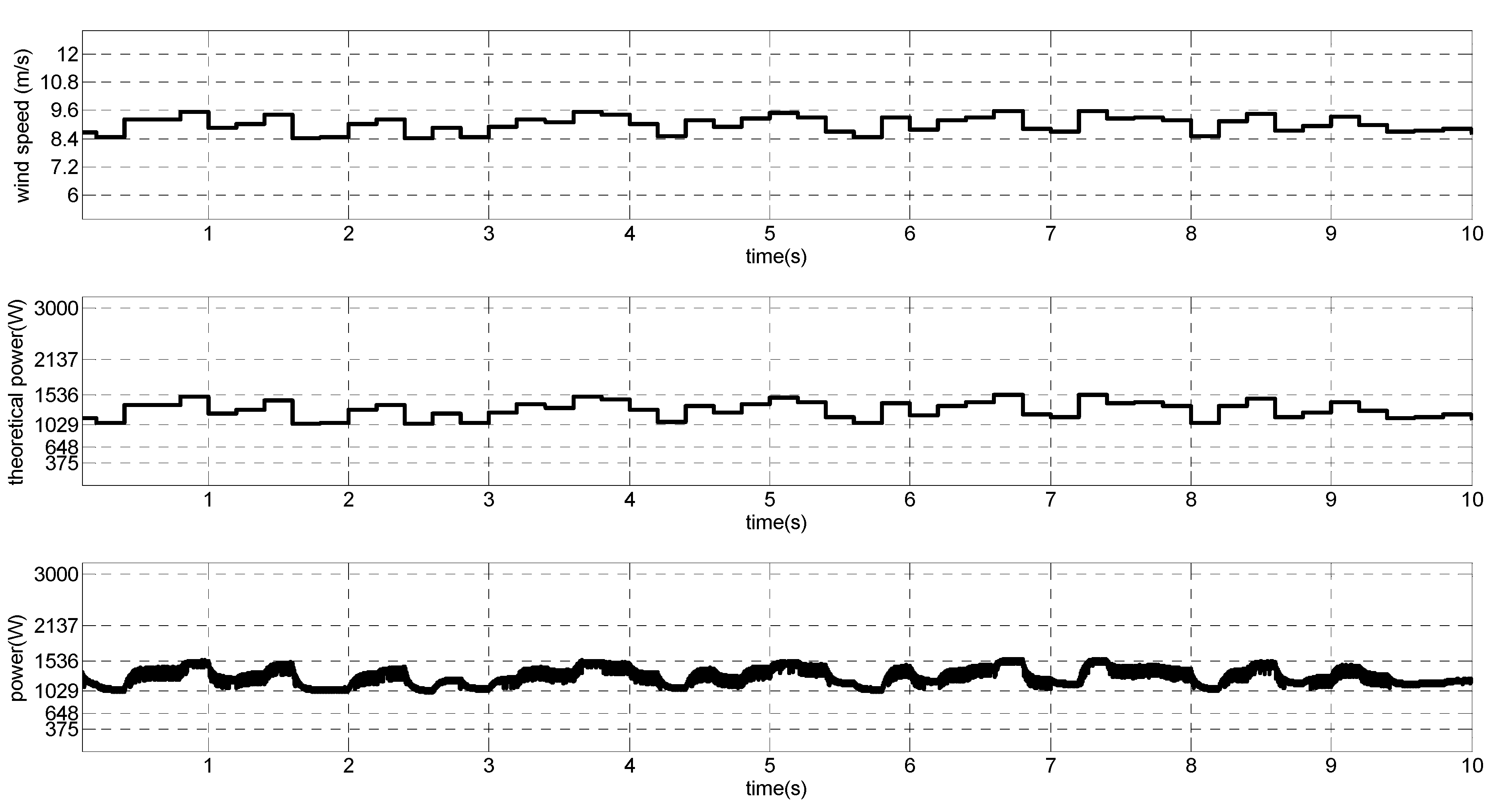
4.1. MPPT Control
4.2. Converter Project
| Prated | Lg | vwind,rated | vwind,cut-in | VLL,rms (40 Hz) | VLL,rms (10 Hz) |
|---|---|---|---|---|---|
| 3 kW | 12 mH | 12 m/s (40 Hz) | 3 m/s (10 Hz) | 220 V | 78 V |
| ton | fo | Lr | Cd | Cr |
|---|---|---|---|---|
| 12 µs | 42 kHz | 20.52 µH | 0.704 µF | 1.056 µF |
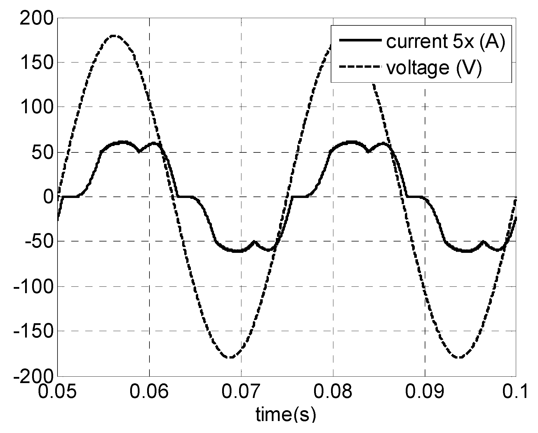
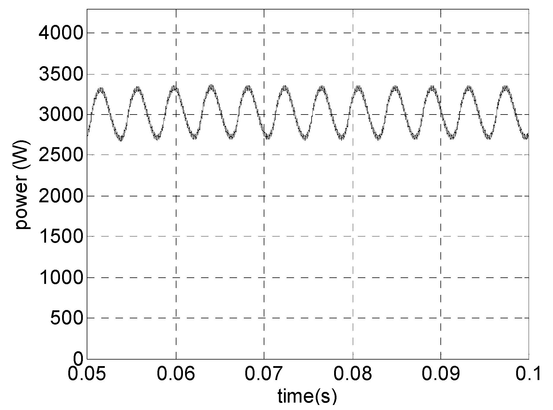
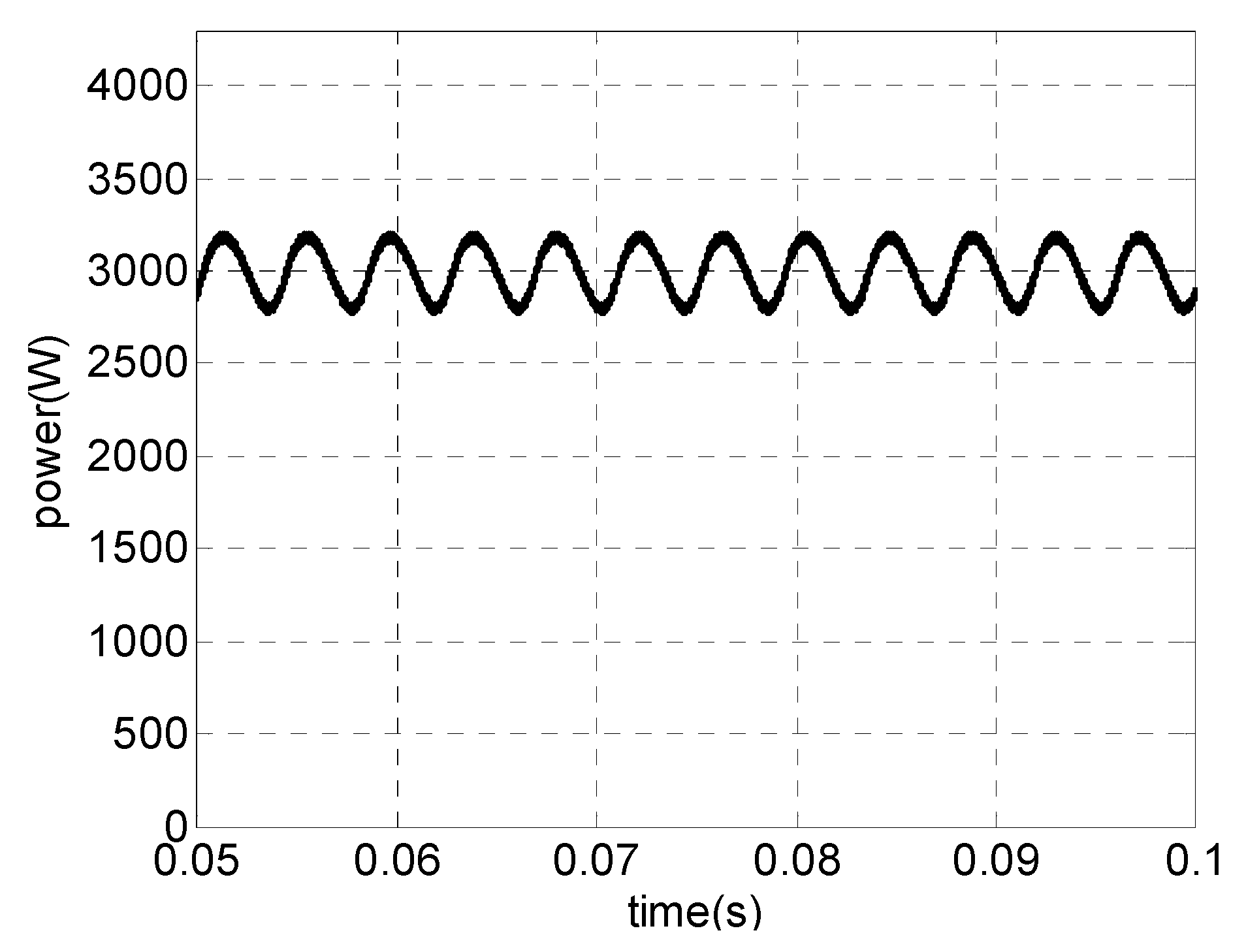
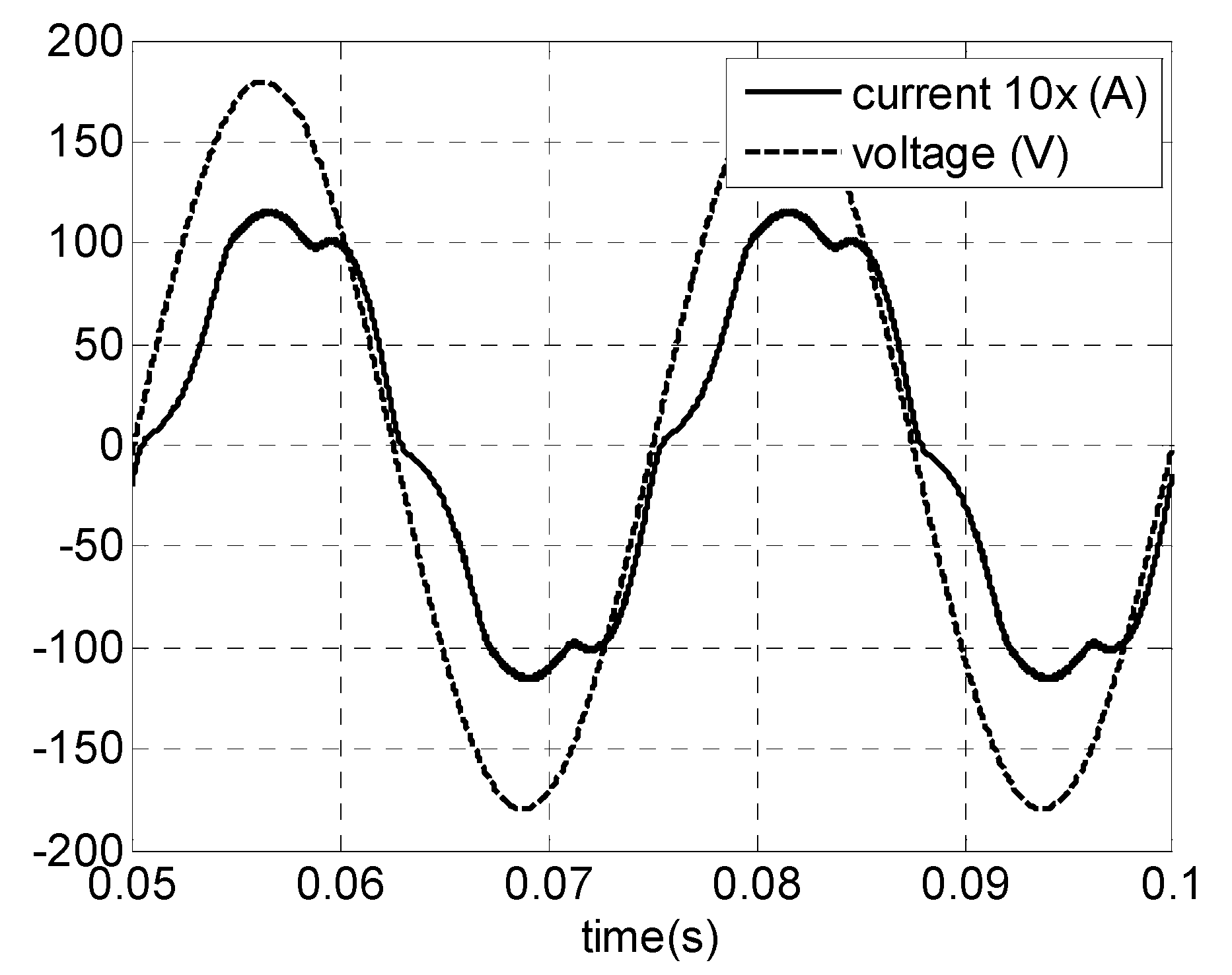
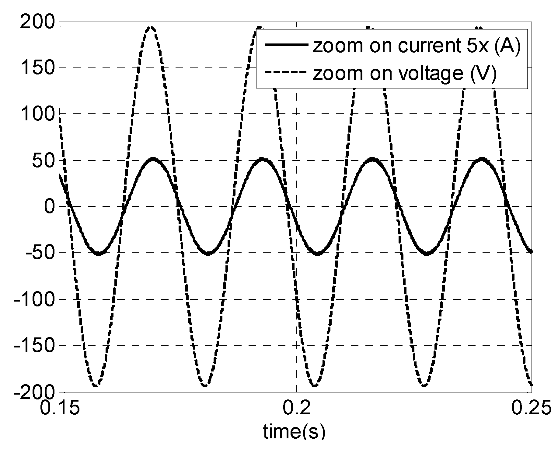
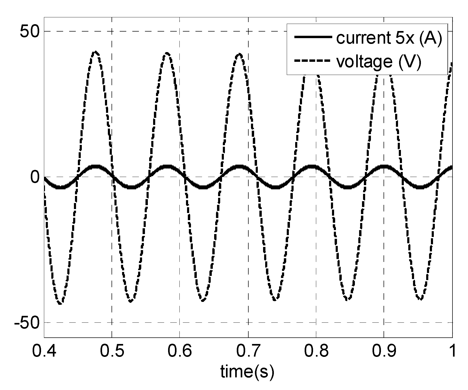
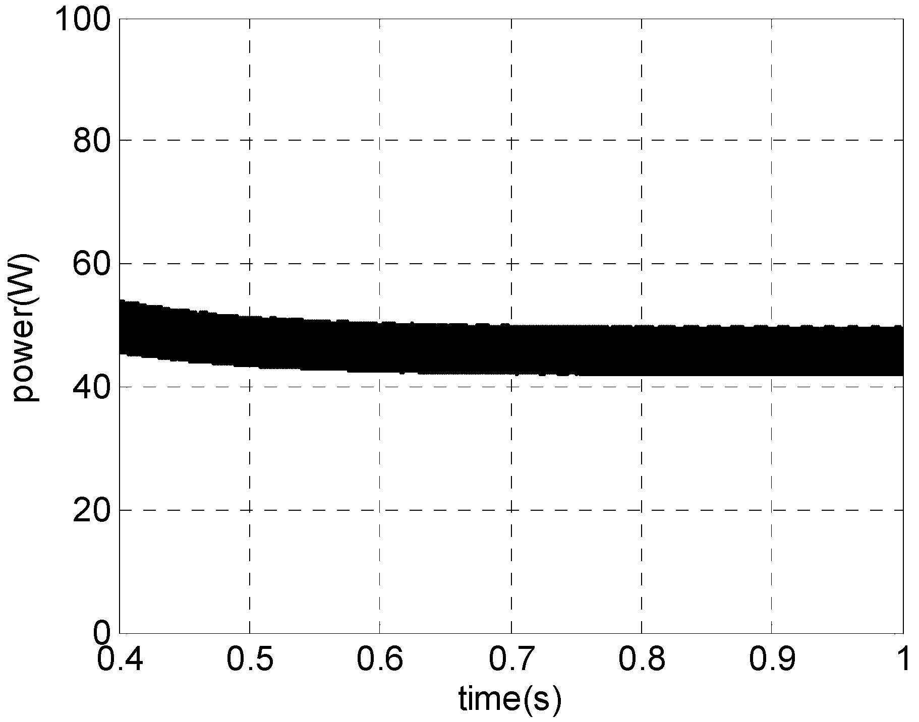
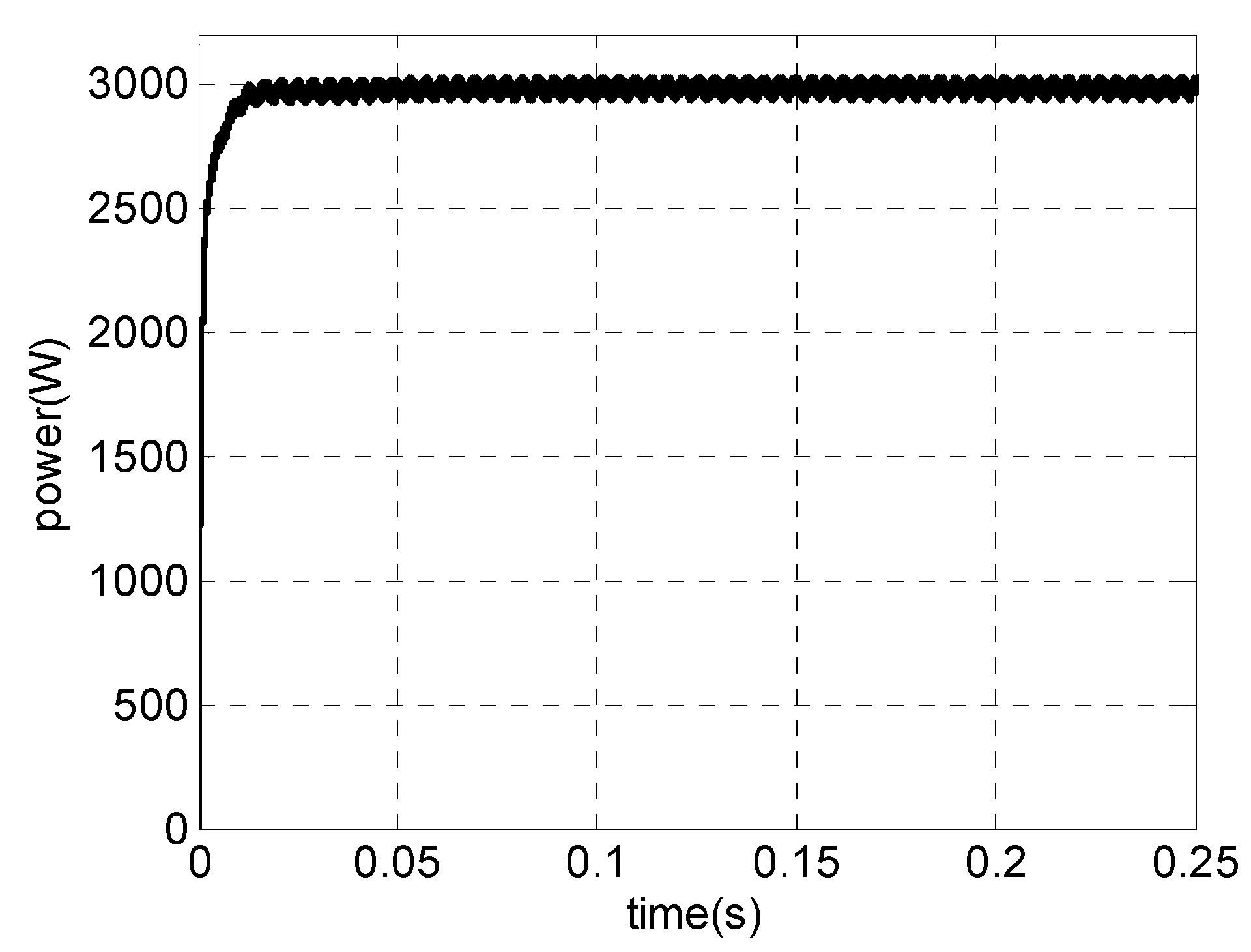
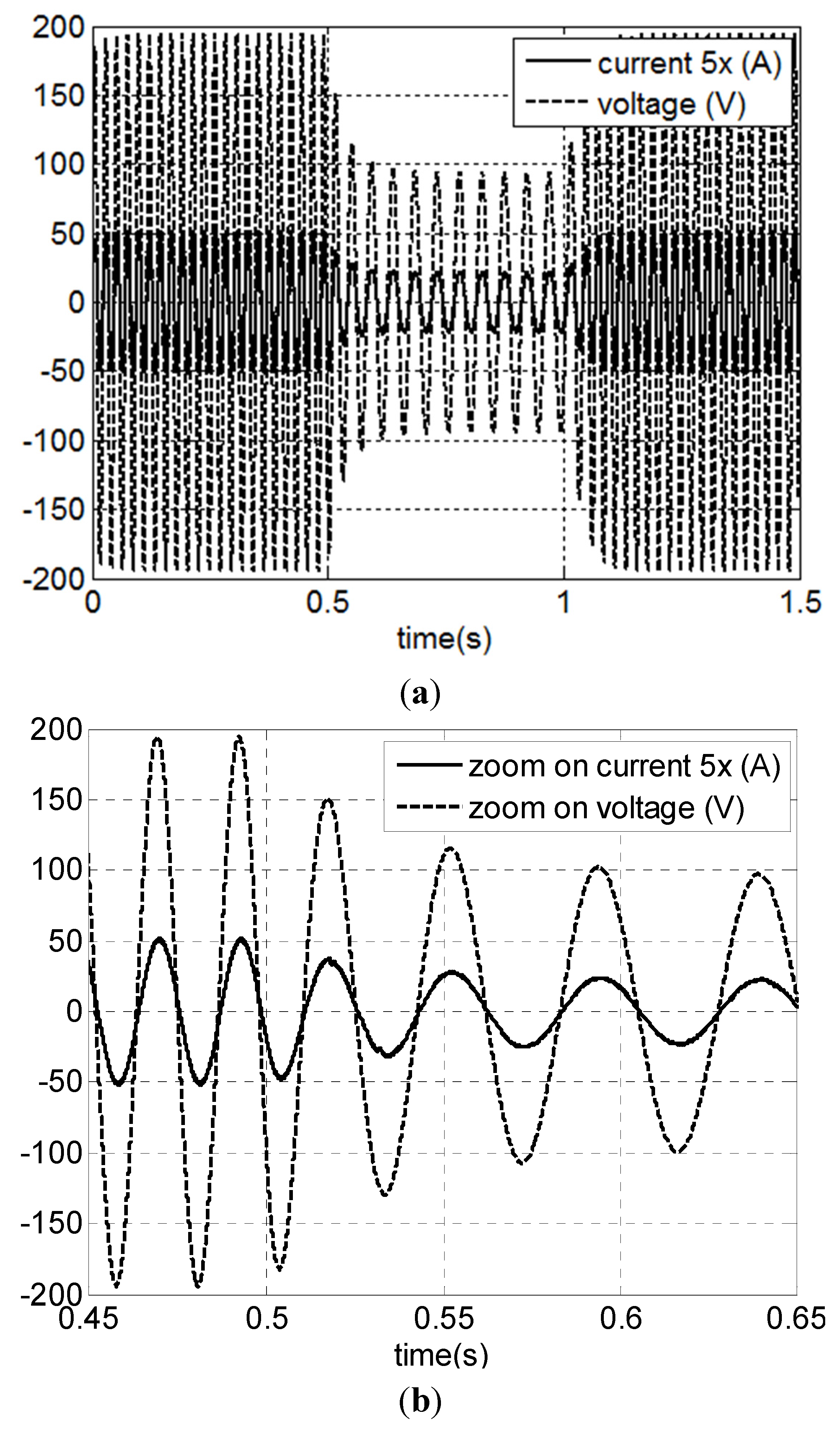
4.3. Simulation Results


5. Conclusions
Acknowledgments
Author Contributions
Conflicts of Interest
References
- Ahmed, N.A.; Miyatake, M. A stand-alone hybrid generation system combining solar photovoltaic and wind turbine with simple maximum power point tracking control. In Proceedings of the CES/IEEE 5th International Power Electronics and Motion Control Conference, Shanghai, China, 14–16 August 2006; pp. 1–7.
- Carrasco, J.M.; Franquelo, L.G.; Bialasiewicz, J.T.; Galvan, E.; Guisado, R.C.P.; Prats, M.A.M.; Leon, J.I.; Moreno-Alfonso, N. Power-electronic systems for the grid integration of renewable energy sources: A survey. IEEE Trans. Ind. Electron. 2006, 53, 1002–1016. [Google Scholar] [CrossRef]
- De Ribeiro, L.A.S.; Saavedra, O.R.; de Matos, J.G.; Lima, S.L.; Bonan, G.; Martins, A.S. Design, control, an operation of a hybrid electrical generation system based on renewable energy sources. Rev. Eletrôn. Potênc. 2010, 15, 313–322. [Google Scholar]
- Tsai, C.-T.; Shen, C.-L.; Su, J.-C. A power supply system with ZVS and current-doubler features for hybrid renewable energy conversion. Energies 2013, 6, 4859–4878. [Google Scholar] [CrossRef]
- Liserre, M.; Sauter, T.; Hung, J.Y. Future energy systems: Integrating renewable energy sources into the smart power grid through industrial electronics. IEEE Ind. Electron. Mag. 2010, 4, 18–37. [Google Scholar] [CrossRef]
- Mahmoud, M.S.; Azher Hussain, S.; Abido, M.A. Modeling and control of micro grid: An overview. J. Frankl. Inst. 2014, 351, 2822–2859. [Google Scholar] [CrossRef]
- Wang, X.; Guerrero, J.M.; Chen, Z.; Blaabjerg, F. Distributed energy resources in grid interactive AC micro grids. In Proceedings of the 2nd IEEE International Symposium on Power Electronice for Distributed Generation Systems (PEDG), Hefei, China, 16–18 June 2010; pp. 806–812.
- Meegahapola, L.G.; Robinson, D.; Agalgaonkar, A.P.; Perera, S.; Ciufo, P. Micro grids of commercial buildings: Strategies to manage mode transfer from grid connected to islanded mode. IEEE Trans. Sustain. Energy 2014, 5, 1337–1347. [Google Scholar] [CrossRef]
- Justo, J.J.; Mwasilu, F.; Lee, J.; Jung, J.W. AC-micro grids versus DC-micro grids with distributed energy resources: A review. Renew. Sustain. Energy Rev. 2013, 24, 387–405. [Google Scholar] [CrossRef]
- Rocabert, J.; Luna, A.; Blaabjerg, F.; Rodríguez, P. Control of power converters in AC micro grids. IEEE Trans. Power Electron. 2012, 27, 4734–4749. [Google Scholar] [CrossRef]
- Liu, X.; Wang, P.; Loh, P.C. A hybrid AC/DC micro grid and its coordination control. IEEE Trans. Smart Grid 2011, 2, 278–286. [Google Scholar]
- Park, S.-H.; Choi, J.-Y.; Won, D.-J. Cooperative control between the distributed energy resources in AC/DC hybrid micro grid. In Proceedings of the Innovative Smart Grid Technologies Conference (ISGT), Washington, DC, USA, 19–22 February 2014; pp. 1–5.
- Dragicevic, T.; Vasquez, J.C.; Guerrero, J.M.; Skrlec, D. Advanced LVDC electrical power architectures and micro grids: A step towards a new generation of power distribution networks. IEEE Electr. Mag. 2014, 2, 54–65. [Google Scholar] [CrossRef]
- Majumder, R. A hybrid micro grid with DC connection at back to back converters. IEEE Trans. Smart Grid 2014, 51, 251–259. [Google Scholar] [CrossRef]
- Hsiao, C.-Y.; Yeh, S.-N.; Hwang, J.-C. Design of high performance permanent-magnet synchronous wind generators. Energies 2014, 7, 7105–7124. [Google Scholar] [CrossRef]
- Oliveira, D.S., Jr.; Reis, M.M.; Silva, C.E.A.; Barreto, L.H.S.C.; Antunes, F.L.M.; Soares, B.L.A. Three-phase high-frequency semi controlled rectifier for PM WECS. IEEE Trans. Power Electron. 2010, 25, 677–685. [Google Scholar] [CrossRef]
- Dos Reis, F.S.; Tan, K.; Islam, S. Using PFC for harmonic mitigation in wind turbine energy conversion systems. In Proceedings of the 30th Annual Conference of IEEE Industrial Electronics Society (IECON 2004), Busan, Korea, 2–6 November 2004; pp. 3100–3105.
- Wang, Y.-F.; Yang, L.; Wang, C.-S.; Li, W.; Qie, W.; Tu, S.-J. High step-up 3-Phase rectifier with fly-back cells and switched capacitors for small-scaled wind generation systems. Energies 2015, 8, 2742–2768. [Google Scholar] [CrossRef]
- Cheng, M.; Zhu, Y. The state of the art of wind energy conversion systems and technologies: A review. Energy Convers. Manag. 2014, 88, 332–347. [Google Scholar] [CrossRef]
- Kazmi, S.M.R.; Goto, H.; Guo, H.; Ichinokura, O. A novel algorithm for fast and efficient speed-sensorless maximum power point tracking in wind energy conversion systems. IEEE Trans. Ind. Electron. 2011, 58, 29–36. [Google Scholar] [CrossRef]
- Ni, B.; Sourkounis, C. Influence of wind-energy-converter control methods on the output frequency components. IEEE Trans. Ind. Appl. 2009, 45, 2116–2122. [Google Scholar]
- Oliveira, D.S.; de Sousa, G.J.M.; Rangel, A.R.; Queiroz, D.L.; de Oliveira, E.F.; dos Santos, L.P.C.; Fontenele, L.F.A.; Bezerra, P.A.M. Low cost and high efficiency static converter for small wind systems. In Proceedings of the 35th Annual Conference of IEEE Industrial Electronics Society (IECON 2009), Porto, Portugal, 3–5 November 2009; pp. 601–608.
- Orlando, N.A.; Liserre, M.; Mastromauro, R.A.; Dell’Aquila, A. A survey of control issues in PMSG-based small wind-turbine systems. IEEE Trans. Ind. Inf. 2013, 9, 1211–1221. [Google Scholar] [CrossRef]
- Vattuone, L.; Kouro, S.; Estay, G.; Wu, B. Open-end-winding PMSG for wind energy conversion system with dual boost NPC converter. In Proceedings of the IEEE International Conference on Industrial Technology (ICIT), Cape Town, South Africa, 25–28 February 2013; pp. 1763–1768.
- Zhang, S.; Tseng, K.-J.; Vilathgamuwa, D.M.; Nguyen, T.D.; Wang, X.-Y. Design of a robust grid interface system for PMSG-based wind turbine generators. IEEE Trans. Ind. Electron. 2011, 58, 316–328. [Google Scholar] [CrossRef]
- Ahmed, A.; Ran, L.; Bumby, J.R. New constant electrical power soft-stalling control for small-scale VAWTs. IEEE Trans. Energy Convers. 2010, 25, 1152–1161. [Google Scholar] [CrossRef]
- Carranza, O.; Figueres, E.; Garcerá, G.; González, L.G. A control circuit small wind turbines with low harmonic distortion and improved power factor. In Proceedings of the International Conference on Renewable Energies and Power Quality—ICREPQ, Valencia, Spain, 15–17 April 2009.
- Tonkoski, R.; Lopes, L.A.C.; dos Reis, F.S. A single-switch three-phase boost rectifier to reduce the generator losses in wind energy conversion systems. In Proceedings of the IEEE Electrical Power & Energy Conference, Montreal, QC, Canada, 22–23 October 2009; pp. 1–8.
- Reis, M.M.; Soares, B.; Barreto, L.H.S.C.; Freitas, E.; Silva, C.E.A.; Bascope, R.T.; Oliveira, D.S. A variable speed wind energy conversion system connected to the grid for small wind generator. In Proceedings of the 23rd Annual IEEE Applied Power Electronics Conference and Exposition, Austin, TX, USA, 24–28 February 2008; pp. 751–755.
- Juan, Y.-L. An integrated-controlled AC/DC interface for microscale wind power generation systems. IEEE Trans. Power Electron. 2011, 26, 1377–1384. [Google Scholar] [CrossRef]
- Liu, K.H.; Lin, Y.L. Current waveform distortion in power factor correction circuits employing discontinuous mode boost converter. In Proceedings of the 20th Annual IEEE Power Electronics Specialists Conference, Milwaukee, WI, USA, 26–29 June 1989; pp. 825–829.
- Faulstich, A.; Stinke, J.K.; Wittwer, F. Medium voltage converter for permanent magnet wind power generators up to 5 MW. In Proceedings of the European Conference Power Electronics Applications, Dresden, Germany, 11–14 September 2005; pp. 1–9.
- Freitas, T.R.S. Alternativas de Topologias Retificadoras para Geração Eólica com Geradores Síncronos a Ímã Permanente de Baixa Potência. Doctoral Thesis, Qualification Exam, Federal University of Espírito Santo, Espírito Santo, Brazil, 2014. [Google Scholar]
- Jang, Y.; Erickson, R.W. New Single-Switch Three-Phase High-Power-Factor Rectifiers Using Multiresonant Zero-current Switching. IEEE Trans. Power Electron. 1998, 13, 194–201. [Google Scholar] [CrossRef]
- Ismail, E.H.; Erickson, R.W. A single transistor three-phase resonant switch for high quality rectification. In Proceedings of the 23rd Annual IEEE Power Electronics Specialists Conference, Toledo, Spain, 29 June–3 July 1992; pp. 1341–1351.
- Jang, Y.; Jovanovic, M.M. Design considerations and performance evaluation of a 6-kW, single-switch, three-phase, high-power-factor, multi-resonant, zero-current-switching buck rectifier. In Proceedings of the 19th International IEEE Telecommunications Energy Conference, Melbourne, Australia, 22–23 October 1997; pp. 715–722.
- Kazmi, S.M.R.; Goto, H.; Guo, H.-J.; Ichinokura, O. Review and critical analysis of the research papers published till date on maximum power point tracking in wind energy conversion system. In Proceedings of the IEEE Energy Conversion Congress and Exposition (ECCE), Atlanta, GA, USA, 12–16 September 2010; pp. 4075–4082.
- Abdullah, M.A.; Yatim, A.H.M.; Tan, C.W. A study of maximum power point tracking algorithms for wind energy system. In Proceedings of the IEEE First Conference on Clean Energy and Technology (CET), Kuala Lumpur, Malasian, 27–29 June 2011; pp. 321–326.
- Dixit, A.; Singh, P.; Mishra, N.; Singh, D. Maximum power tracking with voltage stability studies in wind energy conversion system: A review. In Proceedings of the IET Chennai 3rd International on Sustainable Energy and Intelligent Systems, Tiruchengode, India, 27–29 December 2012; pp. 1–9.
- Simeonov, G. Resonant Boost Converter for Distributed Maximum Power Point Tracking in Grid-Connected Photovoltaic Systems. Master Thesis, University of Toronto, Toronto, ON, Canada, 2010. [Google Scholar]
© 2015 by the authors; licensee MDPI, Basel, Switzerland. This article is an open access article distributed under the terms and conditions of the Creative Commons Attribution license (http://creativecommons.org/licenses/by/4.0/).
Share and Cite
Freitas, T.; Menegáz, P.; Simonetti, D. A New Application of the Multi-Resonant Zero-Current Switching Buck Converter: Analysis and Simulation in a PMSG Based WECS. Energies 2015, 8, 10219-10238. https://doi.org/10.3390/en80910219
Freitas T, Menegáz P, Simonetti D. A New Application of the Multi-Resonant Zero-Current Switching Buck Converter: Analysis and Simulation in a PMSG Based WECS. Energies. 2015; 8(9):10219-10238. https://doi.org/10.3390/en80910219
Chicago/Turabian StyleFreitas, Tiara, Paulo Menegáz, and Domingos Simonetti. 2015. "A New Application of the Multi-Resonant Zero-Current Switching Buck Converter: Analysis and Simulation in a PMSG Based WECS" Energies 8, no. 9: 10219-10238. https://doi.org/10.3390/en80910219
APA StyleFreitas, T., Menegáz, P., & Simonetti, D. (2015). A New Application of the Multi-Resonant Zero-Current Switching Buck Converter: Analysis and Simulation in a PMSG Based WECS. Energies, 8(9), 10219-10238. https://doi.org/10.3390/en80910219