Article

Effective Local-Global Upscaling of Fractured Reservoirs under Discrete Fractured Discretization

1
Department of Energy & Resources Engineering, College of Engineering, Peking University, Beijing 100871, China
2
Research Institute of Petroleum Exploration and Development, PetroChina, Beijing 100083, China
3
Department of Chemical & Biomolecular Engineering, University of Houston, Houston, TX 77004, USA
*
Author to whom correspondence should be addressed.
Energies 2015, 8(9), 10178-10197; https://doi.org/10.3390/en80910178
Submission received: 3 April 2015 / Revised: 17 August 2015 / Accepted: 10 September 2015 / Published: 17 September 2015

Abstract

:
The subsurface flow in fractured reservoirs is strongly affected by the distribution of fracture networks. Discrete fracture models, which represent all fractures individually by unstructured grid systems, are thus developed and act as a more accurate way for fractured reservoir simulation. However, it is usually not realistic to directly apply discrete fracture models to simulate field scale models for efficiency reasons. There is a need for upscaling techniques to coarsen the high resolution fracture descriptions to sizes that can be accommodated by reservoir simulators. In this paper, we extended the adaptive local-global upscaling technique to construct a transmissibility-based dual-porosity dual-permeability model from discrete fracture characterizations. An underlying unstructured fine-scale grid is firstly generated as a base grid. A global coarse-scale simulation is performed to provide boundary conditions for local regions and local upscaling procedures are carried out in every local region for transmissibility calculations. Iterations are performed until the consistency between the global and local properties is achieved. The procedure is applied to provide dual-porosity dual-permeability (DPDK) parameters including coarse-scale matrix-matrix, fracture-fracture and matrix-fracture flux transmissibilities. The methodology is applied to several cases. The simulation results demonstrate the accuracy, efficiency and robustness of the proposed method.

1. Introduction

Modeling of fluid flow through fractured porous reservoirs is very complicated due to the extremely high heterogeneity in geometry scale and permeability between the matrix and fracture media. Accurate and efficient simulation of such systems remains a challenge. Recently many technical improvements are achieved to enable more reliable fracture predictions in the form of discrete fracture representations. These models, however, are generally too detailed for direct use in reservoir simulation, especially when many simulation runs are required to address the geological uncertainty. It is necessary to develop methods that can provide accurate and efficient flow models from high-resolution fracture characterizations.
The dual-porosity (DP) model was first proposed by Barenblatt and Zheltov [1] and introduced to the petroleum industry by Warren and Root [2]. In DP models, the fractured reservoir is represented by the matrix and fracture media, which are overlapping spatially. The matrix medium acts as a source of reserves while the fracture medium is assumed as the channel through which large-scale flow occurs. The fluid interaction between these two continua is represented by a transfer function called shape factor. Dual-porosity dual-permeability (DPDK) models, which consider matrix-matrix fluxes besides fracture-fracture fluxes, were introduced when flow through matrix medium is not negligible.
Although very efficient and to some extent capable for capturing the flow behavior of fractured reservoirs, the DP models suffer from some limitations due to its idealized representation of the actual geological description. For example, the complex flow behavior between fracture and matrix medium is represented by the shape factor as a function of fracture spacing only [2,3,4]. Although a lot of research [5,6,7,8] aiming to obtain a more accurate shape factor under specific flow scenarios were carried out in those years, most of them were still based on idealized fracture distributions. Another drawback of DP models is they are not well suited for the modeling of a small number of large-scale fractures, which may dominate the flow. For these reasons, discrete-fracture models (DFMs), in which the fractures are represented explicitly, are beginning to find applications in reservoir simulation.
With a fully resolved fracture characterization, DFMs can naturally capture the complex flow phenomena that occur in fractured reservoirs. In order to accommodate the fracture geometry, unstructured grids are usually used in DFMs. Under the unstructured discretization scheme, Baca et al. [9] proposed a 2-D finite-element model for single-phase flow with heat and solute transport. Juanes et al. [10] presented a general finite-element formulation for 2-D and 3-D single-phase flow in fractured porous media. Kim and Deo [11] and Karimi-Fard and Firoozabadi [12] extended the work of Baca et al. for two-phase flow. Karimi-Fard et al. [13] proposed a general and flexible control volume approach to construct connectivities of all control volumes in both 2-D and 3-D fractured models. In a series of works [14,15,16], Hoteit and Firoozabadi proposed a numerical model combined mixed finite element (MFE) method and discontinuous Galerkin (DG) method to handle saturation discontinuity caused by capillary heterogeneity. In addition, by using a hybrid time scheme and without the use of the cross-flow equilibrium between the fractures and the adjacent matrix blocks, the MFE-DG method allows relatively large time steps and large matrix grid cells next to the fractures.
In recent years, DFM approaches have gained much wider applications due to the improvements in fracture prediction and computer technologies. However the field scale studies with DFMs are still not practical because geologically realistic DFMs remain prohibitively time-consuming, especially for probabilistic studies [17]. In addition, the unstructured gridding could be a very tough issue when a large number of fractures in random distribution are present.
Upscaling techniques are developed to coarsen models that are difficult for direct simulation [18,19]. In terms of the target parameters to be upscaled, those techniques can be classified into single-phase upscaling and multi-phase upscaling. For single-phase upscaling, the only parameters to be upscaled are porosity and the transmissibility (or absolute permeability); while in multi-phase upscaling, multi-phase flow parameters like relative permeability and capillary pressure can be upscaled too. It is generally recognized that, in many cases, it is possible to develop reasonably accurate coarse-scale models for two-phase flow with only the absolute permeability or transmissibility upscaled, particularly when accurate upscaling is used in conjunction with flow-based grid generation. In this paper, we only focus on transmissibility upscaling. It is important to note that, however, multi-phase upscaling will be required when high degrees of coarsening are applied, especially when relative permeability and capillary pressure heterogeneity exist. Compared to the relative permeability upscaling, in addition, effective capillary pressure upscaling technique is paid much less attention on and there is still lack of a sound capillary pressure averaging technique [20,21,22].
Among those upscaling methods, some techniques that entail combinations and variations of DFM and DPDK modeling ideas have been proposed to date. The research was first carried out by Dershowitz et al. [23] and Sarda et al. [24] and extended by others later [25,26]. Karimi-Fard et al. [27] and Gong et al. [28] developed a flow-based upscaling technique, which is referred to as the multiple subregion (MSR) method to construct dual-porosity models from detailed fracture characterizations. This method implements a flow-based division of subgrids and calculates the transmissibilities between each connected coarse blocks based on the discrete fracture network. The MSR method was later applied into multiple geologically realistic DFMs by Hui et al. [17]. The MSR method brings in the link between fine-scale fracture models and coarse dual-porosity/multi-porosity models. However, the determination of the flow scenarios and boundary condition remains an ambiguous issue. For example, in former works of Karimi-Fard et al. [27] and Gong et al. [28], the procedure was carried out in a local upscaling scheme that may result in a large deviation in heterogeneous media. Global upscaling scheme is more widely adopted in other upscaling procedures. However, the global upscaling scheme may be very computationally expensive for large models and therefore hardly be used in real field applications. For example, to solve a simple steady-state pressure field of 10 million grids in global fine-scale with algebraic multigrid (AMG) linear solver will cost at least 8 GB memories which are hardly affordable for most personal computers. In addition, there are always some negative transmissibilities that need special treatment.
Chen and Durlofsky [29,30,31,32] introduced an adaptive local-global (ALG) iterative upscaling technique to account for global flow effects without global fine-scale solutions. The main idea is to use a global coarse-scale pressure solution to determine boundary conditions of local fine-scale regions for computation of upscaled quantities. Using these quantities, another coarse-scale solution may be computed, and the process is repeated until the computed quantities are self-consistent. Near-well effects are incorporated directly into the coarse-scale description. Compared to existing pure local upscaling methods, the technique causes only a modest raise of computational cost but can significantly improve the accuracy of the coarse simulation results. However, the technique was only designed for Cartesian grids and applied in 2-D reservoirs without fractures.
In this paper, we extend the single-phase local-global upscaling approach to handle discrete fractured models based on unstructured grids to construct coarse-scale DPDK models. The fine-scale discrete fractured models are performed under a finite volume scheme. The technique is designed to handle both 2-D and 3-D discrete fracture models based on unstructured grids. This method is applied in several fractured reservoir models. Results demonstrate that the technique is capable of generating highly accurate coarse models from fully-resolved DFMs.

2. Methodology

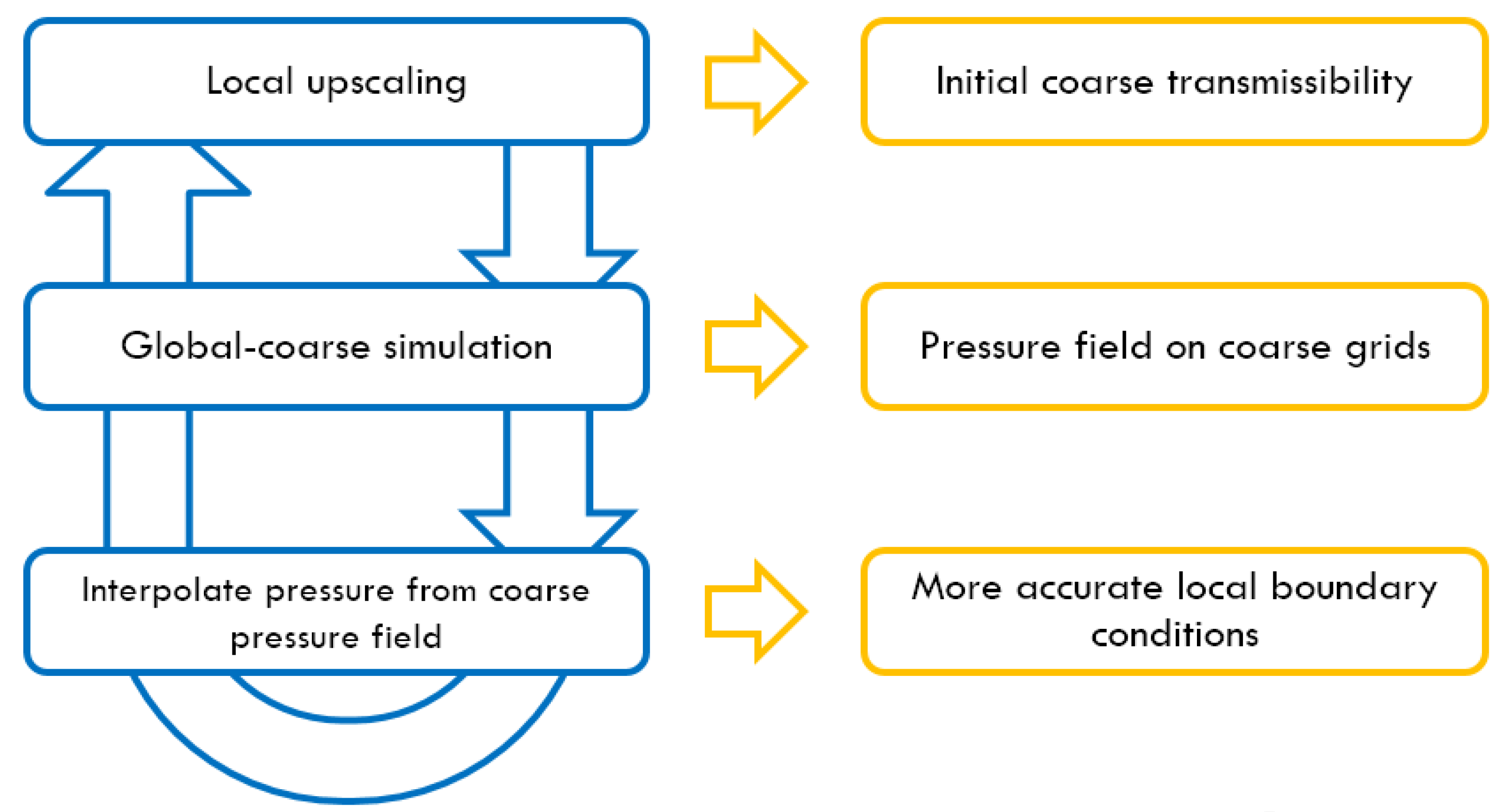
The workflow of the proposed method is shown in Figure 1: (1) A standard extended local upscaling procedure is performed at first and the initial set of DPDK transmissibilities of coarse grids is obtained; (2) Using the initial transmissibilities, a single phase steady-state flow is simulated to generate a preliminary pressure field of the global coarse-scale model; (3) An interpolation technique is applied to construct a series of boundary conditions for each extended local region; (4) Extended local upscaling procedures are performed again with the boundary condition updated in previous step to gain a new set of coarse grid transmissibilities; (5) Repeat the procedures until differences of flow rates or pressures between two iterations get small enough, and a list of transmissibilities of the coarse-scale DPDK model is finally determined.
Figure 1. Workflow of local-global upscaling technique.
Energies 08 10178 g001

2.1. Fine-Coarse-Scale Grids Preparation

An unstructured grid fully conforming to the geometry constrains of the fracture networks is generated using Triangle [33]/TetGen [34] program. Based on this unstructured mesh, the fine-scale discrete fracture model is thus characterized through cell volume, porosity, permeability and depth information and a connection list of the control volumes. The corresponding transmissibility of each connected control volume pair is calculated following the technique by Karimi-Fard et al. [13]. For two-point flux approximations as applied in this study, the flow between two adjacent control volumes is proportional to the pressure difference between them and is written as Equation (1):
Q l , i j = T i j ρ l λ l ( P l , i P l , j )
Here, l denotes the phase; ρ l is the density of phase l ; P i and P j are the pressures associated to cells i and j , and T i j is the transmissibility, which depends on the geometry of the control volumes and the permeability of the system.
The fine-scale DFM grids act as the geometry foundation of the entire upscaling workflow. The extensions and boundary grids of each local region are computed after the coarse model is determined. Then, the fine-scale connection list is applied in the upscaling computations in extended local regions to obtain transmissibilities of the coarse model. In addition, the fine-scale model provides the reference solutions used to validate the upscaled model.
Equations (2) and (3) are used to calculate volume and porosity for the coarse simulation block I respectively:
v b , I c = v m , I c = v f , I c = i = 1 N m v m , i f + i = 1 N f v f , i f
ϕ M , I c = i = 1 N m v m , i f ϕ M , i f v M , I c
where v b , I c , v m , I c and v f , I c are the total volume, matrix volume and fracture volume of coarse block I , respectively; N m and N f are fine matrix grid number and fine fracture grid number in the block I ; v m , i f and v f , i f are the fine grid volume and fine fracture grid volume which index is i ; M denotes the matrix ( m )/fracture medium ( f ); ϕ M , I f is the porosity of coarse M -medium grid I and ϕ M , i f is the porosity of fine M -medium grid i , respectively.

2.2. Adaptive Extended Local Upscaling for Coarse Block Transmissibility Calculation

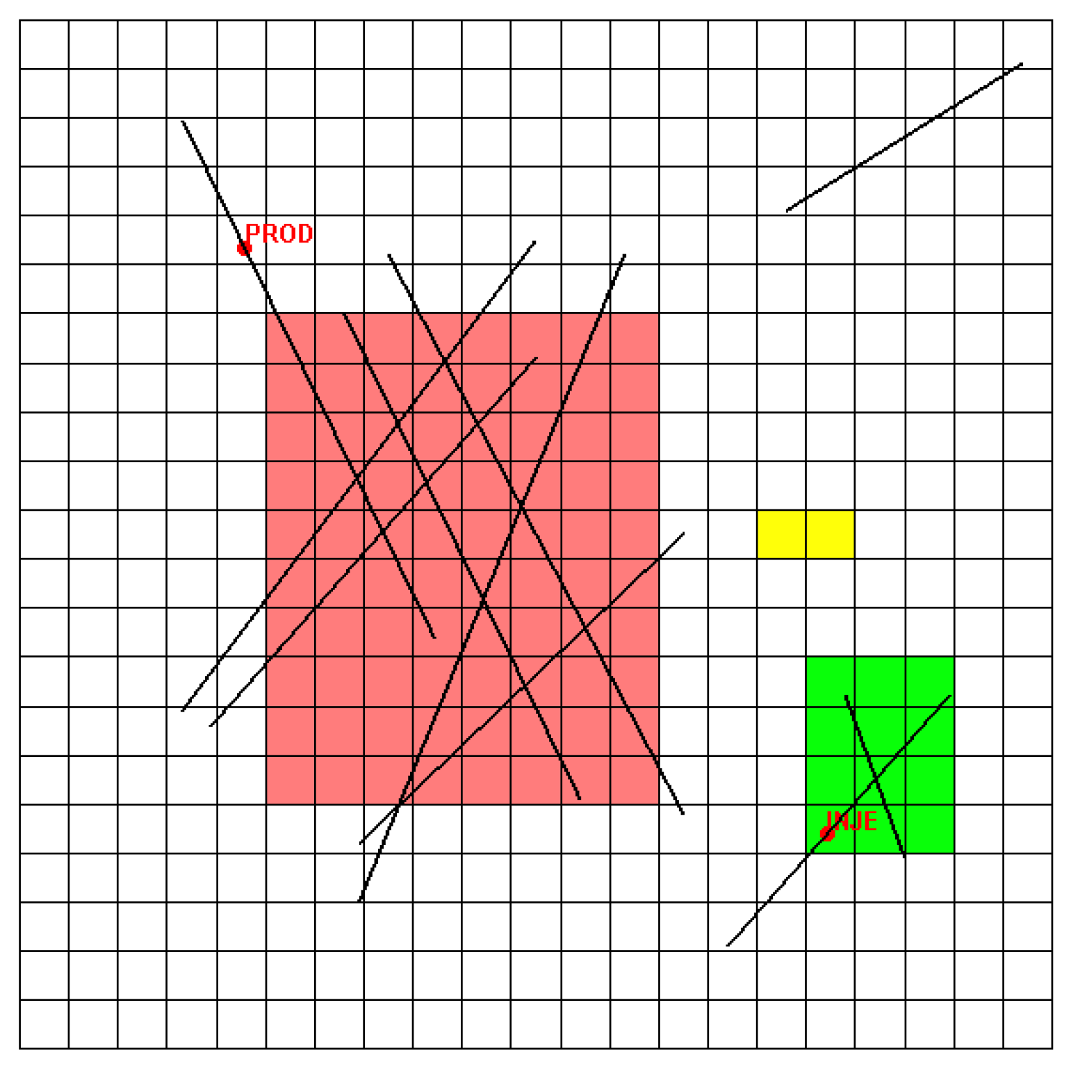
A given coarse block typically contains a network of fractures. The local boundary conditions have to be represented carefully in regions with high fracture density. In order to balance the computational accuracy and efficiency, the extended range of each local region is determined according to fracture density (P32). That is, the more fractures the coarse block contains, the larger local region will be used.
In addition to the fracture networks, well locations and conditions also have a strong impact on the flow. In former ALG works, a well region is considered separately to calculate well index. During local upscaling procedures, however, wells are excluded when determining transmissibilities. Besides, the radial distribution of pressure in near-well regions may also affect the boundary pressure interpolation, as will be discussed in Section 2.4. For these reasons, we introduce a well priority strategy that appends well boundary conditions once any wells are located inside the local region (as the green region shows in Figure 2). Note that, despite the fact that well conditions are included in a number of local regions during the entire workflow, the well properties, i.e., well indices, are still computed and updated in the well regions.
Figure 2. Adaptive extended local determination and near-well local region (region fracture density: red > green > yellow; the green local region has an injection well inside it).
Energies 08 10178 g002
Then, a single-phase incompressible solution of local pressure field is determined to count detailed matrix-matrix and fracture-fracture flow between adjacent coarse blocks and matrix-fracture flow exchange inside block. Balance equations of this type are written as Equation (4):
T Δ P = 0
With impermeable (zero flux) boundaries at first step and specific constant pressure boundaries latter respectively, the mass balance equations are solved to obtain pressure fields of local regions. Equation (5) is then used to compute coarse-scale transmissibilities:
T I J c = Q I J c P I c P J c
Here, T I J c is the transmissibility between coarse block I and J ; Q I J c is the total flow from coarse block I to J ; P I c and P J c are the coarse block pressures, which can be calculated by Equations (6) and (7):
P I c = i I P i f v i f v M , I c
Q I J c = i I , j J Q i j c

2.3. Global Solution under Coarse Grids

Using the connection list achieved above, it is easy to calculate the global single phase steady-state solution under coarse grids. For each local region, therefore, we can use the pressures of the coarse blocks to interpolate the pressures of the fine boundary blocks for the next iteration, which will be introduced below. This interpolation procedure updates the situation of extended local regions and is expected to improve the upscaled transmissibilities of the next extended local solution.

2.4. Pressure Interpolation Policy of Extended Local Boundary

Former ALG studies adopted a half grid extension for each local region. This treatment is quite convenient for Cartesian grids because the boundary fine cells are exactly on the lines connecting center points of coarse cells. In DFM upscaling procedures, however, it can hardly follow the strategy because the half range of a grid is difficult to determine and the relative position between fine and coarse grid centers is random due to the fine-scale grid is unstructured. In addition, former pressure interpolation uses a simple assumption of linear distribution of coarse pressure filed as shown in Equation (8):
P i f = P 1 c + D i 1 P 2 c P 1 c D 1 2
Here, D I J means the distance with a positive direction from I to J .
Equation (8) implies a totally linear pressure field around target local region, which may result in a bias in some situations. In the case where high heterogeneity exists or in near-well regions with high-speed radial flow, the deviation may be quite large. Therefore, in fracture reservoirs, it is necessary to distinguish the matrix and fracture media when interpolating boundary pressures.
Since transmissibility is a measurement of connectivity, the adjacent cells with higher transmissibility tend to have a closer pressure with the pressure propagation. Therefore, we use a transmissibility and inverse-distance related weighted strategy to determine the local fine boundary pressures. For example, to determine the pressure of the target fine block i , the weight of a specific coarse block J 0 must be positively-correlated to transmissibility between I and J 0 , and be negatively-correlated to distance between i and j , as shown in Equations (9) and (10):
P i f = J N I J w J P J c
w J 0 = T I J 0 c / D i J 0 J N I J ( T I J c / D i J )
Here, the N I J is the set containing all fine-scale connection pairs from coarse cell I to J , is the distance from center of fine-scale cell I to center of coarse-scale cell J .

2.5. Iteration Procedures and Convergence Condition

The procedures described above are iterated until convergence is obtained. Convergence here represents self-consistency between the global coarse-scale solution and upscaled properties. The convergence criteria are based on the changes in pressure or flow rate from one iteration to the next. Specific values used here are as Equation (11):
δ Q I J c , ( n ) < ε
Here, δ Q I J c , ( n ) is the coarse-scale flow difference between block I and J in the n -th iteration; ε is a threshold value defined according to specific models. Smaller ε is, stricter the iteration convergence condition will be.
We also set a maximum iteration number in case that sometimes it is not going to convergent to upscale a DFM model due to the high sensitivities of fracture conductivities. However, as we can find out in our cases, the simulation results after several iterations are going to convergent although the criteria above may not be reached.

3. Applications

3.1. Case 1: 2-D Model

The 2-D model contains 10 discrete fractures and two wells: one production well and one injection well respectively. The domain was discretized into 8618 fine hybrid unstructured grids including triangle volumes and 1-D fracture volumes (Figure 3). The target of upscaling procedure is a 21 by 21 coarse grid dual-porosity system. In order for us to fairly investigate the precision of different scales of grids, a linear variation of relative permeability was specified in both the matrix and fracture media and the capillary pressure was neglected for simplicity. Some other parameters of the model are shown in Table 1.
Figure 3. Case 1 model (a) model overview; (b) DFM grids.
Energies 08 10178 g003
Table 1. Model parameters of case 1.
Reservoir Properties
Domain7000 ft × 7000 ft (thickness = 1 ft)
Fine grid number (DFM)8614
Coarse grid number (Cartesian DPDK)21 × 21 for both matrix and fracture continua
Rock compressibility3 × 10−6/psi
Matrix permeability1 md
Matrix porosity0.1
Fracture permeability106 md
Fracture porosity1.0
Fracture aperture103 ft
Fluid Properties
Water viscosity1.0 cP
Water density64 lb/ft3
Oil viscosity1.0 cP
Oil density64 lb/ft3
Well Conditions
Water injection rate500 std/day (5.73 × 10⁴ PV/day)
We investigated four sets of simulations under coarse grids from different upscaling techniques: (1) global upscaling; (2) extended local upscaling; (3) adaptive local-global single-porosity (ALG-SP) upscaling; (4) adaptive local-global dual-porosity (ALG-DP) upscaling proposed in this paper. A fine-scale discrete fractured model is also simulated to provide a reference solution. Simulation results are shown in Figure 4 and Figure 5, while Figure 6, Figure 7 and Figure 8 show the comparison of saturation and pressure fields between fine model and coarse models [27]. The results demonstrate that the results proposed by this paper achieve a highest precision close to the global upscaling in both production rates and field dynamic variations during exploration. Particularly, it is worthy to note that saturation field of the dual-porosity model is much closer to the reference than that of single-porosity model in regions with high fracture density (as shown in Figure 5), which is due to the introduction of fracture continuum for upscaled model. Table 2 lists the consuming times of the different upscaled models. We can draw a conclusion that the ALG-DP raises the computational efficiency up to about 10 times with only a modest bias from the reference solution. Most of the filed contours in this paper are plotted using Matlab Reservoir Simulation Toolbox (MRST) [35].
Figure 4. (a) Oil rate and (b) water cut of production well for case 1.
Energies 08 10178 g004
Figure 5. Bottom hole pressure (BHP) of injection well for case 1.
Energies 08 10178 g005
Figure 6. Water saturation fields for case 1 at 365/1460/2555/3650 days. (a) DFM fine model; (b) ALG-SP coarse model; (c) ALG-DP coarse model.
Energies 08 10178 g006
Figure 7. Pressure cross plot for case 1 at (a) 365 days; (b) 1460 days; (c) 2555 days; (d) 3650 days.
Energies 08 10178 g007
Figure 8. Average field error comparison for case 1: (a) pressure error; (b) water saturation (SWAT) error.
Energies 08 10178 g008
Table 2. Simulation time and speed up for case 1.
ModelDFMGlobal UpscalingExtended Local UpscalingALG-SPALG-DP
Simulation Time (s)2094238222197210
Speed up ratio991110

3.2. Case 2: 3-D Model

In this case, we applied the upscaling technique to a 3-D model (Figure 9). The model and fracture system are similar to the 2-D case except for that we extended the vertical dimension into three layers with a total thickness of 360 ft. The same rock and fluid properties as case 1 are adopted. Other parameters are shown in Table 3. Conclusions similar to this case one can be drawn from simulation results listed in Figure 10, Figure 11, Figure 12, Figure 13 and Figure 14 and Table 4.
Figure 9. Case 2 model (a) model overview; (b) DFM grid.
Energies 08 10178 g009
Table 3. Model parameters of case 2.
ParameterValue
Domain7,000 ft × 7,000 ft × 360 ft
Fine grid number44,773
Coarse grid number11 × 11 × 3 (dual-porosity)
Figure 10. (a) Oil rate and (b) water cut of production well for case 2.
Energies 08 10178 g010
Figure 11. BHP of injection well for case 2.
Energies 08 10178 g011
Figure 12. Water saturation fields for case 2 at 365/1460/2555/3650 days. (a) DFM fine model; (b) ALG-SP coarse model; (c) ALG-DP coarse model.
Energies 08 10178 g012
Figure 13. Pressure cross plot for case 2 at (a) 365 days; (b) 1460 days; (c) 2555 days; (d) 3650 days.
Energies 08 10178 g013
Figure 14. Average field error comparison for case 2: (a) pressure error; (b) water saturation (SWAT) error.
Energies 08 10178 g014
Table 4. Simulation time and speed up for case 2.
ModelDFMGlobal UpscalingExtended Local UpscalingALG-SPALG-DP
Sim Time (s)118,649549619263496
Speed up216192451239

3.3. Case 3: Real Field Model

In this case, we considered a real field model in North West of China. As shown in Figure 15, the model is a 3D layered reservoir that consists of two layers with thicknesses of about 200 ft and 130 ft, respectively. The upper layer has higher porosity and permeability than the lower one. There are two wells in the reservoir: one for production and one for water injection. Relevant data of the model are list in Table 5.
Figure 15. Case 3 model: (a) model overview; (b) fracture distribution.
Energies 08 10178 g015
Table 5. Model parameters for case 3.
ParameterValue
Model region≈18,000 ft × 16,000 ft × 330 ft
Fine grid number (DFM)159,220
Coarse grid number (DPDK)17 × 15 × 5 (dual-porosity)
Rock compressibility3 × 10−6/psi
Matrix permeabilitylayer 1: 1 md; layer 2: 100 md
Matrix porositylayer 1: 0.1; layer 2: 0.2
Fracture permeability106 md
Fracture porosity1.0
Fracture aperture103 ft
Linear relative permeability was assumed and capillary was neglected in fracture medium. Relative permeability and capillary of the matrix medium are given by Equations (12)–(15), as shown in Figure 16. Other fluid and rock properties are shown in Table 6:
S * = S w S r w 1 S r w S r o
S w = ( S * ) 2
S o = ( 1 S * ) 2
P c = 14.5 ln S *
Figure 16. (a) Relative permeability and (b) capillary pressure of case 3.
Energies 08 10178 g016
Table 6. Case 3 fluid properties.
PropertyValue
Water viscosity1.0 cP
Water density64 lb/ft3
Oil viscosity3.0 cP
Oil density53 lb/ft3
S rw (water residual saturation)0.2
S ro (oil residual saturation)0.2
Water injection rate was fixed to 2.74 × 10⁻⁴ PV/day. The simulation results are shown in Figure 17, Figure 18 and Figure 19. Note that in the well plots, the pore volume injected (PVI) rather than time is used for evaluating the production performance against water injection. Simulation times each model costs are listed in Table 7. We note that although the upscaling technique proposed in this paper aims for upscaling the geometric transmissibility of grids, the coarse models can still be applied into more general types of models including situations where different fluid properties and capillary heterogeneity exist.
Figure 17. (a) Oil rate and (b) water cut of production well for case 3.
Energies 08 10178 g017
Figure 18. BHP of injection well for case 3.
Energies 08 10178 g018
Figure 19. Water saturation profiles at PVI = 1.0 for case 3: (a) matrix medium of fine model; (b) fracture medium of fine model; (c) matrix medium of coarse model; (d) fracture medium of coarse model.
Energies 08 10178 g019
Table 7. Simulation time for case 3.
ModelTime
Fine model (DFM)3637 s
Coarse model (DPDK)94 s

4. Conclusions

A new ALG upscaling method combining DPDK and DFM models for fractured reservoir has been devised and applied to several cases. There are several main features of the new approach:
(1)
The upscaling techniques are designed to handle DFM models based on unstructured meshes, which are difficult for region division and pressure interpolation procedures.
(2)
Dual continua mapping technique used in this method makes the coarse model become a dual-porosity dual-permeability model, which retains the ability to capture the features of flow through fractures. Compared to traditional statistics or semi-analytic approaches, local-global interaction procedures make the coarse DPDK properties more reliable for flow simulations.
(3)
The method was applied in several cases. The case 1 and case 2 demonstrate that this approach owns a high performance in efficiency and accuracy and can retain most of the heterogeneous features which can be seen in DFM models.
(4)
The technique proposed here is mainly applied for single-phase geometric transmissibility upscaling which is referred to as grid upscaling. The real-field case shows that, however, it can be applied to cases with more general fluid and rock properties. In addition, the procedures can be used as a foundation part of multi-phase upscaling procedures.

Acknowledgments

This work was supported by China National Petroleum Corporation (CNPC) major technology project “Research on Effective Development Technology of Low and Tight Low Permeability Reservoir”.

Author Contributions

Junchao Li designed the method, implemented the workflow and carried out the simulation cases. Zhengdong Lei provided ideas for the case design and provided important suggestions for paper revision. Guan Qin reviewed the final work and provided useful suggestions. All the work is conducted under the supervision of Bin Gong. All authors contributed to writing the paper.

Conflicts of Interest

The authors declare no conflict of interest.

References

  1. Barenblatt, G.I.; Zheltov, Y.P. Fundamental equations for the filtration of homogeneous fluids through fissured rocks. Dokl. Akad. Nauk SSSR 1960, 132, 545–548. [Google Scholar]
  2. Warren, J.E.; Root, P.J. The Behavior of Naturally Fractured Reservoirs. Soc. Pet. Eng. J. 1963, 3, 245–255. [Google Scholar] [CrossRef]
  3. Thomas, L.K.; Dixon, T.N.; Pierson, R.G. Fractured Reservoir Simulation. Soc. Pet. Eng. J. 1983, 23, 42–54. [Google Scholar] [CrossRef]
  4. Kazemi, H.; Merrill, L.S., Jr.; Porterfield, K.L.; Zeman, P.R. Numerical simulation of water-oil flow in naturally fractured reservoirs. Soc. Pet. Eng. J. 1976, 16, 317–326. [Google Scholar] [CrossRef]
  5. Coats, K.H.; Dempsey, J.R.; Henderson, J.H. The use of vertical equilibrium in two-dimensional simulation of three-dimensional reservoir performance. Soc. Pet. Eng. J. 1971, 11, 63–71. [Google Scholar] [CrossRef]
  6. Dean, R.H.; Lo, L.L. Simulations of naturally fractured reservoirs. SPE Reserv. Eng. 1988, 3, 638–648. [Google Scholar] [CrossRef]
  7. Rossen, R.H.; Shen, E.I.C. Simulation of gas/oil drainage and water/oil imbibition in naturally fractured reservoirs. SPE Reserv. Eng. 1989, 4, 464–470. [Google Scholar] [CrossRef]
  8. Penuela, G.; Hughes, R.G.; Civan, F.; Wiggins, M.L. Time-dependent shape factors for secondary recovery in naturally fractured reservoirs. In Proceedings of the SPE/DOE Improved Oil Recovery Symposium, Tulsa, OK, USA, 13–17 April 2002; Society of Petroleum Engineers: Richardson, TX, USA, 2002. [Google Scholar]
  9. Baca, R.G.; Arnett, R.C.; Langford, D.W. Modelling fluid flow in fractured-porous rock masses by finite-element techniques. Int. J. Numer. Methods Fluids 1984, 4, 337–348. [Google Scholar] [CrossRef]
  10. Juanes, R.; Samper, J.; Molinero, J. A general and efficient formulation of fractures and boundary conditions in the finite element method. Int. J. Numer. Methods Eng. 2002, 54, 1751–1774. [Google Scholar] [CrossRef]
  11. Kim, J.G.; Deo, M.D. Finite element, discrete-fracture model for multiphase flow in porous media. AIChE J. 2000, 46, 1120–1130. [Google Scholar] [CrossRef]
  12. Karimi-Fard, M.; Firoozabadi, A. Numerical simulation of water injection in fractured media using the discrete-fracture model and the Galerkin method. SPE Reserv. Evaluation Eng. 2003, 6, 117–126. [Google Scholar] [CrossRef]
  13. Karimi-Fard, M.; Durlofsky, L.J.; Aziz, K. An efficient discrete-fracture model applicable for general-purpose reservoir simulators. SPE J. 2004, 9, 227–236. [Google Scholar] [CrossRef]
  14. Hoteit, H.; Firoozabadi, A. Compositional modeling of discrete-fractured media without transfer functions by the discontinuous Galerkin and mixed methods. SPE J. 2006, 11, 341–352. [Google Scholar] [CrossRef]
  15. Hoteit, H.; Firoozabadi, A. An efficient numerical model for incompressible two-phase flow in fractured media. Adv. Water Resour. 2008, 31, 891–905. [Google Scholar] [CrossRef]
  16. Hoteit, H.; Firoozabadi, A. Numerical modeling of two-phase flow in heterogeneous permeable media with different capillarity pressures. Adv. Water Resour. 2008, 31, 56–73. [Google Scholar] [CrossRef]
  17. Hui, M.; Mallison, B.T.; Fyrozjaee, M.H.; Narr, W. The Upscaling of Discrete Fracture Models for Faster, Coarse-Scale Simulations of IOR and EOR Processes for Fractured Reservoirs. In Proceedings of the SPE Annual Technical Conference and Exhibition, New Orleans, LA, USA, 30 September–2 October 2013; Society of Petroleum Engineers: Richardson, TX, USA, 2013. [Google Scholar]
  18. Farmer, C.L. Upscaling: A review. Int. J. Numer. Methods Fluids 2002, 40, 63–78. [Google Scholar] [CrossRef]
  19. Durlofsky, L.J. Upscaling of geocellular models for reservoir flow simulation: A review of recent progress. In Proceedings of the 7th International Forum on Reservoir Simulation, Bühl/Baden-Baden, Germany, 23–27 June 2003.
  20. Bourgeat, A. Two-phase flow. In Homogenization and Porous Media; Springer: New York, NY, USA, 1997; pp. 95–127. [Google Scholar]
  21. Bourgeat, A.; Panfilov, M. Effective two-phase flow through highly heterogeneous porous media: Capillary nonequilibrium effects. Comput. Geosci. 1998, 2, 191–215. [Google Scholar] [CrossRef]
  22. Desbarats, A.J. Upscaling Capillary Pressure-Saturation Curves in Heterogeneous Porous Media. Water Resour. Res. 1995, 31, 281–288. [Google Scholar] [CrossRef]
  23. Dershowitz, B.; LaPointe, P.; Eiben, T.; Wei, L. Integration of discrete feature network methods with conventional simulator approaches. SPE Reserv. Evaluation Eng. 2000, 3, 165–170. [Google Scholar] [CrossRef]
  24. Sarda, S.; Jeannin, L.; Basquet, R.; Bourbiaux, B. Hydraulic characterization of fractured reservoirs: Simulation on discrete fracture models. SPE Reserv. Evaluation Eng. 2002, 5, 154–162. [Google Scholar] [CrossRef]
  25. Li, L.; Lee, S.H. Efficient field-scale simulation for black oil in a naturally fractured reservoir via discrete fracture networks and homogenized media. In Proceedings of the International Oil & Gas Conference and Exhibition in China, Beijing, China, 5–7 December 2006.
  26. Vitel, S.; Souche, L. Unstructured upgridding and transmissibility upscaling for preferential flow paths in 3D fractured reservoirs. In Proceedings of the SPE Reservoir Simulation Symposium, Houston, TX, USA, 26–28 February 2007.
  27. Karimi-Fard, M.; Gong, B.; Durlofsky, L.J. Generation of coarse-scale continuum flow models from detailed fracture characterizations. Water Resour. Res. 2006, 42. [Google Scholar] [CrossRef]
  28. Gong, B.; Karimi-Fard, M.; Durlofsky, L.J. Upscaling Discrete Fracture Characterizations to Dual-Porosity, Dual-Permeability Models for Efficient Simulation of Flow With Strong Gravitational Effects. SPE J. 2008, 13, 58–67. [Google Scholar] [CrossRef]
  29. Chen, Y.; Durlofsky, L.J.; Gerritsen, M.; Wen, X.H. A coupled local-global upscaling approach for simulating flow in highly heterogeneous formations. Adv. Water Resour. 2003, 26, 1041–1060. [Google Scholar] [CrossRef]
  30. Chen, Y. Upscaling and Subgrid Modeling of Flow and Transport in Heterogeneous Reservoirs; Stanford University: Stanford, CA, USA, 2005. [Google Scholar]
  31. Chen, Y.; Durlofsky, L.J. Adaptive Local-Global Upscaling for General Flow Scenarios in Heterogeneous Formations. Transp. Porous Media 2006, 62, 157–185. [Google Scholar] [CrossRef]
  32. Durlofsky, L.J.; Efendiev, Y.; Ginting, V. An adaptive local-global multiscale finite volume element method for two-phase flow simulations. Adv. Water Resour. 2007, 30, 576–588. [Google Scholar] [CrossRef]
  33. Shewchuk, J.R. Triangle: Engineering a 2D quality mesh generator and Delaunay triangulator. In Applied Computational Geometry towards Geometric Engineering; Springer: New York, NY, USA, 1996; pp. 203–222. [Google Scholar]
  34. Si, H. TetGen. A 3D Delaunay Tetrahedral Mesh Generator. V. 1.2 Users Manual; WIAS Technical Report; WIAS: Berlin, Germany, 2002. [Google Scholar]
  35. Lie, K.A. An Introduction to Reservoir Simulation Using MATLAB: User Guide for the Matlab Reservoir Simulation Toolbox (MRST); SINTEF ICT: Trondheim, Norway, 2014. [Google Scholar]

