1. Introduction
Recently, the integration of renewable energy systems into the electric power grid has received great attention in both academia and industry. It is expected that the eventual integration level of renewable energy systems will be vast, and their control will become more challenging [
1]. As wind and solar power are the best-known and famous examples, the focus will be on these renewable energy systems. There are two types of renewable energy system: large-scale wind and solar farms located in remote areas, and small-scale wind turbines (WTs) and photovoltaic (PV) panels connected to the electric distribution system. The focus of this study will be small-scale renewable energy systems.
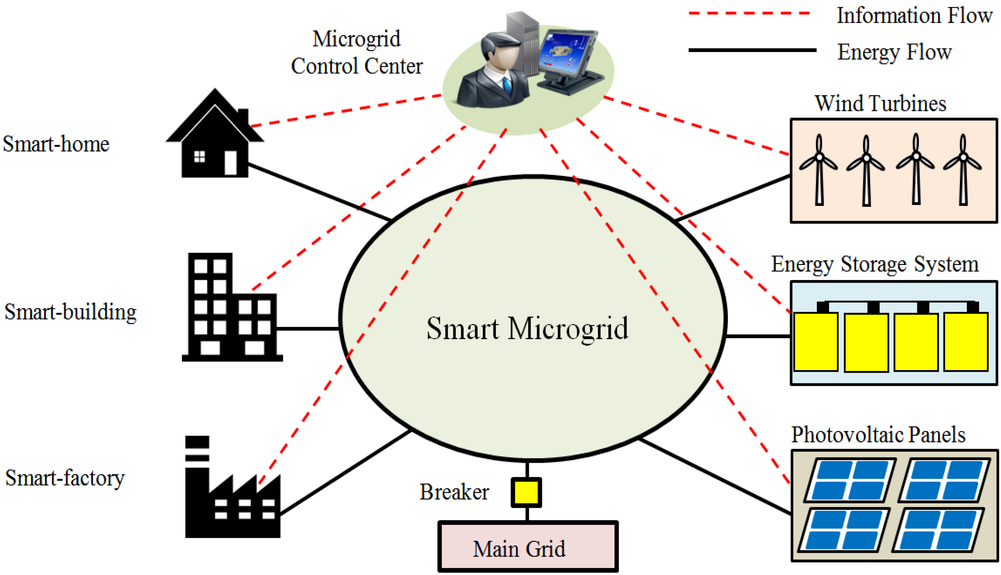
Nowadays, many customers and households have begun to install small-scale WTs and PV panels as standalone systems to meet some of their energy needs locally. The microgrid system can be defined as a low/medium voltage electric power system that contains renewable energy systems, an energy storage system, controllable loads, and an energy management system [
2]. The size of a microgrid system can range from a single household to a large geographic area such as a campus. Energy consumers/producers such as a home, building, factory, or campus can use small-scale renewable energy systems to manage themselves either in island mode or connected to the main grid [
3,
4]. The customer may feed the excess power into the grid or store it using energy storage systems to be used when needed. The communication infrastructure is considered the fundamental element that allows monitoring and control of the operation of the renewable energy systems. In addition, it enables the transfer of both measured information and control signals between the renewable energy systems and the control center [
5].
The deployment of renewable energy systems is considered key for enabling technology toward the future smart grid implementation that will change the way we produce and consume electricity. Under certain conditions, these systems will be able to supply the needed electricity to isolated/remote locations. However, managing and controlling the operation of renewable energy systems on a large scale will present many challenges [
6]. In order to achieve reliable, secure, and cost-efficient operation of renewable energy systems, as well as the microgrid systems, information and communication technologies are considered an essential element. In this regard, many aspects of the communications technology need to be studied, and their performance should be investigated in order to make the smart-microgrid a reality.
Few papers in the literature have studied the communications infrastructure of small-scale renewable energy systems. In one study [
7], a hybrid solar-wind energy system was designed for domestic applications such as rural and remote areas. This system consisted of solar panels, wind generators, load controller, batteries, and inverter. The system could be operated in grid-connected mode as well as off-grid mode. In another study [
8], the authors designed and implemented a domestic solar-wind energy system that was monitored and controlled in real time. Measurement of current and voltage from the WT and the solar panels in the implemented system was carried out using three current sensors and three voltage sensors. Sharafat
et al. [
9] described a distributed Ethernet-based communication network for monitoring a hybrid system consisting of solar PV and a diesel power generator in a local electricity grid. Direct communications links were established between the hybrid system and the control center. Furthermore, the communication links were configured in a star topology. Rashidi
et al. [
10] proposed a cost-effective PV monitoring system using wireless technology (ZigBee). In order to monitor real-time measurements such as voltage, current, and power of each module, a graphical user interface was developed using LabView. A real microgrid project in Girona, Spain was presented by Salas
et al. in [
11]. The project was configured as a standalone system consisting of PV panels, a small WT, energy storage system (batteries), and micro combined heat and power. A cost-effective monitoring system was carried out using ZigBee technology. In [
12], Kang
et al. implemented a condition monitoring and control system for a small-scale WT. It consists of data collection unit, control unit and a coordinator. The data collection units were used to collect data from various sensors such as temperature, pressure, humidity, wind speed and wind direction. ZigBee was used to communicate between the data collection units and the coordinator. Another study [
13] applied the small wind generation system to a super high-rise building. Vibration and noise measurements were performed for both horizontal and vertical WT installations.
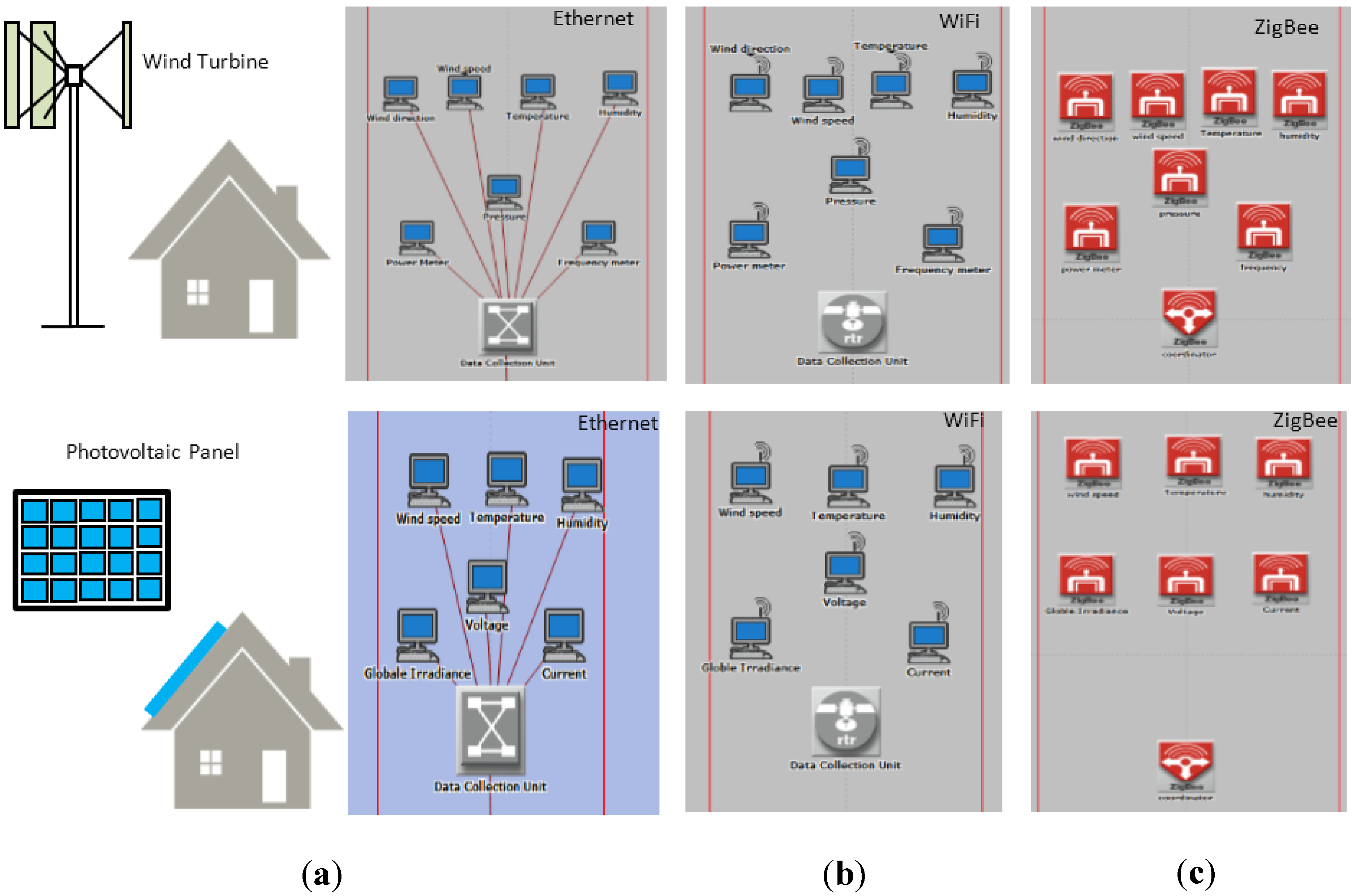
Few papers have studied the communications infrastructure and networking of small-scale renewable energy systems. Most research work has focused on the electric engineering and electric control aspects [
14]. In order to monitor the behavior of small-scale renewable energy systems, different types of sensors should be considered. Furthermore, considering only one wired/wireless technology for the communication infrastructure is not the best solution because of the restrictions or obstacles that may exist in system deployment. The main objective of the current paper is to design communication network architecture for monitoring the behavior of renewable energy generation involving small-scale WTs and PV systems based on international electrotechnical commission standards. A simulation model using three different technologies: Ethernet-based, Wi-Fi-based and ZigBee-based, was designed using the OPNET Modeler. The performance of the proposed network models was evaluated with respect to end-to-end (ETE) delay for different architectures, including a smart-house and a smart-building. The major contributions of this work are as follows:
Design of communication network architecture for monitoring and controlling small-scale distributed energy systems using both wired and wireless technologies.
Define the traffic profile and data packet size of renewable energy systems including small-scale WTs and PV systems.
Evaluate the performance using three different technologies: Ethernet-based, WiFi-based, and ZigBee-based architectures.
Compare the performance of communication networks with respect to the ETE delay, reliability and network cost for different architectures including a smart-house and a smart-building.
3. Network Architecture for Small-Scale Renewable Energy Systems
The communication network is considered an essential component to ensure a reliable and stable renewable energy systems operation. When designing the microgrid communication network, the three major factors that should be considered are the microgrid components, traffic volume, and number of renewable energy systems.
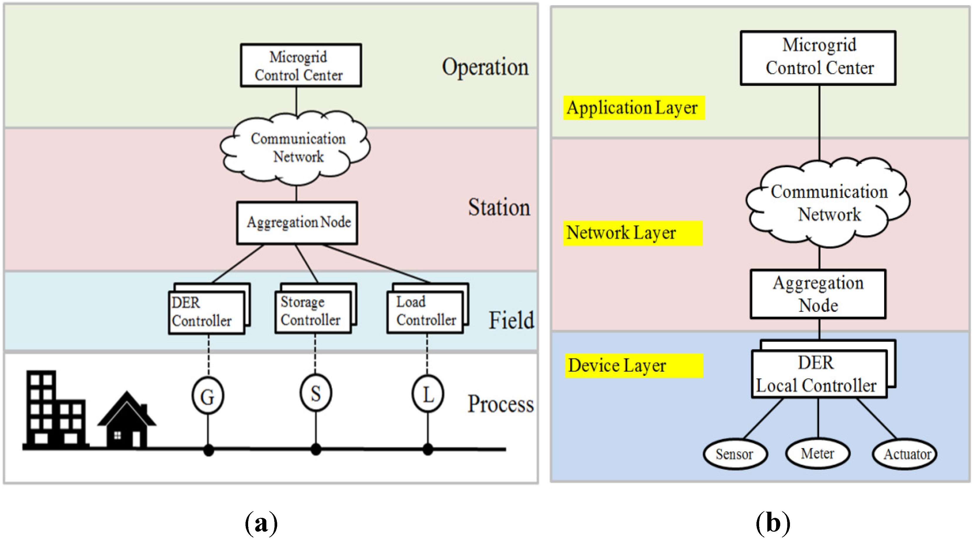
Figure 3 shows the three layers of communication architecture of the microgrid based on the smart grid coordination group [
20]: the device layer, network layer, and application layer.
The device layer represents various devices including sensor nodes and meters which are used to capture different measurements such as voltage, current, and temperature from the renewable energy units. Each renewable energy unit has a local controller. The local controller monitors and controls the operation of the renewable energy unit based on local measurements.
The network layer is used to connect the device layer components and the microgrid control center. The network layer should support real-time monitoring and control of the microgrid system. It can be established either using wired or wireless-based technologies.
The application layer is responsible for energy management and remote monitoring and control of the microgrid system. It includes the SCADA system that receives the measurement data via the network layer.
Figure 3.
(a) Smart grid customer premises domain and hierarchical zones; (b) Microgrid three layers communication network architecture.
Figure 3.
(a) Smart grid customer premises domain and hierarchical zones; (b) Microgrid three layers communication network architecture.
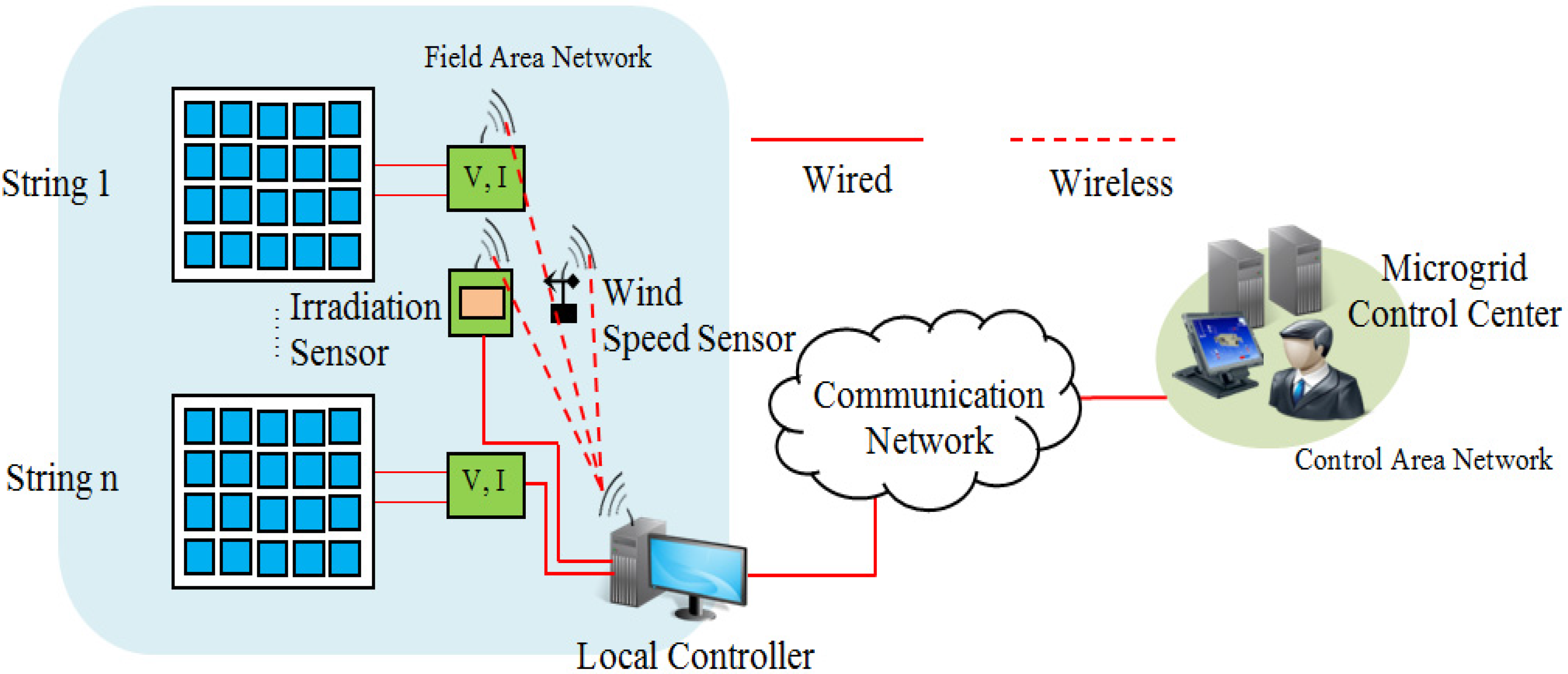
3.1. Network Model of PV System
The PV power system is used to convert the solar energy into electricity. It consists of several modules connected to form module strings. The modules are connected in different topologies in series or parallel to form an array. The PV power system can be operated in a standalone mode, combined with other renewable energy sources, or connected to the main power system. The output voltage of the PV system may be affected if a fault occurs in any single module that may degrade the system output. Other factors that may degrade the system performance are shading and dust. In this study, the International Electrotechnical Commission (IEC) 61724 standard is used to describe general guidelines for monitoring and analysis of the PV systems [
21]. Based on IEC 61724, we defined the real-time monitoring parameters of the PV system as given in
Table 3. All monitoring parameters should be continuously measured, and the sampling interval should be 1 min or less.
Table 3.
Monitoring parameters of a PV system based on IEC 61724.
Table 3.
Monitoring parameters of a PV system based on IEC 61724.
| Type | Measurement | Accuracy Range | Sampling Freq. |
|---|
| Meteorology | Total Irradiance | <5% | 1 min or less |
| Ambient Air Temperature | <1 °C |
| Wind Speed | <0.5 m/s for speed <5 m/s, <10% of the reading for speed >5 m/s |
| PV Array | Output Voltage | <1% of the reading | 1 min or less |
| Output Current | <1% of the reading |
| Output Power | <1% of the reading |
| Module Temperature | <1 °C |
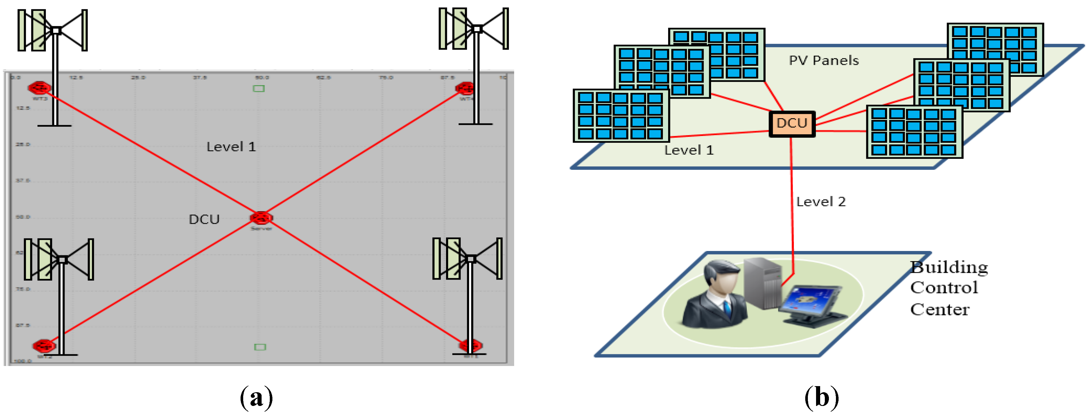
Figure 4 shows the communication network for the PV system. To monitor the system continuously, different sensor nodes are installed that enable the control center operator to detect any fault and allow a rapid response to control the system operation. The monitored parameters include voltage, current, power, panel temperature, wind speed, air temperature, and irradiation sensors. All sensing data are collected at the control center level.
Figure 4.
Communication network for a PV system.
Figure 4.
Communication network for a PV system.
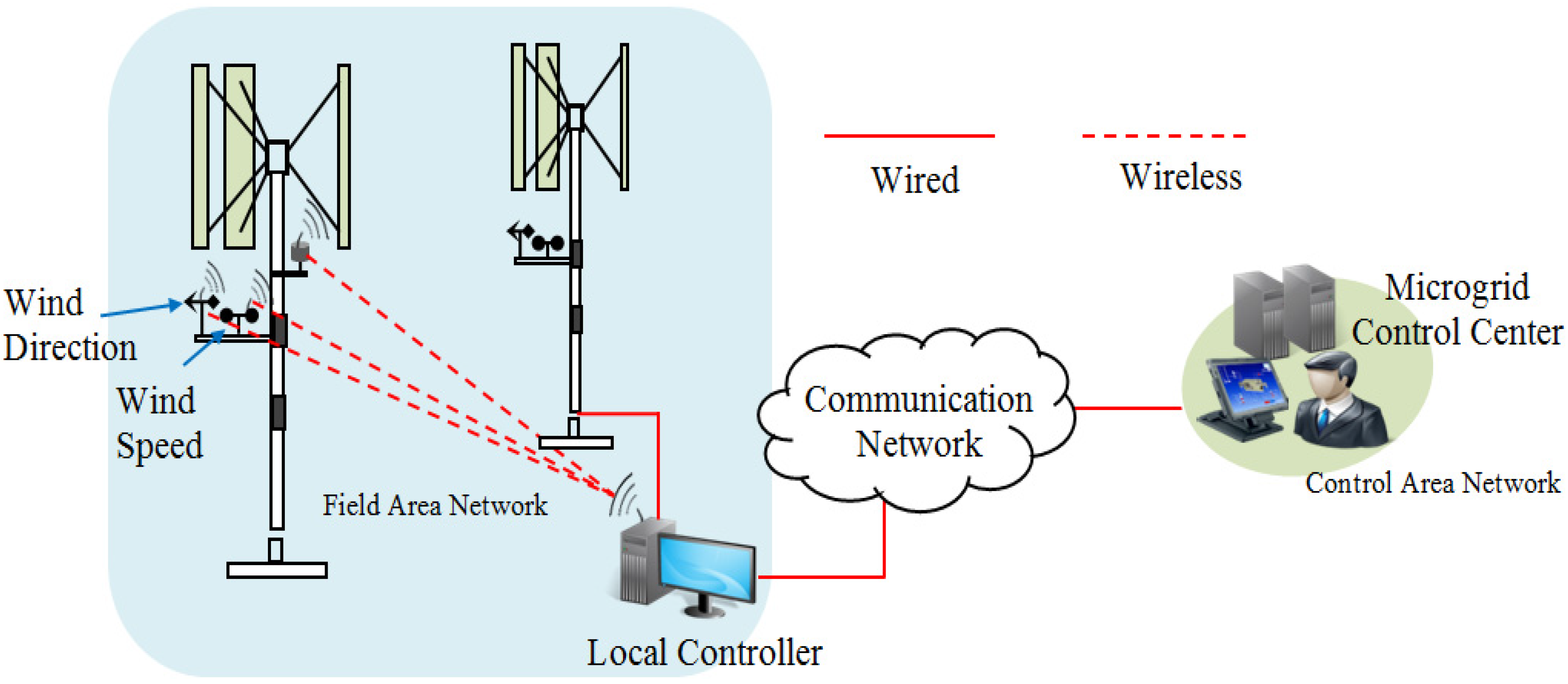
3.2. Network Model of Small-Scale WT System
WTs can be classified based on power production into three types: utility scale, industrial scale, and residential scale. Large WTs are used for utility power generation in wind farms whereas small-scale WTs are better suited for residential and small business. In this study, the monitoring requirements of small-scale WTs are based on Commonwealth wind incentive program [
22] and Ahmed
et al. [
23]. The measurement parameters include wind speed, wind direction, outdoor temperature, and turbine output power, as shown in
Table 4. The wind speed is measured by an anemometer and the wind direction is measured by a wind vane.
Figure 5 shows the communication network for a small-scale WT.
Table 4.
Monitoring parameters of small-scale WT.
Table 4.
Monitoring parameters of small-scale WT.
| Measurement | Equipment | Accuracy Range | Sampling Freq. |
|---|
| Wind Speed | Anemometer | ±0.1 m/s | 1 min or less |
| Wind Direction | Wind Vane | ±5° |
| Outdoor Temperature | Temperature Sensor | ±2 °C |
| Turbine Output Power | Watt Transducer | ±1% of reading |
| Pressure | Pressure Sensor | – |
Figure 5.
Communication network for a small-scale WT.
Figure 5.
Communication network for a small-scale WT.
3.3. Network Model of Microgrid Control Center
The microgrid control center includes the human machine interface, energy management system, and data storage servers. It collects all information from renewable energy systems, energy storage systems, and loads through the communication networks.
3.4. Measuring Requirements for Sensor Data
This section shows the different measurements that should be considered in order to perform real-time monitoring of renewable energy systems.
Table 5 lists all the measurements and their sampling frequency [
24]. These sensors collect data and transmit them to the data collection unit (DCU), located at the WT or PV site. For each sensor node, we defined the measurement type, the sampling frequency, and the number of channels needed. As shown in
Table 5, we calculated the amount of data transferred per second from each sensor node to the DCU, assuming that each sample is represented by 16 bits (2 bytes) [
25]. Data rate can be calculated according to Equation 1 where, N
c and
fs represent the number of channels and sampling frequency, respectively.
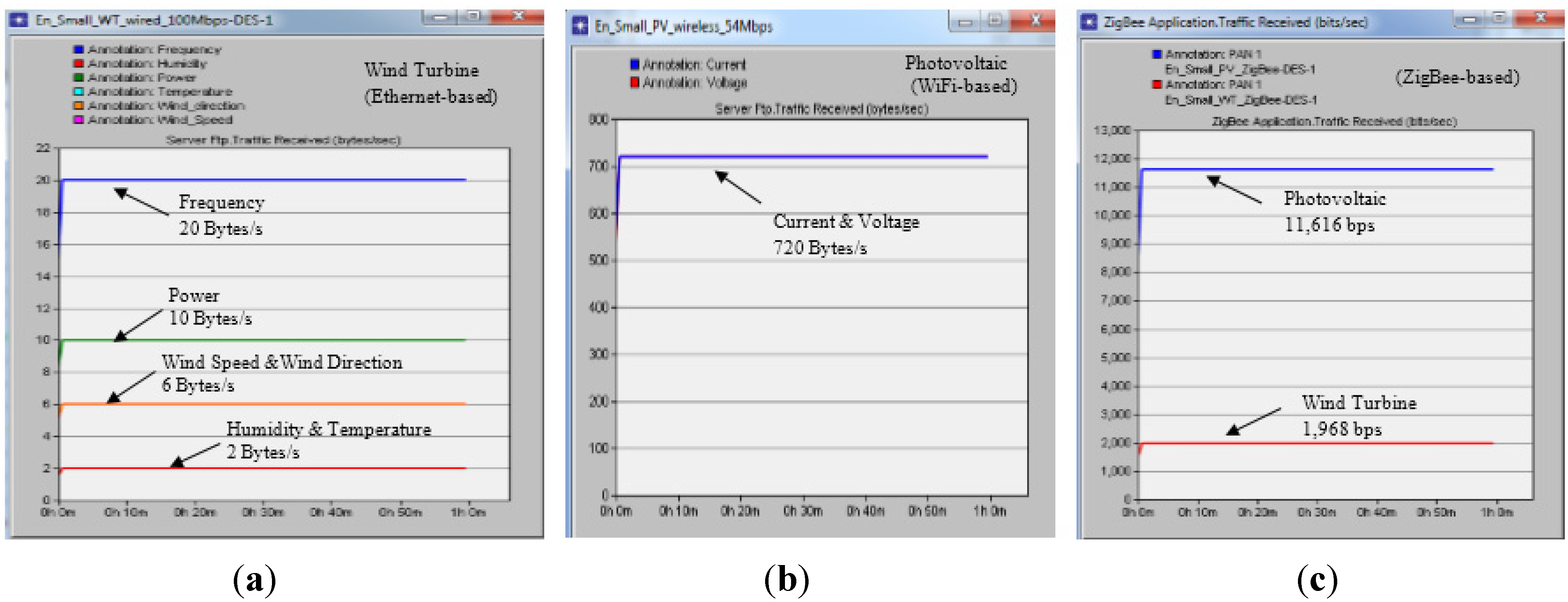
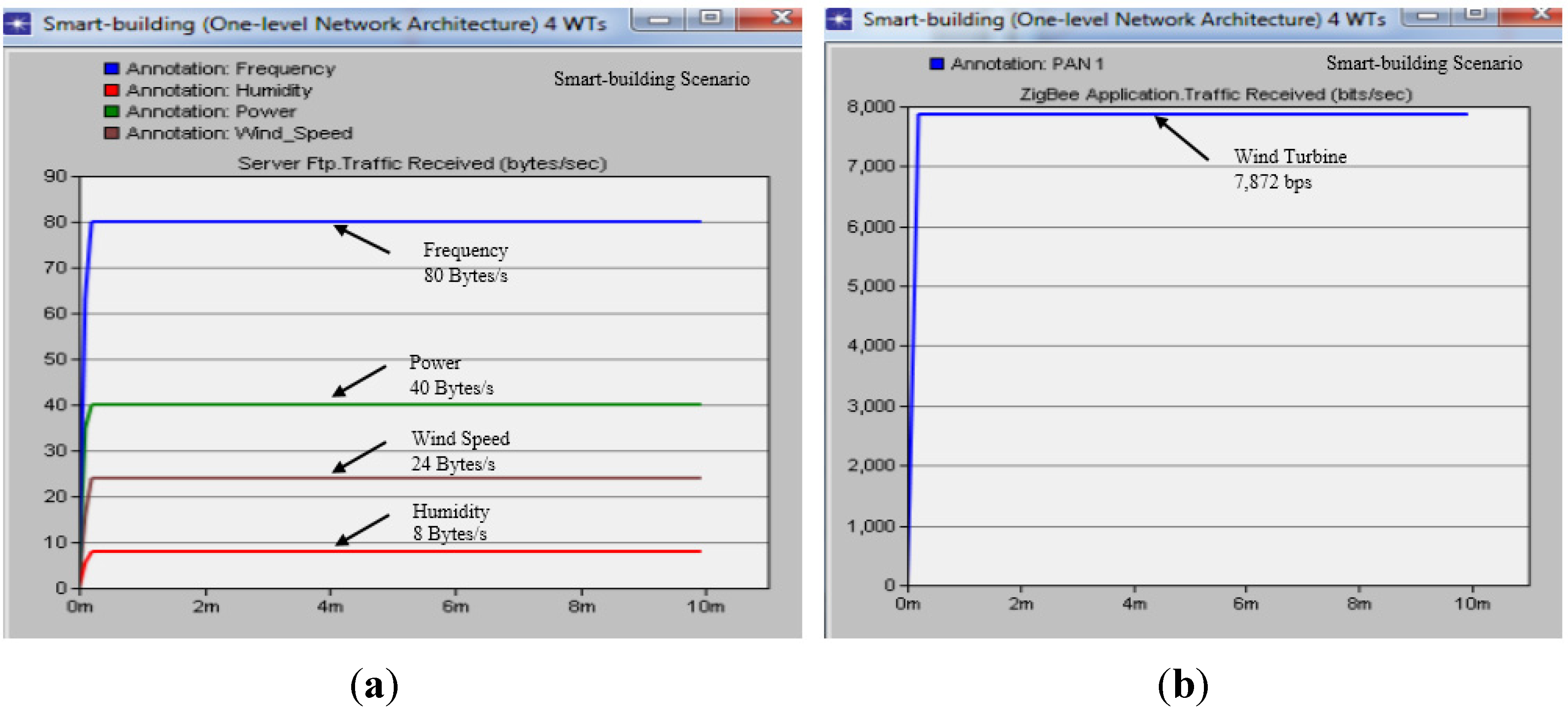
The total amount of traffic for a WT and a PV system can be calculated according to the number of sensors. Real-time measurements considered for WTs include wind speed, wind direction, temperature, humidity, pressure, frequency, and output power, whereas those for PV systems include voltage, current, wind speed, humidity, irradiation, and module temperature.
Table 5.
Measuring requirements for sensor data.
Table 5.
Measuring requirements for sensor data.
| Measurement | Unit | Sampling Frequency | # of Channels | Direction | Size (Bytes) |
|---|
| Temperature | C | 1 Hz | 1 | Uplink/Continuous | 2 |
| Pressure | Pa | 100 Hz | 1 | Uplink/Continuous | 100 |
| Power | W | 5 Hz | 1 | Uplink/Continuous | 10 |
| Wind Direction | deg | 3 Hz | 1 | Uplink/Continuous | 6 |
| Wind Speed | m/s | 3 Hz | 1 | Uplink/Continuous | 6 |
| Frequency | Hz | 10 Hz | 1 | Uplink/Continuous | 20 |
| Global Irradiance | Pa | 100 Hz | 1 | Uplink/Continuous | 200 |
| Humidity | % | 1 Hz | 1 | Uplink/Continuous | 2 |
| Voltage | V | 360 Hz | 1 | Uplink/Continuous | 720 |
| Current | A | 360 Hz | 1 | Uplink/Continuous | 720 |
| WT | 246 bytes/s ≈ 1968 bit/s |
| PV | 1452 bytes/s ≈ 11,616 bit/s |
5. Conclusions
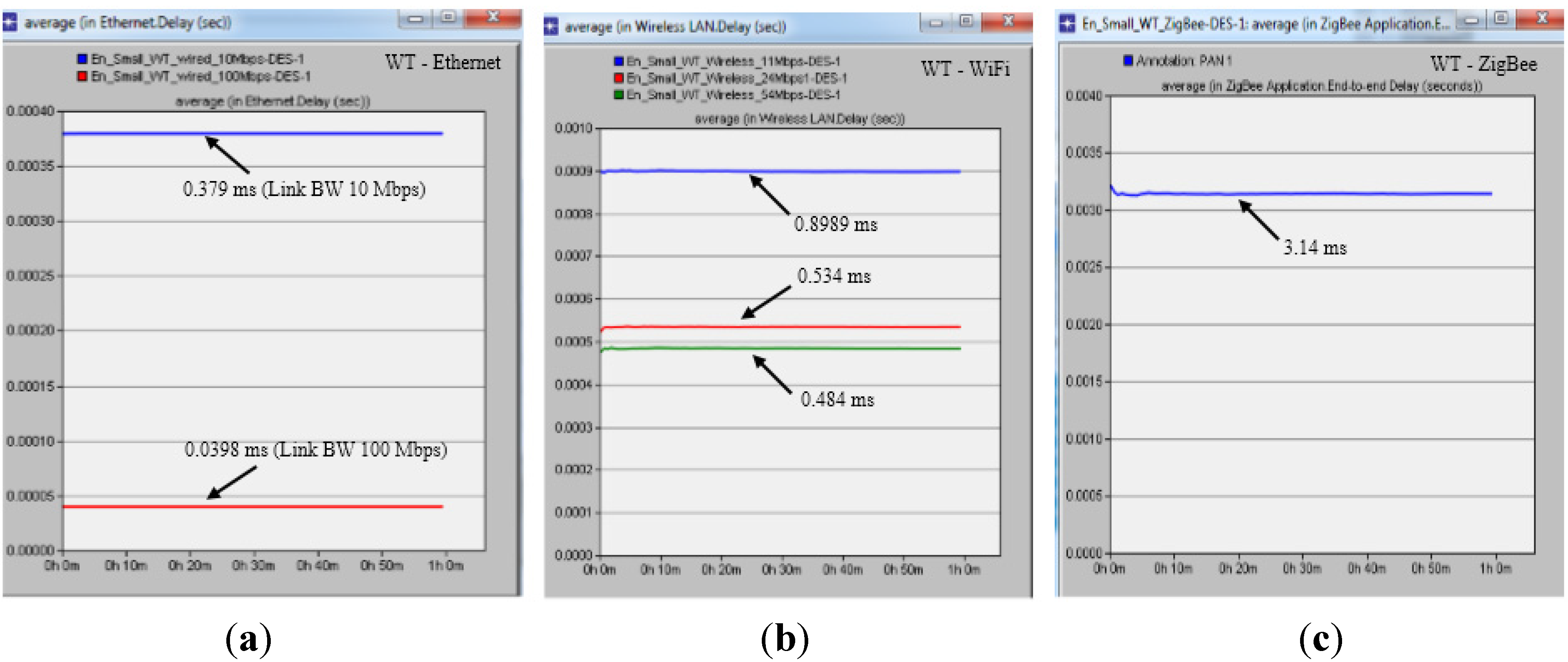
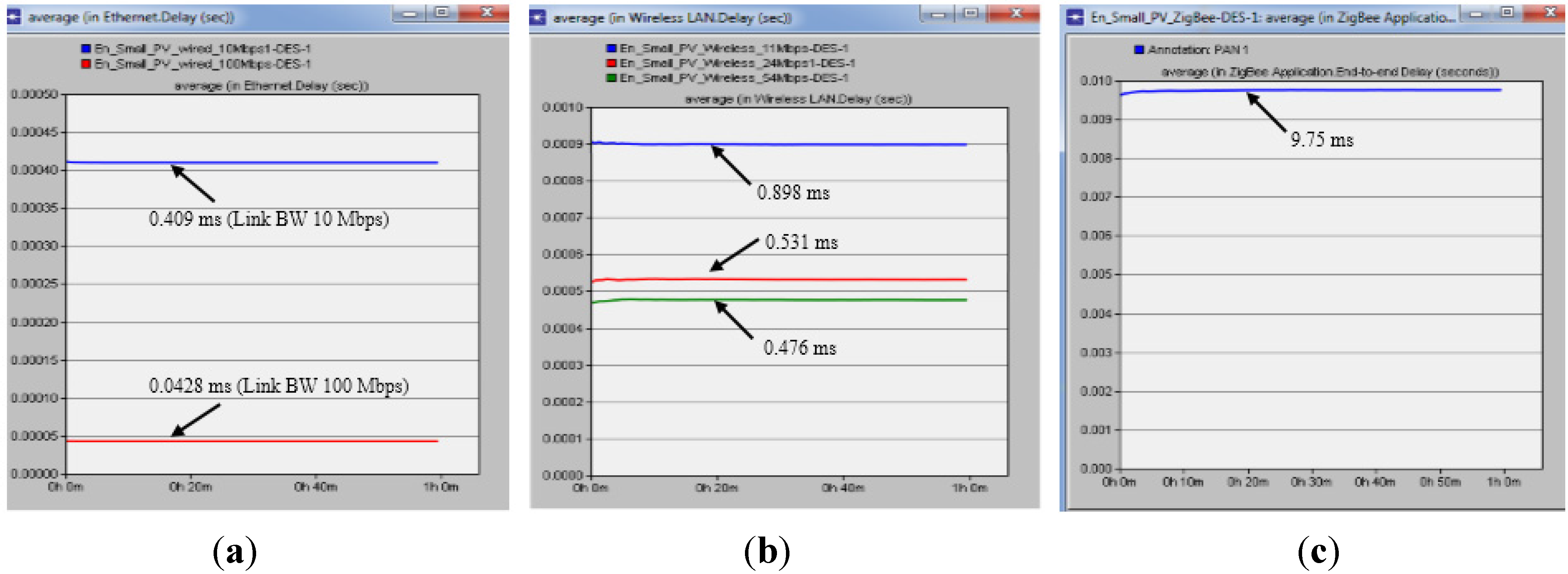
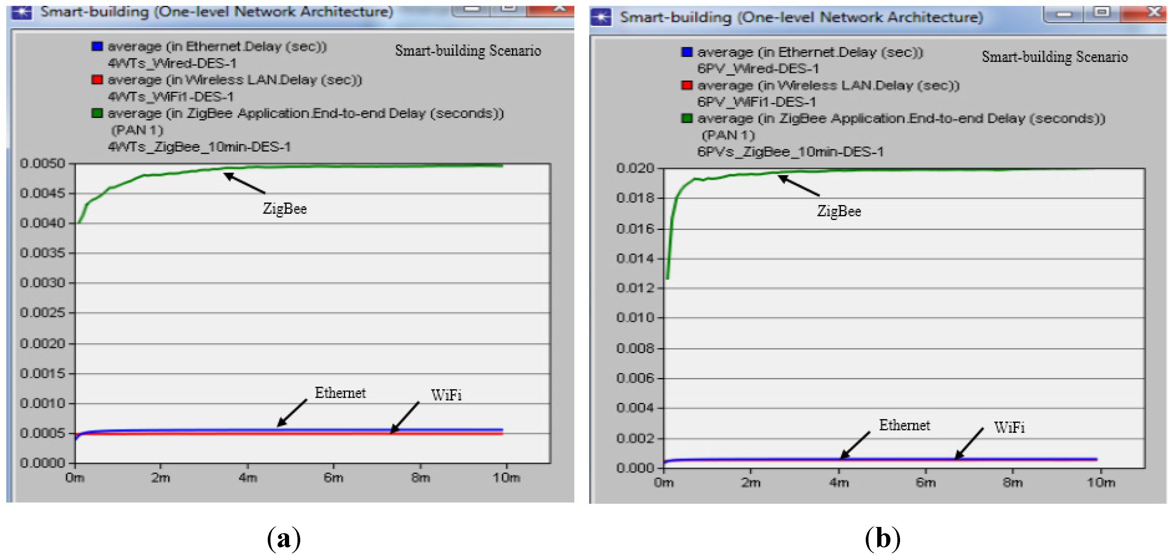
In this paper, we proposed three alternative communication network architectures for monitoring the behavior of small-scale renewable energy system with small WTs and PVs. We defined the measurement requirements, traffic profile, and data packet size of renewable energy systems according to the IEC standard. We also explored network architectures and topologies using both wireless and wired technologies. The proposed communication network architectures were modeled and simulated by an OPNET Modeler. Our simulator was validated by comparing the amount of received traffic at the server with results of numerical analysis. Two scenarios were considered: a smart-house and a smart-building.
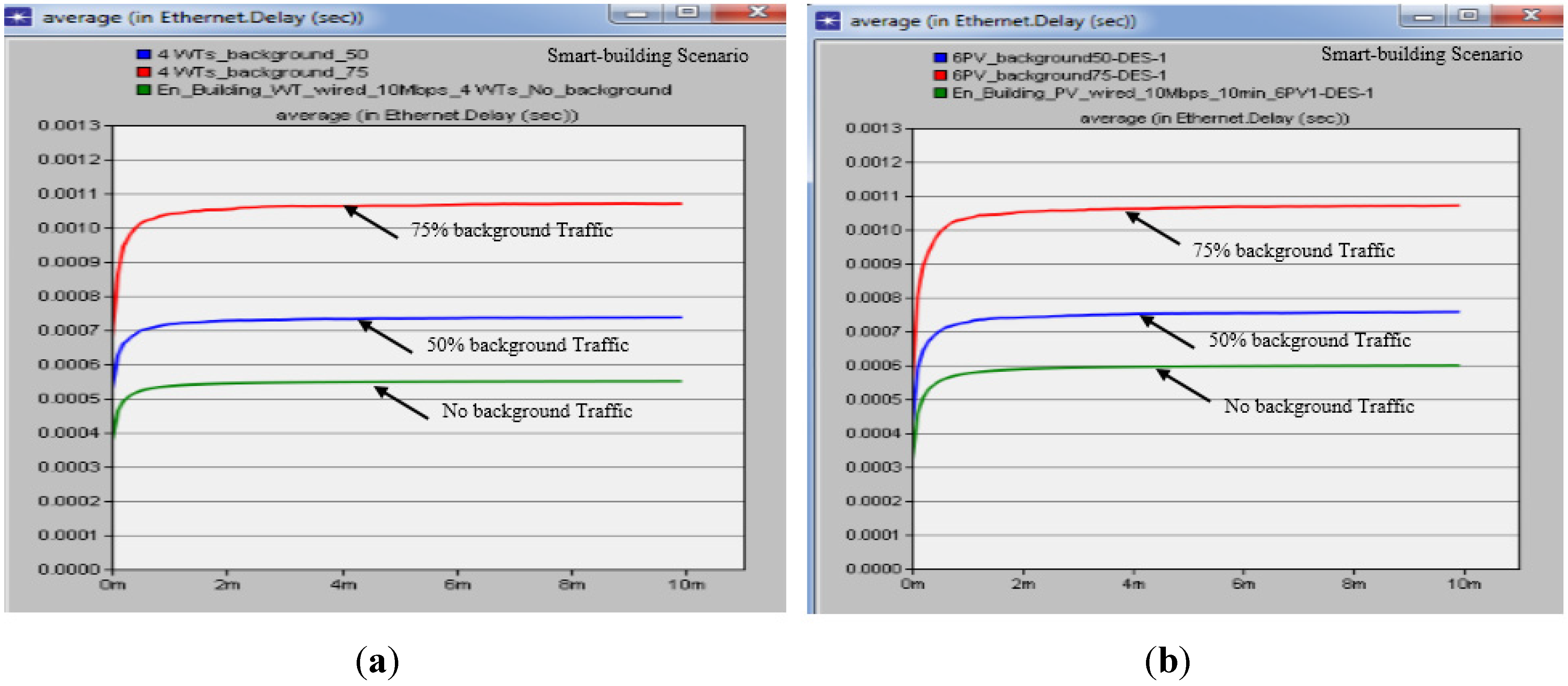
For the smart-house scenario, we observed that the average ETE delay for the PV system was approximately 0.409 ms, 0.476 ms, and 9.75 ms for Ethernet (10 Mbps), WiFi (54 Mbps) and ZigBee (250 kbps), respectively. Simulation results of the proposed architectures were within the upper boundary of 4 ms required for power system protection except for the ZigBee-based architecture. For the smart-building scenario, the average ETE delay for the four PV systems was approximately 0.595 ms, 0.497 ms, and 13.35 ms for Ethernet (10 Mbps), WiFi (54 Mbps), and ZigBee (250 kbps), respectively. For the Ethernet-based architectures under background traffic, the average ETE delay was approximately 0.747 ms and 1.039 ms for background of 50% and 75%, respectively. Also, the simulation results of the smart-building were within the upper boundary of 4 ms. Reliability results were higher than 98%, which conform the three communication technologies as suitable candidates for monitoring small-scale renewable energy system in the customer premises domain. The main contribution of this work is the development of a cost-effective and efficient communication network for monitoring and controlling small-scale renewable energy systems. The results highlight the performance of different information and communication technologies for small-scale renewable energy installations. Future work aims to expand the network model for large-scale installations of renewable energy systems with different technologies.


