
Stability Analysis for Li-Ion Battery Model Parameters and State of Charge Estimation by Measurement Uncertainty Consideration


Abstract
:
1. Introduction
1.1. Literature Review

| Attribution | Item in detail | Reference |
|---|---|---|
| I. Operation environments | I.1. Current direction and rates | [1,2,3,4,5] |
| I.2. Temperature effect | ||
| II. Varied aging states | II.1. Battery capacity loss during aging cannot be counted in the SoC calculation | [6,7] |
| II.2. Cell inconsistency | [8,9] | |
| II.3. Self-discharging cannot be counted for by the SoC algorithm | unknown | |
| III. Modeling and algorithm error | III.1. Parameters uncertainty due to varying aging | [6,7] |
| III.2. Parameters uncertainty due to varying temperature | [2,3,4,5] | |
| III.3. OCV uncertainty due to varying aging | [6] | |
| III.4. OCV uncertainty due to varying temperature | [10] | |
| III.5. OCV uncertainty due to battery types | [11] | |
| III.6. Different sampling rate Ts | unknown | |
| III.7. Battery initial SoC remains unknown | [16] | |
| III.8. Different noise covariance Rk, Qk | ||
| III.9. Different model accuracy and adaptive algorithms | [1] | |
| IV. Measurement uncertainty | IV.1. Current measurement with drift noise | [10] |
| IV.2. Different sampling rate Ts | unknown | |
| IV.3. Current sensor with different resolution | unknown | |
| IV.4. Current sensor with different precision | [24] | |
| IV.5. Voltage sensor with different resolution | unknown | |
| IV.6. Voltage sensor with different precision | [24] | |
| IV.7. Loading/excitation profile dependence | unknown |
1.2. Motivations and Contributions
1.3. Organization of the Paper
2. Battery Model Analysis and Parameter Estimation
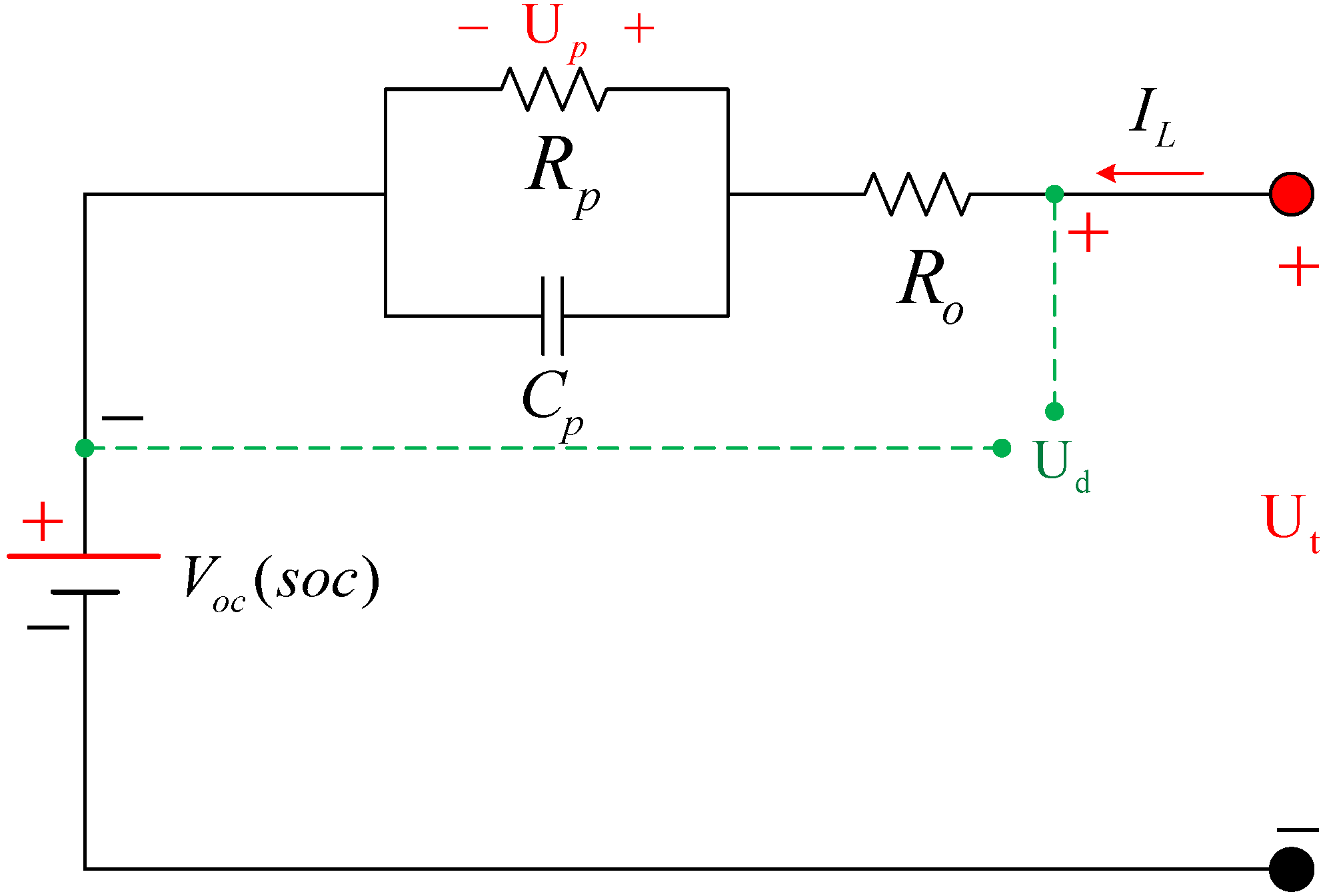
2.1. Auto Regressive Exogenous (ARX) Battery Model
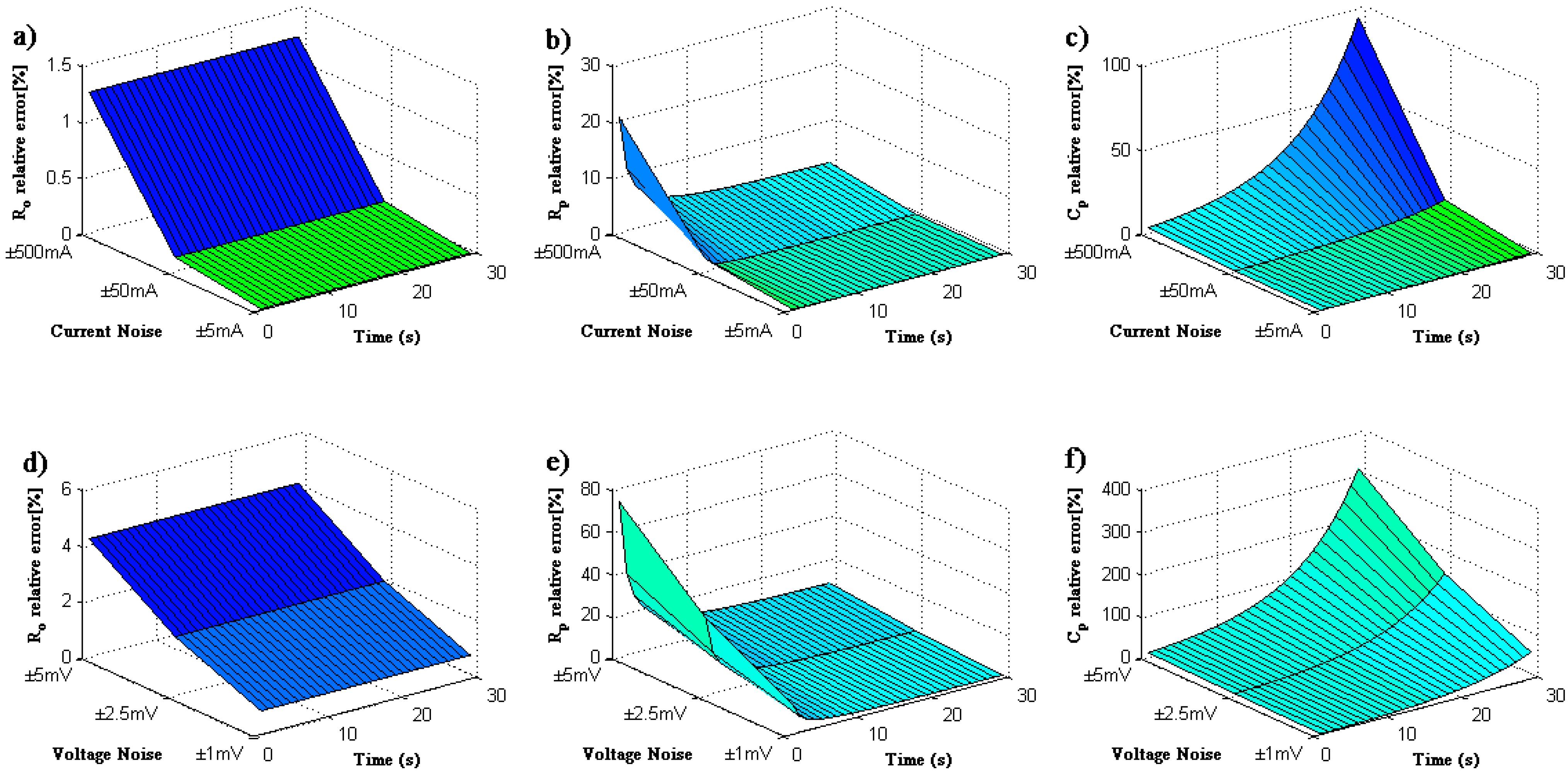
2.2. Perturbation Analysis of Measurement Uncertainty
| Item | Magnitude of noise | Parameter relative error (%) @ 0.2C | Parameter relative error (%) @ 1.0C | ||||
|---|---|---|---|---|---|---|---|
| Ro | Rp | Cp | Ro | Rp | Cp | ||
| Current noise | δIL = ±5 mA | 0.0625 | 0.1513 | 0.1411 | 0.0125 | 0.0303 | 0.0282 |
| δIL = ±50 mA | 0.6224 | 1.5058 | 1.4111 | 0.1249 | 0.3024 | 0.2822 | |
| δIL = ±500 mA | 6.000 | 14.407 | 14.111 | 1.2397 | 2.9966 | 2.8223 | |
| Voltage noise | δUt = ±1 mV | 4.1667 | 8.5613 | 9.2046 | 0.8333 | 1.7123 | 1.8815 |
| δUt = ±2.5 mV | 10.416 | 21.403 | 23.518 | 2.0833 | 4.2806 | 4.7038 | |
| δUt = ±5 mV | 20.833 | 42.806 | 47.037 | 4.1667 | 8.5613 | 9.4076 | |
2.3. Model Stability Analysis
| Sampling Ts (s) | Parameter variation | Stability analysis | |||
|---|---|---|---|---|---|
| a1 | b0 | b1 | Pole | Zero | |
| 1 | 0.88235 | 0.00205 | −0.00170 | 0.88235 | 0.82857 |
| 0.5 | 0.93939 | 0.00203 | −0.00184 | 0.93939 | 0.91044 |
| 0.2 | 0.97530 | 0.00201 | −0.00193 | 0.97530 | 0.96319 |
| 0.1 | 0.98757 | 0.00200 | −0.00196 | 0.98757 | 0.98142 |
| 0.02 | 0.99750 | 0.00200 | −0.00199 | 0.99750 | 0.99625 |
2.4. Parametric Sensitivity Analysis
| Item | Sensitivity | a1 | b0 | b1 |
|---|---|---|---|---|
| Sample @ Ts = 1 s | Ro | −0.4688 | 0.5469 | 0.4531 |
| Rp | 23.4374 | 16.4062 | −15.4062 | |
| Cp | −15.4688 | −16.4063 | 15.4063 | |
| Sample @ Ts = 0.5 s | Ro | −0.4844 | 0.5234 | 0.4766 |
| Rp | 47.4687 | 32.4531 | −31.4531 | |
| Cp | −31.4844 | −32.4531 | 31.4531 | |
| Sample @ Ts = 0.1 s | Ro | −0.4969 | 0.5047 | 0.4953 |
| Rp | 239.4938 | 160.4906 | −159.4906 | |
| Cp | −159.4969 | −160.4906 | 159.4906 | |
| Sample @ Ts = 0.02 s | Ro | −0.4994 | 0.5009 | 0.4991 |
| Rp | 1199.5 | 800.4981 | −799.4981 | |
| Cp | −799.4994 | −800.4981 | 799.4981 |
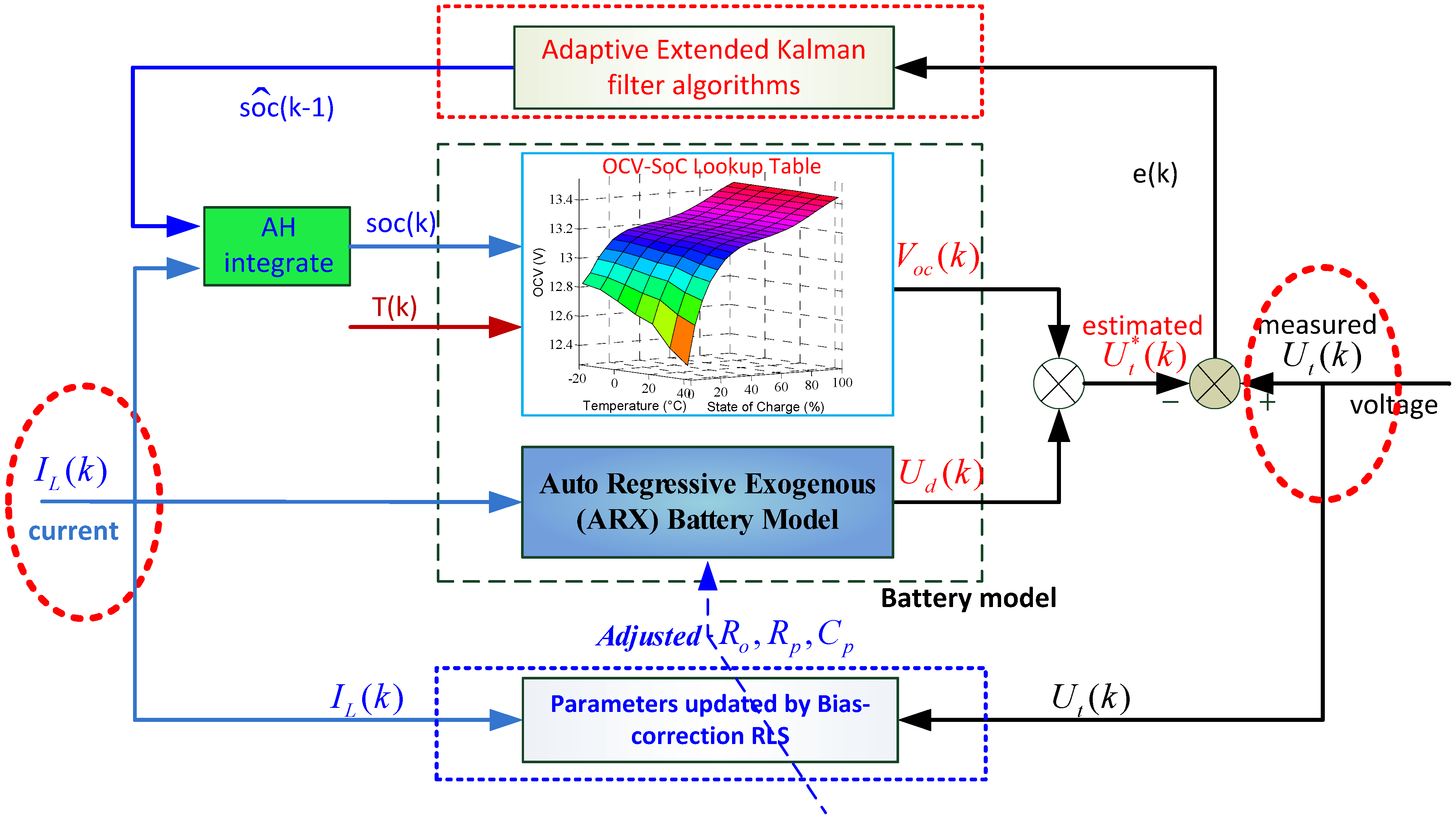
3. Adaptive Extended Kalman Filter Algorithm
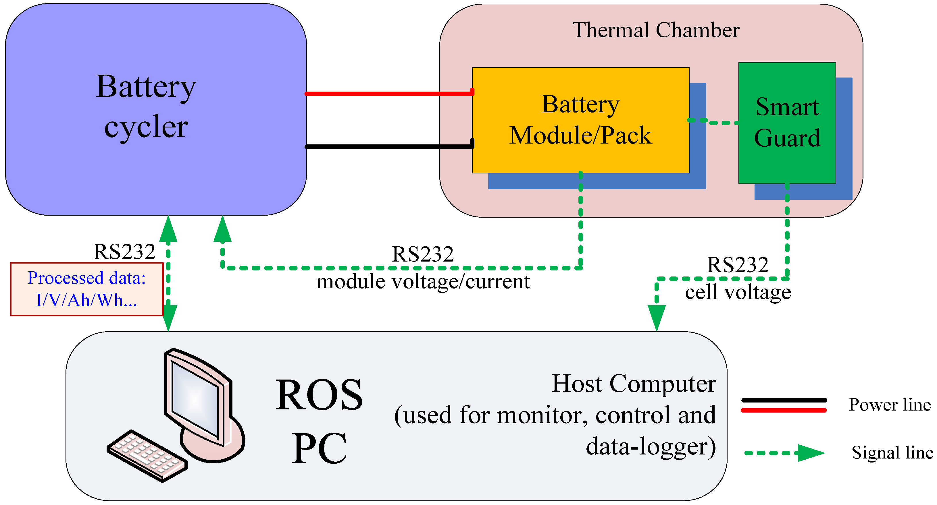
4. Experimental Setup

| Type | Rated capacity | Rated energy | Maximum current | Rated voltage | Upper voltage | Lower voltage |
|---|---|---|---|---|---|---|
| LiFePO4 | 60 A h | 192 W h | 3C, 180 A | 3.20 V | 3.65 V | 2.10 V |

5. Simulation and Discussion
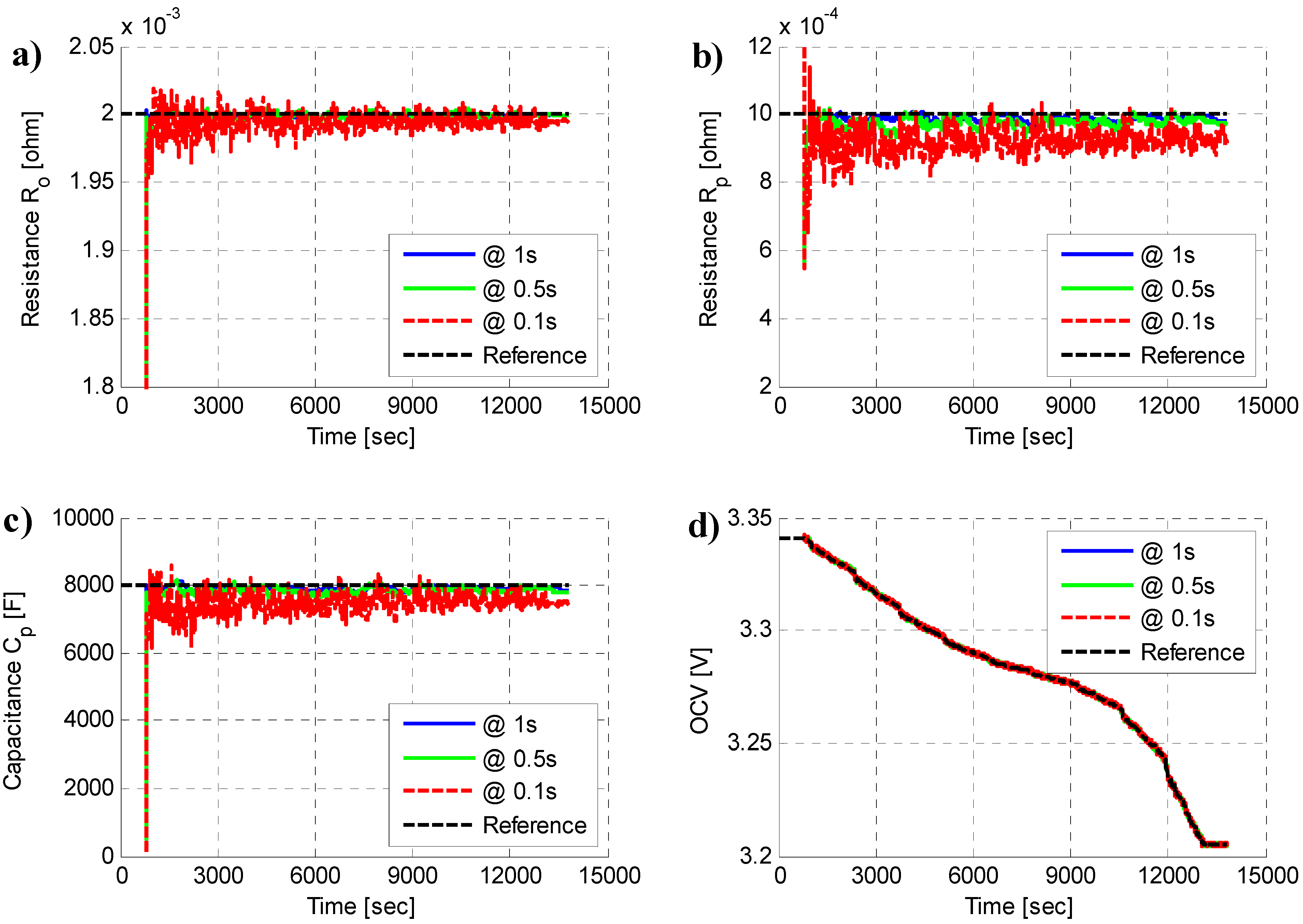
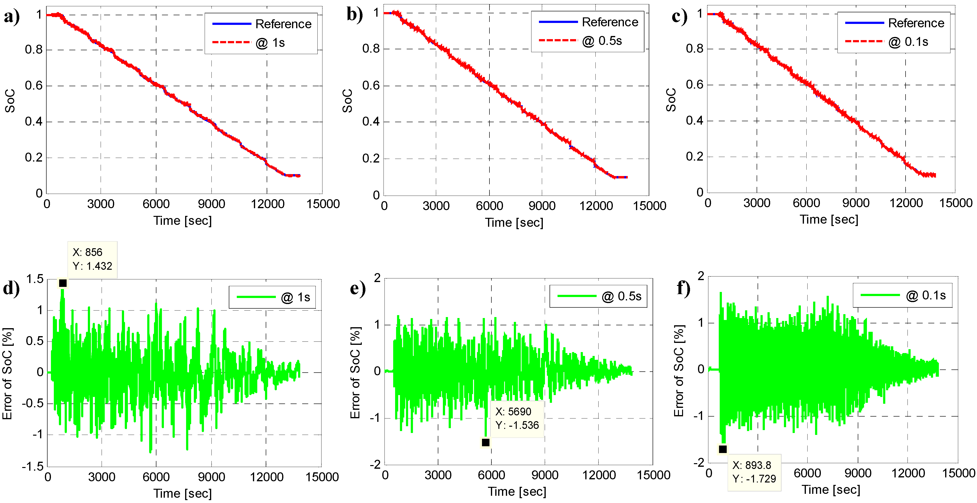
5.1. Sampling Period Effect


| Item | Sample @ 1.0s | Sample @ 0.5s | Sample @ 0.1s | |||||||||
|---|---|---|---|---|---|---|---|---|---|---|---|---|
| Parameters | Ro | Rp | Cp | SoC | Ro | Rp | Cp | SoC | Ro | Rp | Cp | SoC |
| Maximum error (%) | 0.24 | 3.38 | 2.66 | 1.43 | 0.38 | 7.33 | 5.09 | 1.53 | 1.90 | 21.9 | 23.8 | 1.72 |
| RMSE (%) | 0.06 | 1.34 | 1.23 | 0.33 | 0.11 | 2.55 | 2.10 | 0.34 | 0.38 | 8.39 | 7.31 | 0.36 |
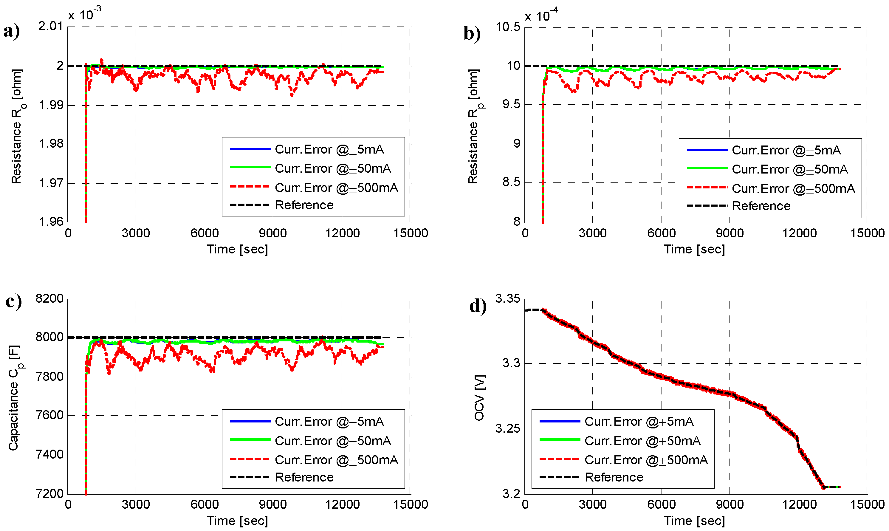
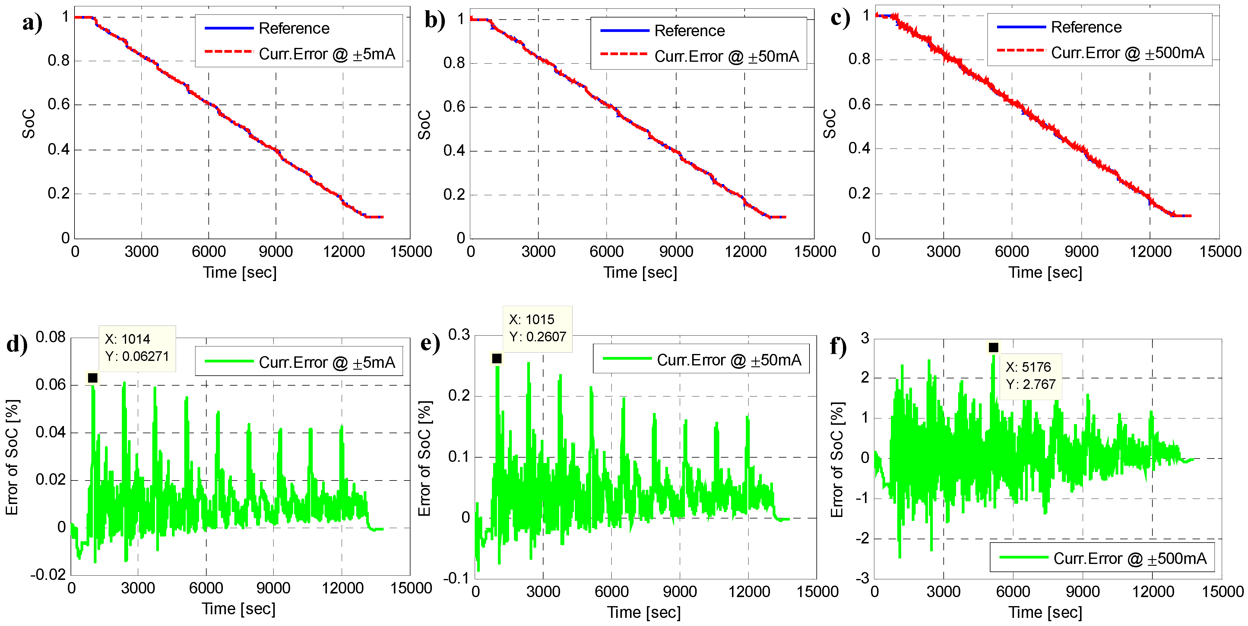
5.2. Current Sensor Accuracy Effect
| Company and product name | LEM DHAB S/25 (Geneva, Switzerland) | LEM LA100-P (Geneva, Switzerland) | Allegro, ACS758 LCB-100B-PSF-T (Worcester, MA, USA) |
|---|---|---|---|
| Transducer type | Open loop | Closed loop | Closed loop |
| Supply voltage | 5 V | 5 V | 3.3 V or 5 V |
| Primary current Ip | ±25 A for ch1; ±200 A for ch2 | ±100 A | ±100 A |
| Output voltage Vsn | 0.25–4.75 V | - | Vref ±2 V |
| Overall accuracy @Ip, T = 25 °C | ±4%, ±500 mA | ±0.45%, ±50 mA | ±2.4%, ±150 mA |
| Linearity error | <±1% | <±0.15% | <±1.25% |
| Operation temperance | −40.125 °C | −40.85 °C | −40.150 °C |
| Response time | <25 ms | <1 μs | <4 μs |

| Item | Current accuracy: ±5 mA | Current accuracy: ±50 mA | Current accuracy: ±500 mA | |||||||||
|---|---|---|---|---|---|---|---|---|---|---|---|---|
| Parameters | Ro | Rp | Cp | SoC | Ro | Rp | Cp | SoC | Ro | Rp | Cp | SoC |
| Maximum error (%) | 0.02 | 0.71 | 0.50 | 0.06 | 0.04 | 0.69 | 0.45 | 0.26 | 0.39 | 3.53 | 2.43 | 2.76 |
| RMSE (%) | 0.01 | 0.33 | 0.25 | 0.01 | 0.01 | 0.33 | 0.25 | 0.06 | 0.15 | 1.50 | 1.15 | 0.54 |

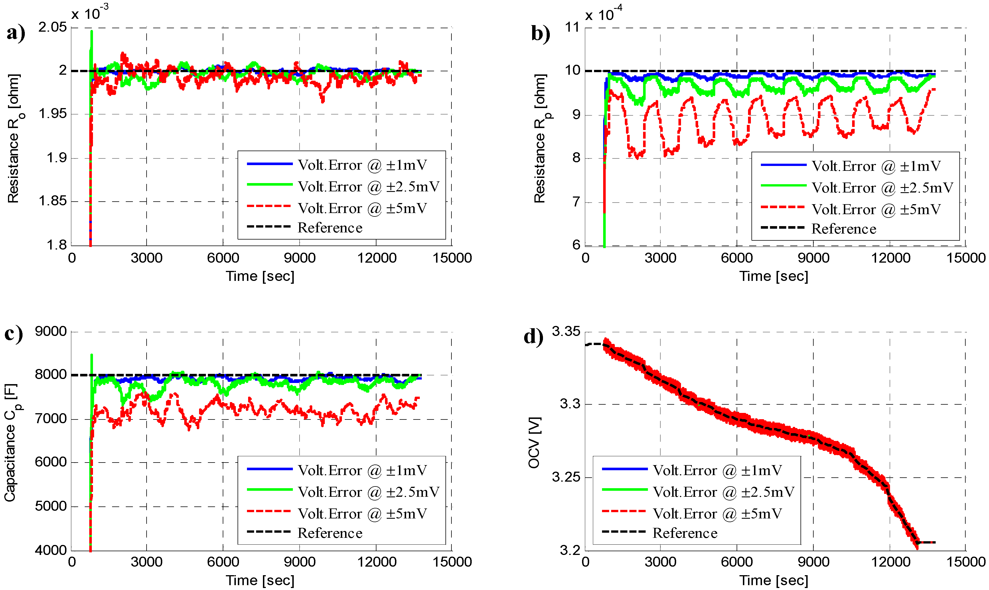
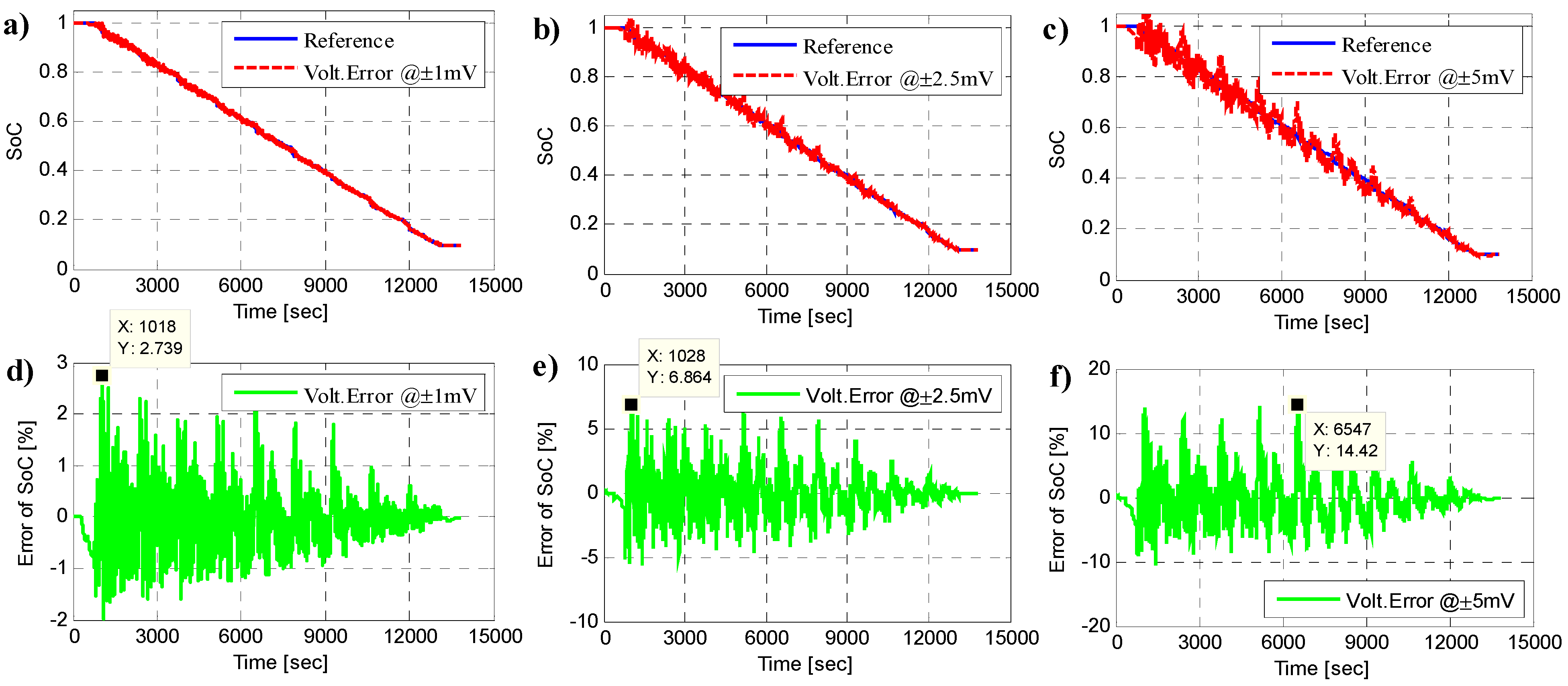
5.3. Voltage Sensor Accuracy Effect
| Company and product name | Linear Technology Co. LTC6802 (Milpitas, CA, USA) | Texas Instrument Co. bq76PL536 (Dallas, TX, USA) | Maxim Co. MAX11068 (San Jose, CA, USA) |
|---|---|---|---|
| Voltage meas. channels | 12 | 6 | 12 |
| AD resolution (Bit) | 16 | 14 | 12 |
| AD conversion time | 57 μs | 6 μs | 10 μs |
| Typical voltage accuracy | ±1.2 mV | ±3.0 mV | ±12.5 mV |
| Maximum voltage accuracy | ±8.3 mV | ±18.0 mV | ±50.0 mV |
| Operating temp. range | −40 °C to +85 °C | −40 °C to +85 °C | −40 °C to +105 °C |
| Cell balancing | 12 channels | 6 channels | 12 channels |
| Input voltage range (V) | 0–75 | 0–30 | 6–72 |
| Item | Voltage accuracy: ±1 mV | Voltage accuracy: ±2.5 mV | Voltage accuracy: ±5 mV | |||||||||
|---|---|---|---|---|---|---|---|---|---|---|---|---|
| Parameters | Ro | Rp | Cp | SoC | Ro | Rp | Cp | SoC | Ro | Rp | Cp | SoC |
| Maximum error (%) | 0.33 | 2.51 | 2.36 | 2.73 | 1.08 | 7.79 | 8.52 | 6.86 | 1.79 | 20.74 | 15.9 | 14.42 |
| RMSE (%) | 0.11 | 1.08 | 1.07 | 0.54 | 0.34 | 3.64 | 2.88 | 1.64 | 0.51 | 12.01 | 10.11 | 3.54 |
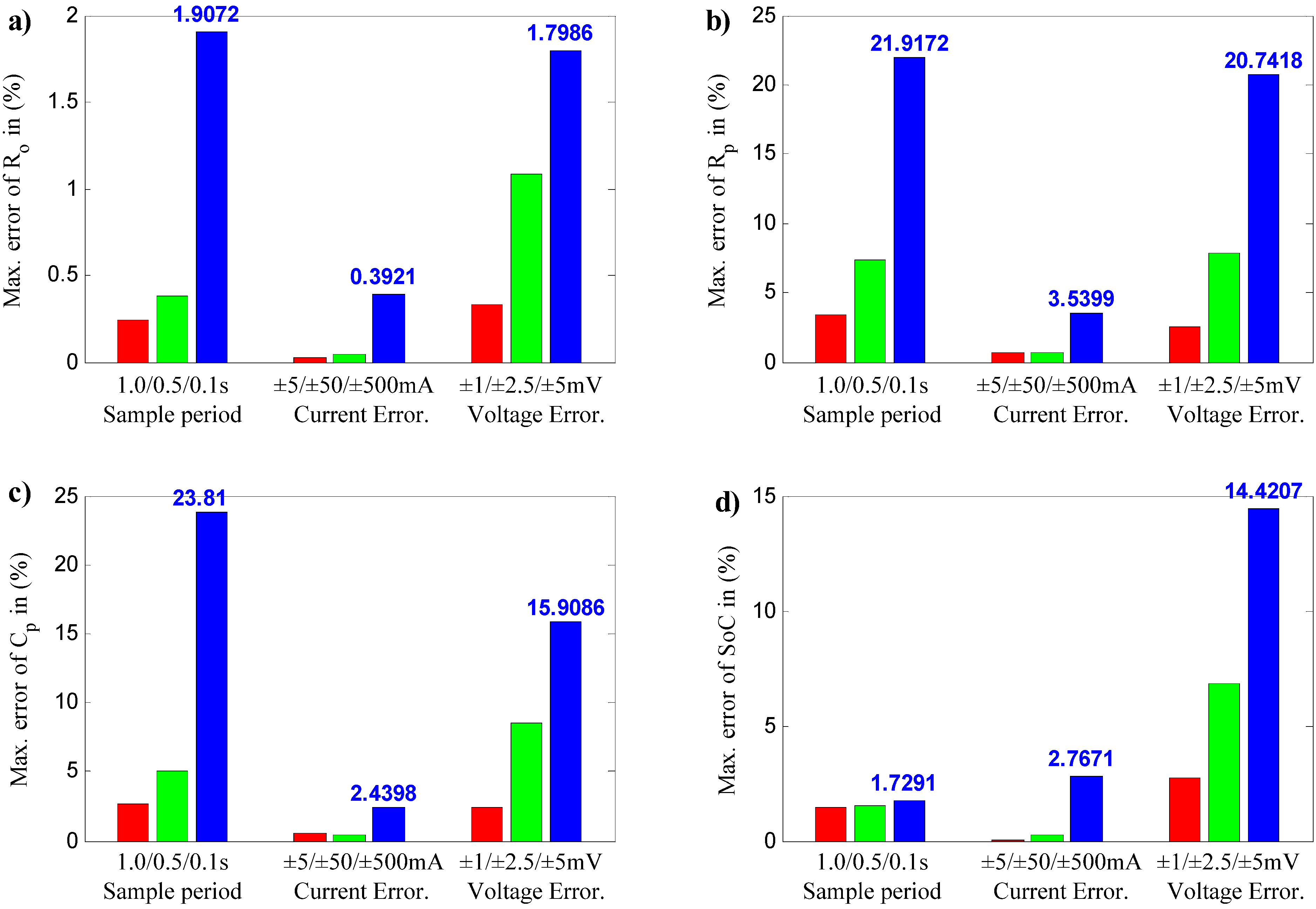
5.4. Results Comparison and Discussion
- (1)
- The variation of sampling periods (0.1–1 s) has a significant impact on parameter estimation accuracy. Specifically, the sampling time has a relatively small effect to estimate the ohmic resistance Ro, with the maximum error of 2%. However, the sampling time presents the significant influence for polarization resistance Rp and polarization capacitance Cp with the maximum error of 23%. This result is verification of the previous parameter sensitivity analysis, which means the raised parameter sensitivity of Rp and Cp will be more sensitive to external perturbations. Therefore, an accurate estimate of the Rp and Cp will encounter greater difficulty. On the other hand, the variation of sampling rate has a less significant effect on the SoC estimation error. Therefore, changing the sampling time is not the optimal choice to obtain improved estimation accuracy of the SoC.
- (2)
- The variation of current sensor precisions (±5/±50/±500 mA) shows little influence for model parameters estimation. For instance, when the current sensor accuracy is ±500 mA, the maximum error of Rp and Cp is about 3.5% and the maximum error of SoC is about 2.76%. Therefore, to restrict the estimation accuracy of the model parameters and SoC, the current sensor accuracy is recommended to be lesser than ±50 mA.
- (3)
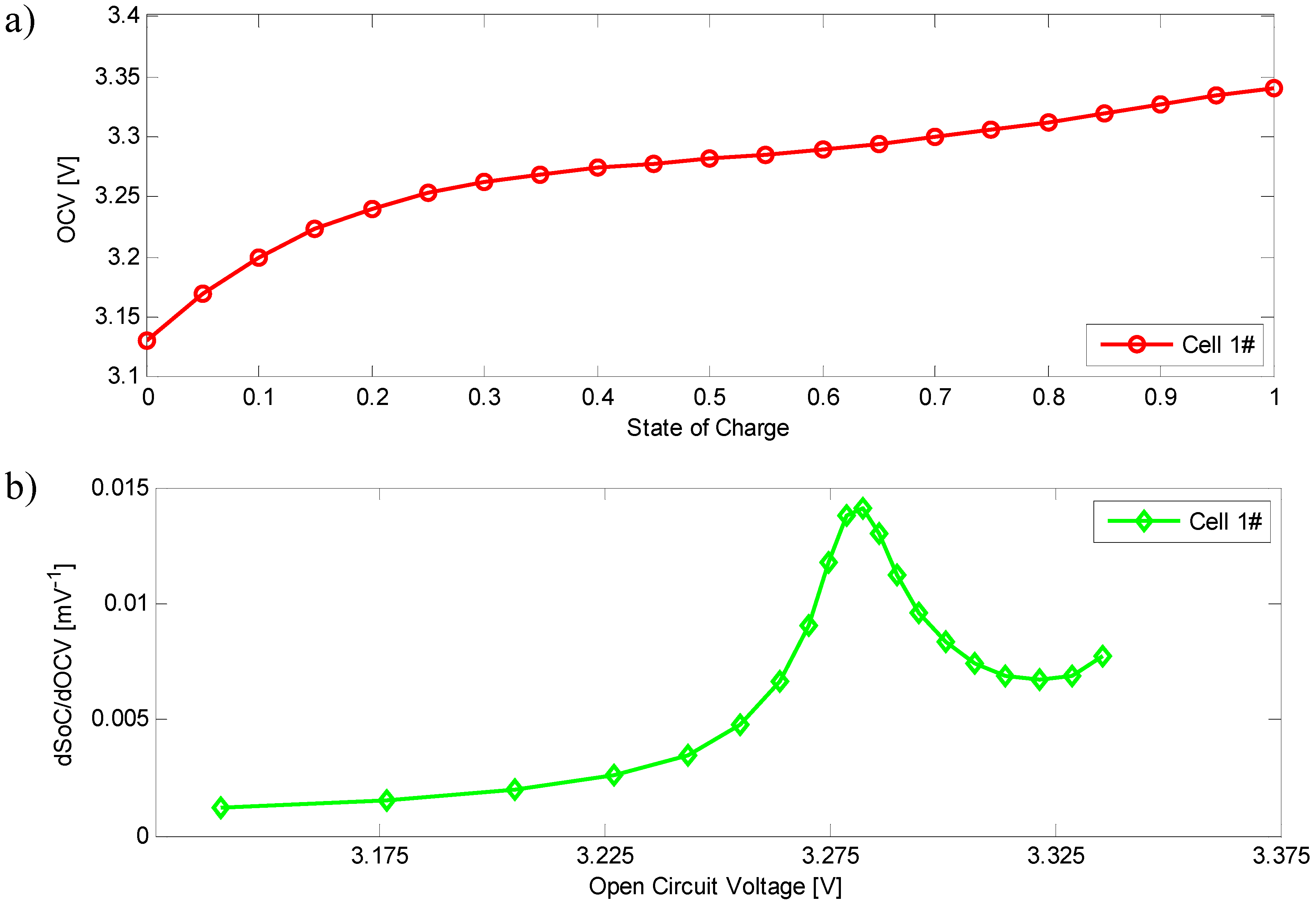
- The variation of voltage sensor precisions (±1/±2.5/±5 mV) has significant impact both on model parameter estimation and on SoC estimation. When the voltage accuracy is ±5 mV, the maximum estimation error of Ro, Rp and Cp is 1.79%, 20.74% and 15.90%, respectively. It reveals that the error of Ro is acceptable, while the error of Rp and Cp is hardly acceptable. As the voltage accuracy decreases to ±1 mV, the maximum estimation error of Ro, Rp and Cp is in the acceptable range of 0.33%, 2.51% and 2.36%. For the SoC estimation, the maximum SoC error increases from 2.73%, 6.86% to 14.42%, as the voltage sensor accuracy ascends from ±1 mV, ±2.5 mV to ±5 mV. Therefore, to ensure an accurate SoC estimation (<5%), the voltage sensor precision should be less than ±2 mV. This conclusion can also be drawn from the ICA result.
- (4)
- The weighted importance of factors on parameters and SoC estimation can be sorted as (by descending order): voltage sensor accuracy > sampling period > current sensor accuracy based on the above comparison.
- (a)
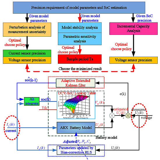
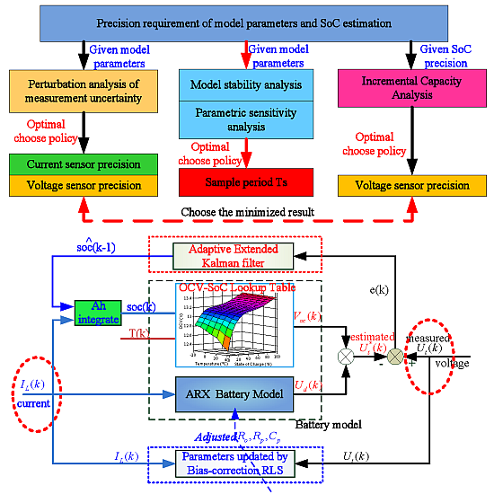
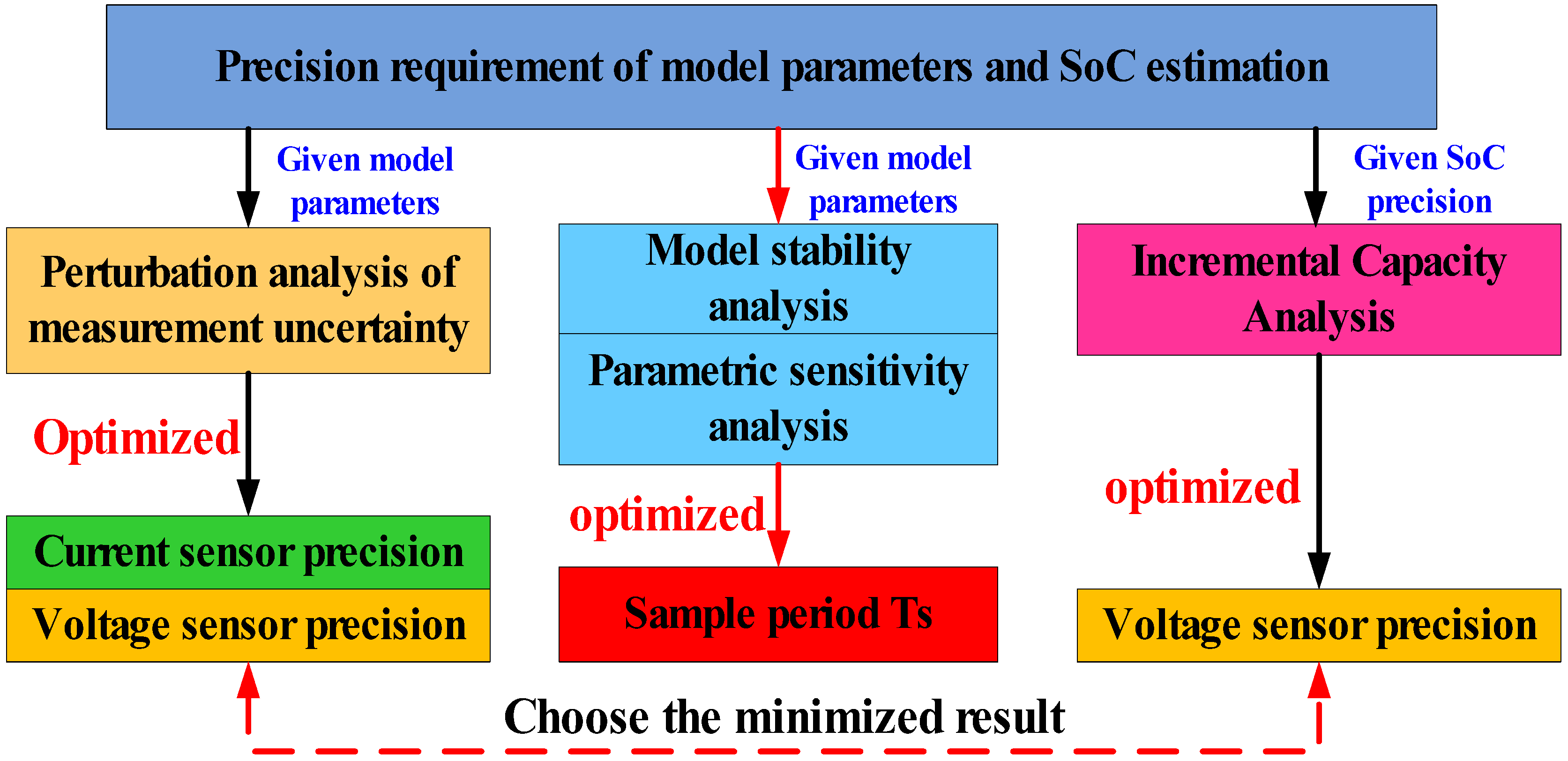
- Firstly assess the parameters of battery system, such as Ro, Rp, Cp and capacity, then conduct the perturbation analysis with the Equations (9)–(11) according to the precision requirement of model parameters. The optimized current/voltage sensor precision could be computed.
- (b)
- About the given SoC precision requirement, the user can calculate the voltage precision with the ICA. Take this research for example: If the minimal SoC estimation precision is limited as 1.5%, our voltage sensor precision could be calculated as 1.034 mV with the ICA result in Figure 5.
- (c)
- Compare the voltage precision in Steps (a) and (b), then choose the minimized result. If the minimized result is from Step (a), re-compute Step (a) again to update the current sensor precision.
- (d)
- About the given model parameters, the user can conduct the model stability analysis and parametric sensitivity analysis. Then the threshold of time sampling period Ts could be gain. The optimized time sampling period Ts could be selected in a tradeoff way by considering the model stability, parametric sensitivity, system-sampling precision and the hardware runtime.
6. Conclusions
- (1)
- The model stability and parametric sensitivity have been analyzed under different sampling periods Ts (0.02, 0.1, 0.2, 0.5 and 1 s). The results reveal that the increase of sampling period Ts will be beneficial to the model stability and parameter identifiability. From an engineering viewpoint, it is recommended to restrict the eigenvalues of the ARX model within a range of 0–0.95. That is, Ts should be larger than one threshold, such as Ts ≥ 0.5 s.
- (2)
- The variation of sampling periods (0.1–1 s), has a significant impact on parameter estimation accuracy but a less significant effect on the SoC estimation error. Therefore, to improve the estimation accuracy of the SoC, it is not optimal to change the sampling time.
- (3)
- The variation of current sensor precision (±5/±50/±500 mA) shows little influence for model parameters and SoC estimation. To restrict the estimation accuracy of the model parameters and SoC, the current sensor accuracy is recommended to be less than ±50 mA.
- (4)
- The variation of voltage sensor precision (±1/±2.5/±5 mV) has significant impact on both the model parameter estimation and SoC estimation. To ensure the SoC estimation accuracy (<5%), the voltage sensor accuracy should be less than ±2 mV.
- (5)
- According to the parameter variation analysis under the perturbation of current/voltage measurement uncertainty, the weighted importance of factors on parameter and SoC estimation can be sorted as (by descending order): voltage sensor accuracy > sampling period > current sensor accuracy.
Acknowledgments
Author Contributions
Conflicts of Interest
References
- He, H.; Xiong, R.; Zhang, X.; Sun, F.; Fan, J. State-of-charge estimation of the lithium-ion battery using an adaptive extended Kalman filter based on an improved thevenin model. IEEE Trans. Veh. Technol. 2011, 60, 1461–1469. [Google Scholar]
- He, Z.; Gao, M.; Wang, C.; Wang, L.; Liu, Y. Adaptive state of charge estimation for Li-ion batteries based on an unscented Kalman filter with an enhanced battery model. Energies 2013, 6, 4134–4151. [Google Scholar] [CrossRef]
- Xing, Y.; He, W.; Pecht, M.; Tsui, K.L. State of charge estimation of lithium-ion batteries using the open-circuit voltage at various ambient temperatures. Appl. Energy 2014, 113, 106–115. [Google Scholar] [CrossRef]
- Wang, Y.; Zhang, C.; Chen, Z. A method for joint estimation of state-of-charge and available energy of LiFePO4 batteries. Appl. Energy 2014, 135, 81–87. [Google Scholar] [CrossRef]
- Liu, X.; Wu, J.; Zhang, C.; Chen, Z. A method for state of energy estimation of lithium-ion batteries at dynamic currents and temperatures. J. Power Sources 2014, 270, 151–157. [Google Scholar] [CrossRef]
- Xiong, R.; Sun, F.; Chen, Z.; He, H. A data-driven multi-scale extended Kalman filtering based parameter and state estimation approach of lithium-ion olymer battery in electric vehicles. Appl. Energy 2014, 113, 463–476. [Google Scholar] [CrossRef]
- Xiong, R.; Sun, F.; Gong, X.; Gao, C. A data-driven based adaptive state of charge estimator of lithium-ion polymer battery used in electric vehicles. Appl. Energy 2014, 113, 1421–1433. [Google Scholar] [CrossRef]
- Dai, H.; Wei, X.; Sun, Z.; Wang, J.; Gu, W. Online cell SOC estimation of Li-ion battery packs using a dual time-scale Kalman filtering for EV applications. Appl. Energy 2012, 95, 227–237. [Google Scholar] [CrossRef]
- Zhong, L.; Zhang, C.; He, Y.; Chen, Z. A method for the estimation of the battery pack state of charge based on in-pack cells uniformity analysis. Appl. Energy 2014, 113, 558–564. [Google Scholar] [CrossRef]
- Liu, X.; Chen, Z.; Zhang, C.; Wu, J. A novel temperature-compensated model for power Li-ion batteries with dual-particle-filter state of charge estimation. Appl. Energy 2014, 123, 263–272. [Google Scholar] [CrossRef]
- Hu, X.; Li, S.; Peng, H.; Sun, F. Charging time and loss optimization for linmc and LiFePO4 batteries based on equivalent circuit models. J. Power Sources 2013, 239, 449–457. [Google Scholar] [CrossRef]
- Xiong, R.; Gong, X.; Mi, C.C.; Sun, F. A robust state-of-charge estimator for multiple types of lithium-ion batteries using adaptive extended Kalman filter. J. Power Sources 2013, 243, 805–816. [Google Scholar] [CrossRef]
- Plett, G.L. Extended Kalman filtering for battery management systems of LiPB-based HEV battery packs: Part 1. Background. J. Power Sources 2004, 134, 252–261. [Google Scholar] [CrossRef]
- Plett, G.L. Extended Kalman filtering for battery management systems of LiPB-based HEV battery packs: Part 2. Modeling and identification. J. Power Sources 2004, 134, 262–276. [Google Scholar] [CrossRef]
- Plett, G.L. Extended Kalman filtering for battery management systems of LiPB-based HEV battery packs: Part 3. State and parameter estimation. J. Power Sources 2004, 134, 277–292. [Google Scholar] [CrossRef]
- Yuan, S.; Wu, H.; Yin, C. State of charge estimation using the extended Kalman filter for battery management systems based on the arx battery model. Energies 2013, 6, 444–470. [Google Scholar] [CrossRef]
- Han, J.; Kim, D.; Sunwoo, M. State-of-charge estimation of lead-acid batteries using an adaptive extended Kalman filter. J. Power Sources 2009, 188, 606–612. [Google Scholar] [CrossRef]
- Sun, F.; Hu, X.; Zou, Y.; Li, S. Adaptive unscented Kalman filtering for state of charge estimation of a lithium-ion battery for electric vehicles. Energy 2011, 36, 3531–3540. [Google Scholar] [CrossRef]
- Santhanagopalan, S.; White, R.E. State of charge estimation using an unscented filter for high power lithium ion cells. Int. J. Energy Res. 2010, 34, 152–163. [Google Scholar] [CrossRef]
- Shao, S.; Bi, J.; Yang, F.; Guan, W. On-line estimation of state-of-charge of Li-ion batteries in electric vehicle using the resampling particle filter. Transp. Res. Part D 2014, 32, 207–217. [Google Scholar] [CrossRef]
- Gao, M.; Liu, Y.; He, Z. Battery State of Charge Online Estimation Based on Particle Filter. In Preoceeeings of the 2011 4th International Congress on Image and Signal Processing (CISP), Shanghai, China, 15–17 October 2011; IEEE: New York, NY, USA, 2011; pp. 2233–2236. [Google Scholar]
- Hu, X.; Sun, F.; Zou, Y. Estimation of state of charge of a lithium-ion battery pack for electric vehicles using an adaptive luenberger observer. Energies 2010, 3, 1586–1603. [Google Scholar] [CrossRef]
- Kim, I.-S. The novel state of charge estimation method for lithium battery using sliding mode observer. J. Power Sources 2006, 163, 584–590. [Google Scholar] [CrossRef]
- Xia, B.; Chen, C.; Tian, Y.; Sun, W.; Xu, Z.; Zheng, W. A novel method for state of charge estimation of lithium-ion batteries using a nonlinear observer. J. Power Sources 2014, 270, 359–366. [Google Scholar] [CrossRef]
- Zhang, X.; Mi, C. Vehicle Power Management: Modeling, Control and Optimization; Springer: Berlin/Heidelberg, Germany, 2011. [Google Scholar]
- Hu, X.; Sun, F.; Zou, Y.; Peng, H. Online Estimation of an Electric Vehicle Lithium-Ion Battery Using Recursive Least Squares with Forgetting. In Preoceeeings of the American Control Conference (ACC), San Francisco, CA, USA, 29 June–1 July 2011; IEEE: New York, NY, USA, 2011; pp. 935–940. [Google Scholar]
- Feng, D.; Tongwen, C.; Li, Q. Bias compensation based recursive least-squares identification algorithm for MISO systems. IEEE Trans. Circuits Syst. II Express Briefs 2006, 53, 349–353. [Google Scholar] [CrossRef]
- Wu, H.; Yuan, S.; Zhang, X.; Yin, C.; Ma, X. Model parameter estimation approach based on incremental analysis for lithium-ion batteries without using open circuit voltage. J. Power Sources 2015, 287, 108–118. [Google Scholar] [CrossRef]
- Xiong, R.; He, H.; Sun, F.; Liu, X.; Liu, Z. Model-based state of charge and peak power capability joint estimation of lithium-ion battery in plug-in hybrid electric vehicles. J. Power Sources 2013, 229, 159–169. [Google Scholar] [CrossRef]
- Lem—Current Tranducer, Voltage Transducer, Sensor, Power Measurement. Available online: http://www.lem.com/ (accessed on 26 June 2015).
- Allegro MicroSystems LLC. Available online: http://www.allegromicro.com/ (accessed on 26 June 2015).
- Linear Technology—Home Page. Available online: http://www.linear.com/index.php (accessed on 26 June 2015).
- Analog, Embedded Processing, Semiconductor Company, Texas Instruments—TI.Com. Available online: http://www.ti.com/ (accessed on 26 June 2015).
- Maxim Integrated. Analog, Linear, and Mixed-Signal Devices from Maxim. Available online: http://www.maximintegrated.com/en.html (accessed on 26 June 2015).
© 2015 by the authors; licensee MDPI, Basel, Switzerland. This article is an open access article distributed under the terms and conditions of the Creative Commons Attribution license (http://creativecommons.org/licenses/by/4.0/).
Share and Cite
Yuan, S.; Wu, H.; Ma, X.; Yin, C. Stability Analysis for Li-Ion Battery Model Parameters and State of Charge Estimation by Measurement Uncertainty Consideration. Energies 2015, 8, 7729-7751. https://doi.org/10.3390/en8087729
Yuan S, Wu H, Ma X, Yin C. Stability Analysis for Li-Ion Battery Model Parameters and State of Charge Estimation by Measurement Uncertainty Consideration. Energies. 2015; 8(8):7729-7751. https://doi.org/10.3390/en8087729
Chicago/Turabian StyleYuan, Shifei, Hongjie Wu, Xuerui Ma, and Chengliang Yin. 2015. "Stability Analysis for Li-Ion Battery Model Parameters and State of Charge Estimation by Measurement Uncertainty Consideration" Energies 8, no. 8: 7729-7751. https://doi.org/10.3390/en8087729