Abstract
Automatically identifying the new equipment after its integration and adjusting operation strategy to realize “plug and play” functionality are becoming essential for micro-grid operations. In order to improve and perfect the micro-grid “plug and play” function with the increased amount of equipment with different information protocols and more diverse system applications, this paper presents a solution for adaptive micro-grid operation based on IEC 61850, and proposes the design and specific implementation methods of micro-grid “plug and play” function and system operation mode conversion in detail, by using the established IEC 61850 information model of a micro-grid. Actual operation tests based on the developed IED and micro-grid test platform are performed to verify the feasibility and validity of the proposed solution. The tests results show that the solution can automatically identify the IEC 61850 information model of equipment after its integration, intelligently adjust the operation strategies to adapt to new system states and achieves a reliable system operation mode conversion.
1. Introduction
Distributed energy resources (DERs), such as clean renewable energy and combined heat and power (CHP), are becoming a hot issue in current energy study. As a kind of organizational DER form with broad development prospects [1], micro-grids can effectively manage the wind power (WP), photovoltaic system (PV), energy storage devices, and controllable loads, and provide two kinds of operation mode, including autonomous mode and grid-connected mode. Due to their energy management and operation optimization technology, micro-grids can be used to enhance the reliability of power supplies, realize efficient energy utilization, and improve the renewable energy integration capability [2,3,4].
At present, there are many types of equipment in micro-grids, including DERs, monitoring devices, and protection devices with different information interfaces and communication protocols. Influenced by some uncertain factors such as complicated operation scheduling, and intermittent fluctuations in renewable energy power, these equipment may be put into operation or shut down frequently. If a large amount of equipment is put into operation with multiple protocols, supervisory control and data acquisition systems (SCADAs)/energy management systems (EMSs) cannot automatically identify the device characteristics, or adjust operation strategies to adapt to new system states. Therefore micro-grids need a “plug and play” function to reduce the time of system configuration during the equipment integration to improve the system integration efficiency [5]. On the other hand, micro-grids may convert their operation modes, such as conversion from the autonomous mode to the grid-connected mode and vice versa according to the operation requirements, and need fast and reliable control of the diverse equipment during the conversion to ensure the stable operation of the micro-grid. Therefore, to establish a standardized information system with “plug and play” functions and rapid information exchange, and further effectively manage the equipment, has positive significance for micro-grid operation.
IEC 61850 adopts the object-oriented modelling technology and flexible communication architecture, and provides a standardized system language, semantics, service, protocol and architecture, to meet the requirements of interoperability and extendibility for a variety of applications [6]. IEC 61850 is becoming an effective solution for information modelling and micro-grid “plug and play” function with reduced complexity and cost of system integration. Besides, due to its real-time data transmission and publish/subscribe mechanism, IEC 61850 can also support the fast control to realize the operation modes conversion of micro-grids. At present, the research around IEC 61850 application in micro-grids provides the related information model and implementation methods of “plug and play” functions for information modelling and information mapping of typical equipment involving PV, fuel cells, WP, and electric vehicles (EVs) [7,8,9], design of intelligent electronic devices (IEDs) as universal gateways in IEC 61850 bay level [10], micro-grid economic scheduling and hierarchical management based on IEC 61850 [11]. Reference [12] presents a plug-and-play cloud solution for next generation DERs, built upon the IEC 61850 standard for easy communication and cooperation between DERs and system operators, and the centralized configuration combined with a “plug and play” behaviour can control and monitor resources with little user interaction. Reference [13] introduces a new communication protocol mapping for IEC 61850 based on the devices’ profiles for web services, to enable vertical automation in energy distribution networks, and the work makes it possible to achieve the “plug and play” capability so that information can be shared on a single network independent from any implementation or manufacturer. Reference [14] develops a new middleware platform for micro-grids integrating the device-level service oriented architecture based on IEC 61850, to significantly facilitate standards-compliant DER integration and micro-grid management, and the middleware mapping presented demonstrates the extensibility of IEC 61850 systems and provides proof-of-concept for “plug and play” DER systems.
However, the current IEC 61850 models have relatively preliminary structures, and cannot yet provide perfect “plug and play” functions for micro-grids which become more and more complex. It is difficult to automatically identify the crucial equipment information and achieve the control adjustment, and a series of system operation strategies including optimal operation, and seamless transition must be manually adjusted instead of automatically adjusted after new DER integration. Considering the complex function and diverse new equipment of micro-grids, their IEC 61850 models and “plug and play” function correspondingly need to be improved, otherwise it will be difficult to implement the system coordination. Therefore, in order to solve this problem, this paper presents a solution for micro-grid operation based on IEC 61850, establishes the information model of typical micro-grid equipment, then elaborates the “plug and play” function and operation mode conversion in detail. Further, the feasibility and validity of the proposed solution are verified by using the developed IED and micro-grid test platform.
This paper is structured as follows: Section 2 outlines the IEC 61850 micro-grid system. Section 3 describes the design of micro-grid “plug and play” functions and operation mode conversion, and their specific implementation methods. Section 4 shows the corresponding experimental results. Conclusions are drawn in Section 5.
2. System Description
The micro-grid system under investigation in this paper is mainly composed of two parts: the information system and the power system, as shown in Figure 1.

Figure 1.
Micro-grid system description.
Figure 1.
Micro-grid system description.
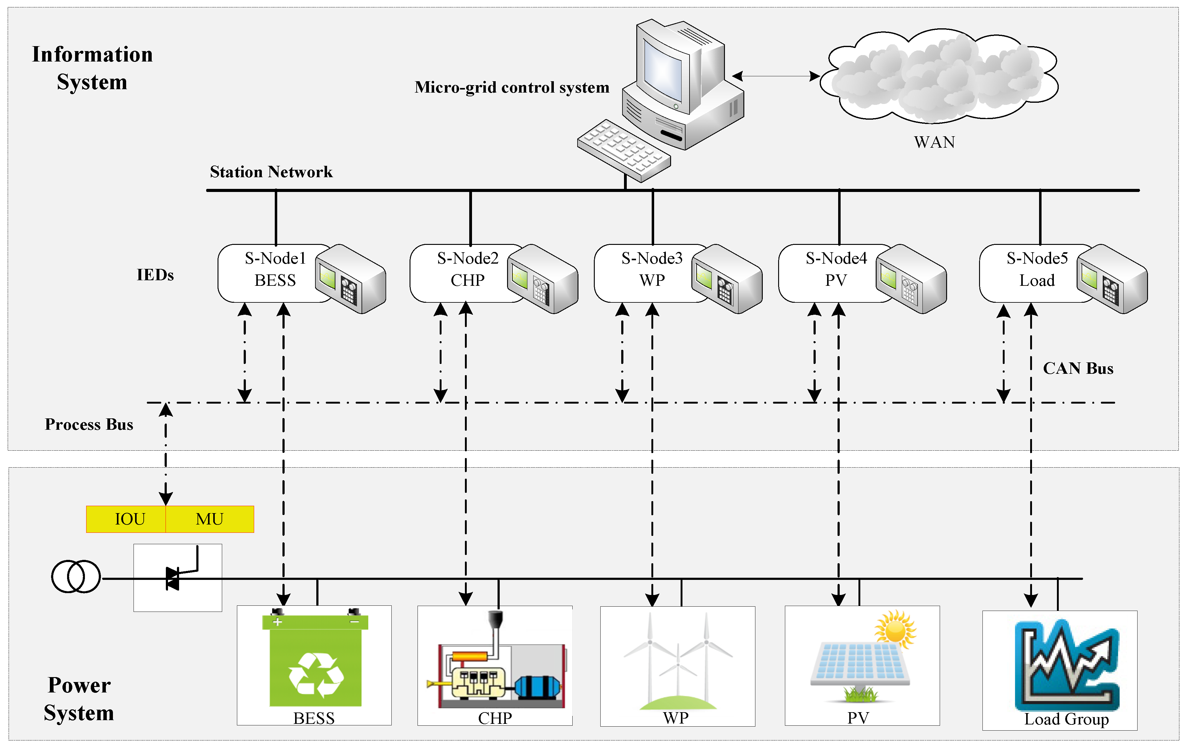
The power system is the physical foundation to realize the micro-grid function, and it is composed of distributed generation (DG) units (such as PV, WP, and CHP), load units, energy storage units, and auxiliary units. According to the controllability of output power, battery energy storage system (BESS) and CHP belong to the schedulable DERs among micro-grid DERs, while, renewable energy sources such as PV and WP belong to the unschedulable DERs due to their uncertainty and power output randomness affected by natural factors. Each DER accesses the micro-grid bus through a circuit breaker or protection switch, as shown in Figure 1, and the micro-grid connects to a utility grid by the point of common connection (PCC) interconnection switch. When the PCC interconnection switch closes, the micro-grid accesses the utility grid and converts to the grid-connected mode. When the switch is open, the micro-grid is separated from the utility grid and converts to the autonomous mode.
According to IEC 61850, the information system of a micro-grid can be divided into station level, bay level, and process level. IEC 61850-7-420 provides the information model and LNs for typical DERs in the process level, including electrical connection points (ECPs), controllers, generators, energy converters, DC converters (such as rectifiers, inverters), and auxiliary systems (such as measurement devices, protection devices) [15]. IEC 61850 7-1, 7-2, 7-3, and 7-4 further provide the model principle [16], ACSI [17], CDC [18], and LNs [19] of physical equipment, respectively. IEC/TR 61850-90-7 gives IEC 61850 object models of inverters for energy storage systems. Based on previously mentioned standards, information modeling of micro-grid equipment in the process level can be achieved.
The bay level is mainly composed of S-Nodes. As shown in Figure 1, each S-Node is an IED, responsible for the information exchange between the station level and process level. On the one hand, the S-Node receives and analyzes the status information and measured values from the process level, and then transmits them to the station level. On the other hand, the S-Node receives and analyzes the controls and settings from the station level, and then transmits them to process level to manage the micro-grid equipment. IEC 61850 7-4 has provided the fundamental LNs for control, monitoring, protection, and other functions, so the S-Node can build the information model according to the requirements of equipment applications.
The station level could be a micro-grid control system, which is responsible for micro-grid operation monitoring, stability control, and energy optimization, and exchanging generation planning and management instructions with a scheduling center. IEC 61850-6 presents the substation configuration language (SCL) and work procedures of IED and configuration tool, and provides the overall framework for micro-grids including equipment in the process level, S-Nodes in the bay level, and a communication system.
Around the three level structure shown in Figure 1, there could be different communication networks:
- (1)
- Station network between station level and bay level: mainly exchanges low-speed or middle-speed messages (such as automatic control and operation power data), files (such as protection events and settings value), and time synchronization messages. Manufacturing message specification (MMS) is the common message.
- (2)
- Process bus between the bay level and equipment which has a 61850 information interface in the process level: mainly exchanges fast-speed messages (such as trip commands and lock instructions) and original data messages (such as voltage and current sampling data). On the other hand, S-Node subscribes the generic object oriented substation event (GOOSE) messages published by intelligent input/output units (IOUs), and sampled values (SV) messages published by merging units (MUs), through the process bus. On the other hand, the S-Node publishes the control commands including locking and tripping using GOOSE messages through the process bus, and accordingly manages the process level equipment.
- (3)
- CAN bus between the bay level and traditional equipment in the process level: provides real-time data communication, and ensures the reliability of data transmissions by its redundancy structure.
3. Design and Implementation of Micro-Grid Operation Based on IEC 61850
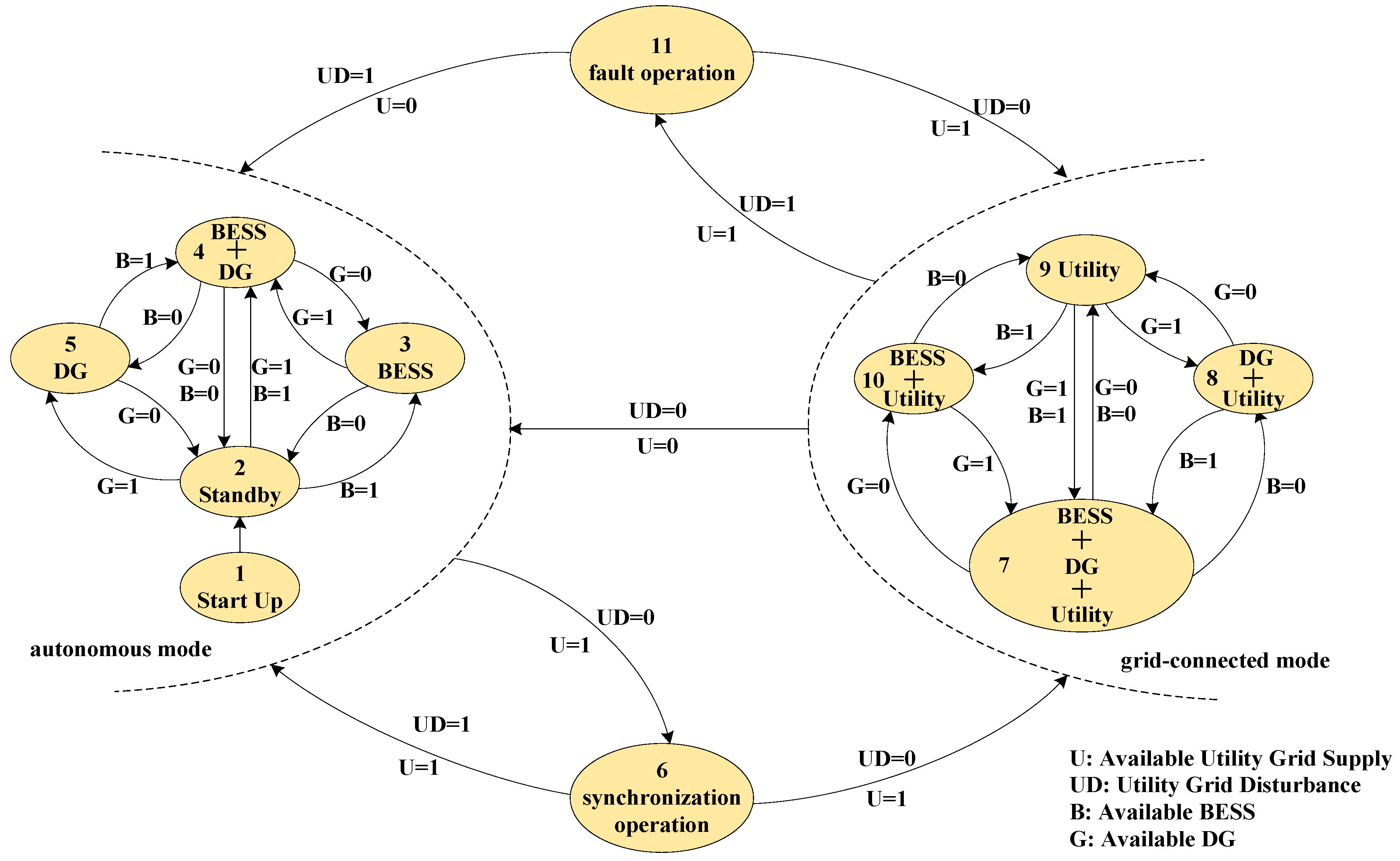
Micro-grids connect with utility grids by PCCs, and can provide several kinds of functions, such as black-start, stable control, and optimal scheduling. The control strategy for each DER varies under the different operation mode or applications, hence the operation state of micro-grid is more complicated, as shown in Figure 2.

Figure 2.
Micro-grid states.
Figure 2.
Micro-grid states.
3.1. Plug and Play
DERs may be put into operation or shut down frequently during micro-grid operation. Hence, their information interfaces need a “plug and play” function to realize fast identification and configuration by the station level when the DER integrates, and to improve the DER integration efficiency. The information model is the important foundation for “plug and play” integration of micro-grid equipment. Equipment’s LNs predefine the groupings of IEC 61850 data objects (DOs) that serve specific equipment functions such as automatic control, monitoring, protection, and measurement, and it can be used as “bricks” to build the complete functions. The typical LNs for micro-grids are established as shown in Figure 3.
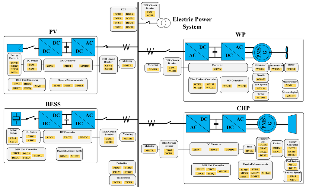
Figure 3.
Conceptual organization of micro-grid LNs.
Figure 3.
Conceptual organization of micro-grid LNs.

A particular physical device of DER could be extracted to the logical devices (LDs) consisting of the relevant LNs to provide specific functions. DER LDs typically include:
- ➢
- ECP: defines the characteristics of the DER plant at the point of electrical connection between the DER and the micro-grid bus, and its LNs should cover corporate characteristics, operational authority, operating mode, status information, economic dispatch parameters, energy and/or ancillary services schedule control, etc.
- ➢
- Generator Unit: describes the generator characteristics of the DER unit with different prime movers depending upon the type of DER device, and its LNs should cover generator operations, generator ratings, advanced generator features, cost, etc.
- ➢
- Exciter: comprises the components of a DER that handle the excitation systems used to start the generator, and its LNs should cover excitation ratings and operations.
- ➢
- DC converter: defines the characteristics of the converter, which converts AC to DC or DC to AC, and its LNs should cover rectifier, inverter, and measurement of intermediate DC, etc.
- ➢
- Energy converter: describes the different primary energy converter characteristics of the DER unit depending upon the type of DER device, and its LNs should cover the photovoltaics system (such as module, array), CHP thermal storage, CHP boiler, etc.
- ➢
- DER unit controller: defines the operational characteristics of a single DER device, regardless of the type of prime mover or generator, and its LNs should cover controller characteristics, controller status, supervisory control, etc.
- ➢
- Auxiliary systems: describes the characteristics of auxiliary systems, and its LNs should cover fuel systems, batteries (such as systems, charger), physical measurements (such as temperature, pressure, heat, meteorological information), electric metering, etc.

Figure 4.
Procedures of “plug and play” integration.
Figure 4.
Procedures of “plug and play” integration.
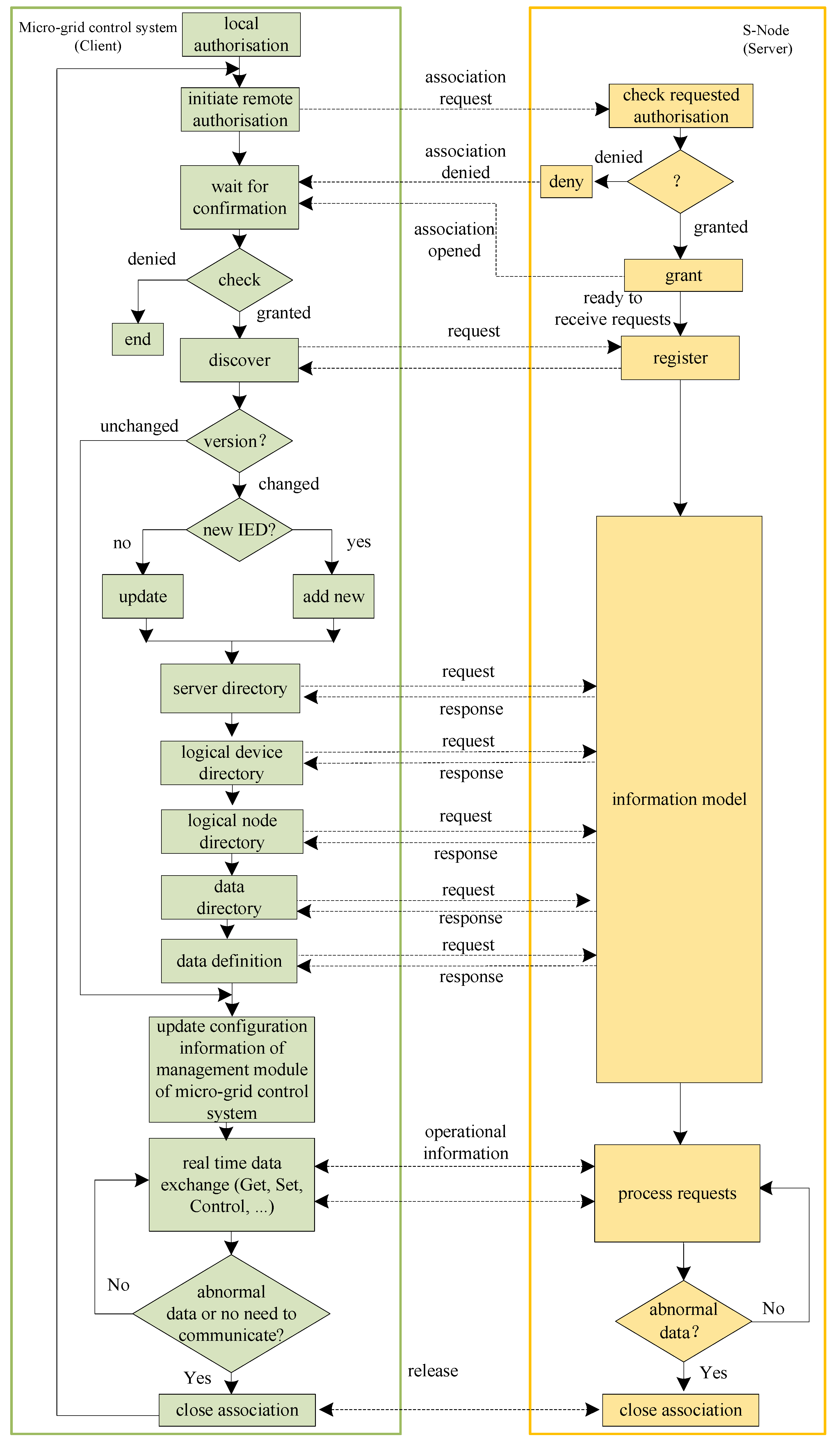
The information model of equipment can be built according to the equipment functions, and then downloaded by the corresponding S-Node. When an S-Node accesses the bay level, it will work as a server, and the micro-grid control system in the station level will work as a client, whose “plug and play” integration procedures are shown in Figure 4.
The procedures of “plug and play” integration mainly include association, authorization, device data dictionary services, and real time data services. The device data dictionary service obtains the used equipment information model which usually could be divided into the server, LD, LN, and data. The real time data services provide the real time data exchange including operation monitoring and control data. These services are shown in Table 1.

Table 1.
Dictionary/real time data services.
| Object | Dictionary Services | Real Time Data Services |
|---|---|---|
| Server | GetServerDirectory | --- |
| LD | GetLogicalDeviceDirectory | --- |
| LN | GetLogicalNodeDirectory | GetAllDataValues |
| Data | GetDataDirectory, GetDataDefination | GetDataValues, SetDataValues |
| Report control block | --- | Report, GetBRCBValues, GetURCBValues |
| Control | --- | Select, SelectWithValue, Cancel, Operate |
Real time data exchange is an important foundation of realizing “plug and play” integration. The main types of data exchange contain the status information (DOs which show either the status of the process or of the function allocated to the LN class, such as the position of a breaker), measured values (DOs measured from the specific process or calculated in the functions such as currents, ECP voltages, and power), controls (DOs which are changed by commands such as DER control mode), settings (DOs which are needed for the function to operate, such as DER power output). The designed functional modules of S-Node and micro-grid control system, and the work procedures for micro-grid data exchange are shown in Figure 5.
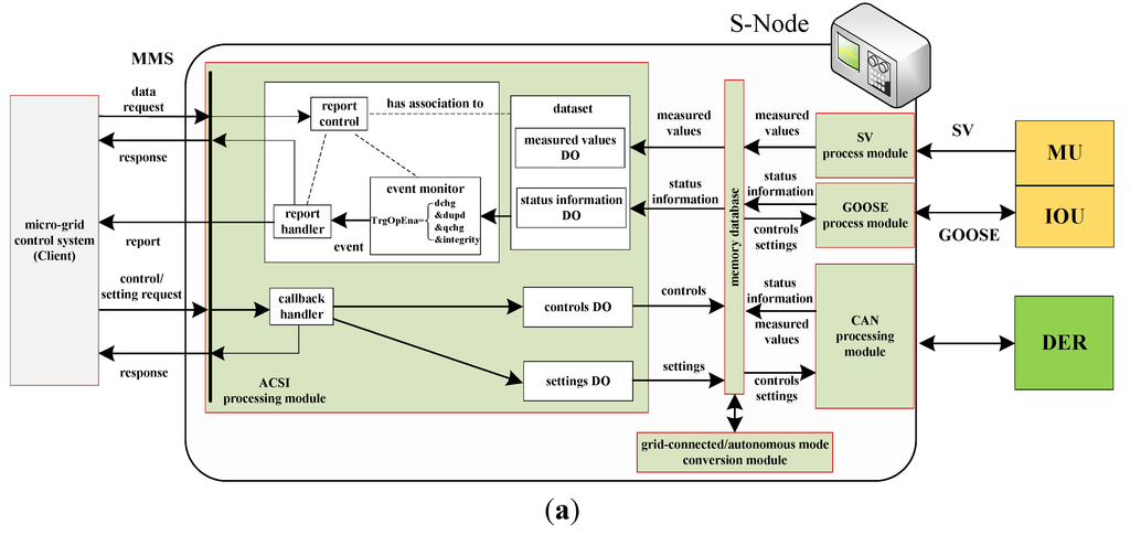

Figure 5.
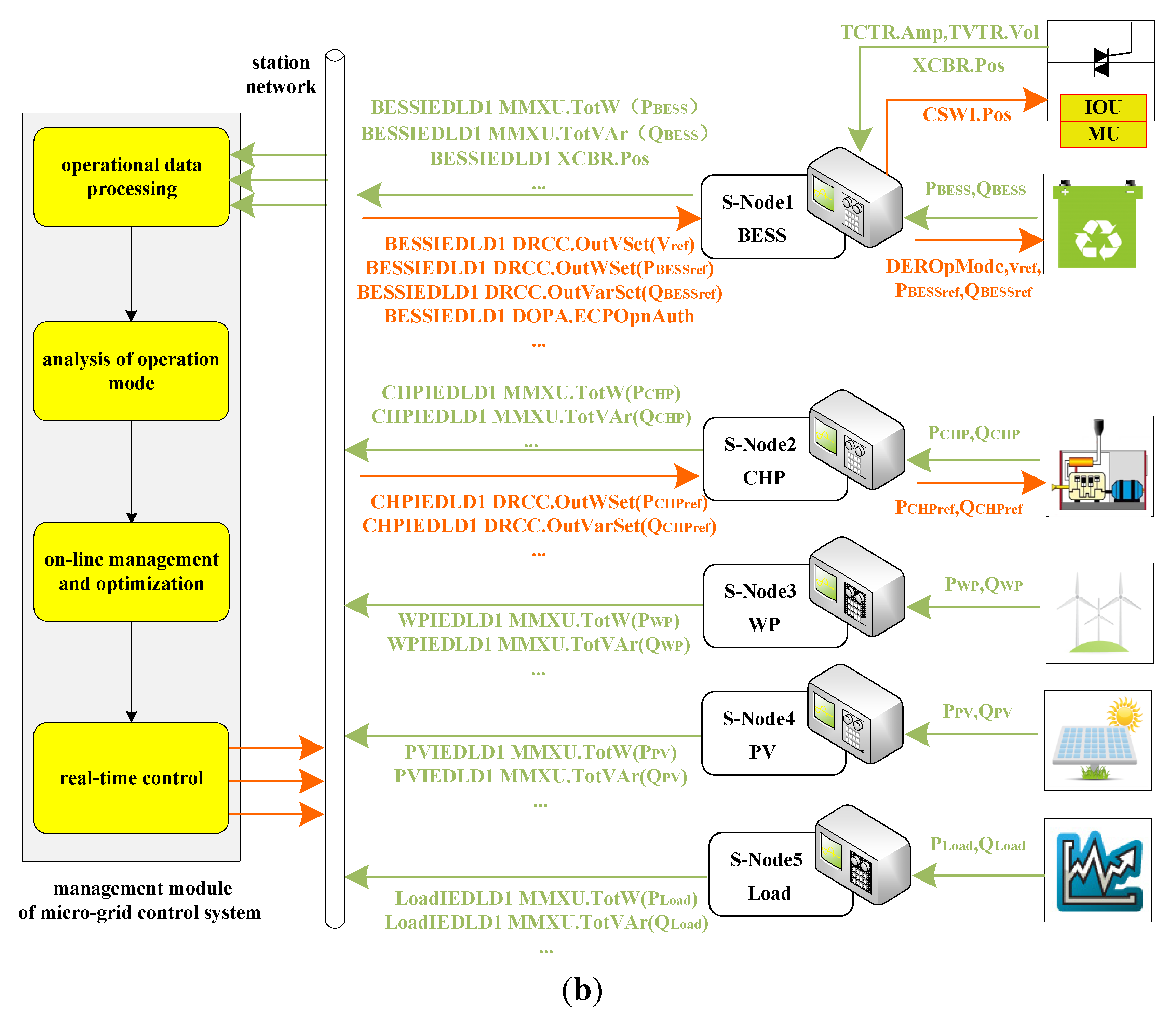
Data exchange in “plug and play” integration: (a) Data exchange for S-Node; (b) Data exchange for micro-grid.
Figure 5.
Data exchange in “plug and play” integration: (a) Data exchange for S-Node; (b) Data exchange for micro-grid.

The work procedures of data exchange for an S-Node are described in Figure 5a. The S-Node gets the measured operation values and status information of the micro-grid equipment through the process bus or CAN bus, and updates the corresponding measured values DOs and status information DOs of the information model, then triggers the report based on the report-control-block options to transmit this information to the micro-grid control system. Meanwhile, the S-Node receives the controls and settings from the micro-grid control system through the station network, and makes the reasonable decisions combined with the grid-connected/autonomous mode conversion module, then further controls the IOU through the process bus or DER through the CAN bus, to manage equipment during the autonomous mode, the grid-connected mode, or operation modes conversion. The typical types of data for real time exchange, which needs to be monitored or utilized when DER “plug and play” integration, are shown in Table 2.
The work procedures of data exchange for a micro-grid are described in Figure 5b. Each S-Node and its loaded information equipment model which can be chosen from Figure 3, will participate in the micro-grid data exchange. Take BESS as an example, and are the active power and reactive power of BESS, respectively, which are modelled by measured values DOs-MMXU.TotW and MMXU.TotVAr, respectively. Breaker position is modelled by the status information DO-XCBR.Pos. Operation mode set is modelled by the settings DO-DOPA.ECPOpnAuth. , , are the voltage reference, active power reference, and reactive power reference of BESS, respectively, which are modelled by controls DOs-DRCC.OutVSet, DRCC.OutWSet, and DRCC.OutVarSet, respectively.
Table 2.
Types of data for real time exchange.
| Data (which be changed and needs to be monitored or utilized) | Data (which be used for characterization of normal or reasonable system operation) | |
|---|---|---|
| Measured values | Total DER/load input and output watt-hours; DER current/active power/reactive power; load current/active power/reactive power; ECP accumulated input/output energy; ECP current/voltage/frequency/active power/reactive power | ECP current ECP voltage ECP frequency ECP active power ECP reactive power |
| Controls | DER operating mode; DER energy schedule; DER start/stop; DER test; DER/load breaker turned on/off | |
| Status information | Type of ECP; ECP connection status; DER controller status; DER start/stop status; voltage high or overcharged; voltage low or undercharged; DER/load breaker status; load demand | |
| Settings | Nominal, min, and max aggregated DER watts/var rating at ECP; nominal, min, and max voltage level/frequency at ECP; DER operational authority at the ECP; DER economic dispatch parameters; ECP energy and ancillary services schedule; set-point for DER power factor/frequency/output voltage; DER output target active/reactive power set-point; DER charge curve; controllable load dispatch schedule | |
When an S-Node starts, it will update the measured values DOs and status information DOs of the information model according to the actual operation data, and send them to the station network. If the micro-grid control system obtains the messages, its management module will perform a series of steps to realize the optimal operation of the micro-grid:
- Step 1:
- Operational data processing, obtains the valid data from IEC 61850 messages.
- Step 2:
- Analysis of operation mode, and determines the current operation mode by the real-time state of XCBR.Pos.
- Step 3:
- On-line management and optimization based on the actual data of DER and load, combined with the related optimization objective and constraints, to generate the controls and settings for optimization operation in the current states, such as and , for BESS using the power control strategies in the grid-connected mode, or for BESS using the voltage source control strategies in the autonomous mode.
- Step 4:
- Real-time control, updates controls DOs and settings DOs for the corresponding S-Node, and send the requests to the station network.
3.2. Grid-Connected/Autonomous Mode Conversion
On the basis of the micro-grid “plug and play” function, a micro-grid needs to provide a reliable power supply for load in the autonomous mode, and participate in energy optimization in the grid-connected mode, and even provide stable and rapid conversion between the two operation modes, which means that the ability to reliably and quickly convert operation modes is becoming an important foundation of micro-grid operation.
In the grid-connected mode, a micro-grid has stable voltage support provided by the utility grid, and the schedulable DERs such as CHP and BESS participate in energy management using the power control strategies. In the autonomous mode, BESS uses the voltage source control strategies to provide stable voltage support for the micro-grid and automatically balance its power fluctuations. When the micro-grid receives the scheduling signal of grid-connected operation, it will close the PCC interconnection switch to transfer to the grid-connected mode, and BESS will transfer to the power control strategies. When the micro-grid receives the scheduling signal of autonomous operation, it will open the PCC interconnection switch to transfer to the autonomous mode, and BESS will transfer to the voltage source control strategies. Therefore, grid-connected/autonomous mode conversion depends on the synergistic regulation of BESS control strategies and the action of the PCC interconnection switch, realized by the grid-connected/autonomous mode conversion module based on IEC 61850 shown in Figure 5(a), which is composed of the fault detection sub-module, the synchronism check sub-module, the BESS state analysis sub-module, and the control decision sub-module. The procedures of grid-connected/autonomous mode conversion are shown in Figure 6:
- (1)
- The fault detection sub-module:TCTR1 and TVTR1 respectively subscribe the PCC current and voltage published by the equipped MU through the process bus. Then the sub-module will detect the utility grid fault and correspondingly output the protection signal represented as ProActSignal (ProActSignal == 1 means that current or voltage faults have been detected, ProActSignal == 0 means no faults).
- (2)
- The synchronism check sub-module: TVTR2 subscribes the micro-grid bus voltage published by equipped MU through the process bus, and provide data for sub-module combing with TVTR1. Then the sub-module will check the synchronization conditions including amplitude and phase, and correspondingly output the synchronization signal represented as RSYN.Rel.stVal (RSYN.Rel.stVal == 1 means that synchronization is ready, RSYN.Rel.stVal == 0 means that synchronization is not ready).
- (3)
- The BESS state analysis sub-module: It output the availability of BESS based on its operation state, represented as ESstatus (ESstatus == 1 means available BESS, ESstatus == 0 means that BESS is not available).
- (4)
- The control decision sub-module: the micro-grid control system transfers scheduling signal to S-Node1, which is represented as DOPA.ECPOpnAuth.setVal (DOPA.ECPOpnAuth.setVal == 1 means micro-grid autonomous operation, DOPA.ECPOpnAuth.setVal == 0 means micro-grid grid-connected operation). Based on the key data including DOPA.ECPOpnAuth.setVal, ProActSignal, RSYN.Rel.stVal, and ESstatus, this sub-module will generate the management orders according to rules as follows:

Figure 6.
Procedures of grid-connected/autonomous mode conversion.
Figure 6.
Procedures of grid-connected/autonomous mode conversion.
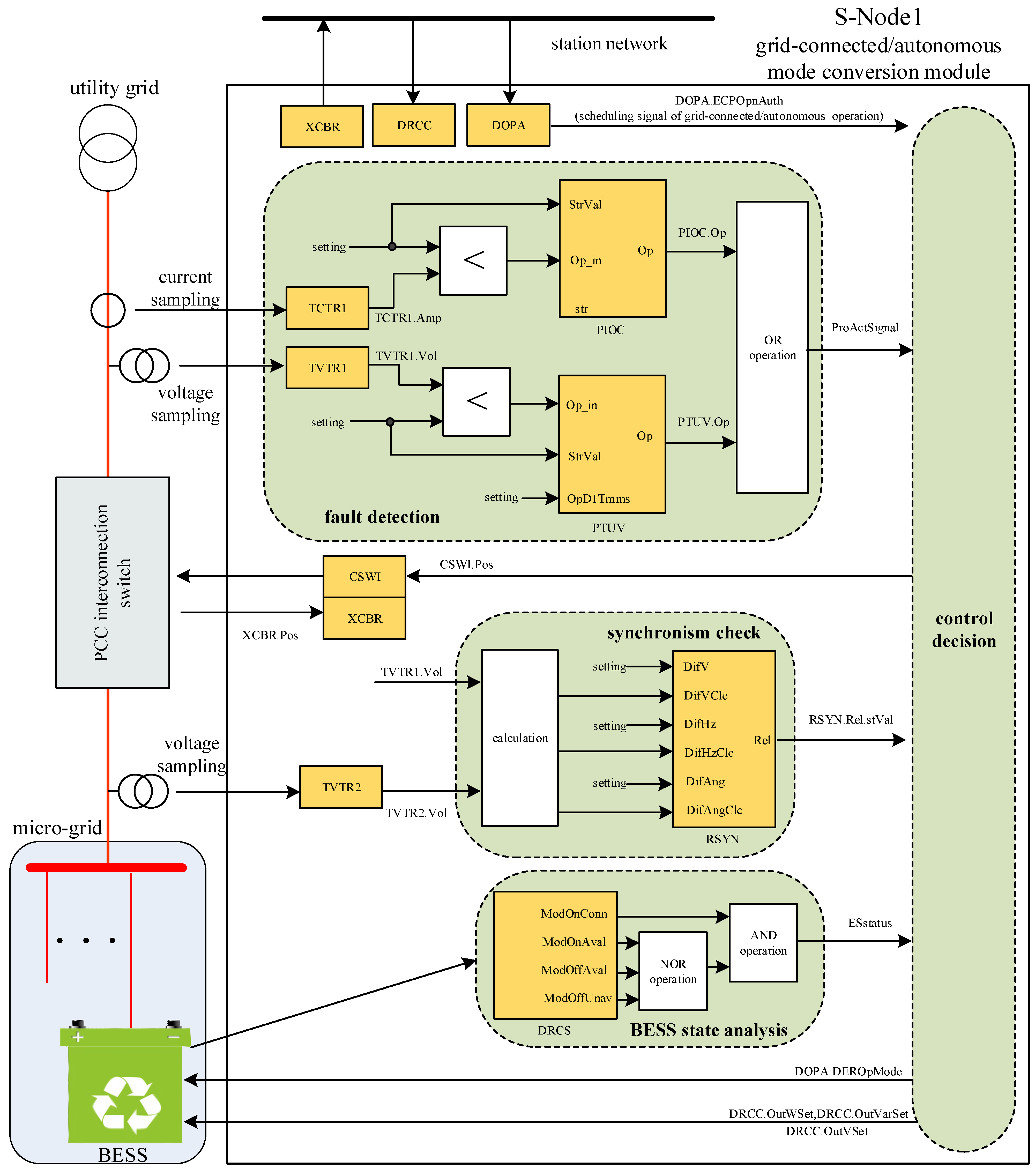
And further, the manage order for IOU equipped in the PCC interconnection switch, represented as controls DO-CSWI.Pos, will be published through the process bus: if CSWI.Pos.Oper.ctlVal is true, S-Node1 chooses the close action for IOU; If CSWI.Pos.Oper.ctlVal is false, S-Node1 chooses the open action for IOU; For other values, S-Node1 does not have any operation. At the same time, the manage order for BESS according to settings DO-DOPA.DEROpMode will be sent through the CAN bus: If DOPA.DEROpMode.eAry[0] == 2, S-Node1 chooses the power control strategies for BESS, then enables and sends , obtained from controls DOs-DRCC.OutWSet and DRCC.OutVarSet, respectively; If DOPA.DEROpMode.eAry[0] == 3, S-Node1 chooses the voltage source control strategies for BESS, then enables and sends obtained from controls DO-DRCC.OutVSet; If DOPA.DEROpMode.eAry[0] == 99, S-Node1 sends the voltage synchronization adjustment order for BESS; For other values, S-Node1 does not have any operation.
When BESS receives the manage orders through the CAN bus, the inverter correspondingly adjusts its control strategies and the corresponding settings. When IOU subscribes the manage orders through the process bus, it correspondingly controls the action of the PCC interconnection switch. Meanwhile, IOU publishes the actual state of the PCC interconnection switch to provide a reliable basis to distinguish the operation modes for the micro-grid control system.
4. Test Results
In order to verify the solution to micro-grid operation using IEC 61850, the micro-grid test platform shown in Figure 1 is built:
- (1)
- Power-system: the nominal voltage is 220 V, the nominal frequency is 50 Hz, and the rated capacity of distribution network transformer is 1 MVA (10 kV/0.4 kV); BESS uses valve-regulated lead acid (VRLA) batteries whose rated capacity is 150 kWh, and the rated capacity of the BESS inverter is 30 kVA, which adopts the voltage source control strategies in the autonomous mode to provide the stable system voltage, or the power control strategies in the grid-connected mode to participate in power dispatching; PV uses a polycrystalline silicon cell array, and the rated capacity of its inverter is 18 kW, which adopts the current source control strategies to realize the maximum power point tracking (MPPT) of solar energy; WP uses the direct-drive permanent-magnet synchronous generator (PMSG), and the rated capacity of the inverter is 4 kW, which adopts the current source control strategies to realize the MPPT of wind energy; CHP uses the Capstone C30 set, and its rated capacity is 30 kVA, and adopts the power control strategies to accept the power dispatching; The peak power of controllable load is 37 kVA.
- (2)
- Information system: MU supports the synchronous sampling of 32-channels, IEEE 1588 time synchronization, and IEC 61850-9-2 messages; IOU supports the GOOSE publish/subscribe pattern, and it can drive the PCC interconnection switch; S-Node has multiple Ethernet ports, and it supports IEC 61850 MMS messages, GOOSE publish/subscribe pattern, and SV publish/subscribe pattern.
4.1. “Plug and Play” Test
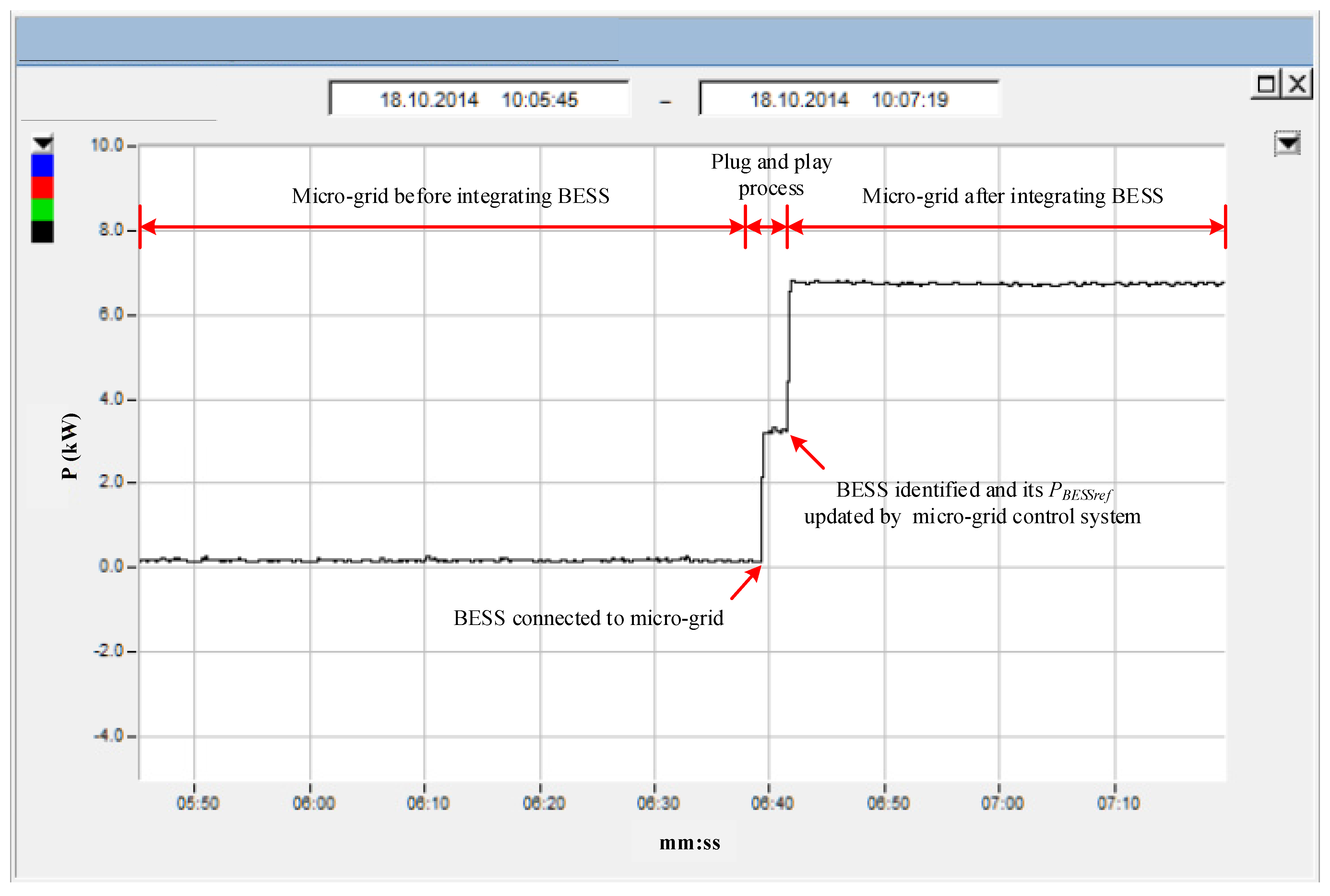
As mentioned in Section 3, DER may be put into operation or shut down frequently during micro-grid operation. Figure 7 shows the power monitoring curves of BESS before and after its connection to the micro-grid test platform. Before 10:06:39 AM, BESS is not connected, and its power out is about 0 kW; from 10:06:39~10:06:42 AM, BESS is connected and its power output is accordance with the default settings ( = 3 kW), meanwhile the “plug and play” process is started as shown in Figure 4: the micro-grid control system obtains BESS information model loaded by S-Node1, then identifies its measured value DO, status information DO, controls DO, and settings DO to update the micro-grid configuration information, and further generates the optimized through its on-line management and optimization module; After 10:06:42, the “plug and play” process is finished, BESS operates under = 7 kW which is updated by the micro-grid control system. As shown in Figure 7, the micro-grid can rapidly realize the “plug and play” function, and improve the efficiency of system integration and operation management.
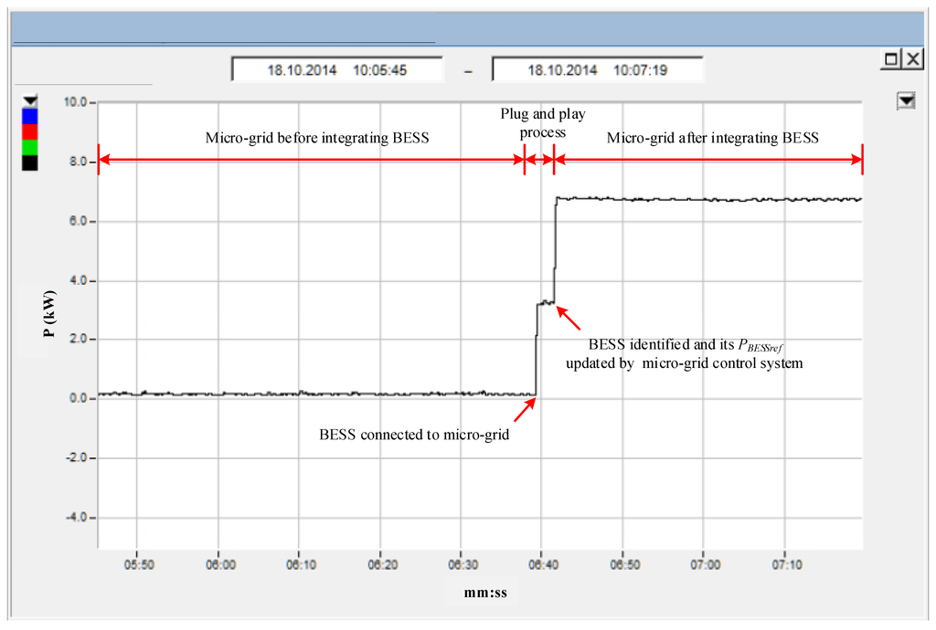
Figure 7.
Power monitoring curves of BESS.
Figure 7.
Power monitoring curves of BESS.
4.2. Grid-Connected/Autonomous Mode Conversion Test
Figure 8 shows the experimental results when the micro-grid control system converts the gird-connected mode to the autonomous mode (channel 1 records the A-phase voltage of micro-grid’s ac bus, channel 2 records the A-phase voltage of PCC, channel 3 records A-phase current of PCC, channel 4 records A-phase current of BESS). As mentioned in Section 3, S-Node1 sets ESstatus = 1 during micro-grid normal operation, and obtains DOPA.ECPOpnAuth.setVal == 1 when it receives the mode conversion orders, and then sets DOPA.DEROpMode.eAry[0] == 3 and CSWI.Pos.Oper.ctlVal is false based on the control decision sub-module from Equation (1). Further, S-Node1 publishes the open action for IOU through the process bus, and sends the voltage source control strategies and to BESS through the CAN bus ( is obtained from the controls DO-DRCC.OutVSet of BESS information model with default values 220 V, which is updated by micro-grid control system as shown in Figure 5).
As shown in Figure 8, S-Node1 has accurately analyzed the settings DO-DOPA updated by the micro-grid control system, and obtained the specific orders, and then generated the corresponding command orders: CSWI.Pos.Oper.ctlVal is false that is quickly published, and then the PCC interconnection switch is quickly opened, so the current of channel 3 declines to zero in 10 ms; At the same time, according to that DOPA.DEROpMode.eAry[0] == 3, the voltage source control strategies and obtained from the controls DO-DRCC.OutVSet are sent to BESS to dynamically adjust the output voltage of the inverter, the voltage amplitude of channel 1 is continuous before and after the mode conversion, which ensures the uninterrupted supply of power for the micro-grid.
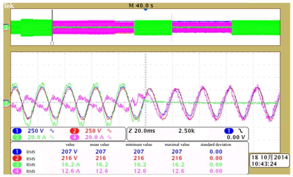
Figure 8.
Conversion of the grid-connected mode to the autonomous mode.
Figure 8.
Conversion of the grid-connected mode to the autonomous mode.

Figure 9 shows the experimental results when the micro-grid control system converts from the autonomous mode to the gird-connected mode. As mentioned in Section 3, S-Node1 sets ESstatus = 1 during micro-grid normal operation, and obtains DOPA.ECPOpnAuth.setVal == 0 when it receives the mode conversion orders, and then checks the synchronization states: if the voltage synchronization between the micro-grid ac bus and utility grid is not ready, S-Node1 will set RSYN.Rel.stVal = 0, and further obtain DOPA.DEROpMode.eAry[0] == 99; If the synchronization is ready, S-Node1 will set RSYN.Rel.stVal = 1, and further determine DOPA.DEROpMode.eAry[0] == 2 and CSWI.Pos.Oper.ctlVal is true based on Equation (1). Further, S-Node1 publishes the close action for IOU through the process bus, and sends the power control strategies and , to BESS through the CAN bus ( and are respectively obtained from the controls DOs- DRCC.OutWSet and DRCC.OutVarSet of BESS information model, and the default == −5 kW and == 0 kvar are updated by micro-grid control system as shown in Figure 5).
As shown in Figure 9, S-Node1 has accurately analyzed the specific orders from the settings DO-DOPA updated by the micro-grid control system, and generated the corresponding command orders combined with the current operation state: according to that DOPA.DEROpMode.eAry[0] == 99, BESS continuously adjusts its output voltage. When the voltages of channel 1 and channel 2 meet the synchronization requirements, CSWI.Pos.Oper.ctlVal is true, which is quickly published, and then the PCC interconnection switch is closed, the micro-grid is converted to the grid-connected mode. The voltage amplitude of channel 1 is continuous before and after the mode conversion, which ensures the normal power supply and reliable DER operation; At the same time, according to DOPA.DEROpMode.eAry[0] == 2, the power control strategies and , which are respectively obtained from the controls DO-DRCC.OutWSet and DRCC.OutVarSet are sent to BESS to dynamically adjust the output power of the inverter, and the current of channel 4 is regulated to the new steady state in two cycles, which converts the state of power output in the autonomous mode to the state of power storage.
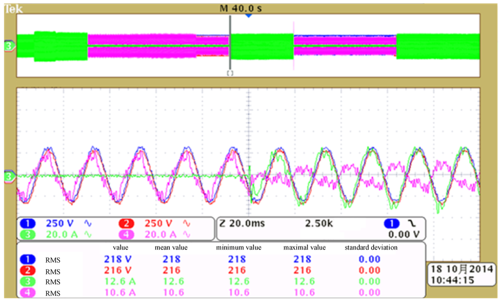
Figure 9.
Conversion of the autonomous mode to the grid-connected mode.
Figure 9.
Conversion of the autonomous mode to the grid-connected mode.

The experimental results show that S-Node 1 accurately analyzes the specific orders from the settings DO and controls DO updated by the micro-grid control system, and responds fast to generate the command orders for the corresponding micro-grid equipment. The voltage amplitude of the micro-grid’s ac bus is continuous before and after the mode conversion including converting the grid-connected mode to the autonomous mode and vice versa, which ensures the system reliability of the micro-grid.
Meanwhile, the voltage amplitude of PCC is also continuous before and after micro-grid mode conversion. This result shows that the utility grid has not been affected by the micro-grid regardless of its operation conditions, and ensures the overall system reliability all the time.
5. Conclusions
Establishment of standardized, real-time, and safe information systems, and providing micro-grid “plug and play” functions can significantly improve the efficiency of micro-grid system integration and operation management. IEC 61850 has a standardized system language, communication services and structure, therefore, this paper presents a solution for micro-grid operation based on IEC 61850, proposes the design of micro-grid “plug and play” functions, their operation mode conversion, and their specific implementation methods. The tests verified by using the developed IED and micro-grid test platform show that IEC 61850 provides a rapid information modeling technology and standardized data exchange network for micro-grid operation, and the solutions can automatically identify the device characteristics and adjust their operation strategies to adapt to new system states, and achieve a reliable system operation mode conversion. Based on the obtained results, this research can contribute to the complex operation management of micro-grids.
Acknowledgments
This research was supported by the National Natural Science Foundation of China (Grant Nos. 51407177) and the National Key Basic Research Program of China (Grant Nos. 2012CB215204).
Author Contributions
The authors contributed equally in preparing this manuscript.
Acronyms
| DER | Distributed energy resources |
| CHP | Combined heat and power |
| WP | Wind power |
| PV | Photovoltaic system |
| SCADA | Supervisory control and data acquisition system |
| EMS | Energy management system |
| ACSI | Abstract communication service interfaces |
| CDC | Common data classes |
| LN | Logical node |
| EV | Electric vehicles |
| IED | Intelligent electronic devices |
| WAN | Wide area network |
| CAN | Controller area network |
| IOU | Input/output unit |
| MU | Merging unit |
| DG | Distributed generation |
| BESS | Battery energy storage system |
| PCC | Point of common connection |
| ECP | Electrical connection point |
| SCL | Substation configuration language |
| MMS | Manufacturing message specification |
| GOOSE | Generic object oriented substation event |
| SV | Sampled values |
| DO | Data objects |
| XCBR | Circuit breakers |
| CSWI | Switch controller |
| DCRP | DER plant corporate characteristics at the ECP |
| DOPA | DER operational authority at the ECP |
| DOPR | Operational characteristics at ECP |
| DOPM | Operating mode at ECP |
| DPST | Status information at the ECP |
| DCCT | DER economic dispatch parameters |
| DSCC | DER energy and/or ancillary services schedule control |
| DSCH | DER energy and/or ancillary services schedule |
| MMTR | Metering |
| DPVC | Photovoltaics array controller |
| DTRC | Tracking controller |
| DPVM | Photovoltaic module characteristics |
| DPVA | Photovoltaics array characteristics |
| XSWI | Switch |
| ZINV | Inverter |
| ZRCT | Rectifier |
| MMDC | Measurement of intermediate DC |
| DRCT | DER controller characteristics |
| DRCS | DER controller status |
| DRCC | DER supervisory control |
| FSEQ | Sequencer |
| MMXU | Electrical measurements |
| STMP | Temperature measurements |
| MHET | Heat measured values |
| MMET | Meteorological conditions |
| ZBAT | Battery systems |
| ZBTC | Battery charger |
| WCNV | Wind turbine converter information |
| WGEN | Wind turbine generator information |
| WTRM | Wind turbine transmission information |
| WROT | Wind turbine rotor information |
| WTUR | Wind turbine general information |
| WSLG | Wind turbine state log information |
| WREP | Wind turbine report information |
| WALM | Wind power plant alarm information |
| WAPC | Wind power plant active power controller |
| WRPC | Wind power plant reactive power controller |
| WNAC | Wind turbine nacelle information |
| WYAW | Wind turbine yawing information |
| WTOW | Wind turbine tower information |
| WMET | Wind turbine melerological information |
| RSYN | Synchronization |
| DGEN | DER unit generator |
| DRAT | DER generator ratings |
| DRAZ | DER advanced generator ratings |
| DCST | Generator cost |
| DREX | Excitation ratings |
| DEXC | Excitation operations |
| DCTS | CHP thermal storage |
| DCHB | CHP Boiler System |
| DCHC | CHP system controller |
| MFUL | Fuel characteristics |
| DFLV | Fuel delivery system |
| SVBR | Vibration conditions |
| MPRS | Pressure measurements |
| MENV | Emissions measurements |
| MFLW | Flow measurements |
| PIOC | Instantaneous over current |
| PTOC | Time over current |
| PTUV | Time under voltage |
| PTOV | Time over voltage |
| TCTR | Current transformer |
| TVTR | Voltage transformer |
| LD | Logical device |
| VRLA | Valve-regulated lead acid |
| MPPT | Maximum power point tracking |
| PMSG | Permanent-magnet synchronous generator |
Conflicts of Interest
The authors declare no conflict of interest.
References
- Eghtedarpour, N.; Farjah, E. Power control and management in a hybrid AC/DC microgrid. IEEE Trans. Smart Grid 2014, 5, 1494–1505. [Google Scholar] [CrossRef]
- Zamani, M.A.; Sidhu, T.S.; Yazdani, A. Investigations into the control and protection of an existing distribution network to operate as a microgrid: A case study. IEEE Trans. Ind. Electron. 2014, 61, 1904–1915. [Google Scholar] [CrossRef]
- Alegria, E.; Brown, T.; Minear, E.; Lasseter, R.H. CERTS microgrid demonstration with large-scale energy storage and renewable generation. IEEE Trans. Smart Grid 2014, 5, 937–943. [Google Scholar] [CrossRef]
- Duong, T.; Khambadkone, A.M. Energy management for lifetime extension of energy storage system in micro-grid applications. IEEE Trans. Smart Grid 2013, 4, 1289–1296. [Google Scholar] [CrossRef]
- Deng, W.; Pei, W.; Qi, Z.P. Micro-grid information exchange based on IEC 61850. Proc. Autom. Electr. Power Syst. 2013, 37, 6–11. (In Chinese) [Google Scholar]
- Ren, Y.M.; Cao, F.M. New development and new application of IEC 61850. Proc. Autom. Electr. Power Syst. 2013, 37, 1–6. (In Chinese) [Google Scholar]
- Ustun, T.S.; Ozansoy, C.R.; Zayegh, A. Modeling of a centralized microgrid protection system and distributed energy resources according to IEC 61850-7-420. IEEE Trans. Power Syst. 2012, 27, 1560–1567. [Google Scholar] [CrossRef]
- Timbus, A.; Larsson, M.; Yuen, C. Active management of distributed energy resources using standardized communications and modern information technologies. IEEE Trans. Ind. Electron. 2009, 56, 4029–4037. [Google Scholar] [CrossRef]
- Colet-Subirachs, A.; Ruiz-Alvarez, A.; Gomis-Bellmunt, O.; Alvarez-Cuevas-Figuerola, F.; Sudria-Andreu, A. Centralized and distributed active and reactive power control of a utility connected microgrid using IEC61850. IEEE Syst. J. 2012, 6, 58–67. [Google Scholar] [CrossRef]
- Yoo, B.K.; Yang, S.H.; Yang, H.S.; Kim, W.Y.; Jeong, Y.S.; Han, B.M.; Jang, K.S. Communication architecture of the IEC 61850-based micro grid system. J. Electr. Eng. Technol. 2011, 6, 605–612. [Google Scholar] [CrossRef]
- Stjepan, S.; Tomislav, D.; Tomislav, C.; Marko, D. Economic dispatch of virtual power plants in an event-driven service-oriented framework using standards-based communications. Electr. Power Syst. Res. 2011, 81, 2108–2119. [Google Scholar] [CrossRef]
- Petersen, B.; Winther, D.; Pedersen, A.; Poulsen, B.; Traeholt, C. Integrating intelligent electric devices into distributed energy resources in a cloud-based environment. In Proceedings of the 4th IEEE/PES Innovative Smart Grid Technologies Europe (ISGT EUROPE), Lyngby, Denmark, 6–9 October 2013; Volume 1, pp. 1–5.
- Schmutzler, J.; Groning, S.; Wietfeld, C. Management of distributed energy resources in IEC 61850 using Web services on devices. In Proceedings of the 2011 IEEE International Conference on Smart Grid Communications (SmartGridComm), Brussels, Belgium, 17–20 October 2011; Volume 1, pp. 315–320.
- Stjepan, S.; Juraj, G.; Tomislav, D. A device-level service-oriented middleware platform for self-manageable DC microgrid applications utilizing semantic-enabled distributed energy resources. Electr. Power Energy Syst. 2014, 54, 576–588. [Google Scholar] [CrossRef]
- Communication Networks and Systems for Power Utility Automation—Part 7–420: Basic Communication Structure–Distributed Energy Resources Logical Nodes; IEC Std. 61850 Ed 1.0; International Electrotechnical Commission (IEC): Geneva, Switzerland, 2009.
- Communication Networks and Systems for Power Utility Automation—Part 7–1: Basic Communication Structure—Principles and Models; IEC Std. 61850 Ed 2.0; International Electrotechnical Commission (IEC): Geneva, Switzerland, 2011.
- Communication Networks and Systems for Power Utility Automation—Part 7–2: Basic Information and Communication Structure—Abstract Communication Service Interface (ACSI); IEC Std. 61850 Ed 2.0; International Electrotechnical Commission (IEC): Geneva, Switzerland, 2010.
- Communication Networks and Systems for Power Utility Automation—Part 7–3: Basic Communication Structure-Common Data Classes; IEC Std. 61850 Ed 2.0; International Electrotechnical Commission (IEC): Geneva, Switzerland, 2010.
- Communication Networks and Systems for Power Utility Automation—Part 7–4: Basic Communication Structure—Compatible Logical Node Classes and Data Object Classes; IEC Std. 61850 Ed 2.0; International Electrotechnical Commission (IEC): Geneva, Switzerland, 2010.
© 2015 by the authors; licensee MDPI, Basel, Switzerland. This article is an open access article distributed under the terms and conditions of the Creative Commons Attribution license (http://creativecommons.org/licenses/by/4.0/).