Abstract
This paper presents an indirect matrix converter (IMC) topology for hybrid electric vehicle (HEV) application with three-phase and single-phase outputs. The HEV includes mechanical, electrical, control, and electrochemical systems among others. In the mechanical system, a traction motor and a compressor motor are used to drive the HEV. The traction motor and the compressor motor are usually operated as three-phase and single-phase motors, respectively. In this respect, a dual AC-drive system can operate the traction and the compressor motor simultaneously. Furthermore, compared to a conventional dual matrix converter system, the proposed topology can reduce the number of switches that the dual outputs share with a DC-link. The application of this system for HEV has advantages, like long lifetime and reduced volume due to the lack of a DC-link. The proposed control strategy and modulation schemes ensure the sinusoidal input and output waveforms and bidirectional power transmission. The proposed system for the HEV application is verified by simulation and experiments.
1. Introduction
In recent years, the problems regarding environmental pollution have become a significant issue. In response, researchers have made an effort to study green technologies for environmental conservation. Green technologies can help mitigate global warming and conserve energy resources. In this regard, interests and demands have increased for electric vehicles (EVs) and hybrid electric vehicles (HEVs) associated with green technologies [1]. EV and HEV comprise a multidisciplinary research field and have a complex structure because of the integration of mechanical, electrical, control, magnetic, and electrochemical systems. In the mechanical system, a traction motor and a compressor motor are used to drive the EV and HEV [2].
Some industrial systems require several variable-speed drives in a dual-drive configuration. In this regard, two three-phase voltage source inverters with a common DC-link are generally used for the dual-drive configuration; therefore, 12 additional switching devices are necessary. Dual AC-drive systems have been studied for special industrial applications such as electric vehicles, steel processing, and railway traction systems. However, the limitations of general dual AC-drive systems are that they require DC-link components or perhaps a phase shifting transformer. Moreover, the systems require additional switching devices. Among the DC-link components, the capacitor is bulky and has a short lifetime compared to other power electronics components. As a result, general dual AC-drive systems with two inverters and DC-link elements have disadvantages including as low efficiency, high volume and short lifetime [3,4,5,6,7].
AC/AC power conversion systems are widely used in traditional industry applications such as adjustable-speed motor drives, renewable energy conversion systems, and transmission uninterruptible power supplies [8,9,10]. One of the AC/AC power conversion systems, the indirect matrix converter (IMC), is structurally distinct from the direct matrix converter (DMC). However, the specifications of the IMC are very similar to the DMC [11]. The IMC consists of 18-bidirectional switches and includes a rectifier stage and an inverter stage that is connected to a fictitious DC-link, which does not include DC-link energy storage elements. Therefore, this structure of the IMC, similar to that of a back-to-back converter, eliminates the DC-link energy storage elements [12]. The main advantage of the IMC is the absence of bulky and short-lifetime DC-link energy storage elements such as capacitors. As a result, the IMC has reduced weight and volume. Furthermore, the IMC can have a simplified structure by decreasing the number of switches in the rectifier stage without a decline in performance. The resulting converters are designated as sparse matrix converters (SMCs) or very sparse matrix converters (VSMCs), which are composed of only 15 or 12 switches for bidirectional transfer of power in their simple form [13,14,15].
Using an IMC topology for the dual-drive configuration decreases the disadvantages of the general dual AC-drive systems with two inverters and DC-link elements. The IMC topology with dual outputs is composed of an input stage and two output stages with a pair of conventional three-leg inverters without DC-link energy storage elements [16,17,18]. Recently, in order to reduce the total cost and to save the space, a five-leg inverter has been used as a dual output inverters [19,20].
This paper presents a development of system for the HEV application with three-phase and single-phase outputs using the IMC. IMC without any DC-link capacitor, which is used for power conversion system for the HEV application, is able to control the three-phase traction motor and the single-phase compressor motor simultaneously. This power conversion system guarantees the long lifetime due to absence of the DC-link energy storage elements. Furthermore, through the parallel operation of the three-phase and single-phase outputs, the system for the HEV application has decreased its volume. Additionally, this paper presents an application oriented AC dual output based VSMC where the number of switches is also reduced in comparison with the traditional dual drive systems.
This paper is organized as follows: Section 2 presents the HEV application. Specifically, the HEV structure is presented, consisting of the traction motor and the compressor motor. Section 3 presents the topology of the dual-output drive system. In addition, the operational principles and the modulation strategies for the topology are introduced in Section 3. Simulation studies and experimental results for the three-phase and single-phase inductive loads are discussed in Section 4 and Section 5, respectively. The simulation and experimental results are provided to demonstrate that AC dual outputs are fed independently from the three-phase voltage source and to confirm the feasibility of the proposed methods. Finally, Section 6 discusses the conclusions of this paper.
2. The Hybrid Electric Vehicle Application
2.1. Structure of the Hybrid Electric Vehicle
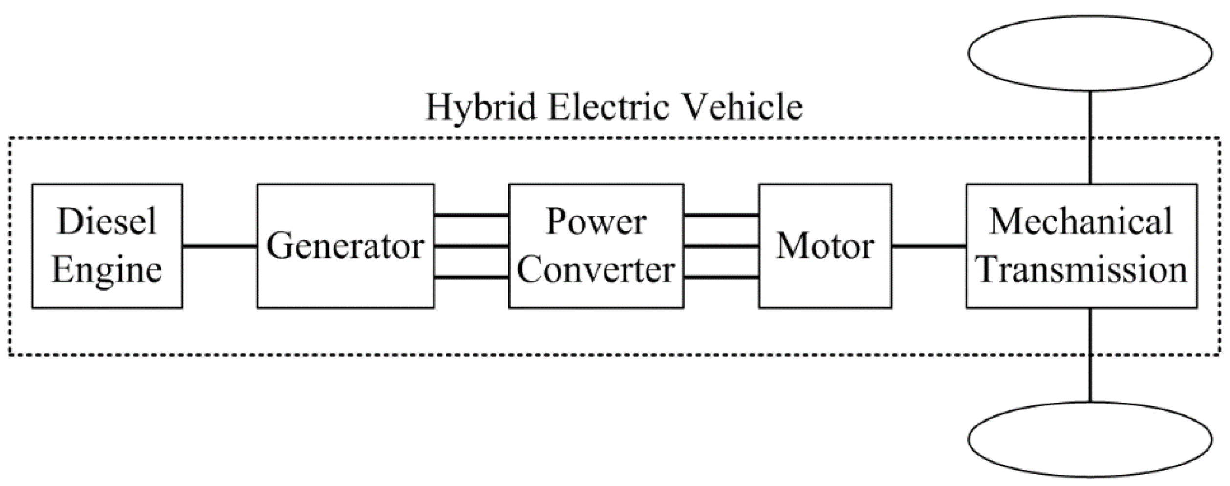
The HEV has a complex structure because of the integration of various systems. The structure of the HEV is classified into five parts according to the function. They are the diesel engine, generator, power converter, motor and mechanical transmission, as shown in Figure 1. The generator of the HEV produces three-phase AC voltage from the diesel engine. The three-phase AC voltage is then converted for the operation of the motor through the power converter. In particular, the motor parts are very important components for driving the HEV system. The motor parts include traction and compressor motors, which are usually used as a three-phase motor and single-phase motor, respectively [21].

Figure 1.
Structure of the hybrid electric vehicle classified into five basic parts.
Figure 1.
Structure of the hybrid electric vehicle classified into five basic parts.
2.2. Traction Motor and Compressor Motor
The traction motor in the motor parts has a significant role in the overall performance because of its contribution to the electric propulsion system. Because the HEV system is also driven through the propulsion system, the traction motor is the heart of the HEV system. In recent times, research has been carried out to actively control the traction motor. Fundamentally, a method using a current source inverter is presented in [22] and a method based on the matrix converter (MC) is presented in [23]. Apart from these methods, various other methods for the drive and control of the traction motor have been studied.
The other component of the motor parts is the compressor motor. The main functions of the compressor in the HEV system are heating, ventilation, and air-conditioning [24]. Generally, the engine belt-driven compressor motor is used for these functions. However, the electrically driven compressor has the advantages of being adjusted irrespective of the engine speed and less leakage of refrigerant into atmosphere because of the elimination of the rotating seals.
2.3. Integrated Traction and Compressor Drive System
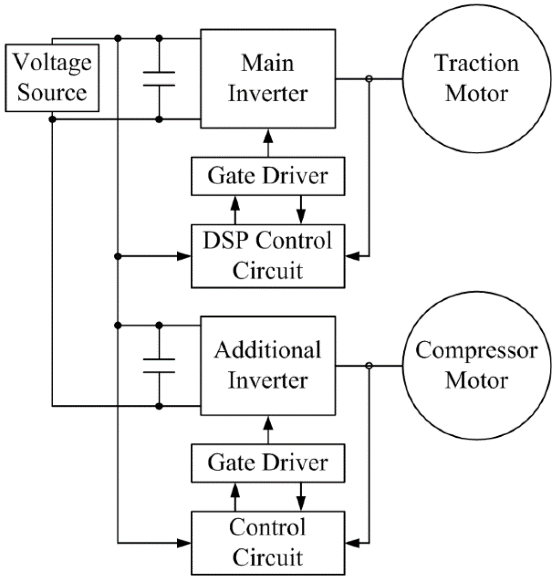
In order to operate the traction motor and compressor motor simultaneously, an integrated traction and compressor drive system is studied. Figure 2 shows a conventional traction and compressor motor drive system using two separate inverters [25]. Through a further study, when the traction motor is a three-phase motor and the compressor motor is a two-phase motor, a five-legged inverter is used to control the integrated traction and compressor drive system. The system proposed in [26] reduces the compressor drive cost by an additional inverter. However, the integrated system has the disadvantages of having short lifetime and large volume because it includes a capacitor. Moreover, the system has more switches for the additional inverter stage. In order to eliminate these disadvantages, the IMC topology with three-phase and single-phase outputs is presented in this paper for the HEV application.

Figure 2.
Conventional traction and compressor motor drive system using two separate inverters.
Figure 2.
Conventional traction and compressor motor drive system using two separate inverters.
3. Topology and Modulation Strategies of the Dual Output Drive System for Hybrid Electric Vehicle Application
3.1. Indirect Matrix Converter Topology
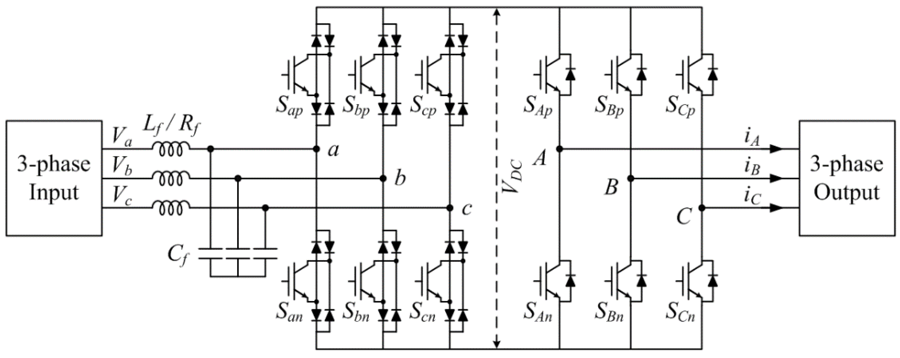
In general, the IMC is a two-stage AC/AC power converter and is composed of a current source rectifier on the input side and a voltage source inverter on the output side. Because it does not have a DC-link energy storage element, the rectifier stage and the inverter stage are directly connected through the fictitious DC-link. Additionally, according to several studies, the number of switches in the current source rectifier stage in the IMC is reduced. This new topology of the IMC with the reduced number of switches is called the SMC. Moreover, the VSMC eliminates more switches in the rectifier stage compared to the SMC. The SMC and the VSMC are functionally equivalent to the IMC; however, they are characterized by a lower realization effort and a lower control complexity. A circuit configuration of the VSMC is shown in Figure 3. The VSMC is composed of 12 IGBTs and 30 diodes.

Figure 3.
Topology of the very sparse matrix converter.
Figure 3.
Topology of the very sparse matrix converter.
3.2. Proposed Dual Output Drive System Topology for the Hybrid Electric Vehicle Application
This paper presents a dual output drive system based on the VSMC. The proposed topology consists of a current source rectifier connected to a four-legged inverter stage via a fictitious DC-link without any storage elements. In this topology, the current source rectifier stage located in the input stage is shared by two loads, including a three-phase load and a single-phase load.
Figure 4 shows the proposed dual-output drive system topology, with a VSMC with 14 switches. The rectifier stage has six switches each having four diodes and is arranged as a front-end current source rectifier. The other eight switches in the inverter stage have antiparallel diodes for forming a rear-end voltage source inverter. Furthermore, in this topology, a three-phase grid and an inductor-capacitor filter are located in the input stage. Last, the dual outputs are located in the output stage, supplying the three-phase load and the single-phase load.

Figure 4.
Proposed dual output drive system based on VSMC for hybrid electric vehicle application.
Figure 4.
Proposed dual output drive system based on VSMC for hybrid electric vehicle application.
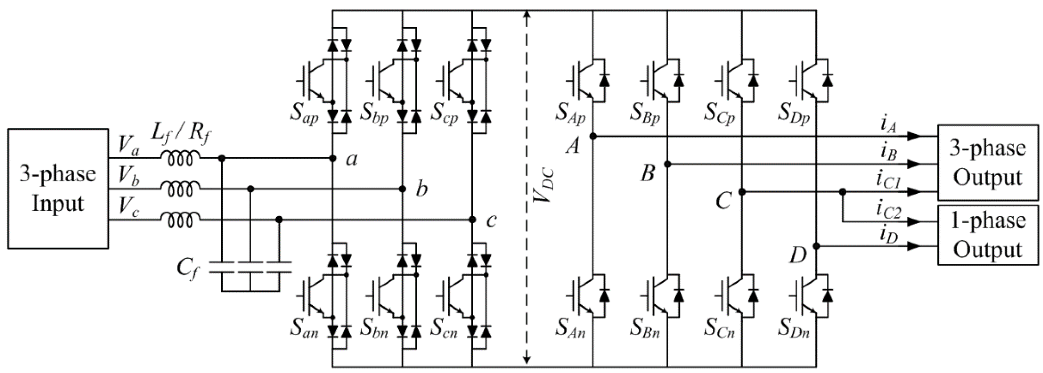
In this topology, a four-legged inverter is used as a power converter, that’s why two loads have to share the common leg C. According to this strategy, the proposed topology can reduce two power switches in the inverter stage compared to the conventional dual output IMC topology on the basis of the parallel connection of the legs.
3.3. Modulation Strategy of the Rectifier Stage
In this topology, the modulation strategy of the rectifier stage is as same as the conventional modulation methods of the rectifier stage in the IMC. The purpose of the modulation in the rectifier stage is to produce maximum voltage in the DC-link. Furthermore, modulation is required for the maintenance of the sinusoidal input current and the unity input power factor. The rectifier stage synthesizes a positive voltage of the DC-link by selecting a switching state. It is usually operated with the upper and lower switches being ON at all instants. The corresponding active duty cycles (dx, dy) for the rectifier stage can be determined by the input phase currents and the corresponding input voltages, which are expressed as.
where mi is the modulation index of the rectifier stage and θi is the phase angle of the input current. These duty cycles directly drive the rectifier stage.
Additionally, the fictitious DC-link voltage (VDC) is time-varying with its normalized local average value over a fundamental period, which is calculated by
where Vi is the amplitude of the input phase voltage and φ is an angle between the input voltage and the input current, that is, the input power factor angle.
3.4. Modulation Strategy of the Four-Leg Inverter Stage
A conventional space vector pulse width modulation (PWM) method using offset voltage Voff is used to drive the four-leg inverter stage in order to control the three-phase load and the single-phase load. Assuming that the three-phase references are represented by VA(1)*, VB(1)*, and VC(1)*, and the single-phase references are represented by VC(2)* and VD(2)*, the modulation references VA(1), VB(1), VC(1), VC(2), and VD(2) of the space vector PWM are calculated as in Equations (3) and (4). In these modulation references, the number 1 in the parentheses means load 1 (three-phase load), and the number 2 in parentheses means load 2 (single-phase load). Using the equations of the modulation references, the inverter stage in the proposed dual output drive system is modulated.
where Voff = −0.5max(VA(1)*, VB(1)*, VC(1)*) + 0.5min(VA(1)*, VB(1)*, VC(1)*).
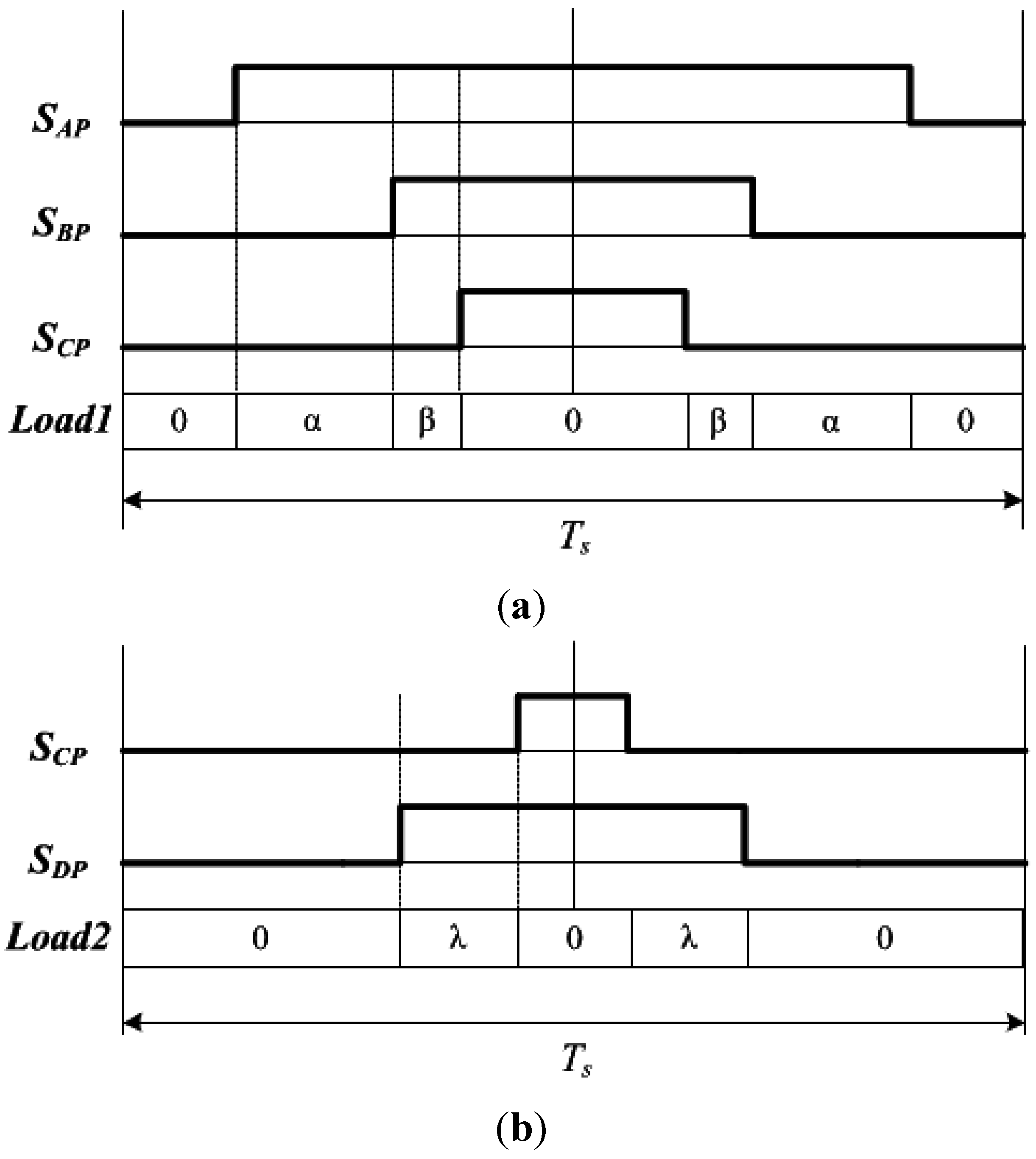
Figure 5 shows the switching state of the inverter stage considering only the three-phase and single-phase loads. However, because the three-phase and single-phase loads share the common leg C, as in the output stage of Figure 4, the duty cycle of the switches of phase C influences the two loads simultaneously. Therefore, in order to synchronize the modulation references VC(1) and VC(2), they must be adjusted. These modulation references can be implemented by changing the zero vectors of the two loads, while maintaining the active vectors as they are. According to this method, the on-time of the switches in one sampling period is determined as
This strategy means combining the zero vectors in the three-phase and single-phase loads because they share the common leg C. That is, the switching on-time of the zero vector considering only the single-phase load as in Figure 5b is added to the switching on-time of the zero vector considering only the three-phase load as in Figure 5a. From another viewpoint, the switching on-time of the zero vector as in Figure 5a is added to the switching on-time as in Figure 5b.

Figure 5.
Switching state of the inverter stage: (a) considering only the three-phase load; (b) considering only the single-phase load.
Figure 5.
Switching state of the inverter stage: (a) considering only the three-phase load; (b) considering only the single-phase load.
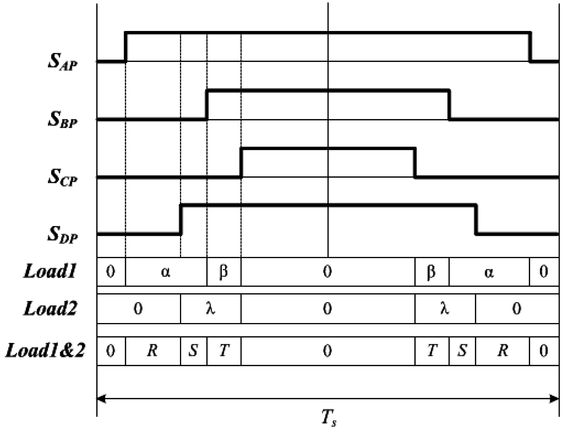
Thus, Figure 6 shows the switching state of the inverter stage considering the dual outputs, both the three-phase load and single-phase load. Furthermore, the inverter stage employs a double-sided switching sequence, but with asymmetrical halves because each half should be applied to a rectifier stage switching sequence.

Figure 6.
Switching state of the inverter stage considering the three-phase output and single-phase output.
Figure 6.
Switching state of the inverter stage considering the three-phase output and single-phase output.
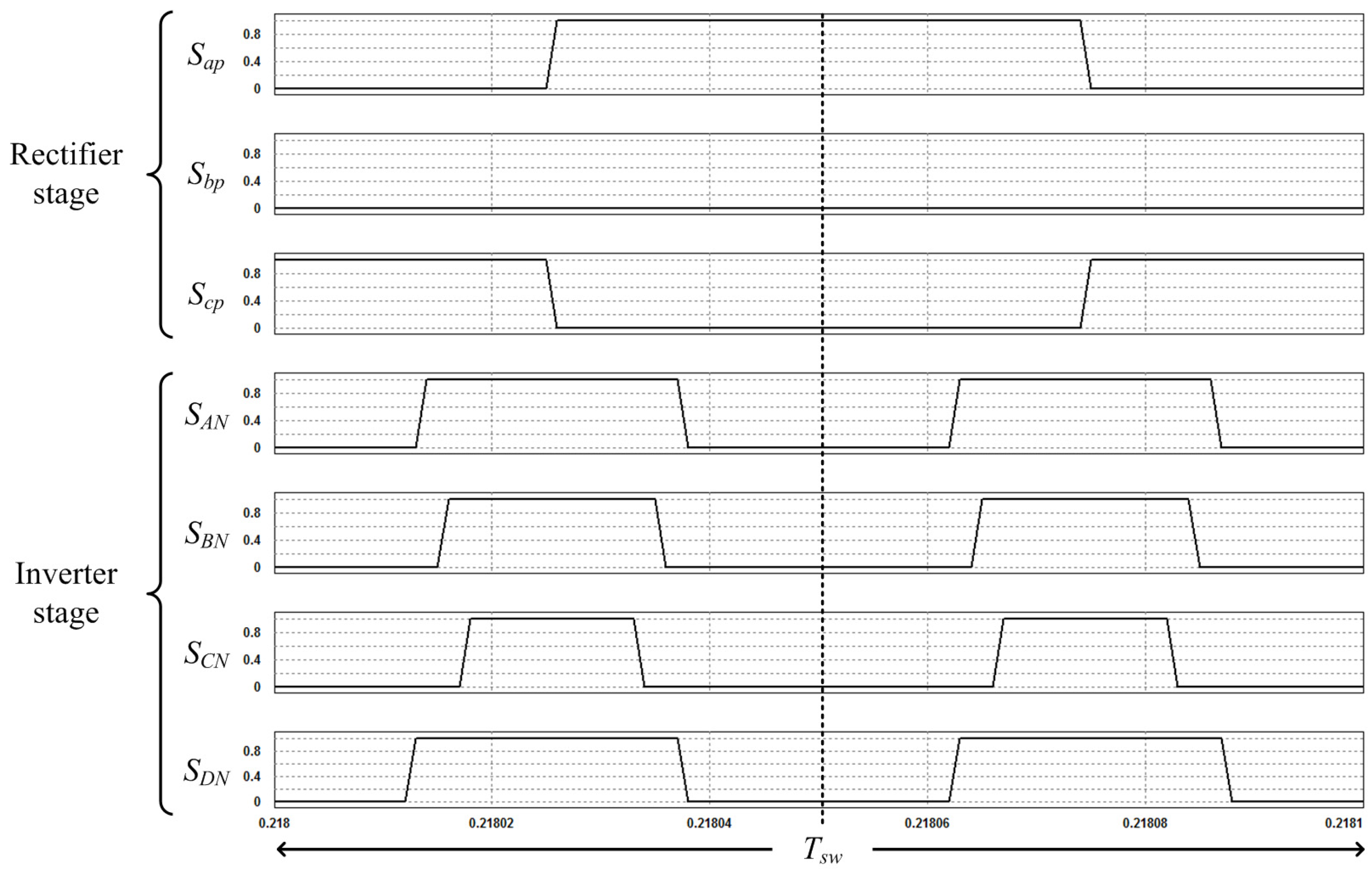
The combination of the switching patterns of the rectifier stage and the inverter stage for the dual outputs is shown in Figure 7. The inverter stage is switched both into the free-wheeling operation and the rectifier stage, and then, it is commutated at the zero DC-link current. It can also be seen that the inverter stage switching frequency is two times the rectifier stage switching frequency.

Figure 7.
Combination of the switching pattern for the dual outputs in the proposed system.
Figure 7.
Combination of the switching pattern for the dual outputs in the proposed system.
4. Simulation Results
In order to demonstrate the performance of the proposed dual output drive system for the HEV application, a comprehensive simulation study was performed using the PSIM simulation. The performance of the system based on the VSMC has been tested using the three-phase input stage, input filter, VSMC and the two output stages as in Figure 4. The three-phase input stage and the input filter are composed of a three-phase voltage source and an inductor-capacitor filter, respectively. The two output stages are composed of a three-phase resistor-inductor load and a single-phase resistor-inductor load.
The simulation parameters indicated in Figure 4 are shown in Table 1. In this regard, Vin of the three-phase input stage means the line-to-line voltage. Additionally, the parameters of the input filter were considered as Lf = 2 mH with the resistor Rf = 0.1 Ω added for damping, and Cf = 7 μF for filtering. These values were not optimized, however, they were rather chosen from the values available in the laboratory.

Table 1.
System parameters.
| Classification | Value | |
|---|---|---|
| Input parameters | 3-phase input stage | Vin = 220 Vrms, fin = 60 Hz |
| Input filter | Lf = 2 mH, Cf = 7 μF | |
| Output parameters | 3-phase output stage | Rload1 = 10 Ω, Lload1 = 5 mH |
| 1-phase output stage | Rload2 = 14 Ω, Lload2 = 2 mH |
As mentioned in according to Section 3, the SVPWM is used to modulate the dual output drive system based on the VSMC. In addition, the switching frequency of the VSMC is set to be 10 kHz. In order to perform a closed loop control of the dual output drive system, the vector control strategy is used to control the two loads.
Figure 8 shows the simulation results of the proposed dual output drive system. In detail, Figure 8a shows the three-phase input line-to-line voltages, which are required for the operation of the proposed dual output drive system. The three-phase input voltage source was specified for the simulation verification as 220 Vrms/60 Hz. Figure 8b shows the DC-link voltage provided by the rectifier stage.

Figure 8.
Simulation results of the proposed dual output drive system: (a) three-phase input line-to-line voltages; (b) DC-link voltage.
Figure 8.
Simulation results of the proposed dual output drive system: (a) three-phase input line-to-line voltages; (b) DC-link voltage.
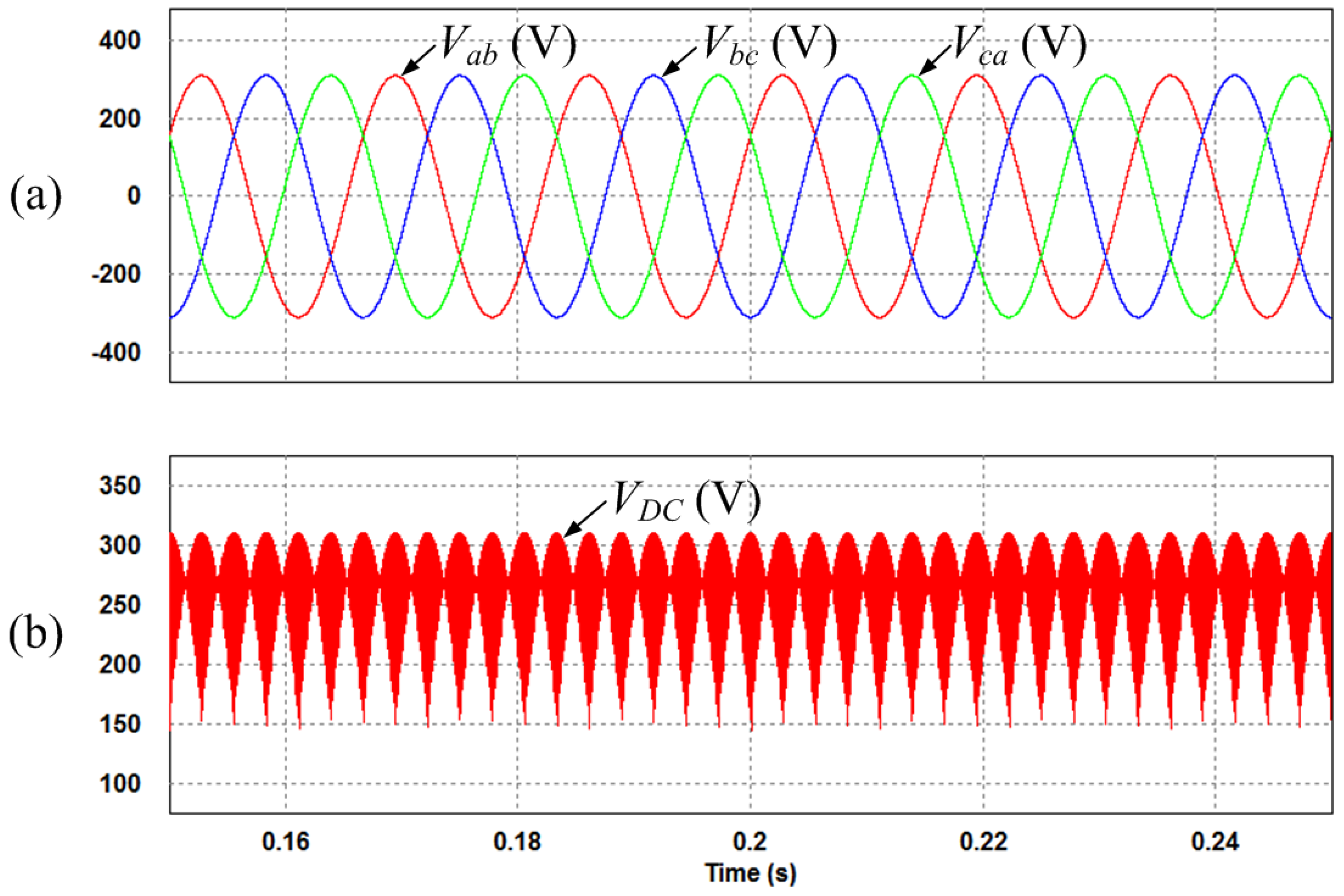
Figure 9 and Figure 10 show the dynamic responses of the three-phase load and the single-phase load. Figure 9a,b show the output line-to-line voltage and the three-phase output currents, respectively, in the three-phase load. The reference current of the three-phase load changed from 5 A/30 Hz to 10 A/60 Hz at 0.2 s. Similarly, Figure 10a,b show the output line-to-line voltage and the single-phase output current, respectively, in the single-phase load. The reference current of the single-phase load changed from 2 A/30 Hz to 5 A/60 Hz at 0.2 s. Figure 9b and Figure 10b show that the currents follow their reference values.

Figure 9.
Simulation results of dynamic response for the three-phase load: (a) output line-to-line voltage; (b) three-phase output currents.
Figure 9.
Simulation results of dynamic response for the three-phase load: (a) output line-to-line voltage; (b) three-phase output currents.
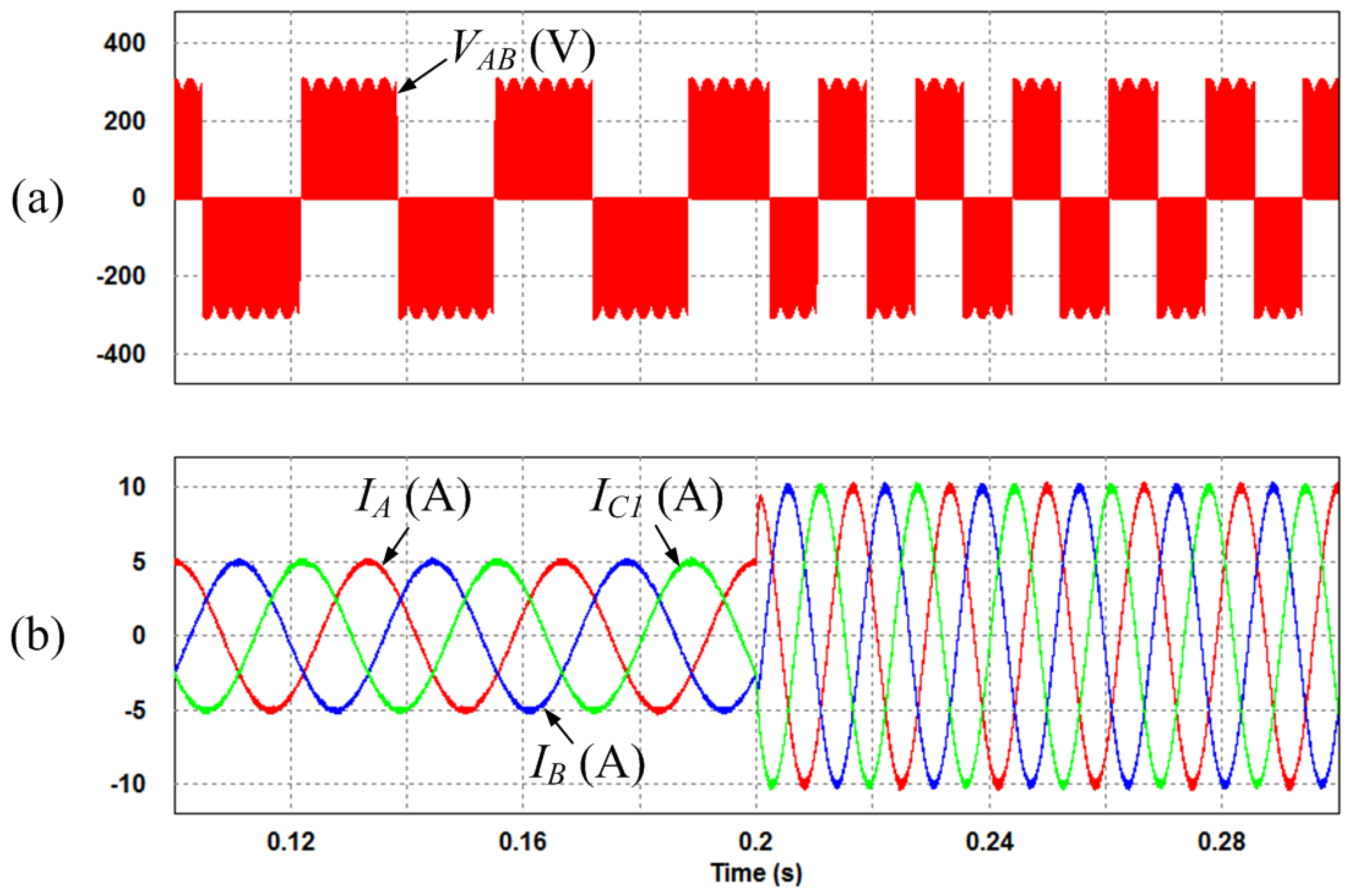

Figure 10.
Simulation results of dynamic response for the single-phase load: (a) output line-to-line voltage; (b) single-phase output current.
Figure 10.
Simulation results of dynamic response for the single-phase load: (a) output line-to-line voltage; (b) single-phase output current.
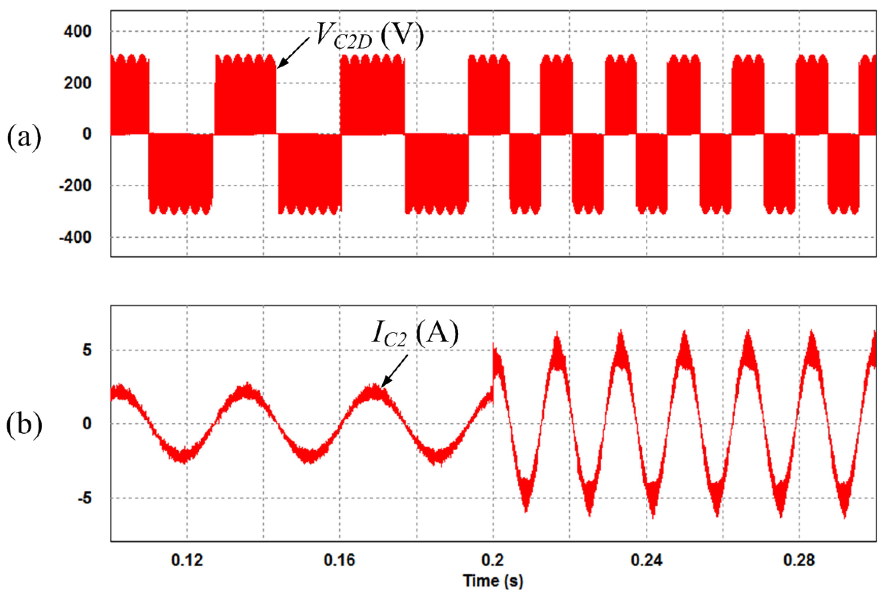
Figure 11 shows the dynamic response of the currents for the dual outputs. In detail, Figure 11a,b show the three-phase output currents and the single-phase output current, respectively. The reference current of the three-phase load changed from 5 A/30 Hz to 10 A/30 Hz at 0.2 s, while the reference current of the single-phase load was maintained constant at 2 A/30 Hz. At 0.3 s, the reference current of the single-phase load changed from 2 A/30 Hz to 5 A/60 Hz, and the frequency of the reference current for the three-phase load increased from 30 Hz to 60 Hz. Finally, at 0.4 s, the reference currents of the three-phase and the single-phase loads changed from 10 A/60 Hz to 5 A/30 Hz, and from 5 A/60 Hz to 2 A/30 Hz, respectively. From these simulation results, it is concluded that the control of the dual output drive system works well with the VSMC in the proposed modulation method.

Figure 11.
Simulation results of dynamic response: (a) output currents in the three-phase load; (b) output current in the single-phase load.
Figure 11.
Simulation results of dynamic response: (a) output currents in the three-phase load; (b) output current in the single-phase load.
5. Experimental Results
In order to demonstrate the proposed dual output drive system and the simulation results, an experiment was conducted in the laboratory. The experimental parameters were identical with the system parameters shown in Table 1.
Figure 12 shows the experimental set, including the control board and power board. Figure 12a shows the control board, which is TMS320C28346 digital signal processor (DSP) board with an FPGA. The proposed modulation strategy is programmed on the DSP board. Figure 12b shows the power board of the conventional SMC composed of the inverter stage and rectifier stage. Finally, the power board of the proposed topology having the dual outputs is shown in Figure 12c. It is designed by installing an additional leg to the conventional SMC. The proposed algorithm was applied in order to verify the performance of this topology as shown in Figure 13.
Figure 14 shows the experimental waveform of the three-phase input line-to-line voltages and the DC-link voltage provided by the rectifier stage. In this case, the three-phase input line-to-line voltages provided by the voltage source of the rectifier stage are 220 Vrms.
Figure 15 shows the output line-to-line voltage and the output currents for the three-phase load. The reference current of the three-phase load changed from 5 A/30 Hz to 10 A/60 Hz. When the reference current of the three-phase load was changed, the value of the output line-to-line voltage was retained in spite of the variation of the reference current; only the frequency changed.

Figure 12.
Experimental set: (a) control board; (b) power board of the conventional SMC; (c) power board of the proposed topology.
Figure 12.
Experimental set: (a) control board; (b) power board of the conventional SMC; (c) power board of the proposed topology.
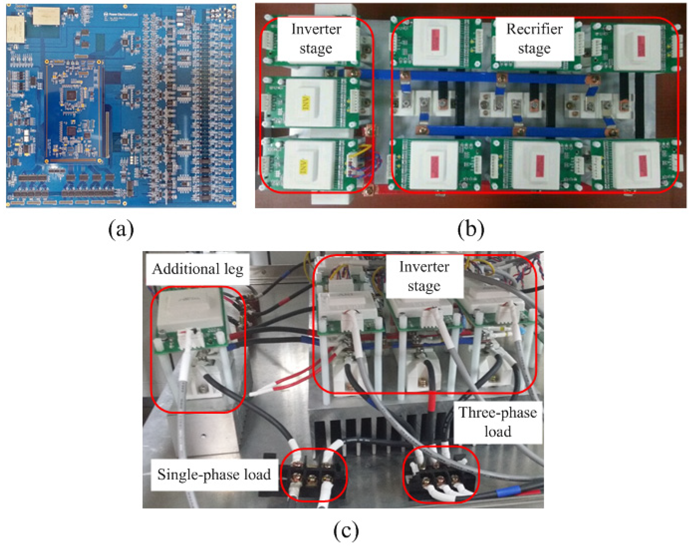

Figure 13.
Block diagram of the experimental set.
Figure 13.
Block diagram of the experimental set.
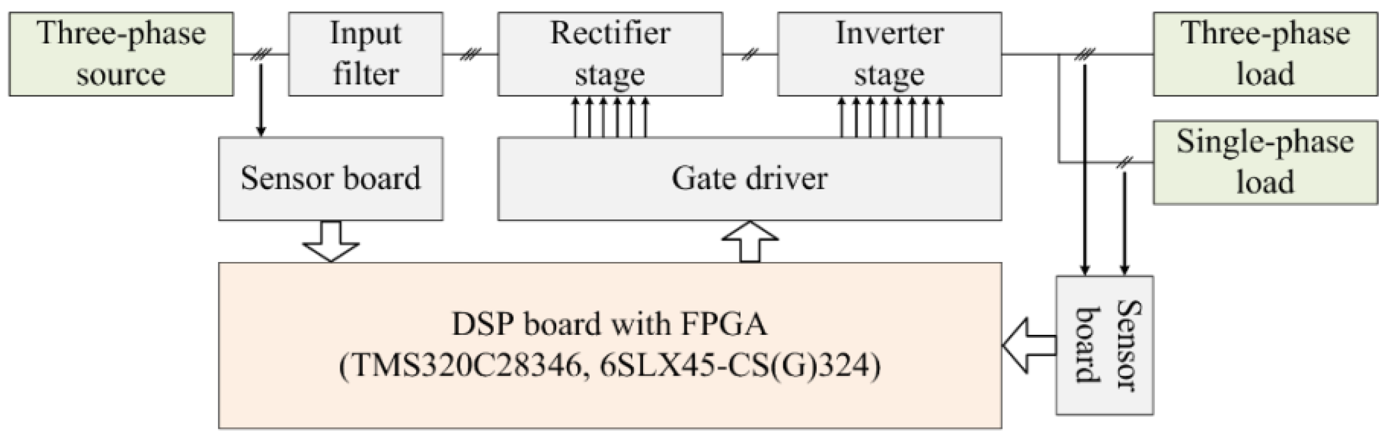

Figure 14.
Experimental waveforms of the three-phase input line-to-line voltages and the DC-link voltage.
Figure 14.
Experimental waveforms of the three-phase input line-to-line voltages and the DC-link voltage.
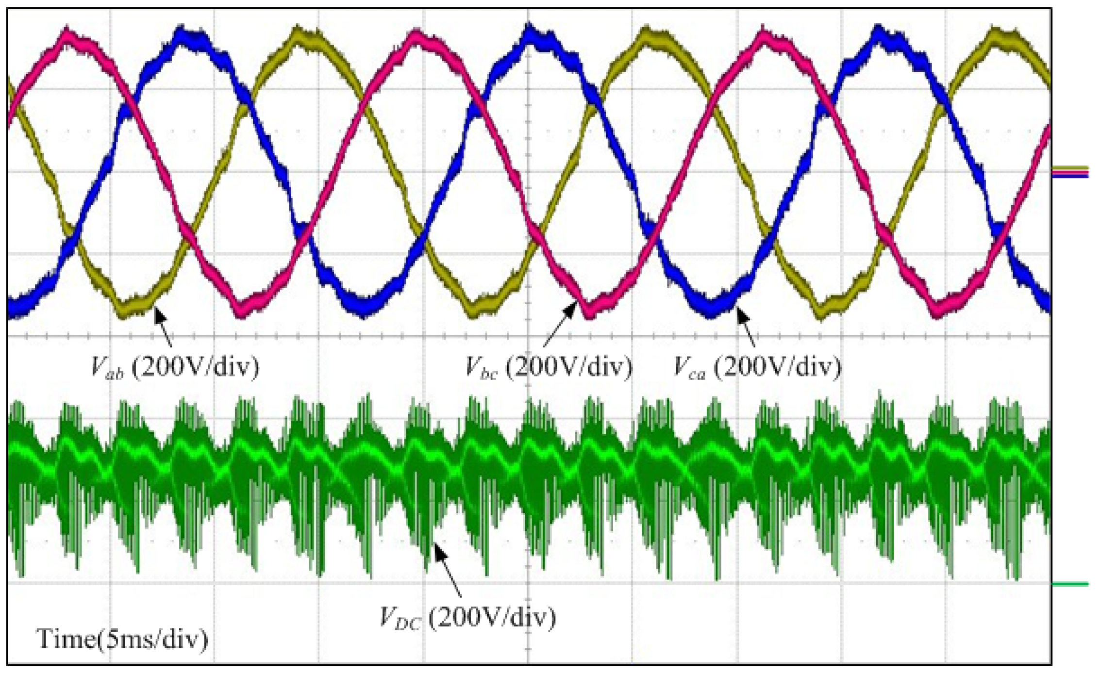

Figure 15.
Experimental waveforms of the output line-to-line voltage and the output currents for the three-phase load.
Figure 15.
Experimental waveforms of the output line-to-line voltage and the output currents for the three-phase load.
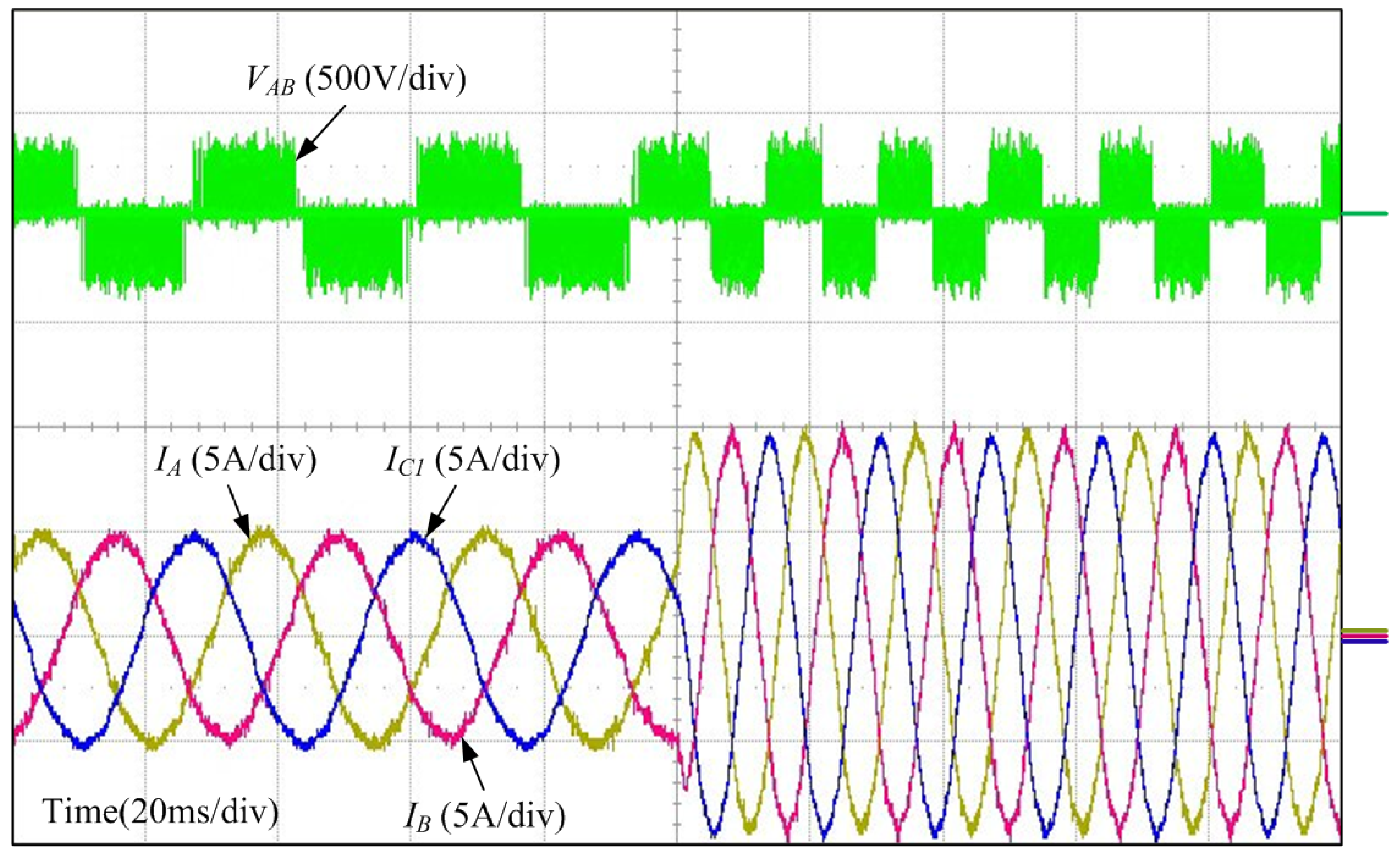
Figure 16 shows the output line-to-line voltage and the output current for the single-phase load. The reference current of the single-phase load changed from 2 A/30 Hz to 5 A/60 Hz. In common with the three-phase load, although the reference current of the single-phase load was changed, the value of the output line-to-line voltage was retained.

Figure 16.
Experimental waveforms of the output line-to-line voltage and the output current for the single-phase load.
Figure 16.
Experimental waveforms of the output line-to-line voltage and the output current for the single-phase load.
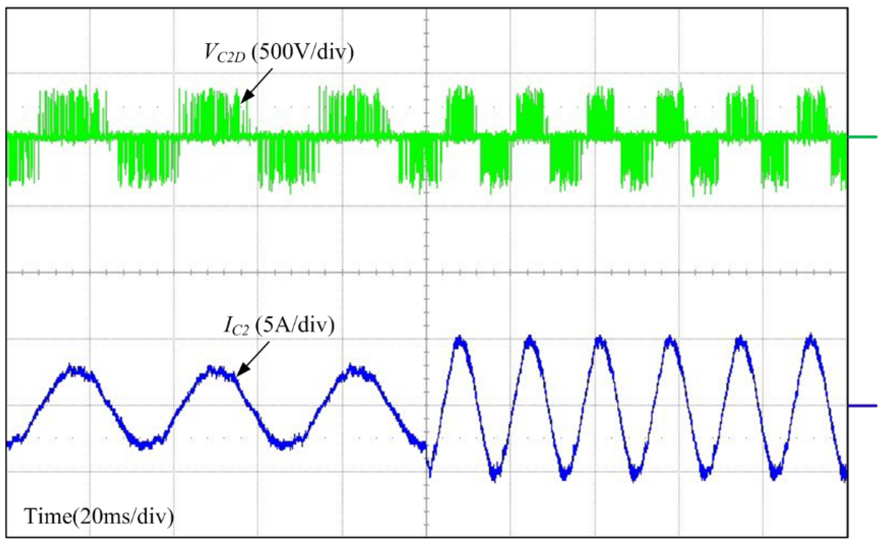
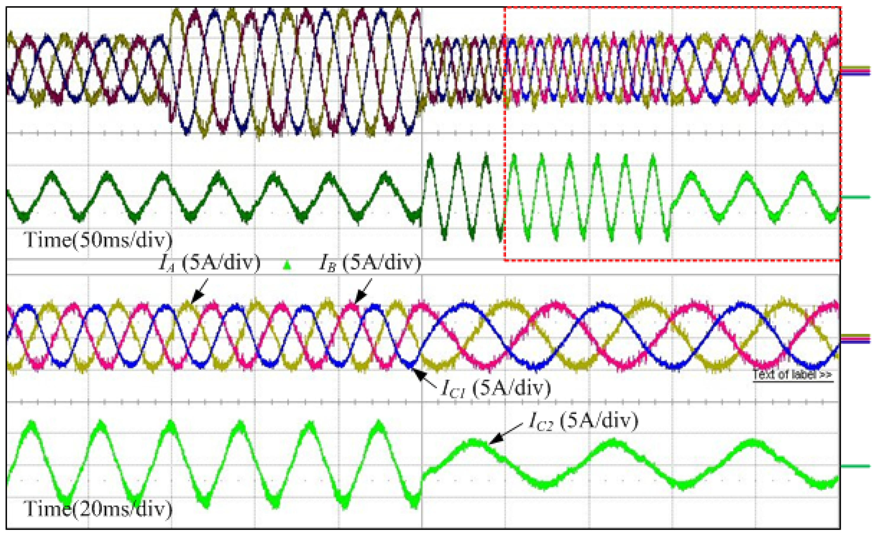
Figure 17 shows the output currents with the dual outputs. The output reference current of the three-phase load changed from 5 A/30 Hz to 10 A/60 Hz. Furthermore, the output reference frequency of the single-phase load changed from 30 Hz to 60 Hz while the reference current of the single-phase load was maintained at 5 A. Figure 18 shows the experimental results with variations of the output reference frequency and current for both the three-phase output and single-phase output. Waveforms related to the variations of the references are shown in Figure 19, Figure 20 and Figure 21. That is, each waveform is magnified for each of the variation of the references.

Figure 17.
Experimental waveforms of the output currents with the dual outputs.
Figure 17.
Experimental waveforms of the output currents with the dual outputs.
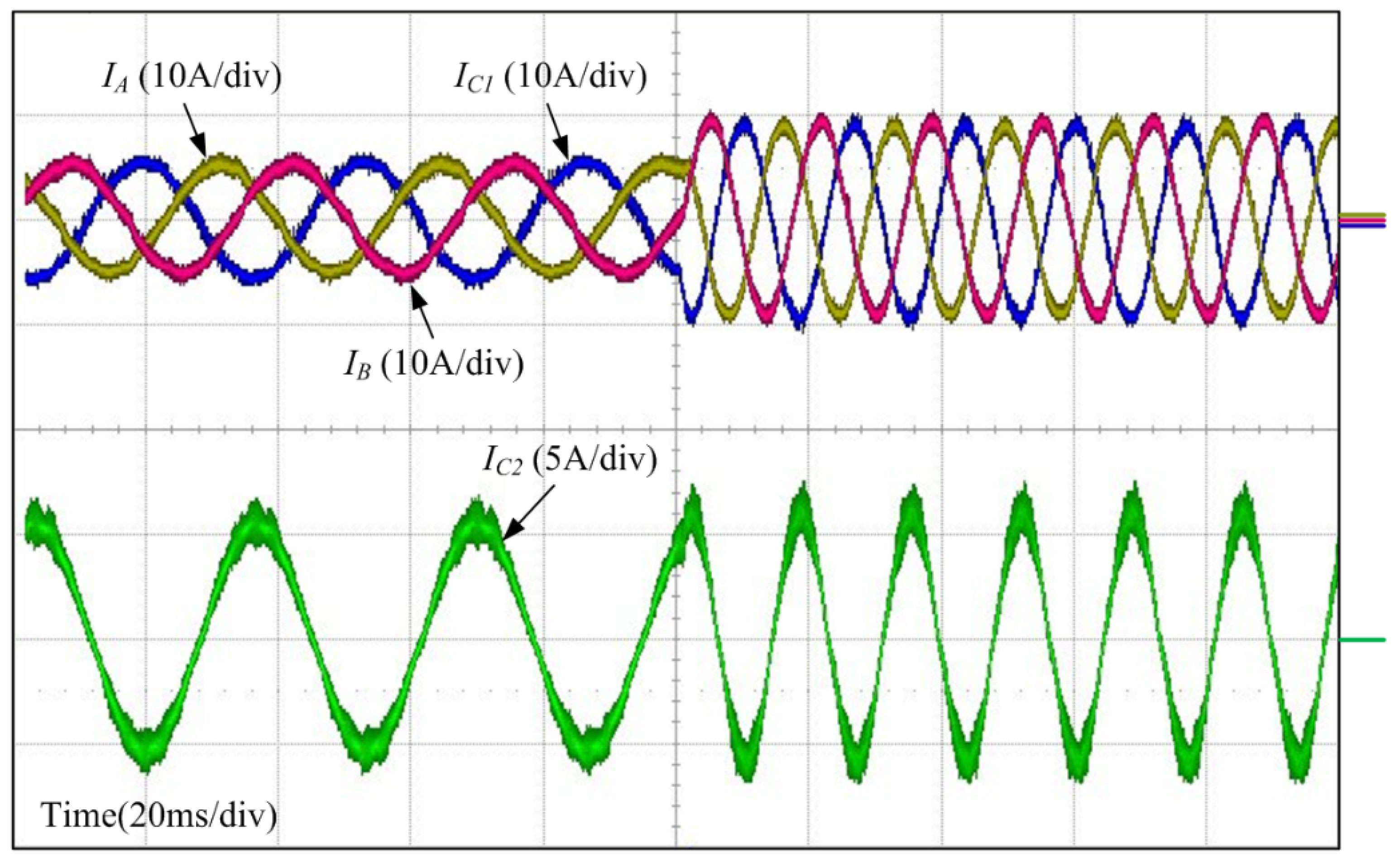

Figure 18.
Experimental waveforms of the three-phase and single-phase output currents, controlled by the independent references.
Figure 18.
Experimental waveforms of the three-phase and single-phase output currents, controlled by the independent references.
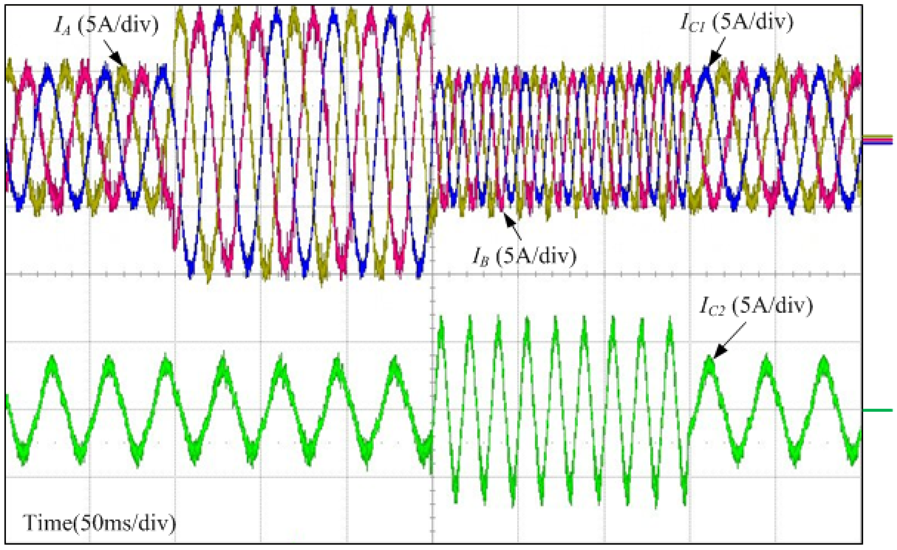
Figure 19 shows the magnified waveforms of the output currents with the dual outputs. The reference current of the three-phase load changed from 5 A/30 Hz to 10 A/30 Hz. However, the reference current of the single-phase load was maintained at 2 A/30 Hz.

Figure 19.
Experimental waveforms magnified for the first variation of the references.
Figure 19.
Experimental waveforms magnified for the first variation of the references.
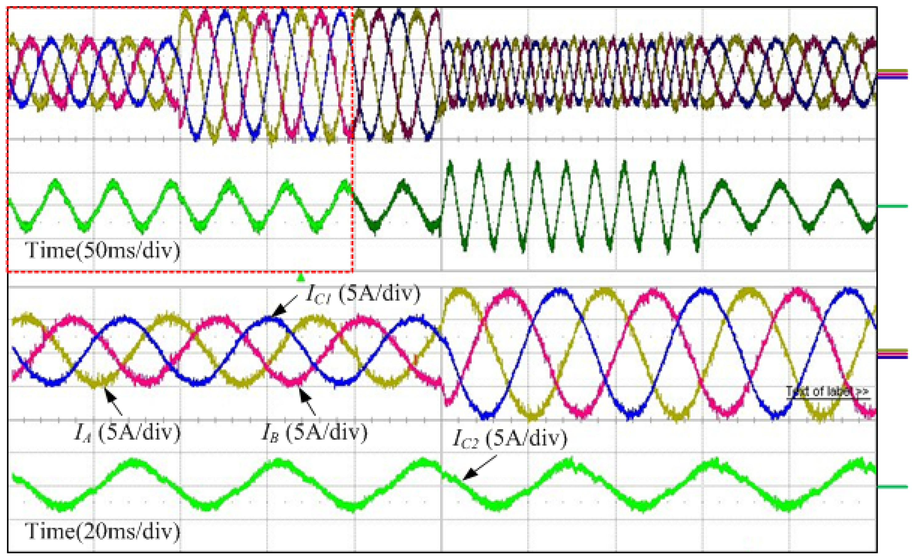
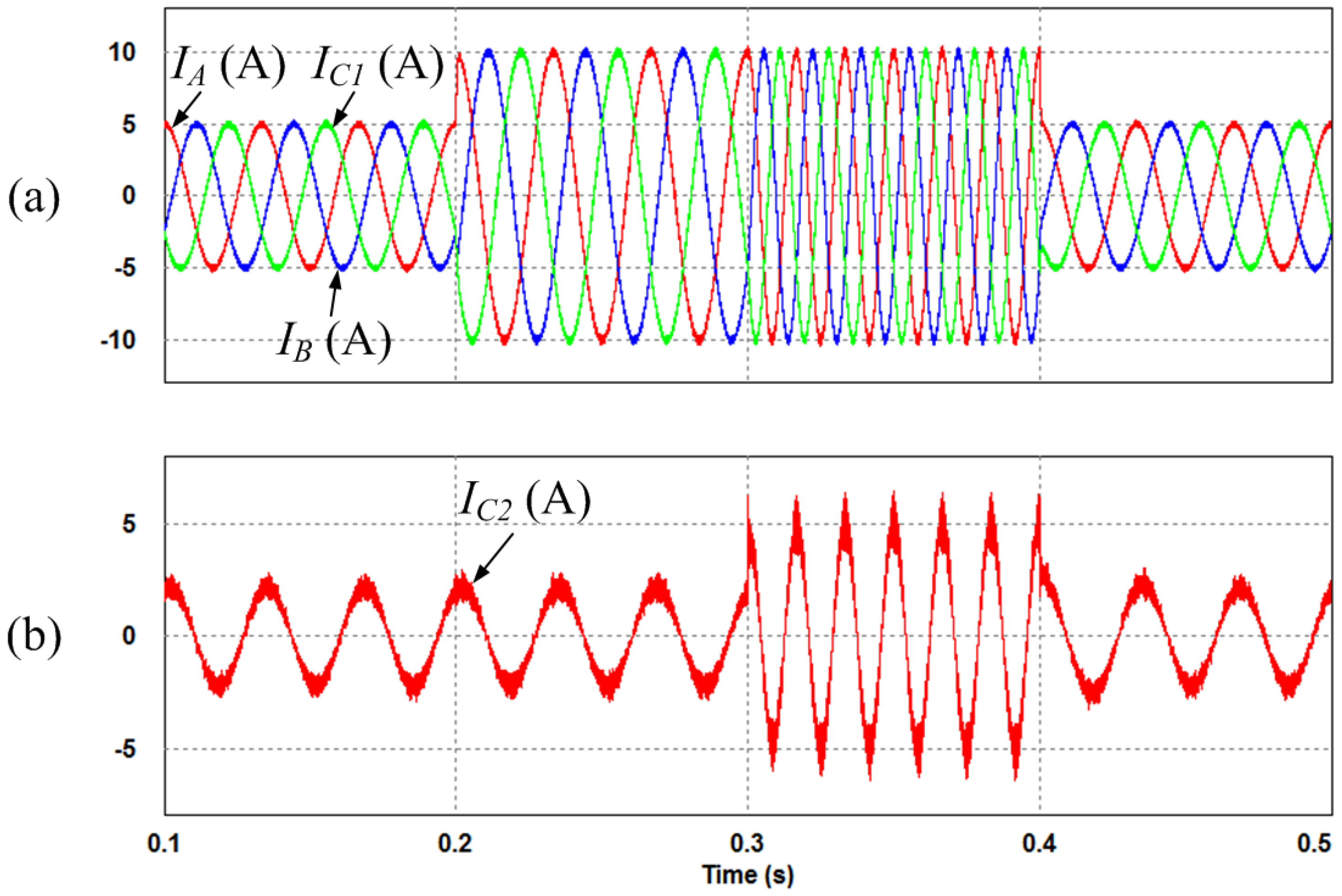
Figure 20 shows the magnified waveforms for the second variation of the references. The reference current of the three-phase load changed from 10 A/30 Hz to 5 A/60 Hz. In addition, the reference current of the single-phase load changed from 2 A/30 Hz to 5 A/60 Hz.

Figure 20.
Experimental waveforms magnified for the second variation of the references.
Figure 20.
Experimental waveforms magnified for the second variation of the references.
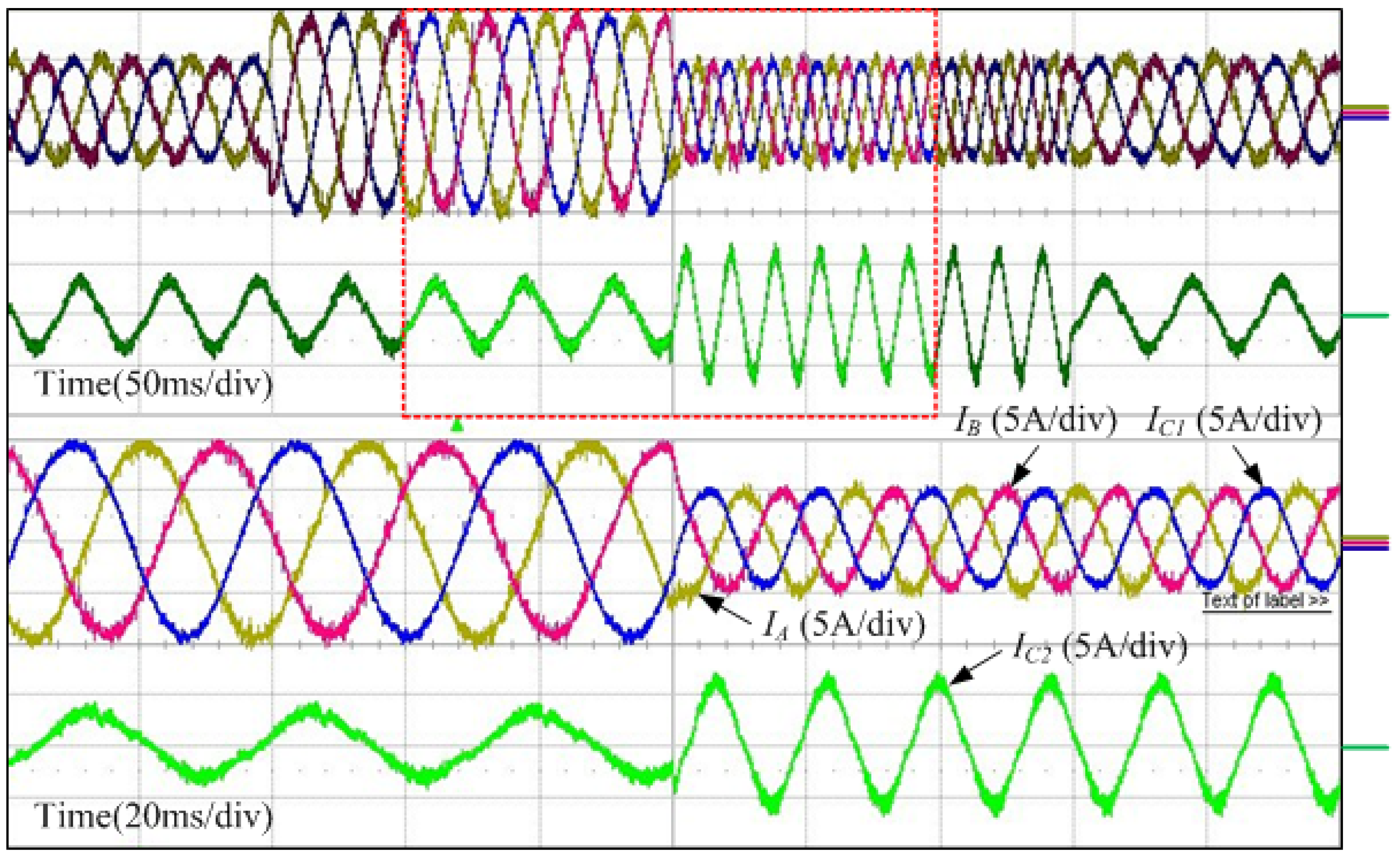
Figure 21 shows the magnified waveforms of the third variation of the references. The reference current of the three-phase load changed from 5 A/60 Hz to 5 A/30 Hz, and the reference current of the single-phase load changed from 5 A/60 Hz to 2 A/30 Hz. According to the experimental results shown in Figure 18, it is demonstrated that the three-phase output current and the single-phase output current are controlled using individual references. In other words, the three-phase load and the single-phase load are controlled independently.

Figure 21.
Experimental waveforms magnified for the third variation of the references.
Figure 21.
Experimental waveforms magnified for the third variation of the references.
6. Conclusions
The proposed IMC for the HEV application with three-phase and single-phase outputs is presented. Additionally, the topology and the modulation strategies in order to control the three-phase and the single-phase loads with vector control are presented. This proposed system is highly potential for various applications where load and converter redundancy may be required to improve availability. This type of multi-drive system can be used in many industrial and aerospace applications. In particular, this system can be used in the HEV application. In this regard, the three-phase load and the single-phase load can be applied the traction motor and the compressor motor in the HEV application. The application of this system as a power conversion system for the HEV has crucial advantages. Because the IMC has no energy storage elements such as capacitors in the DC-link, the system guarantees a long lifetime. Furthermore, through the parallel operation of the dual outputs, the volume of the system is decreased. The performance of the topology and its control method is demonstrated by simulation and experimental results. The three-phase output current and the single-phase output current are controlled using independent references.
Acknowledgments
This work was supported by the Human Resources Development of the Korea Institute of Energy Technology Evaluation and Planning (KETEP) grant funded by the Korea government Ministry of Knowledge Economy (No. 20134030200310) and by Basic Science Research Program through the National Research Foundation of Korea (NRF) funded by the Ministry of Education (2013R1A1A2A10006090).
Author Contributions
Kyo-Beum Lee provided guidance and supervision. Eunsil Lee conceived the idea of this paper and performed the simulation. Yeongsu Bak implemented the main research, performed the experiment, wrote the paper and revised the manuscript as well. All authors have equally contributed to the simulation analysis, experiment and result discussions.
Conflicts of Interest
The authors declare no conflict of interest.
References
- Suh, I.S.; Lee, K.; Lee, M. Dynamic model and control algorithm of HVAC system for dynamic wireless charging EV application. In Proceedings of the IEEE International Electric Machines & Drives Conference (IEMDC), Chicago, IL, USA, 12–15 May 2013; pp. 241–246.
- Rind, S.; Ren, Y.; Jiang, L. Traction motors and speed estimation techniques for sensorless control of electric vehicles: A review. In Proceedings of the 49th International Universities Power Engineering Conference (UPEC), Cluj-Napoca, Romania, 2–5 September 2014; pp. 1–6.
- Heydari, M.; Varjani, A.Y.; Mohamadian, M.; Fatemi, A. A novel dual-output six-switch three-phase inverter. In Proceedings of the 37th Annual Conference on IEEE Industrial Electronics Society Industrial Electronics Conference (IECON), Melbourne, VIC, Australia, 7–10 November 2011; pp. 1109–1114.
- Ledezma, E.; McGrath, B.; Munoz, A.; Lipo, T.A. Dual AC-drive system with a reduced switch count. IEEE Trans. Ind. Appl. 2001, 37, 1325–1333. [Google Scholar] [CrossRef]
- Najmi, E.S.; Rajaei, A.H.; Mohamadian, M.; Dehghan, S.M. A novel dual output six switch inverter for driving two phase induction motor. In Proceedings of the 4th Power Electronics, Drive Systems and Technologies Conference (PEDSTC), Tehran, Iran, 13–14 February 2013; pp. 248–253.
- Dehghan, S.M.; Mohamadian, M.; Yazdian, A.; Ashrafzadeh, F. A dual-input dual-output z-source inverter. IEEE Trans. Power Electron. 2010, 25, 360–368. [Google Scholar] [CrossRef]
- Bak, Y.; Lee, E.; Lee, K.B. An indirect matrix converter for dual output AC-Drive system with reduced number of power transistors. In Proceedings of the IEEE Conference on Energy Conversion (CENCON), Johor Bahru, Malaysia, 13–14 October 2014; pp. 360–364.
- Jeong, H.G.; Ro, H.S.; Lee, K.B. An improved maximum power point tracking method for wind power systems. Energies 2012, 5, 1339–1354. [Google Scholar] [CrossRef]
- Lee, J.S.; Lee, K.B.; Blaabjerg, F. Open-switch fault detection method of a back-to-back converter using NPC topology for wind turbine systems. IEEE Trans. Ind. Appl. 2015, 51, 325–335. [Google Scholar] [CrossRef]
- Lee, K.B.; Blaabjerg, F. Simple power control for sensorless induction motor drives fed by a matrix converter. IEEE Trans. Energy Convers. 2008, 23, 781–788. [Google Scholar] [CrossRef]
- Metidji, B.; Taib, N.; Baghli, L.; Rekioua, T.; Bacha, S. Novel single current sensor topology for venturini controlled direct matrix converters. IEEE Trans. Power Electron. 2013, 28, 3509–3516. [Google Scholar] [CrossRef]
- Friedli, T.; Kolar, J.W.; Rodriguez, J.; Wheeler, P.W. Comparative evaluation of three-phase AC-AC matrix converter and voltage DC-link back-to-back converter systems. IEEE Trans. Ind. Electron. 2012, 59, 4487–4510. [Google Scholar] [CrossRef]
- Kolar, J.W.; Schafmeister, F.; Round, S.D.; Ertl, H. Novel three-phase AC-AC sparse matrix converters. IEEE Trans. Power Electron. 2007, 22, 1649–1661. [Google Scholar] [CrossRef]
- Lee, E.; Lee, K.B.; Lim, J.S.; Lee, Y.; Song, J.H. Predictive current control for a sparse matrix converter. In Proceedings of the 7th International Power Electronics and Motion Control Conference (IPEMC), Harbin, China, 2–5 June 2012; pp. 36–40.
- Lee, E.; Lee, K.B.; Lee, Y.; Song, J.H. High performance current controller for sparse matrix converter based on model predictive control. J. Electr. Eng. Technol. 2013, 8, 1138–1145. [Google Scholar] [CrossRef]
- Kumar, D.; Wheeler, P.; Clare, J.; Kim, T.W. Multi-motor drive system based on a two-stage direct power conversion topology for aerospace applications. In Proceedings of the 4th IET Conference on Power Electronics, Machines and Drives (PEMD), York, UK, 2–4 April 2008; pp. 607–610.
- Liu, X.; Wang, P.; Loh, P.C.; Blaabjerg, F. A compact three-phase single-input/dual-output matrix converter. IEEE Trans. Ind. Electron. 2012, 59, 6–16. [Google Scholar] [CrossRef]
- Milan, G.; Dehghan, S.M.; Biabani, M.; Sahraneshin, S.; Mohamadian, M. Single-input-dual-output matrix converters and space vector modulation. In Proceedings of the 20th Iranian Conference on Electrical Engineering (ICEE), Tehran, Iran, 15–17 May 2012; pp. 569–574.
- Nguyen, T.D.; Lee, H.H. Dual three-phase indirect matrix converter with carrier-based PWM method. IEEE Trans. Power Electron. 2014, 29, 569–581. [Google Scholar] [CrossRef]
- Nguyen, T.D.; Lee, H.H. Space vector modulation for single-input dual-output indirect matrix converter. In Proceedings of the 38th Annual Conference on IEEE Industrial Electronics Society Industrial Electronics Conference (IECON), Montreal, QC, Canada, 25–28 October 2012; pp. 6111–6116.
- Kwak, S.; Kim, T.; Park, G. Phase-redundant-based reliable direct AC/AC converter drive for series hybrid off-highway heavy electric vehicles. IEEE Trans. Veh. Technol. 2010, 59, 2674–2688. [Google Scholar] [CrossRef]
- Su, G.J.; Tang, L. Current source inverter based traction drive for EV battery charging applications. In Proceedings of the IEEE Vehicle Power and Propulsion Conference (VPPC), Chicago, IL, USA, 6–9 September 2011; pp. 1–6.
- Kwak, S.; Kim, T.; Vodyakho, O. Four-leg based matrix converter with fault resilient structures and controls for electric vehicle and propulsion systems. In Proceedings of the IEEE Vehicle Power and Propulsion Conference (VPPC), Arlington, TX, USA, 9–12 September 2007; pp. 519–523.
- Khanchoul, M.; Krebs, G.; Marchand, C. Improvement of a permanent magnet synchronous motor for an electrical compressor. In Proceedings of the 37th Annual Conference on IEEE Industrial Electronics Society Industrial Electronics Conference (IECON), Melbourne, VIC, Australia, 7–10 November 2011; pp. 4583–4588.
- Su, G.J.; Hsu, J.S. An integrated traction and compressor drive system for EV/HEV applications. In Proceedings of the 20th Annual IEEE Applied Power Electronics Conference and Exposition (APEC), Austin, TX, USA, 6–10 March 2005; pp. 719–725.
- Su, G.J.; Hsu, J.S. A five-leg inverter for driving a traction motor and a compressor motor. IEEE Trans. Power Electron. 2006, 21, 687–692. [Google Scholar] [CrossRef]
© 2015 by the authors; licensee MDPI, Basel, Switzerland. This article is an open access article distributed under the terms and conditions of the Creative Commons Attribution license (http://creativecommons.org/licenses/by/4.0/).