3.1. Simulation Results
In order to verify the previously described theory, simulations have been performed on the Matlab/Simulink platform.
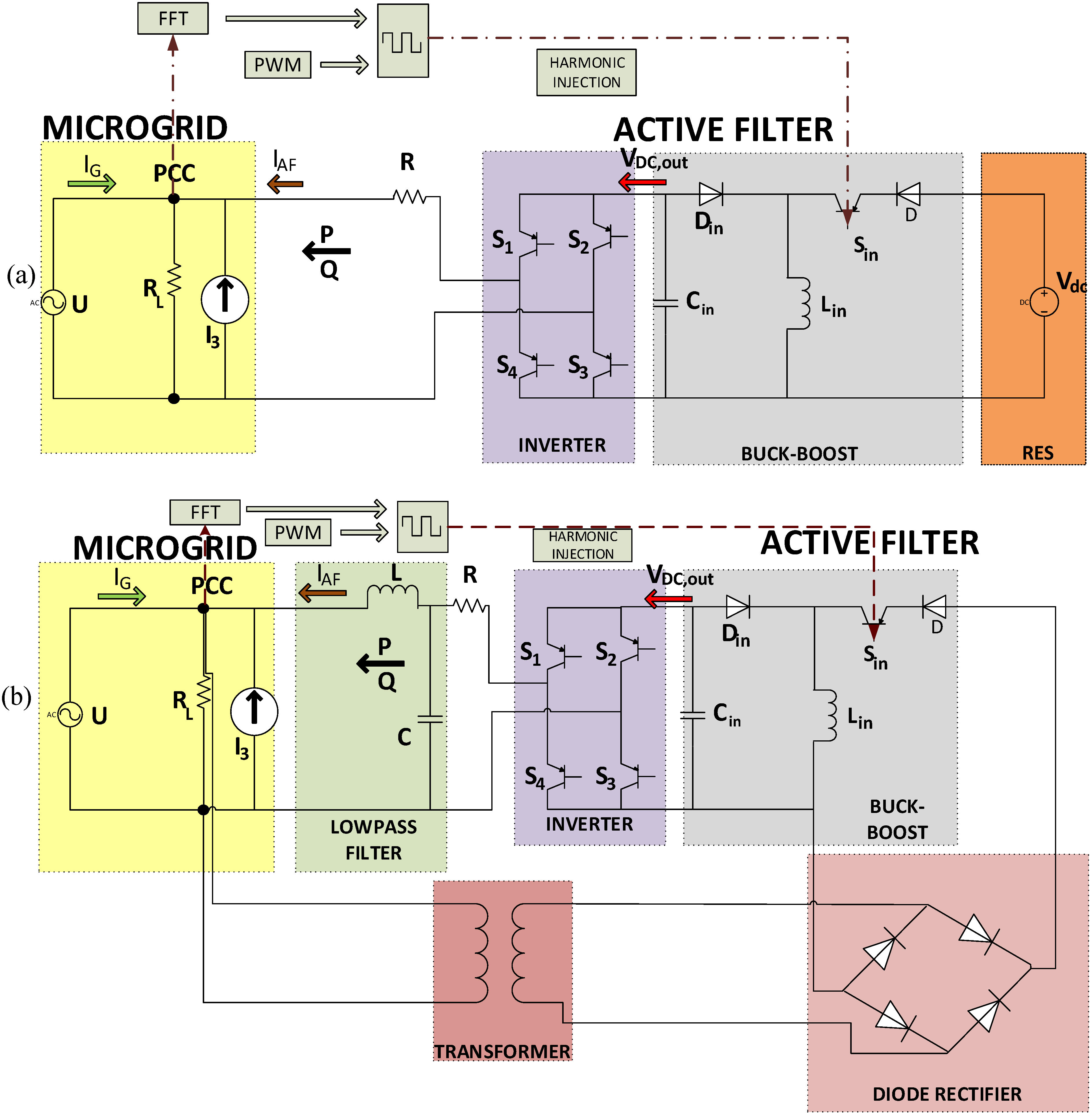
The current harmonic distortion in the studied grid was simulated by a controlled current source. This current source was selected to inject a 3rd harmonic distortion to the PCC of about 15% of the fundamental. As a result a significantly current distorted grid was simulated. The 3rd harmonic was randomly selected for compensation, as a difficult situation. Usually in 3-phase systems, 3rd harmonic distortion is dealt with Y-Delta transformers. However there are many cases, especially in distribution systems, that it is obligatory to use Y-Y transformers. The proposed method would avoid the cost and the space inconvenience of a bulky transformer in 3-phase applications. However a 3-phase system is not studied in this paper. The system studied here is a single-phase microgrid. This harmonic compensation method is the proposed solution for single-phase systems.
A resistance (RL) has been placed as a load at the PCC, in order to avoid any passive load filtering, or generally any affection of the load in reactive power flow study. Insulated-Gate Bipolar Transistors (IGBTs) have been simulated as semiconductors for both the buck-boost converter and the inverter. Two similar diodes have been used for the buck-boost converter. Its inductance has been selected to be as low as 1 mH and the capacitor Cin has been selected to be only 10 μF. Capacitor’s value is quite small compared with capacitances used in similar applications, which are several mF.
The switching frequency of the buck-boost converter was set at 20 kHz (fbb). This particular frequency was selected mainly for three reasons. Firstly, the selected frequency is above acoustic frequencies in order to prevent any disturbance of the user noise. Secondly, this frequency is high enough that there will be filtering by the converter’s passive elements. Finally, this value is a tradeoff between the abovementioned requirements and moderate switching losses. The switching frequency of the inverter was set at 50Hz (finv), as it has to match the voltage frequency at the PCC. The inverter is being connected to the PCC through a 1 Ω resistance (R) and a low pass LC filter (only in the second case). The use of this filter will be explained in the second case. Resistance R is used primarily to avoid resonances. These resonances are caused by the voltage source behavior of the proposed active filter. This voltage cannot be directly connected to the grid voltage at the PCC, because resonances and spikes are created. The use of this small resistance dampens these resonances that deteriorate the waveforms. This situation can be improved by an appropriate control action but this issue is still under investigation. The current harmonic reduction at grid’s current is being feasible due to the total current ejected by the proposed active filter at the PCC ().
The above mentioned control and circuitry parameters are gathered to
Table 1.
Two cases were studied. At first the dc voltage needed for the operation of the buck-boost converter was created by a 300 V dc source. This dc source could be a RES or a DG. In such a case, the RES is not only able to provide the reactive power needed for the current harmonic reduction, but also injects its active power to the grid, making the proposed topology suitable for real RES connected to the grid. The simulated system at this case is shown in
Figure 1a.
In this case the proposed active filter consisting of a RES, the buck-boost converter and the inverter connected back-to-back, is used in order to alleviate the current harmonic distortion of the grid. As mentioned before the goal is to reduce the harmonic distortion of the current
below the 5% threshold dictated by standards. Grid’s current
, its THD and its 3rd harmonic component are being displayed in
Figure 5a–c.
Table 1.
Control and circuitry parameters of the studied system.
Table 1.
Control and circuitry parameters of the studied system.
| Quantity | Symbol | Value |
|---|
| Resistance at the PCC | RL | 70 Ω |
| Resistance at the interconnection | R | 1 Ω |
| Buck-boost converter’s inductance | Lin | 1 mH |
| Buck-boost converter’s capacitance | Cin | 10 μF |
| Inductance of the low pass filter (2nd case) | L | 10 mH |
| Capacitance of the low pass filter (2nd case) | C | 7 μF |
| Switching frequency of the buck-boost converter | fbb | 20 kHz |
| Switching frequency of the inverter | finv | 50 Hz |
| DC voltage of the RES (1st case) | Vdc | 300 V |
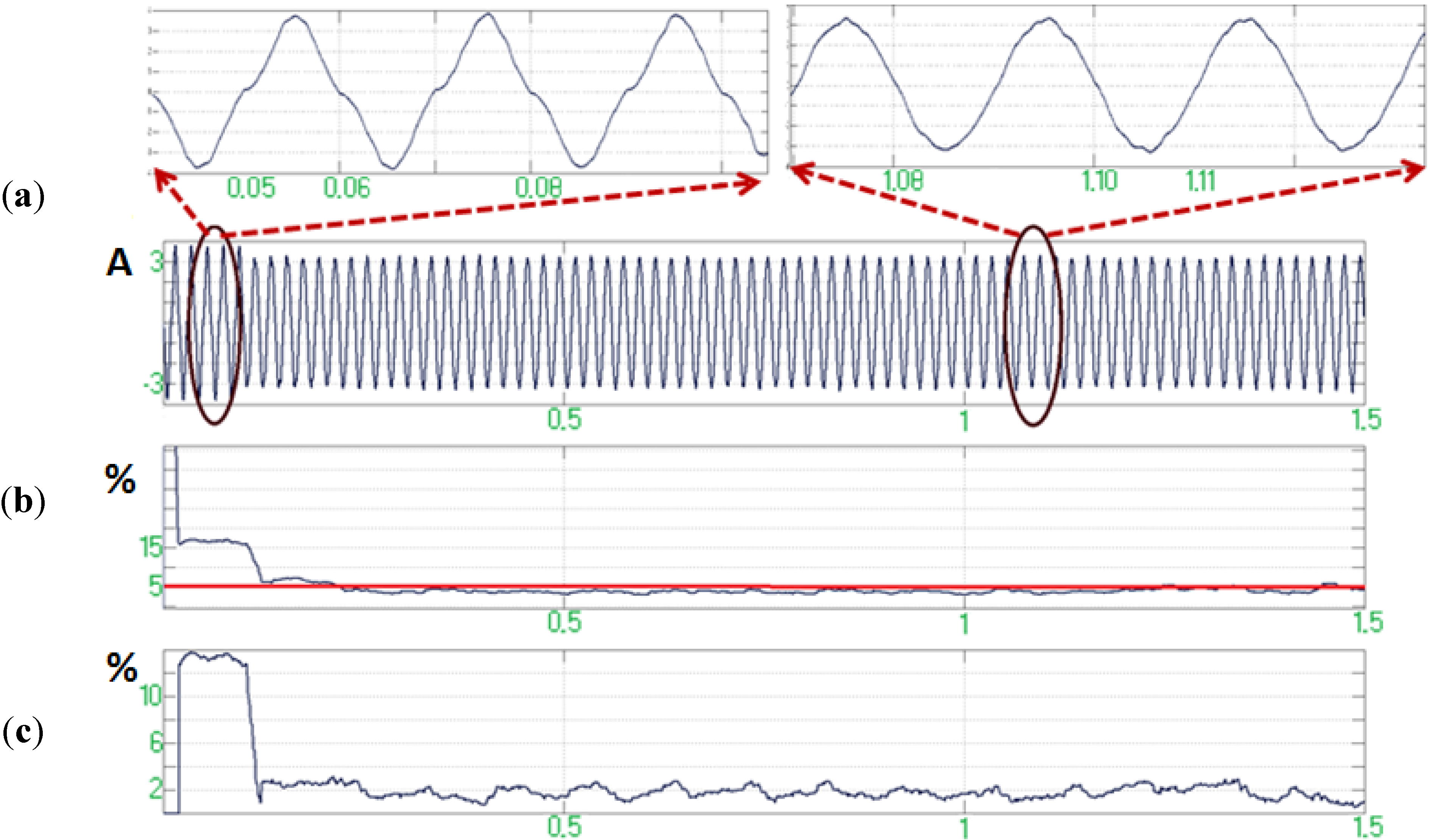
Figure 5.
(a) Grid’s current ; (b) Grid’s current THD; (c) Grid’s current 3rd harmonic component in the first case.
Figure 5.
(a) Grid’s current ; (b) Grid’s current THD; (c) Grid’s current 3rd harmonic component in the first case.
It can be seen in
Figure 5 that the proposed active filter, after a short transient time (not longer than 4–5 cycles), achieves harmonic reduction at the grid current
, compensating the THD below the 5% threshold, exhibiting satisfying behavior. In this case a low pass filter is not necessary as there are no non-linear loads or devices which would create higher high-order harmonics.
In the second case the proposed topology is used as a self-healing active filter. The topology of the studied system is shown in
Figure 1b. In this case no dc source such as RES or DG is used. The necessary for the operation of the buck-boost converter dc voltage is produced by the rectified ac voltage of the microgrid at the PCC. More specifically, the ac voltage of the PCC is being fed to a simple diode rectifier through a one-phase transformer. This transformer was used in order to provide isolation between the proposed active filter and the grid at the input side of our topology. The diode rectifier provides dc voltage for the operation of the buck-boost converter. This dc voltage is being fed to the buck-boost converter and the harmonic cancellation happens as explained in
Section 2.2. The selected diodes are similar to these used at the buck-boost topology.
In this case the harmonic cancellation is more difficult, because except from the already existing high-order harmonic distortion introduced by the current control source, more high-order distortion occurs due to the operation of the diode rectifier as well as the inductance of the transformer. As a result the THD before the initiation of the cancellation method is much higher than 15% that was in the first case, when the active filter had to face only the harmonic distortion produced by the controlled current source. For this reason an LC low pass filter is used after the polarity swapping inverter so that the higher high-order harmonics are suppressed. The values used are 10 mH and 7 μF respectively. Grid’s current
, its THD and its 3rd harmonic component are illustrated in
Figure 6a–c.
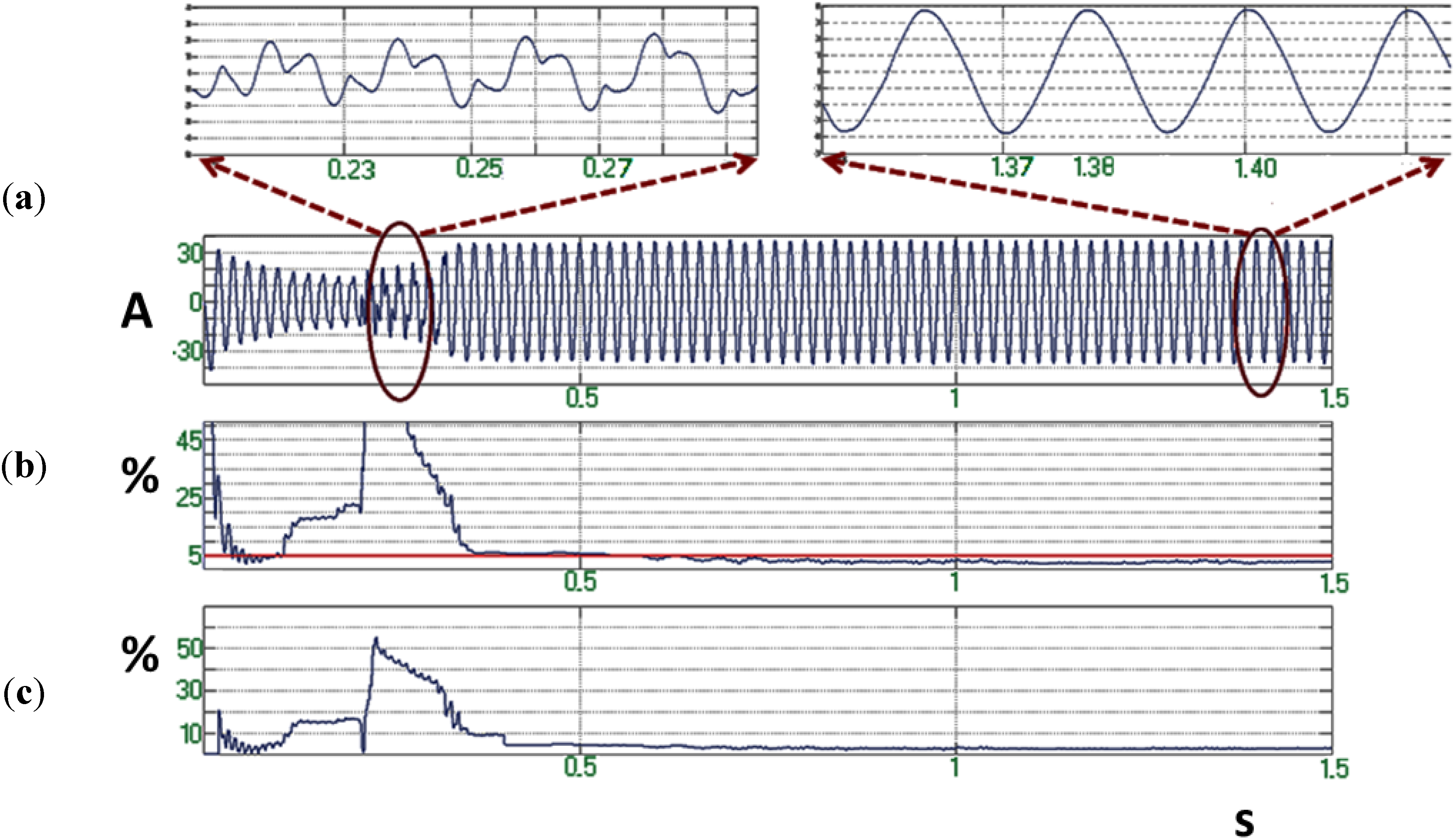
Figure 6.
(a) Grid’s current ; (b) Grid’s current THD; (c) Grid’s current 3rd harmonic component in the second case.
Figure 6.
(a) Grid’s current ; (b) Grid’s current THD; (c) Grid’s current 3rd harmonic component in the second case.
As it can be seen in
Figure 6 the proposed topology exhibits again satisfying behavior as it reduces the harmonic content of grid’s current
below 5%. Here the transient time is longer than in the previous case (approximately 0.25–0.3 s). This is normal because in this case the active filter had to face a more severe harmonic distortion, due to the greater magnitude and spectrum of harmonics. It can be concluded that in this case the active filter manages to reduce not only the already existing current harmonics (created by the controlled current source), but also the harmonic distortion created by the operation of the other parts of the studied system.
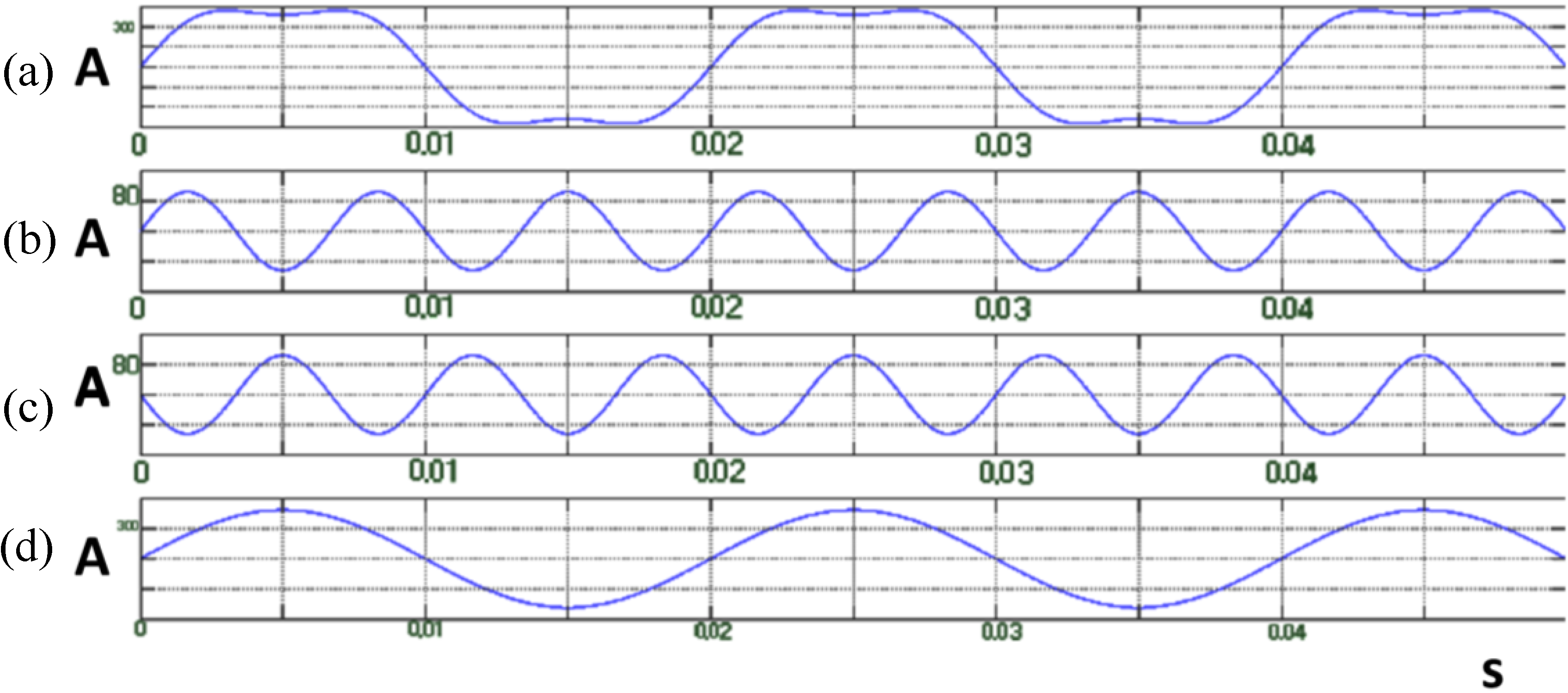
From both previous cases it can be seen that while the studied grid is distorted only by a 3rd harmonic and the 3rd harmonic component of the grid’s current is in both cases reduced below 2%, THD remains below but close to 5%. This happens mainly due to active filter’s switching operation and inductances (L)–capacitances (C) interactions between active filter’s components and the inductances and the capacities of the used filters that create higher harmonics (5th, 7th,
etc.). During the second case this phenomenon is more severe due to the diode rectifier, which is a highly non-linear device that creates high-order harmonic components.
Figure 7 verifies this assumption, showing a simulation example of the output current signal, digitally processed, so that the higher order harmonics (5th, 7th,
etc.) are filtered out. It can be seen that in this case the current THD waveform is exactly the same as the 3rd harmonic waveform. This fact verifies the previous assumption about the difference between THD and 3rd harmonic waveforms in the study cases.
Figure 7.
(a) Grid’s current ; (b) Grid’s current THD; (c) Grid’s current 3rd harmonic component with higher harmonics filtering.
Figure 7.
(a) Grid’s current ; (b) Grid’s current THD; (c) Grid’s current 3rd harmonic component with higher harmonics filtering.
3.2. Experimental Results
In order to evaluate the above described simulation results a similar experimental setup was built. The main purpose of this procedure is to experimentally verify the current harmonics compensation capability of the purposed active filter. The system topology simulated in the first case was recreated in the laboratory. The dc voltage source is now a dc power supply. The maximum available dc voltage we can obtain with this setup is 45 V. As a result a transformer with ratio 1:7 was added at the output of the polarity changing inverter, so that an ac voltage with adequate amplitude for grid synchronization is created (230 V rms). The proposed active filter is synchronized with the grid, which is severally distorted due to the existence of non-linear elements. The harmonic spectra are obtained by FFT analysis performed by a TPS2024B 200 MHz oscilloscope (Tektronix, Beaverton, OR, USA). The DSP TMS320F28335 eZdSP (Spectrum Digital, Stafford, TX, USA) acquires the FFT analysis directly from the oscilloscope and performs the harmonic suppression control in the microgrid. The microgrid condition shown in
Figure 8 was studied. In
Figure 8a the voltage and current waveforms of the grid are presented, while in
Figure 8b the harmonic spectrum of the grid current is illustrated and the amount of the 3rd harmonic is shown. As it can be seen, current THD is almost 21% (20.7%) and the 3rd harmonic distortion is almost 15% (14.48%). As a result, current waveform is quite distorted as it can be seen in
Figure 8a.
Figure 8.
(a) Grid’s voltage and current waveforms before harmonic compensation; (b) Grid’s current harmonic spectrum before harmonic compensation.
Figure 8.
(a) Grid’s voltage and current waveforms before harmonic compensation; (b) Grid’s current harmonic spectrum before harmonic compensation.
Initially, harmonic compensation of only 3rd harmonic was performed. The results are presented in
Figure 9.
Figure 9.
(a) Grid’s voltage and current waveforms after compensation of 3rd harmonic; (b) Grid’s current harmonic spectrum after compensation of 3rdharmonic. 3rd harmonic is shown.
Figure 9.
(a) Grid’s voltage and current waveforms after compensation of 3rd harmonic; (b) Grid’s current harmonic spectrum after compensation of 3rdharmonic. 3rd harmonic is shown.
As it can be seen the proposed active filter performs almost perfectly, as it reduces the 3rd harmonic below 1% of the fundamental (0.6036%). As a result the THD is reduced from 20.7% to below 12% (11.8%), but still cannot meet the 5% standards.
Afterwards 5th harmonic cancellation was executed. THD is again around 20%, as no harmonic compensation has occurred and the 5th harmonic distortion is a little over 10% (10.21%). Now harmonic cancellation of only 5th harmonic is executed and the results are shown in
Figure 10.
Figure 10.
(a) Grid’s voltage and current waveforms after compensation of 5th harmonic; (b) Grid’s current harmonic spectrum after compensation of 5th harmonic. 5th harmonic is shown.
Figure 10.
(a) Grid’s voltage and current waveforms after compensation of 5th harmonic; (b) Grid’s current harmonic spectrum after compensation of 5th harmonic. 5th harmonic is shown.
As it can be seen in
Figure 10, the proposed active filter manages to practically eliminate 5th harmonic as it is reduced to 0.1285%. As a result the THD of the grid current is reduced to 16.1%. Thus it can be said that this topology operates again efficiently, but the goal of 5% is not feasible only with 5th harmonic elimination. For generality purposes cancellation of 7th harmonic was executed next. THD is again almost 21% and the 7th harmonic is 8.385%. The results are shown in
Figure 11.
Figure 11.
(a) Grid’s voltage and current waveforms after compensation of 7th harmonic; (b) Grid’s current harmonic spectrum after compensation of 7th harmonic. 7th harmonic is shown.
Figure 11.
(a) Grid’s voltage and current waveforms after compensation of 7th harmonic; (b) Grid’s current harmonic spectrum after compensation of 7th harmonic. 7th harmonic is shown.
Again the active filter operates satisfactorily, as it reduces the 7th harmonic component below 1% (0.7812%). Moreover the THD is slightly reduced after this procedure, from 20.8% to 19.5%. As in all the above cases, when only one harmonic is compensated, the THD remains quite higher than 5%. Thus it is obvious that harmonic compensation of more than one harmonics is necessary.
With this series of experiments it can be concluded that the proposed active filter can sufficiently suppress current harmonics, independently from their order.
The simultaneous compensation of more than one high order harmonics (3rd, 5th, and 7th) has also been investigated. Again the initial condition of the studied system is the same. The grid voltage and current waveforms are the same as in
Figure 8a. Like in
Figure 8b, THD is almost 21%, 3rd harmonic is 14.48%, 5th harmonic is 10.21% and 7th harmonic is 8.385% of the fundamental respectively.
Voltage and current waveforms and current harmonics spectrum after the simultaneous harmonic compensation of 3rd, 5th and 7th current harmonics are presented in
Figure 12a,b respectively.
Figure 12.
(a) Grid’s voltage and current waveforms after compensation of 3rd, 5th and 7th harmonics; (b) Grid’s current harmonic spectrum after compensation of 3rd, 5th and 7th harmonics.
Figure 12.
(a) Grid’s voltage and current waveforms after compensation of 3rd, 5th and 7th harmonics; (b) Grid’s current harmonic spectrum after compensation of 3rd, 5th and 7th harmonics.
Comparing
Figure 8a and
Figure 12a, it can be easily concluded that our topology improves drastically the grid current waveform. Furthermore, comparing
Figure 8b and
Figure 12b, it can be observed that the proposed active filter compensates all three high order harmonics (3rd, 5th and 7th), as it can be easily seen by the drastically reduced bars of all these harmonics in
Figure 12b in comparison with those of
Figure 8b. As a result the THD is reduced from almost 21% to 3.82%. So the proposed topology achieves harmonic compensation of more than one harmonics at the same time, managing to comply with 5% standard. It is worth to mention, that the THD is not further reduced because of the presence of uncompensated higher harmonics (9th, 11th, 13th,
etc.).
Thus it is concluded that this active filter can operate satisfactorily and efficiently compensate one or more current harmonics, resulting in improved grid current waveform and harmonic spectrum.


