
Recent Advances in Ocean Nuclear Power Plants


Abstract
: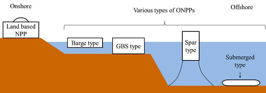
1. Introduction
2. Floating-Type ONPPs
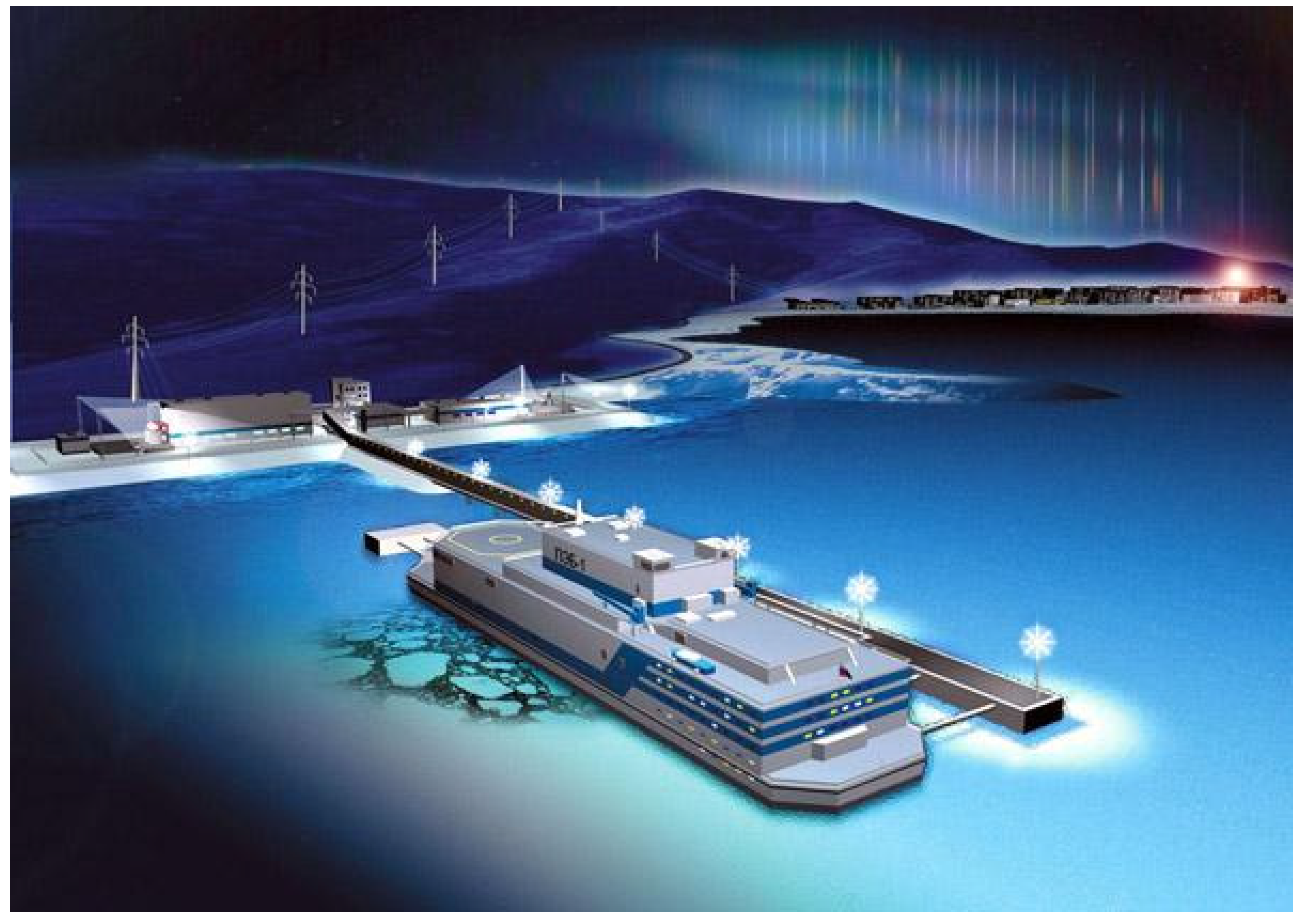
2.1. Akademik Lomonosov (Russia)

| Key parameters | Features |
|---|---|
| Electrical capacity | 35 MWe |
| Thermal capacity | 150 MWt |
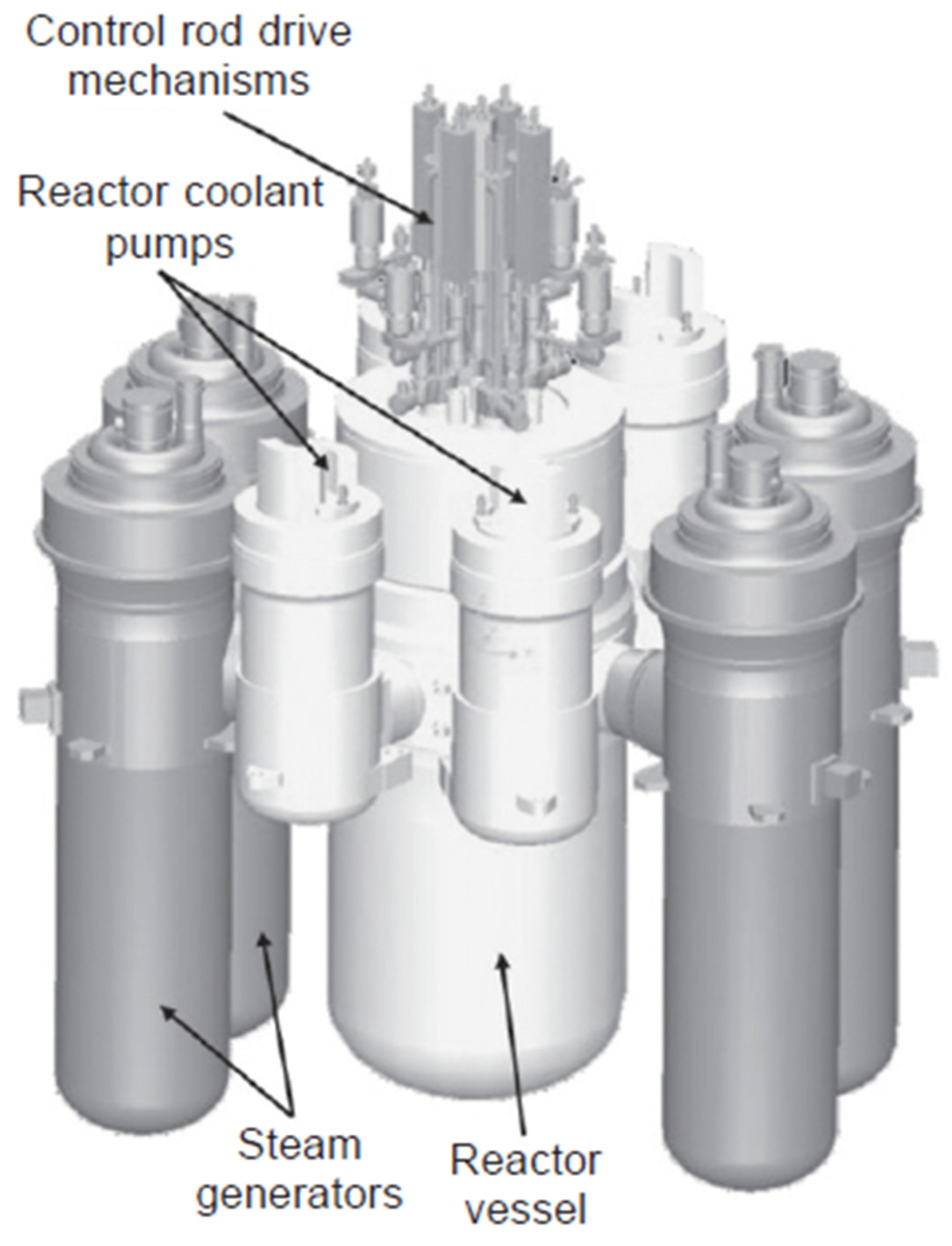
| Configuration | Compact loop |
| Primary coolant | Light water |
| Primary circulation | Forced |
- ■
- A FPU is assembled completely at a shipyard with the use of a well-developed technology for constructing atomic icebreakers and navy ships in Russia.
- ■
- After completing comprehensive tests and a customer acceptance procedure, an FPU is tugged to its mooring site where it is connected to a coastal power network to start operation.
- ■
- The plant needs onsite auxiliary facilities and lines for transmitting electricity and heat to the shore.
- ■
- The plant is mobile and can be stationed anywhere onshore and even on the beds of big rivers.
- ■
- Unsinkability of the floating unit is assured due to partition of the casing into waterproof compartments and sealing is activated after flooding of two adjacent compartments. When any two adjacent compartments of any board are flooded, maximum hydrostatic tilt is no more than 3°.
- ■
- Protection of the reactor in a collision of the floating unit with another ship is assured due to placement of the reactor in the central part of the casing under the double deck.
- ■
- The upper deck of the station has a multi-layer structure that makes it possible to damp the kinetic energy of falling air craft due to the usage of special construction units that distribute the force of an impact over a large area.
- ■
- The floating unit operates normally during storm wind with speeds up to 80 m/s.
- ■
- Seismic stability and protection from storm waves and tsunami, are assured due to use of natural or artificial barriers (islands, forelands, and wave breakers), or by placing the floating unit a safe distance from the shore.
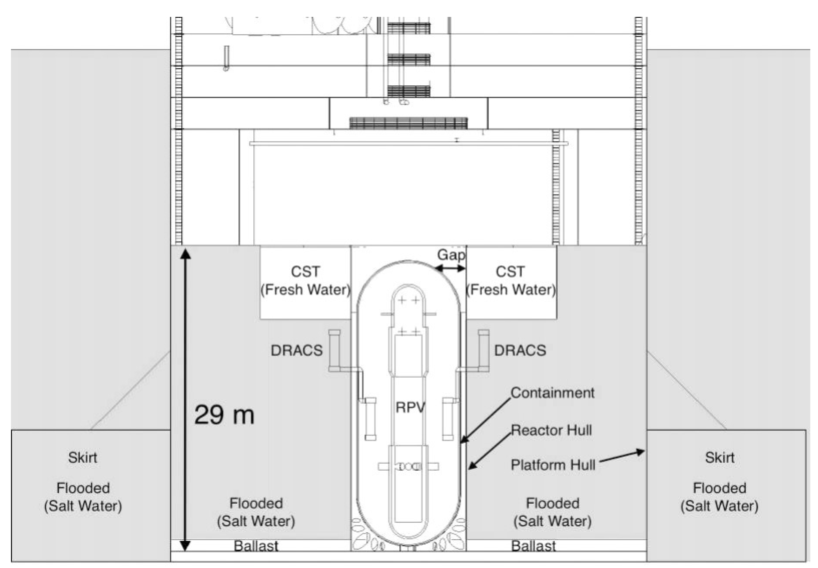
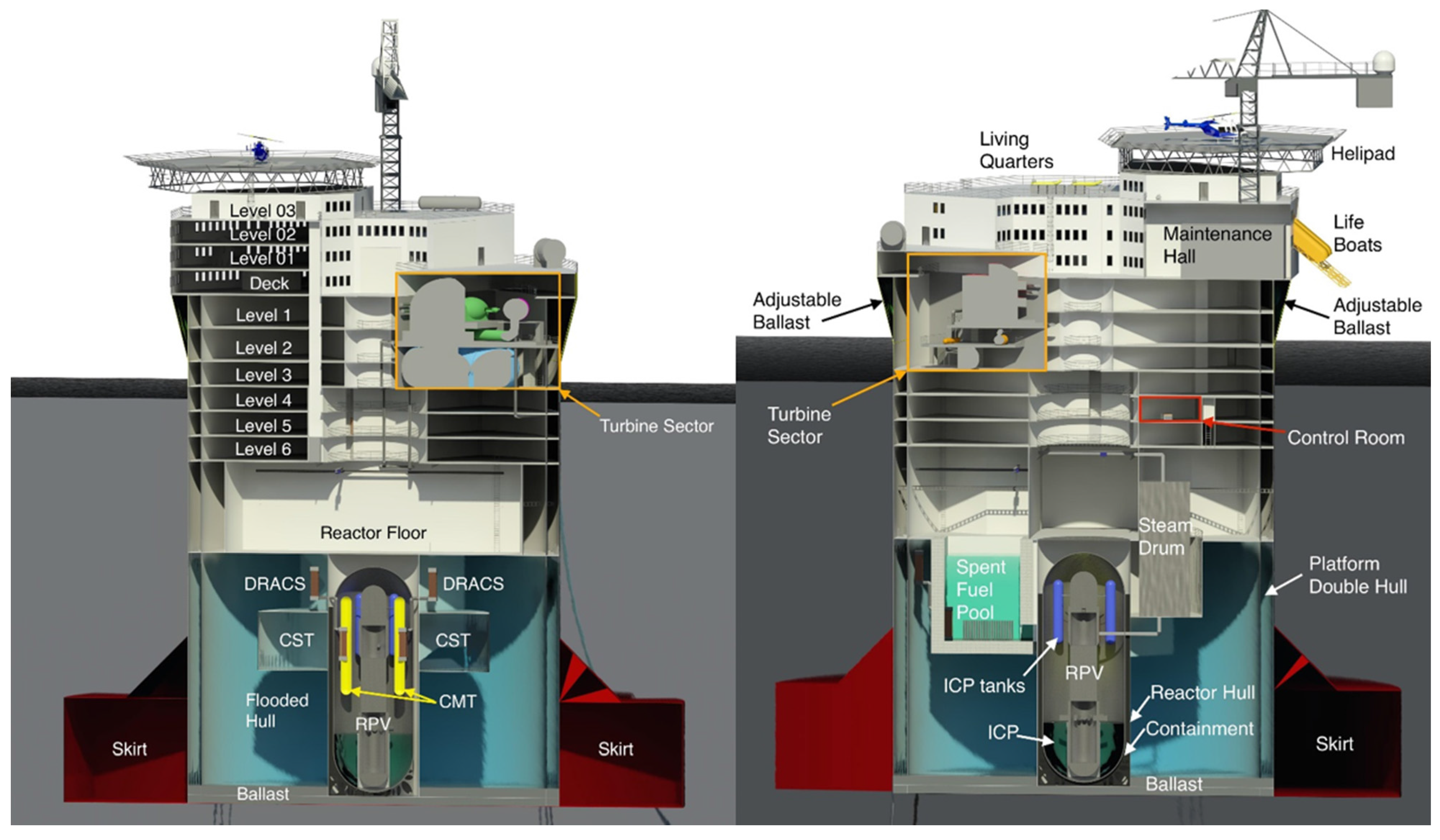
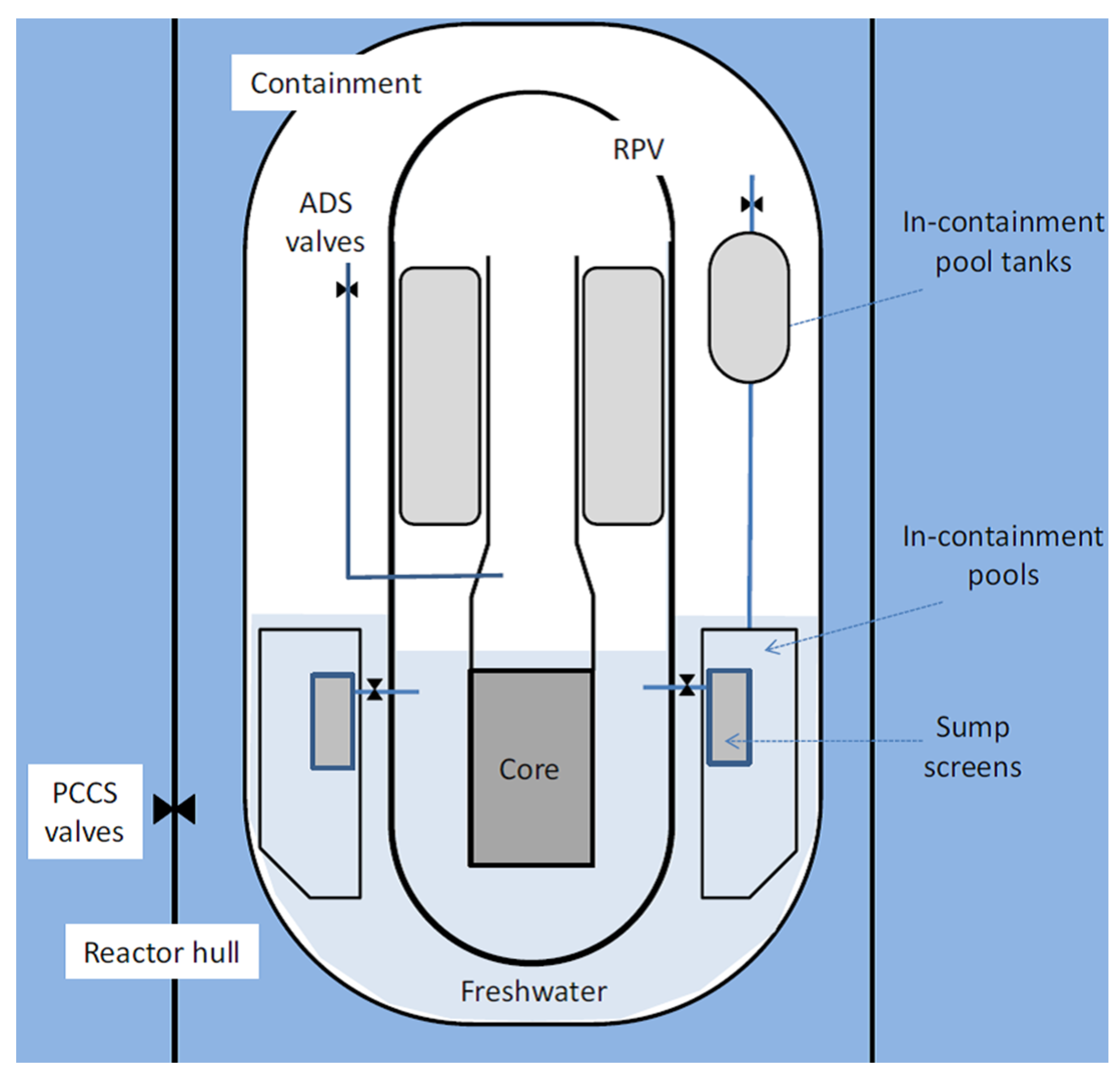
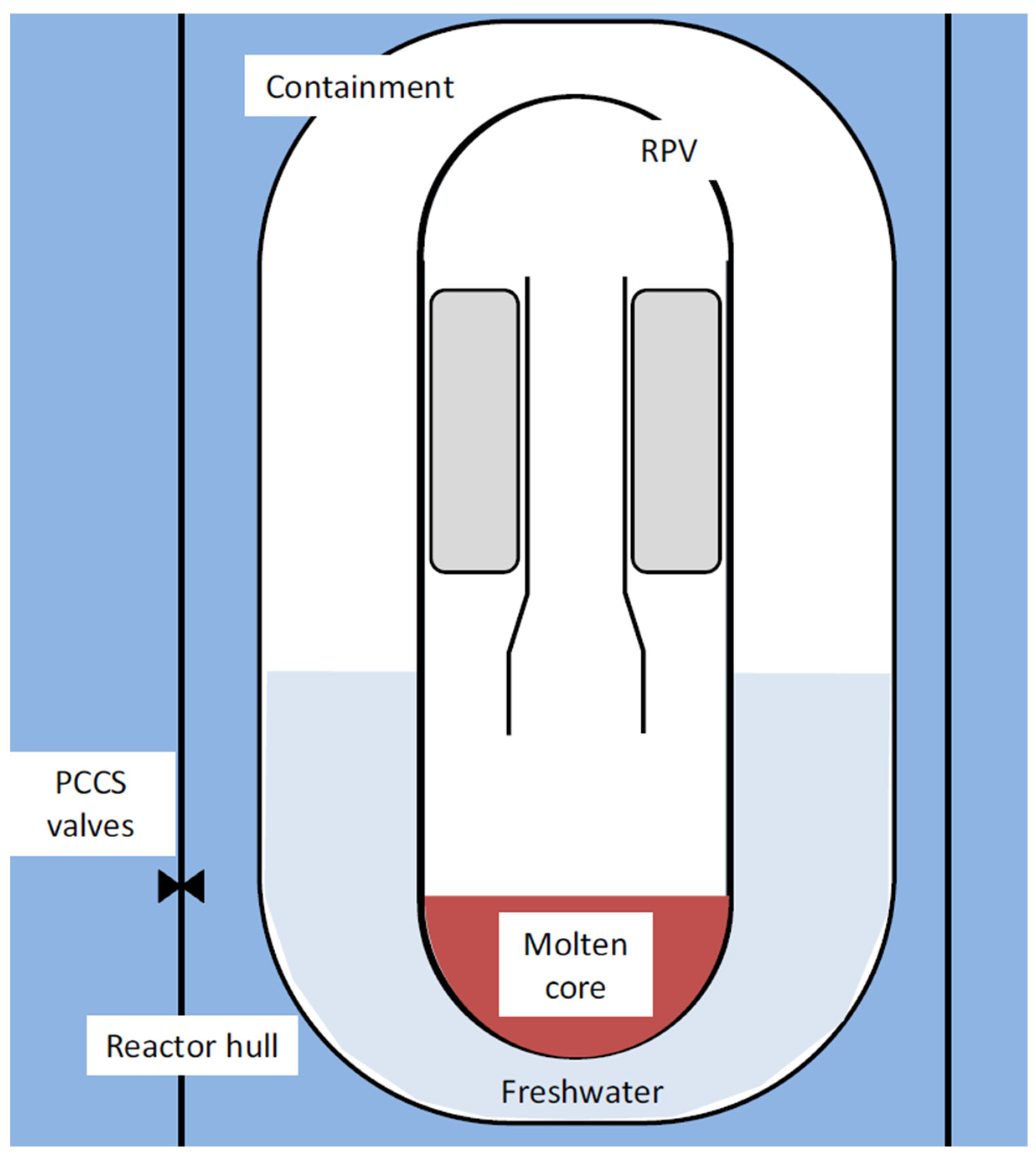
2.2. Offshore Floating Nuclear Plant (USA)
- ■
- The OFNP could have a low center of gravity for hydrodynamic and static stability, and could eliminate the transmission of seismic loads from the ocean floor, as well as loads from Tsunami, waves, and wind.
- ■
- The hydrodynamic and static stability can be tuned using an added steel skirt, seen in Figure 4.
- ■
- The spar offers the better protection to the reactor itself when compared to other offshore platform design, such as semi-submersibles or floating barges.
- ■
- The spar-type OFNP design can be constructed without all structural concrete, except radiation shielding around the spent fuel pool. Using less concrete helps to reduce cost and construction time.
- ■
- The spar enables the reactor and containment to be located at a level below the waterline, which enhances physical protection from plane crashes and collisions with ships.
- ■
- This design provides access to the ultimate heat sink: the ocean.


| Design goals | Design parameters |
|---|---|
| Platform floatation | Spar diameter, spar hull layout |
| Platform hydrostatic stability | Spar draft and diameter, heavy component layout, ballast, spar skirt dimensions |
| Adjustable draft | Skirt dimensions and ballasting system |
| Protection of critical nuclear systems from extreme natural events and terrorist attacks | Nuclear island layout, location of control room, battery room and spent fuel pool, deck elevation, bulkhead layout |
| Ease of access to ocean heat sink | Nuclear island layout, reactor hull design |
| Ease of refueling | Location of spent fuel pool and condensate storage tank |
| Freshwater production for crew and steam cycle makeup needs | Size and location of desalination units |
| Crew comfort and safety | Living quarter layout, radiological controlled area layout, location and number of lifeboats |
| Ease of construction | Spar dimensions and layout, materials chosen, overall platform geometry |
| Plant resilience to water damage and flooding | Critical electronics locations, water-tight compartment layout, condensate storage tanks location |


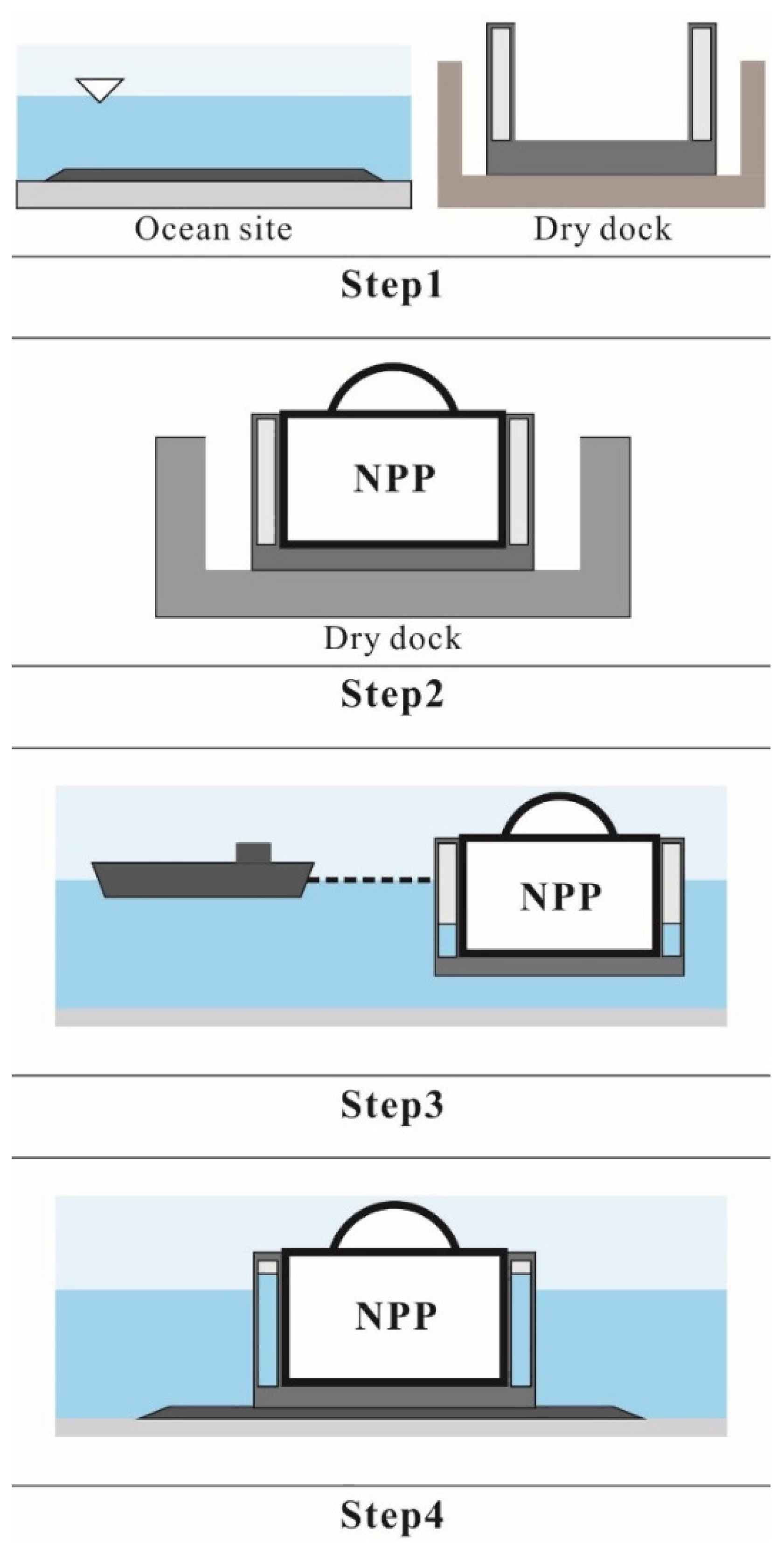
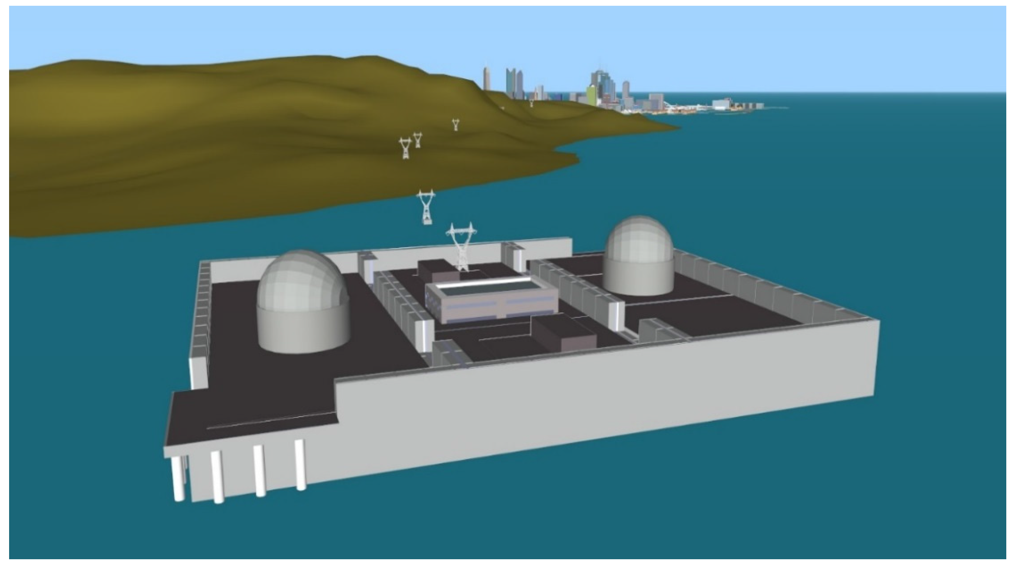
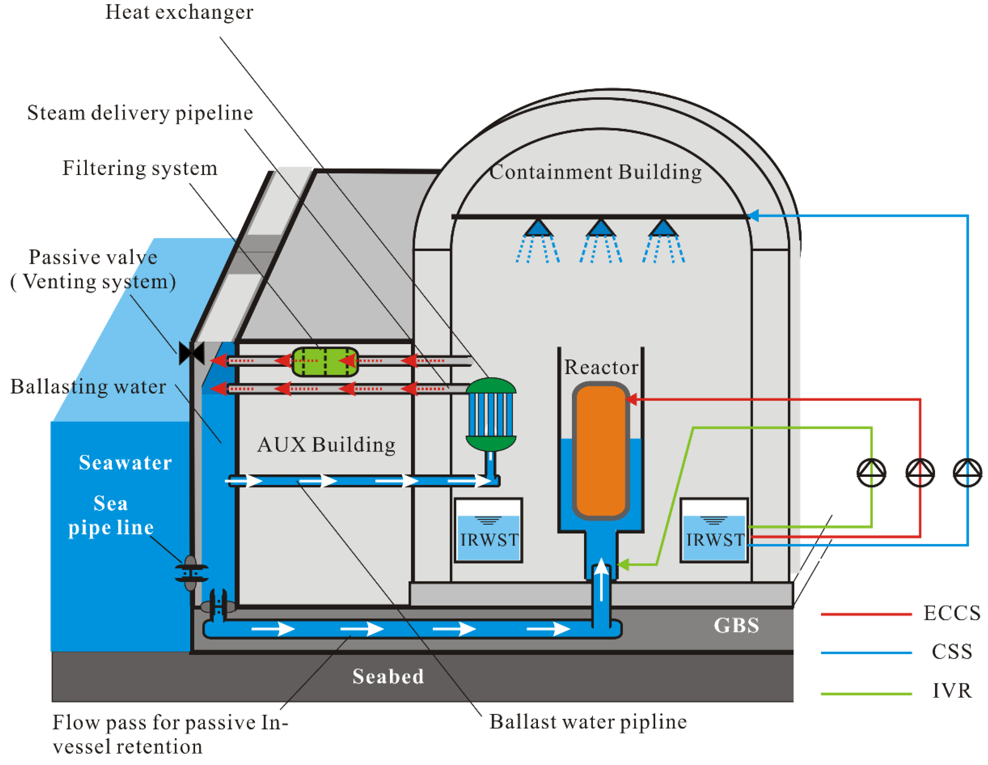
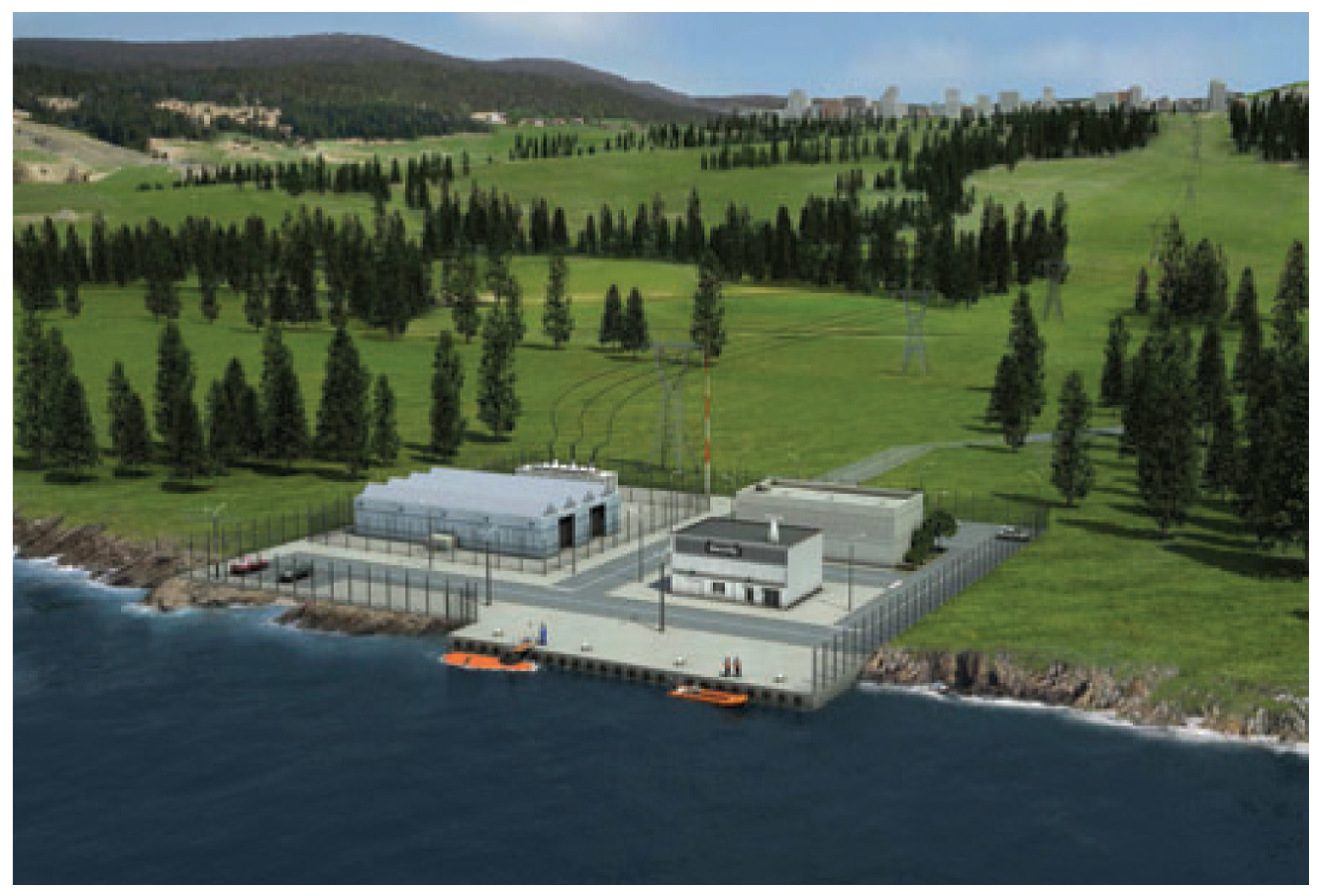
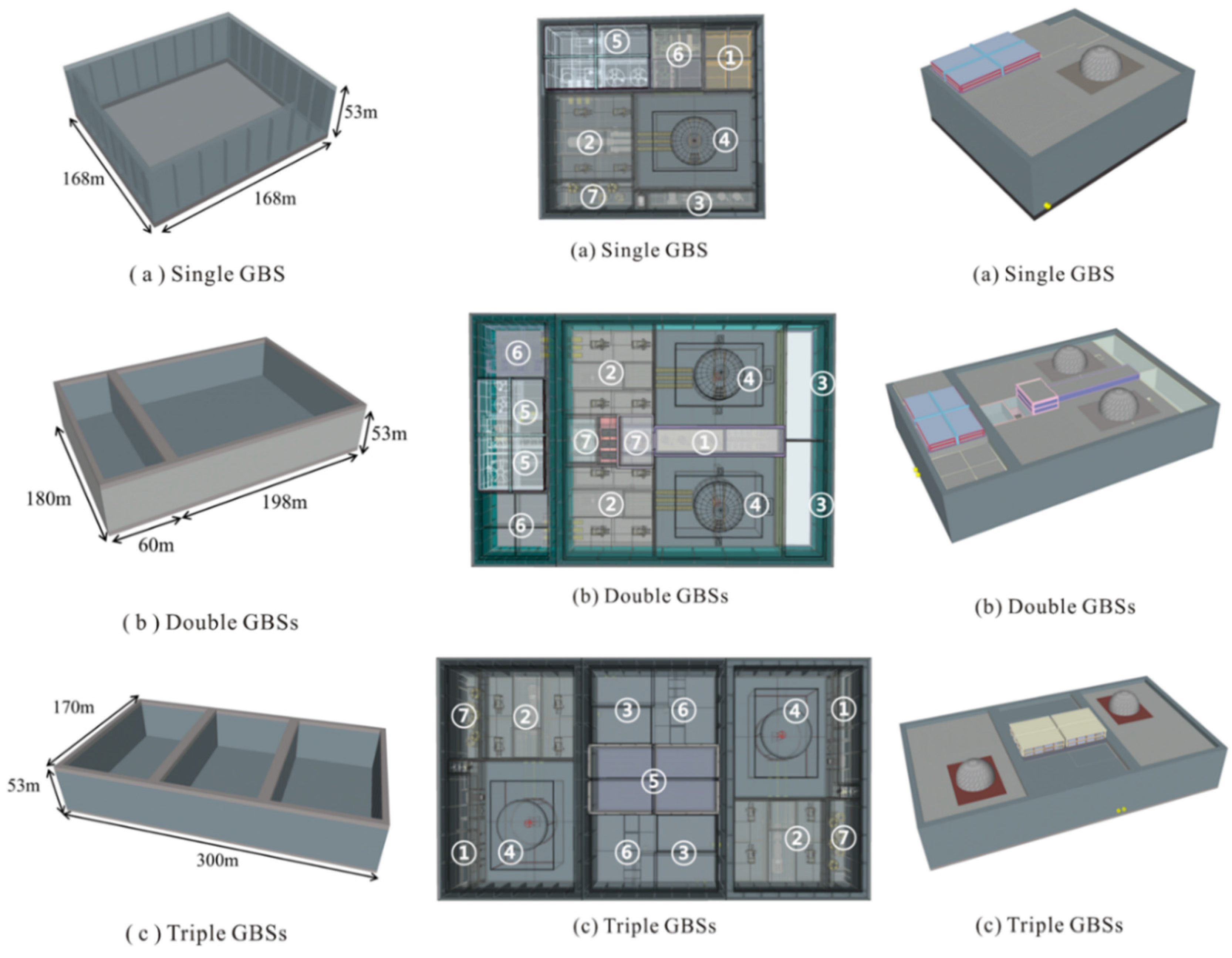
3. GBS Type ONPP
- ■
- Step 1: A GBS is constructed in a dry dock, the fabricated components of the NPP are assembled, and the installation site is prepared at the same time.
- ■
- Step 2: NPP modules (assemblages of NPP components) are mounted on the GBS. In this step, the first inspections and testing of the modularized facilities are required prior to launching.
- ■
- Step 3: The GBS-based ONPP is floated and towed to the installation site by tugboats. At the installation site, the structure is settled on the seabed using a ballasting system.
- ■
- Step 4: Nuclear fuel loading and system testing procedures are implemented after construction of the top-side facilities. Finally, the GBS-type ONPP is ready to supply electricity to land after all tests are complete.

| Requirements | Parameters | |
|---|---|---|
| Common with NPPs | Radiation protection | Nuclear/non-nuclear area |
| Safety requirements (Internal) | Core damage frequency, Containment failure frequency, Occupation radiation exposure, Turbine missile strike area | |
| Safety requirements (External) | Seismic, Tsunami, Storm, Aircraft collision | |
| Construction period and simplicity | Modularization of facilities | |
| Special for ONPP | Movable and transportable in offshore | GBS hull design, Draft limitations, Ballasting system |
| Accessibility and refueling in offshore | Ocean transportation (Ship, Helicopter, Boat) | |
| Settle on the sea floor | Seabed condition, Balanced weight distribution, Seabed foundation design | |
| Compact total general arrangement | Volume and area of the NPP buildings and facilities, Physical and functional connection between buildings | |
| Operation condition in offshore | Existing offshore facilities, Water depth, Current drift, Weather condition | |
| Safety requirements (External) | Flooding, Ship collision, Corrosion, Run up wave (Green water) | |
| External hazards protection | Reinforced concrete building, Double hull, Early warning system |

| Group | Facilities and buildings | Group | Facilities and buildings |
|---|---|---|---|
| 1 | AAC D/G building | 5 | |
| Aux. Boiler/oil storage building | |||
| Fresh water storage tank | Operator’s office | ||
| 2 | Turbine generator building | Guard house | |
| Main transformer | Accommodation | ||
| Unit Aux. Transformer | Main control building | ||
| Standby Aux. Transformer | Refuge | ||
| Excitation transformer | Fire pump & water | ||
| Spare unit Aux. Transformer | Wastewater treatment building and facilities | ||
| Other Spare transformers | |||
| 3 | Reactor make-up water tank | 6 | |
| Hold-up tank | ESW/CW Intake structure | ||
| Boric acid storage tank | Chlorination building | ||
| EDG building | CCW HX building | ||
| CO2 Storage tank | Discharge pond and facilities | ||
| Other storage tanks | |||
| 4 | Reactor building | 7 | N2 & H2 storage cylinder area |
| Aux. building | |||
| Compound building |


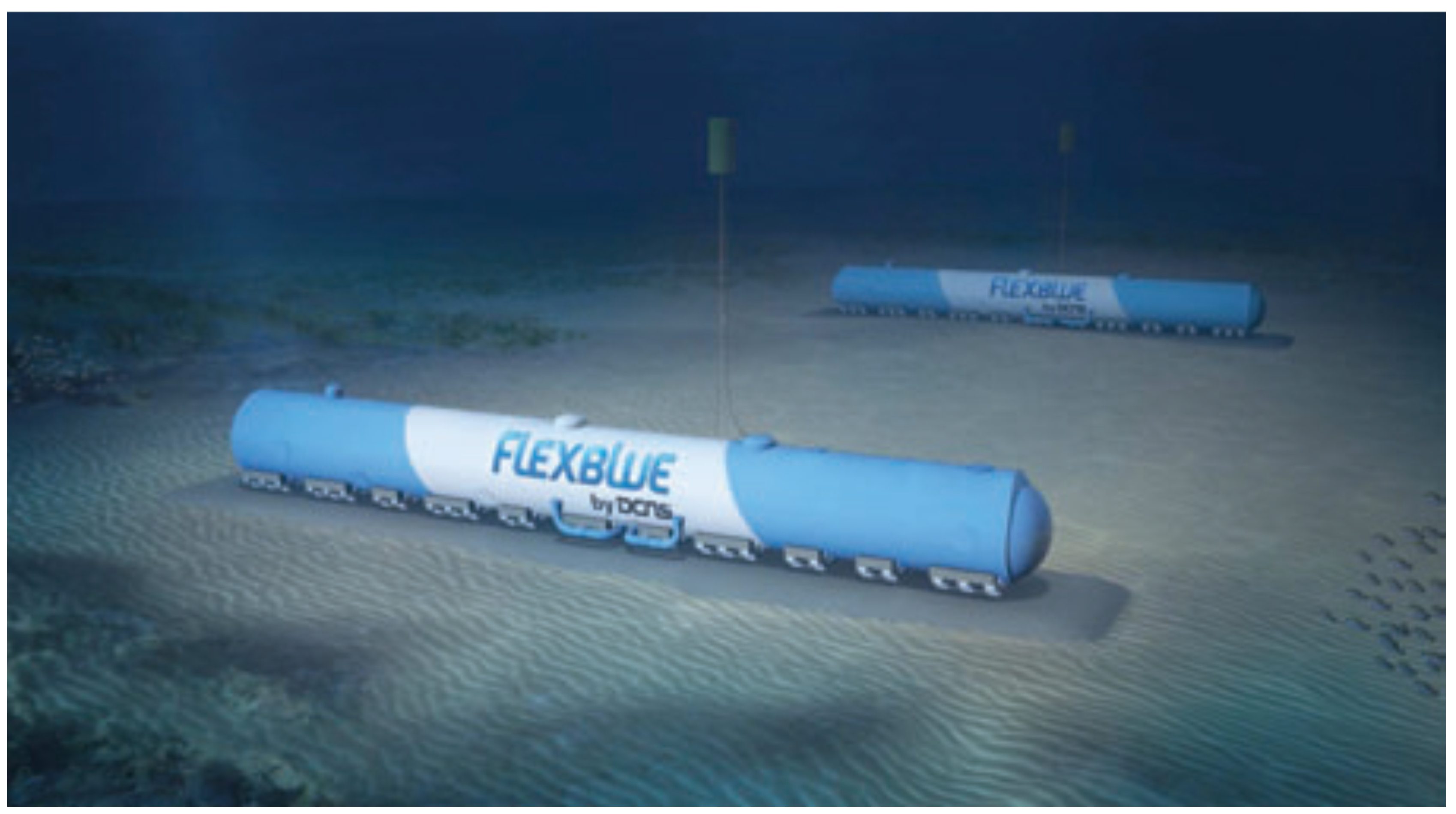
4. Submerged-Type ONPP
| Parameter | Value |
|---|---|
| Unit power rating | 160 MWe |
| Length | 146 m |
| Diameter | 14 m |
| Displacement | 16,000–20,000 ton |
| Immersion depth | Up to 100 m |
| Cycle length | 40 months |
| Lifetime | 60 years |


5. Issues and Challenges of ONPPs
- ■
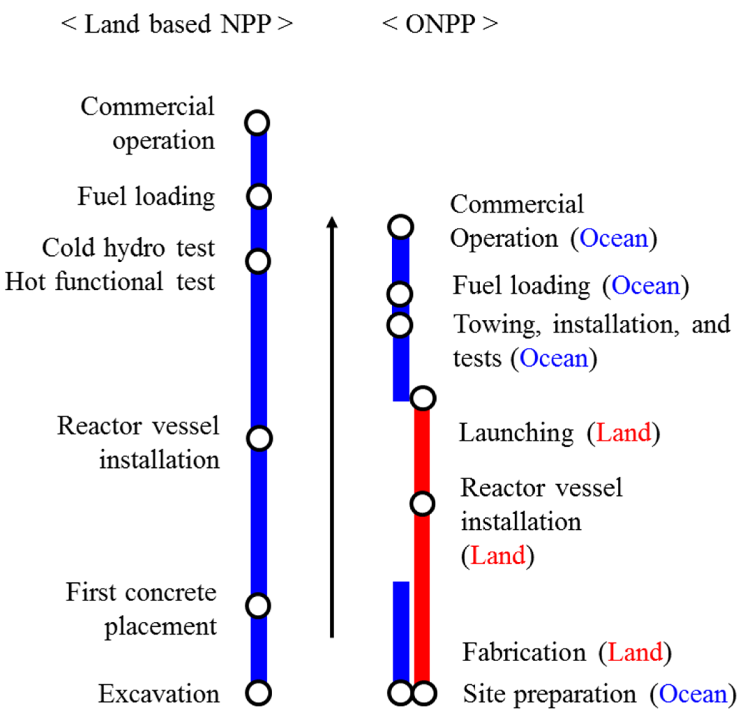
- Construction and deployment: The ocean nuclear power plants can be built in centralized facilities like ship building yards, and is transported into installation site through ocean. This valuable feature could result in higher fabrication quality and shorter construction period. Figure 18 shows that the total construction period of ONPPs is expected to be shorter than land based NPP’s because of the parallel construction procedure. That is, the fabrication of nuclear plants and the site preparation in ocean can be performed at the same time. The future expansion can be easily achieved by installing additional ONPPs adjacent to the existing facilities, without concern for acquiring additional land. Therefore, the deployment of nuclear energy systems could be accelerated.
- ■
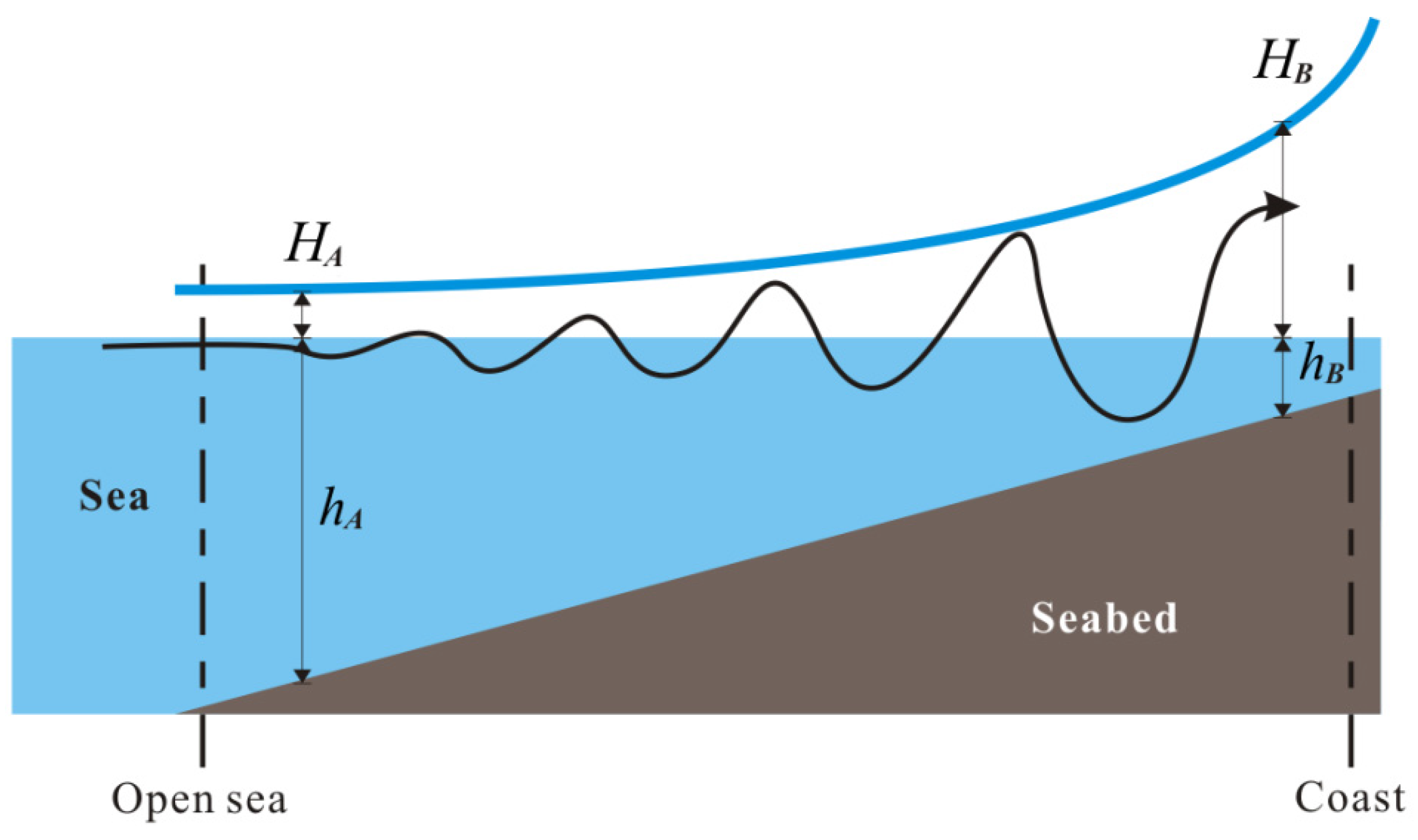
- Tsunami: One important cause of the Fukushima nuclear accident was the power outage that was caused by the post-earthquake tsunami. Therefore, the effects of tsunami should be carefully considered in the design of ONPPs. Among the three types, the target water depth of the GBS-type ONPP is relatively shallower than the others. For this reason, Lee et al. [19] investigated the effect of Tsunami on the GBS-type ONPPs using a simple wave equation.

- ■
- Marine collisions: Many types of infrastructure, both near the shoreline and offshore, could be destroyed by collisions or explosions with floating objects (e.g., hijacked oil and gas carriers). With the GBS-type ONPPs, because reinforced concrete is a durable material resistant to impact loads such as marine collisions, and given that the GBS is designed to have dual concrete walls, the design could significantly minimize damage that might be caused by a marine collision. However, with the floating-type ONPPs, marine collisions should be carefully considered because the hull structure is usually made of steel. In addition, the mooring lines should be protected from external hazards in floating-type ONPPs, whereas submerged or GBS-type ONPPs are free from the failure of mooring lines.
- ■
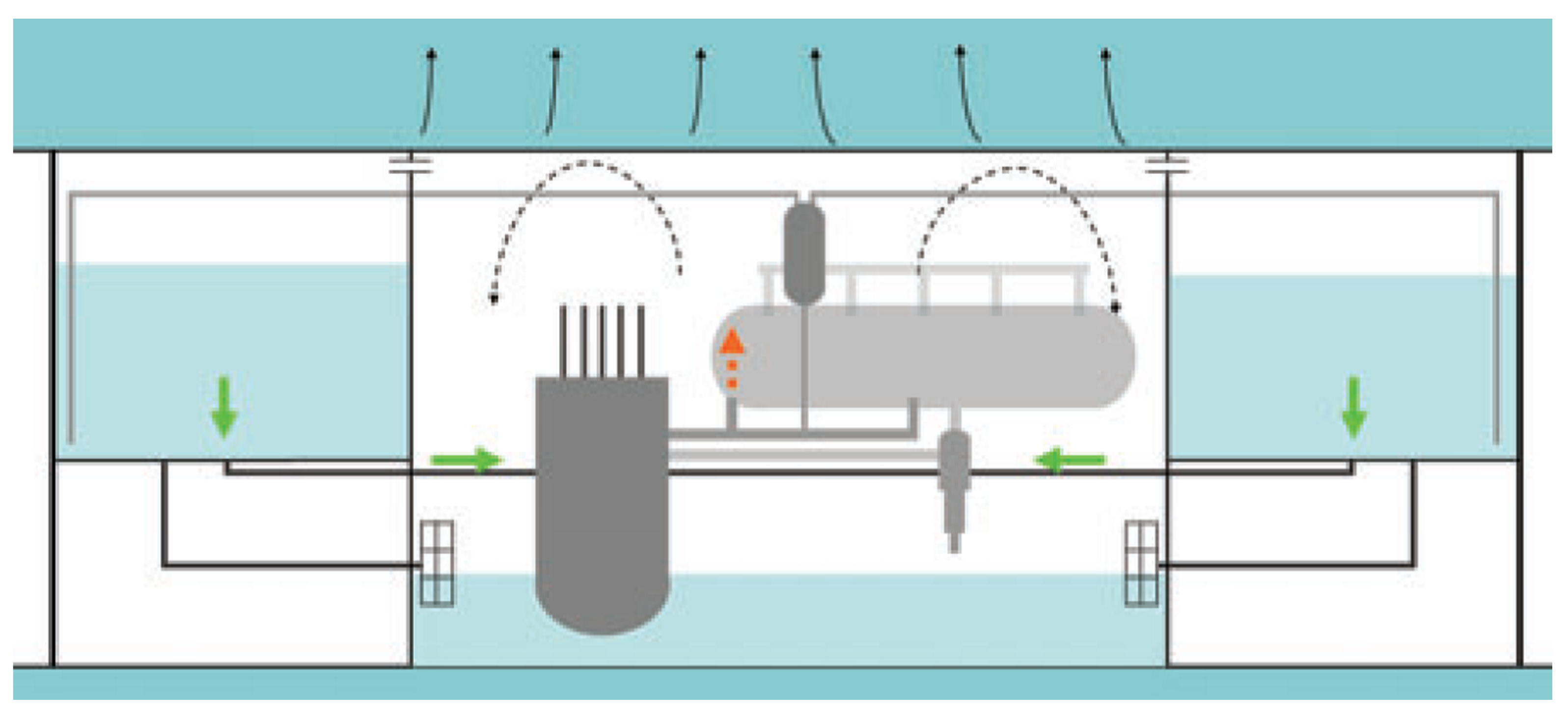
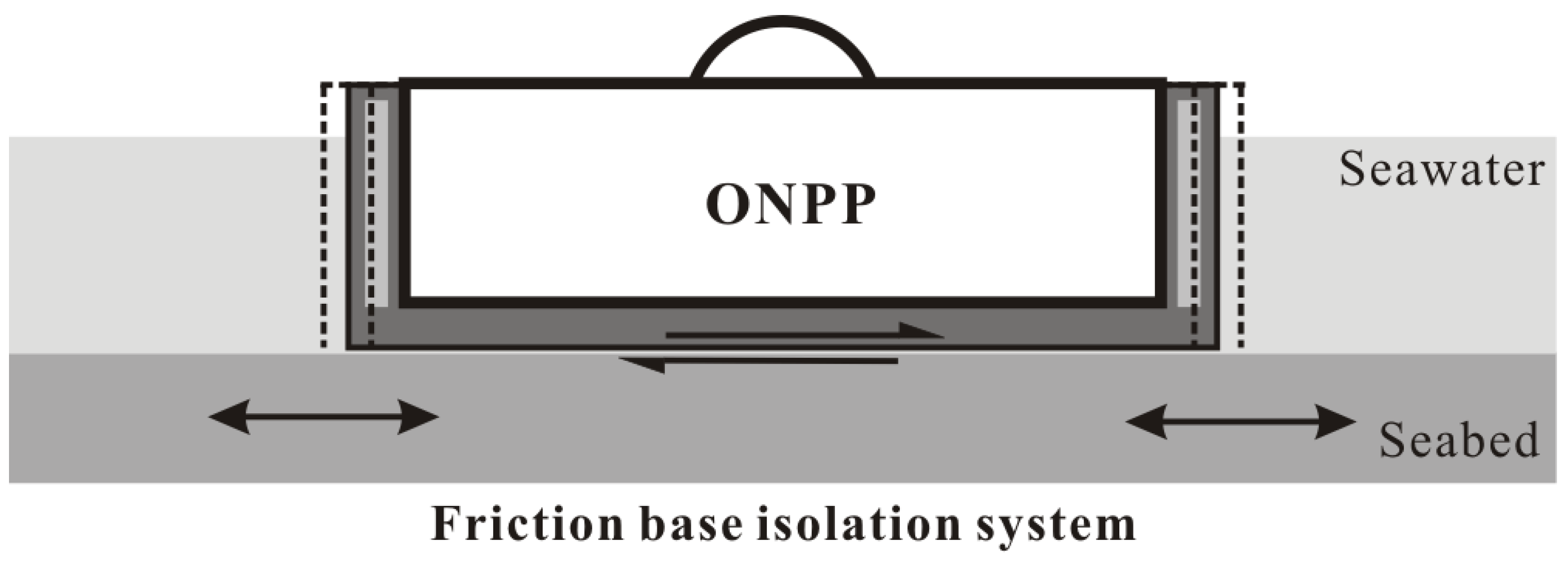
- Earthquakes: During seismic loading, the GBS-type ONPPs can be damaged because the hull is settled on the sea bottom. In GBS-type ONPPs [19,20], as shown in Figure 20, a base isolation system was introduced to reduce acceleration by adjusting the total weight of the GBS [19]. This seismic isolation technology has long been applied to land-based NPPs and to other plants. Further details were described in [20]. The motions of submerged-type ONPPs should also carefully be analyzed for reaction to seismic loading because the cylindrical structure is anchored slightly above the sea bottom. Even so, earthquakes are not a principle consideration for floating-type ONPPs.
- ■
- Physical protection: Since ONPPs are located away from land, physical protection from external threats (e.g., direct attack, armed intrusion, hijacked vessels/aircraft, and sabotage) can be a challenging issue as for many offshore oil and gas platforms. Especially, underwater attack is a unique treat compared to land based NPPs, and delayed time to take security measure from land should be carefully considered. Thus, improved physical protection systems (e.g., robust hull design, additional hull protection system, and an early warning system) and measures are required to secure ONPPs compared to the land based NPPs.
- ■
- Reliability and maintenance: High plant availability plays an important role in economic competitiveness of ONPPs. High reliability can be achieved with design simplification, provision of enough operating margin, and planning extensive periodic maintenance. Since the number of operating personnel is limited in ONPPs, most of the works at ONPP site should have better plan and rely more on automated systems. Also, reducing operation and maintenance cost is an important issue for ONPPs. Table 6 shows the design recommendation for maximum acceleration of floating structures from international maritime organization (IMO). In contrast to a land-based nuclear power plant, which is designed to mainly withstand seismic acceleration (e.g., APR1400 for 0.3 g, Westinghouse SMR for 0.25 g), floating type ONPPs have to be designed to satisfy higher acceleration standard under Safety Class (SC)-1 and Plant Process Condition (PPC)-3 limit. This higher design basis acceleration will result in escalated structural integrity and acceleration isolation system for reactor safety system and emergency reactor shutdown system design. Thus, more improved structural design are necessary when applying current land-based nuclear reactors to ONPP. This will inevitably increase the capital cost. Therefore, in order to have advantages in economic effectiveness, decrease of operation and maintenance cost will be one of the key issues.
| Pitch | Yaw | Roll | |
|---|---|---|---|
| PPC-4 | 1.0 g | 1.0 g | 0.5 g |
| SC-1, PPC-3 | 0.7 g | 0.8 g | 0.4 g |
| SC-2,3 | 0.6 g | 0.7 g | 0.35 g |
| SC-4 | 0.5 g | 0.6 g | 0.3 g |
| PPC-1,2 | - | - | - |
- ■
- Human errors: The ONPP should be designed to minimize potential human errors and the level of human actions needed for maintenance and operation. This is necessary to reduce the operation and maintenance cost. Since the working environment of ONPPs will be more stressful for human, and human resource will be more limited than land based NPPs, it is more likely that ONPP operators can make mistakes. Thus, the design should reduce the number of actions required by design simplification and automation. Automated equipment that could be remotely operated should be able to perform availability tests of safety-related systems.
- ■
- Others: In addition to several external hazards in ocean, there are many difficulties which should be taken into account in the design of ONPPs. Storm wind and the severe wave loads should be considered in the design of floating-type ONPPs even though they are intended to be tightly moored. The phenomenon known as a turbidity current, which results from an underwater land slide, could cause damage to underwater technology. Also, water proof compartments, corrosion, and maintenance could be the most important features affecting the life span and structural reliability of an ONPP. This is more important in design of submerged-type ONPPs because these are harder to access and repair in relatively deep water. Last, the emergency evacuation scenario and procedures should be well designed and well organized.
6. Conclusions
Acknowledgments
Author Contributions
Conflicts of Interest
References
- Hirose, K. 2011 Fukushima Dai-ichi nuclear power plant accident: Summary of regional radioactive deposition monitoring results. J. Environ. Radioact. 2012, 111, 13–17. [Google Scholar] [CrossRef] [PubMed]
- Chu, S.; Arun, M. Opportunities and challenges for a sustainable energy future. Nature 2012, 488, 294–303. [Google Scholar] [CrossRef] [PubMed]
- Shropshire, D.; Purvins, A.; Papaioannou, I.; Maschio, I. Benefits and cost implications from integrating small flexible nuclear reactors with off-shore wind farms in a virtual power plant. Energy Policy 2012, 46, 558–573. [Google Scholar] [CrossRef]
- Kuznetsov, V. Options for small and medium sized reactors (SMRs) to overcome loss of economies of scale and incorporate increased proliferation resistance and energy security. Prog. Nuclear Energy 2008, 50, 242–250. [Google Scholar] [CrossRef]
- Rowinskia, M.K.; Whitea, T.J.; Zhao, J. Small and medium sized reactors (SMR): A review of technology. Renew. Sustain. Energy Rev. 2015, 44, 643–656. [Google Scholar] [CrossRef]
- Vujic, J.; Bergmann, R.M.; Skoda, R.; Miletic, M. Small modular reactors: Simpler, safer, cheaper? Energy 2012, 45, 288–295. [Google Scholar] [CrossRef]
- Ingersoll, D.T. Handbook of Small Modular Nuclear Reactors; Elsevier Ltd.: Cambridge, UK, 2015; pp. 27–60. [Google Scholar]
- Hirdaris, S.E.; Cheng, Y.F.; Shallcross, P.; Bonafoux, J.; Carlson, D.; Prince, B.; Sarris, G.A. Considerations on the potential use of Nuclear Small Modular Reactor (SMR) technology for merchant marine propulsion. Ocean Eng. 2014, 79, 101–130. [Google Scholar] [CrossRef]
- Zav’yalov, S.N.; Sozonyuk, V.A. Marketing studies, possibilities for commercialized floating nuclear heat and power plants on the internal and external markets. In Abstract of Reports at an Interdepartmental Science and Application Conference on Floating NHPP – Validation of Safety and Cost-Effectiveness, Prospects for Use in Russia and Abroad, Nizhnii Novgorod, Russia, 25–26 November 2008; pp. 3–10.
- International Atomic Energy Agency. Status Report for Advanced Nuclear Reactor Designs; International Atomic Energy Agency: Vienna, Austria, 2011; Report 73. [Google Scholar]
- Lepekhin, A.; Andreeva-Andrievskaya, L.; Kuznetsov, V. Status of Russian small and medium sized reactor activities. In Proceedings of the Meeting of the International Framework for Nuclear Energy Cooperation, Rome, Italy, 6 December 2010.
- Fadeev, Y. KLT-40S reactor plant for the floating CNPP FPU. In Proceedings of the IAEA Interregional Workshop on Advanced Nuclear Reactor Technology for Near-Term Deployment, Vienna, Austria, 4–8 July 2011.
- Buongiorno, J.; Jurewicz, J.; Golay, M.; Todreas, N. The offshore floating nuclear plant (OFNP) concept. Nuclear Technol. 2015, in press. [Google Scholar]
- Jurewicz, J.; Buongiorno, J.; Golay, M.; Todreas, N. Spar-type platform design for the offshore floating nuclear power plant. In Proceeding of the 10th International Topical Meeting on Nuclear Thermal Hydraulics, Operation and Safety (NUTHOS-10), Okinawa, Japan, 14–18 December 2014.
- Kolmayer, A. Blue submarine: The Flexblue® offshore nuclear reactor. Power Eng. Int. 2011, 19, 126–131. [Google Scholar]
- Haratyk, G.; Lecomte, C.; Briffod, F. Flexblue®: A subsea and transportable small modular power plant. In Proceedings of the International Congress on Advances in Nuclear Power Plants 2014, Charlotte, NC, USA, 6–9 April 2014.
- Haratyk, G.; Ingremeau, J.; Gourmel, V. CFD investigation of Flexblue® hull. In Proceedings of the Nuclear Thermal Hydraulics, Operation and Safety-10, Okinawa, Japan, 14–18 December 2014.
- Gerwick, B.C., Jr. Construction of Marine and Offshore Structures; CRC Press: London, UK, 2007. [Google Scholar]
- Lee, K.; Lee, K.H.; Lee, J.I.; Jeong, Y.H.; Lee, P.S. A new design for offshore nuclear power plants with enhanced safety features. Nuclear Eng. Des. 2013, 254, 129–141. [Google Scholar] [CrossRef]
- Kim, M.G.; Lee, K.H.; Kim, S.G.; Woo, I.G.; Han, J.H.; Lee, P.S.; Lee, J.I. Conceptual studies of construction and safety enhancement of ocean SMART mounted on GBS. Nuclear Eng. Des. 2014, 278, 558–572. [Google Scholar] [CrossRef]
- Bae, K.H.; Kim, H.C.; Chang, M.H.; Sim, S.K. Safety evaluation of the inherent and passive safety features of the smart design. Ann. Nuclear Energy 2001, 28, 333–349. [Google Scholar] [CrossRef]
- Chung, Y.J. SMART safety system. In Proceedings of the Transactions of the Korean Nuclear Society Spring Meeting, Jeju, Korea, 16–18 May 2012.
- Kim, I.; Kim, D.S. APR1400: Evolutionary korean next generation reactor. In Proceedings of the 10th International Conference on Nuclear Engineering, American Society of Mechanical Engineers, Arlington, VA, USA, 14–18 April 2002; pp. 845–851.
- Lapp, C.W.; Golay, M.W. Modular design and construction techniques for nuclear power plants. Nuclear Eng. Des. 1997, 172, 327–349. [Google Scholar] [CrossRef]
- Conant, E. Russia’s new empire: Nuclear power. Sci. Am. 2013, 309, 88–93. [Google Scholar] [CrossRef] [PubMed]
- Andreeva-Andrievskaya, L.N.; Kuznetsov, V.P. Transportable nuclear power facilities in the INPRO international project. Atomic Energy 2012, 111, 340–343. [Google Scholar] [CrossRef]
- Khlopkin, N.S.; Pologikh, B.G.; Makarov, V.I.; Lystsov, V.N. Infrastructure of low-capacity nuclear power plants. Atomic Energy 2012, 111, 336–339. [Google Scholar] [CrossRef]
- Balunov, B.F.; Shcheglov, A.A.; Il’in, V.A.; Saikova, E.N.; Bol’shukhin, M.A.; Bykh, O.A.; Sokolov, A.N. An experimental substantiation of the emergency cool-down system project for the KLT-40S reactor installation of a floating nuclear cogeneration station. Therm. Eng. 2011, 58, 418–423. [Google Scholar] [CrossRef]
- Kostin, V.I.; Panov, Y.K.; Polunichev, V.I.; Shamanin, I.E. Floating power-generating unit with a KLT-40S reactor system for desalinating sea water. Atomic Energy 2007, 102, 31–35. [Google Scholar] [CrossRef]
- Zhang, F.; Yang, J.; Li, R. A Review on the technical development of spar platform. China Offshore Platf. 2005, 2, 6–11. [Google Scholar]
- Chang, S.H.; Kim, S.H.; Choi, J.Y. Design of integrated passive safety system (IPSS) for ultimate passive safety of nuclear power plants. Nuclear Eng. Des. 2013, 260, 104–120. [Google Scholar] [CrossRef]
- International Maritime Organization. Code of Safety for Nuclear Merchant Ship; International Maritime Organization: London, UK, 1981. [Google Scholar]
© 2015 by the authors; licensee MDPI, Basel, Switzerland. This article is an open access article distributed under the terms and conditions of the Creative Commons Attribution license (http://creativecommons.org/licenses/by/4.0/).
Share and Cite
Lee, K.-H.; Kim, M.-G.; Lee, J.I.; Lee, P.-S. Recent Advances in Ocean Nuclear Power Plants. Energies 2015, 8, 11470-11492. https://doi.org/10.3390/en81011470
Lee K-H, Kim M-G, Lee JI, Lee P-S. Recent Advances in Ocean Nuclear Power Plants. Energies. 2015; 8(10):11470-11492. https://doi.org/10.3390/en81011470
Chicago/Turabian StyleLee, Kang-Heon, Min-Gil Kim, Jeong Ik Lee, and Phill-Seung Lee. 2015. "Recent Advances in Ocean Nuclear Power Plants" Energies 8, no. 10: 11470-11492. https://doi.org/10.3390/en81011470
APA StyleLee, K.-H., Kim, M.-G., Lee, J. I., & Lee, P.-S. (2015). Recent Advances in Ocean Nuclear Power Plants. Energies, 8(10), 11470-11492. https://doi.org/10.3390/en81011470