A Semantic Middleware Architecture Focused on Data and Heterogeneity Management within the Smart Grid


Abstract
:
1. Introduction
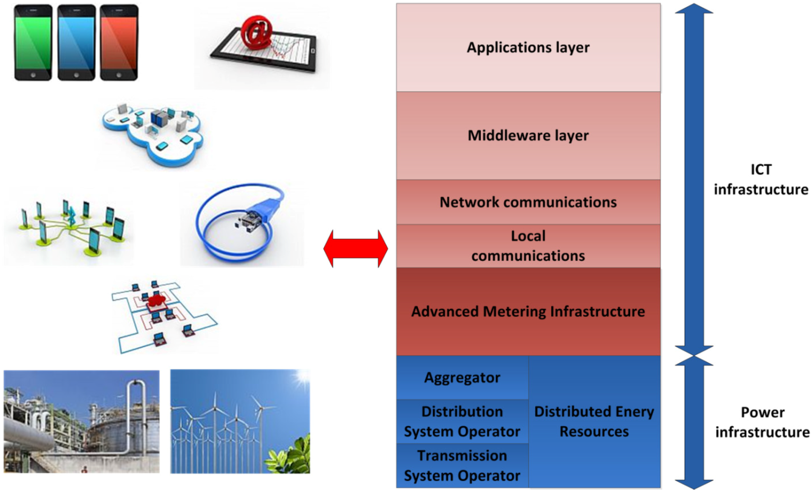
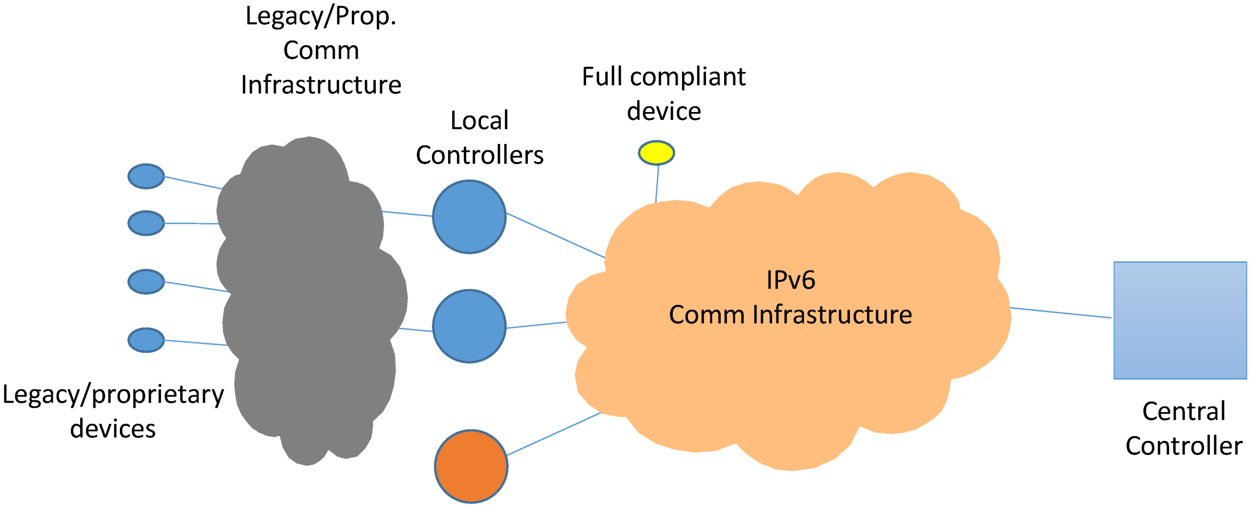
- Transmission System Operator (TSO): it is the provider of the conventional grid equipment, which is responsible for power transmission, especially when high voltage electricity is transferred;
- Distribution System Operator (DSO): it is the entity that manages medium voltage transmission. Also, it usually behaves as the mediating actor between the TSO and the aggregator, selling the energy to the latter;
- Aggregator: this company purchases the electricity that is sold by the DSO, and resells it to the end users that are going to consume it. However, they may be able to collect a share of energy by themselves;
- “Prosumer”: while traditional energy consumers are present in the Smart Grid as well, they are also able to obtain energy from their own equipment (solar panels, small-sized windmills, etc.), thus becoming an actor able to produce and consume energy, hence the term “prosumer” (producer + consumer).
- Distributed Energy Resources (DERs): they have been previously referred to as the equipment that a prosumer employs in order to obtain energy from its local environment. Commonly, these resources will be located at the user workplace or dwelling;
- Advanced Metering Infrastructure (AMI): it is the equipment used for energy-related measurements (consumption, costs, etc.); it is usually placed at the end user’s surroundings;
- Big Data: rather than being a hardware-based technology, Big Data is about the management and analysis of the significant amount of information that will be required within the Smart Grid, which will be advisable if services and applications are to be implemented satisfactory.

- Smart Grid focus guarantees that an optimized solution has been developed for the specific needs and services of this environment, such as Demand Side Management, Demand Response or energy consumption forecasting. Should an ICT-based architecture be ported from any other environment to the Smart grid, major changes are likely to be required, thus resulting in a more constrained system and additional adaptation efforts;
- A prominent information management layer is a must-have if information is going to be transferred with efficiency, for it can be charged with the tasks typically related with data (request/response transfers, context awareness, entity registration, etc.). Alas, semantic capabilities are more easily added if they become located in a layer or component as this;
- Semantic capabilities are a compelling addition to a Smart Grid-based architecture because they allow the system to have smarter capabilities: registration can offer more information about the entities involved, applications are able to implement more complex functionalities and the information semantics allows the system to learn new concepts that will improve the future performance of the system.
- A semantic middleware architecture has been implemented from scratch for a microgrid encased in a Smart Grid. It does not only abstract hardware heterogeneity for the upper layers, but also has semantic features implemented which are capable of dealing with transmitted information according to its meaning (semantic storage of information, SPAQRL requests, etc.). Also, while tests have been done using a microgrid model, it could be installed in several of them that altogether make a Smart Grid, provided that there is a coordination mechanism among the different microgrids (for example, multi-agent coordination for global information discovery [18]);
- This semantic middleware architecture has been developed using open software tools. Fuse ESB and Java programming language have been critical for the architecture implementation. In this way, the architecture can be modified by third party developers and further expanded, and its services can be learnt and utilized for research purposes;
- The semantic middleware architecture presented here is distributed. It can be deployed in most of the devices that would be expected in a microgrid so as to have them cooperating simultaneously in different parts of the system. AMI open enough to have Fuse ESB-like components can have software bundles installed, as shown in section 5.
2. Related Works

| Smart grid focus | Grade description |
|---|---|
| Grade: 5 | Information management platform conceived, designed and implemented for the Smart Grid from the beginning. Tests are provided by using a number of actual devices. Extensive information about its features is provided. |
| Grade: 4 | Information management platform conceived, designed and implemented for the Smart Grid almost from scratch. Tests are provided by using simulation tools rather than actual devices. |
| Grade: 3 | The information management platform has used a significant plethora of components prior to its usage in the Smart Grid, although the development has been tested and modified for the latter scenario. |
| Grade: 2 | Information management platform ported from another kind of system alien to the Smart Grid. Important information is missing. |
| Grade: 1 | The information management platform is not related with the Smart Grid / very scarce information is provided about its characteristics. |
| Information management prominence | Grade description |
|---|---|
| Grade: 5 | Specific components designed and implemented in order to treat and enrich the data that is transferred throughout the system. Extensive information is provided about specific characteristics of the Smart Grid. |
| Grade: 4 | A detailed description about information management is provided, without having specific or prominent components used for them. Information is provided about specific characteristics of the Smart Grid |
| Grade: 3 | Data regarding information management is offered at an acceptable level: overall characteristics of the system (block diagrams, etc.) are provided, but there are less data about information treatment and transfer. |
| Grade: 2 | Provided data is a superficial description of the characteristics of information management without profound, detailed description. |
| Grade: 1 | No data available about management procedures or very scarce information is provided about its characteristics. |
| Semantic capabilities | Grade description |
|---|---|
| Grade: 5 | Semantic capabilities have been made part as part of the proposal since the first design stages and are used extensively as part of the proposal. Descriptions regarding used ontologies or ontology languages provided. |
| Grade: 4 | Semantic capabilities are added for prominent services. The amount of functionalities using them is significant. Detailed information provided about their characteristics and usage. |
| Grade: 3 | Semantics are used for a small set of functionalities. Information regarding semantics is offered at an intermediate level (theoretical concepts, description of the ontology). |
| Grade: 2 | Information regarding semantics is treated at a superficial level (theoretical concepts). Few information is provided about semantic capabilities |
| Grade: 1 | No semantic capabilities are provided in the proposal / very scarce information is provided about its characteristics. |
2.1. A Cloud Optimization Perspective
2.2. Stochastic Information Management in Smart Grid
2.3. Smart-Frame
2.4. Semantic Information Modeling for Emerging Applications
2.5. KT’s Smart Grid Architecture and Open Platform
2.6. Service-Oriented Middleware for the Smart Grid
2.7. Advanced Demand Side Management for the Future Smart Grid
2.8. Information Framework of Smart Distribution Grid
3. An Evaluation on Information Management Platforms for the Smart Grid
- Our proposal has been specifically conceived for a microgrid encased in a Smart Grid from the beginning. Instead of adapting an existing solution, which in fact could end up with a poor port of an earlier development, conceiving a new information management platform with proven software solutions seemed as a better starting ground;
- It is emphasized how information is managed by means of specific tools. A middleware architecture was the software layer that best could solve issues with hardware and information heterogeneity, rather than trying ad hoc solutions that should be changed for different devices;
- Semantics and smarter data treatment are enabled. As part of the current efforts done in software engineering, information is enriched by using ontologies and semantic features to offer services under a Service-oriented Architecture (SOA) paradigm.
| Proposal regular name | Smart grid focus | Information management prominence | Semantic capabilities | Total/15 (pts.) |
|---|---|---|---|---|
| A cloud optimization perspective | 4 | 4 | 1 | 9/15 |
| Stochastic information management in smart grid | 4 | 2 | 1 | 7/15 |
| Smart-frame | 4 | 3 | 1 | 8/15 |
| Semantic information modeling for emerging applications | 3 | 2 | 4 | 9/15 |
| KT’s smart grid architecture | 5 | 3 | 1 | 9/15 |
| Service-oriented middleware for the smart grid | 4 | 5 | 1 | 10/15 |
| Advanced demand side management for the future smart grid | 3 | 2 | 1 | 6/15 |
| Information framework of smart distribution grid | 2 | 1 | 1 | 4/15 |
4. Description of the Proposal


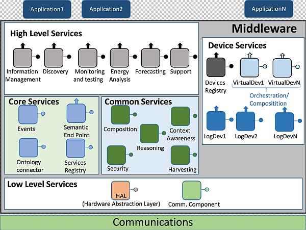
4.1. Architecture Presentation
- It required both SOA concepts to be used and a layered model for services divided and located in upper and lower levels;
- It should be a distributed middleware architecture, where different hardware components may have several middleware parts deployed;
- Semantic characteristics should be included. This was a critical challenge, for a particular ontology that would have the middleware architecture as its domain would be employed for semantic service and data registration, in order to infer knowledge from the information that is being transferred.

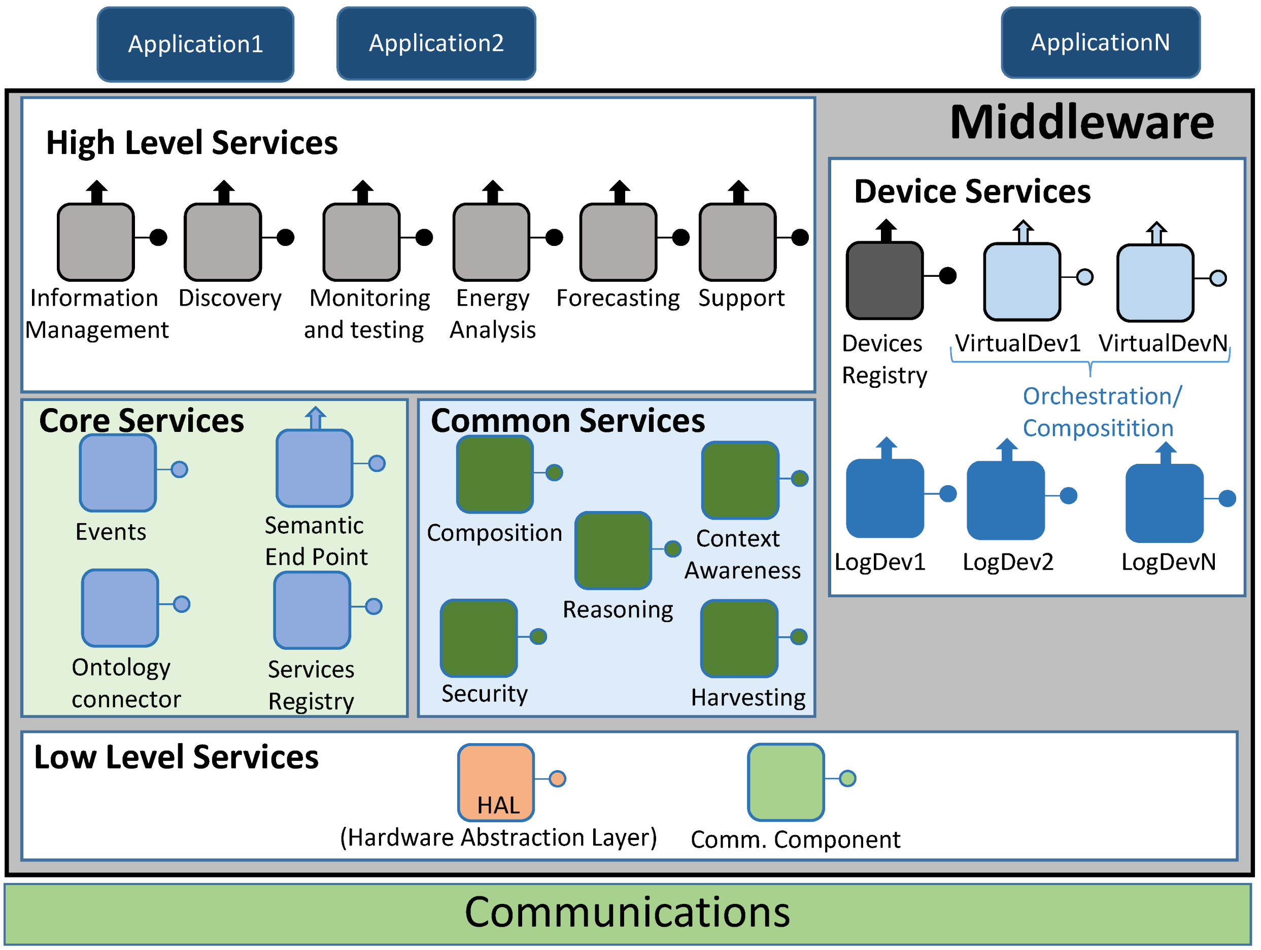
4.1.1. High Level Services
- Information Management. It checks whether the information that has been retrieved by the middleware as an answer to a request matches the structure of the inner service ontology that the architecture is using;
- Discovery. It is used to let the end user know what services are available, both in the middleware architecture and related to the hardware devices that are part of the system;
- Monitoring and testing. It is used as a way to test the current status of the services that can be employed. Besides, it will be the most usual high level service to be executed when a pilot interface is managed;
- Energy analysis. When requests involving specific data about energy are done, this high level service will come in handy to direct the data request;
- Forecasting. Much like energy analysis, this high level service will be used whenever there is a request related with forecasting information;
- Support. This high level middleware service is conceived for ancillary functionalities that are particular of the hardware device where the middleware architecture is deployed. If the monitoring and testing component is not enough by itself, Support high level service may be used as well.
4.1.2. Core Services
- Events. As the middleware architecture used may use protocols that follow a publish/subscribe paradigm (for example, Advance Message Queuing Protocol or AMQP), it is useful to have a component to handle this sort of communications;
- Semantic Endpoint. It offers compatibility between devices that do not use the middleware ontology and the remaining parts of the middleware architecture;
- Ontology connector. It is used as a way to map the information retrieved from the devices and services into a semantic-compliant data model used within the middleware architecture;
- Service Registry. Its main functionality is the registry of the services that, instead of being obtained from outer devices, are part of the middleware. Besides, they will be semantically registered by means of the operations made by the Ontology Connector.
4.1.3. Device Services
- Devices Registry. It carries out the actions required to register a Logical Device and integrate it as part of the whole deployment. In addition to that, it will keep a strong connection with the deployed Logical Devices by means of heartbeat messages that will be sent to the Device Registry service. It must be noted that since Device Registry will be used with device services and Service Registry with middleware services, they are using different pieces of information;
- Logical Devices. Used to represent the hardware devices that take part in the whole system. They are also used as service containers, depending on the sensors and capabilities that physical devices are equipped with. In addition to encapsulate hardware device features, they also provide a way to be deployed as compressed files in Fuse ESB-friendly locations, as explained later. The inclusion of Logical Devices in the architecture was decided after considering the Virtual Entities and Services defined in Internet of Things Architecture (IoT-A) [36];
- Virtual Devices. Virtual Devices result by merging two or more Logical Devices into a single one that will offer composed services dependent on the ones provided by Logical Devices. For example, a Logical Device offering a “temperature” service, and another one providing a “humidity” service can be merged into a third, different one named “environmental conditions” service that can be used to evaluate to probability of getting moss plants in one room.
4.1.4. Common Services
- Composition. It becomes of major importance when Virtual Devices are formed, as it will be the one used for this task;
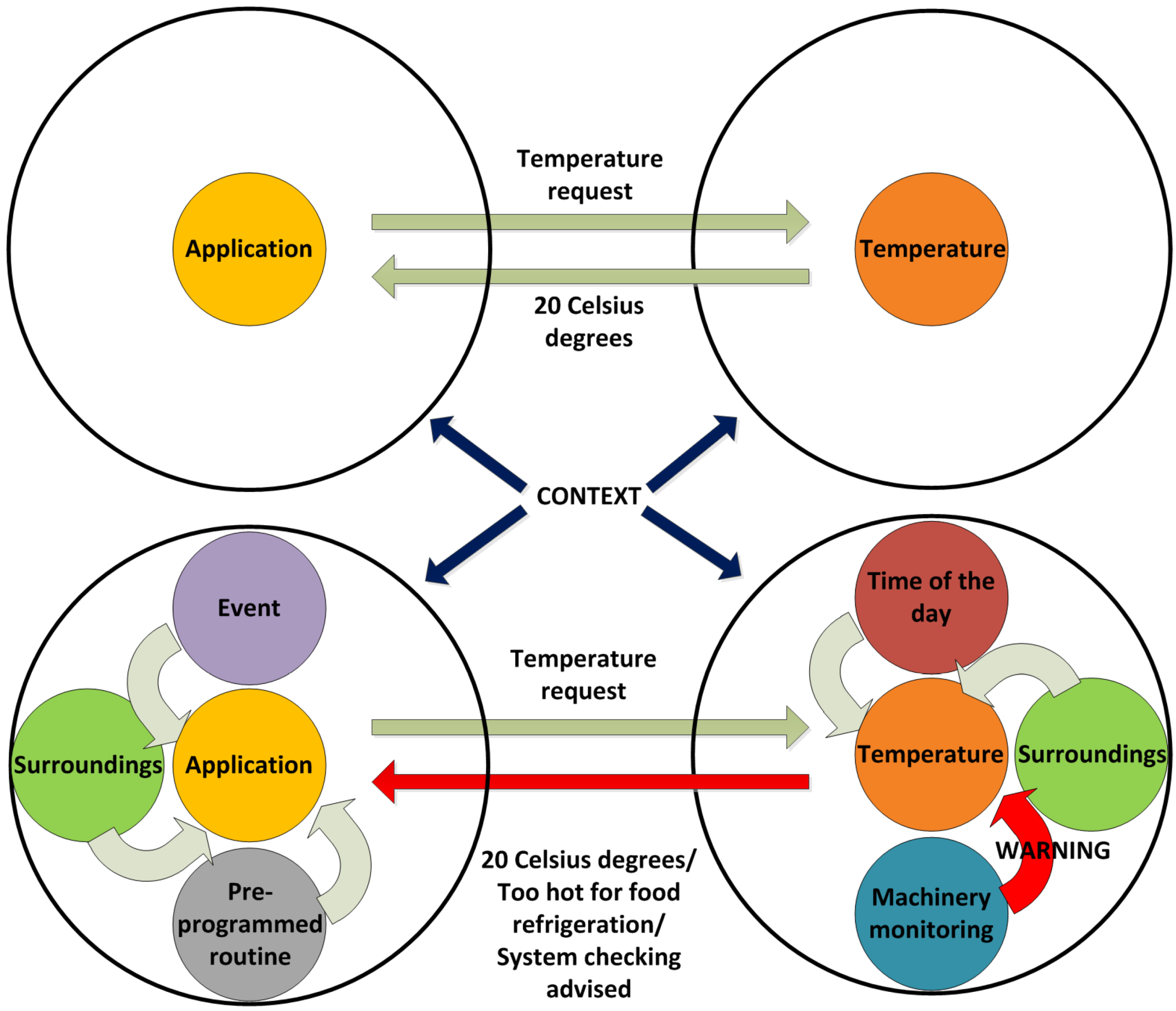
- Context awareness. It will be responsible for using retrieved information about the current status of the overall system, taking into account if there is any faulty performance so as to fix it;
- Reasoning. When required, it will work jointly with Context Awareness to provide decision making mechanisms;
- Security. It is a component devoted to functionalities and extra needs involving security. It provides features as integrity, privacy or authenticity, albeit the extra features required in this component will have to be met at the application and/or hardware levels;
- Harvesting. This service collects the information obtained from the Low Level services and transfers it to the upper layers of the middleware architecture.
4.1.5. Low Level Services
- Hardware Abstraction Layer (HAL). Its main usage point is to abstract all the hardware-specific features that may be found as part of the hardware components of the deployment;
- Communications component. It is the actual interface between the communications layer protocol and the middleware architecture. Depending on the protocol used outside the middleware, it may use interfaces adapted to the communications protocol used (Java Message Service or JMS, AMQP, etc.).
4.2. Implementation Software Facilities
4.2.1. Fuse Enterprise Service Bus
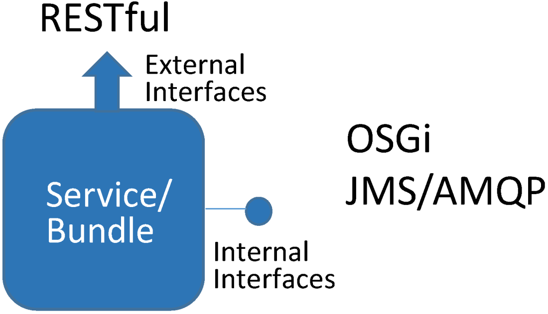
4.2.2. Service Interfaces Types

4.2.3. Operation Protocol Messages
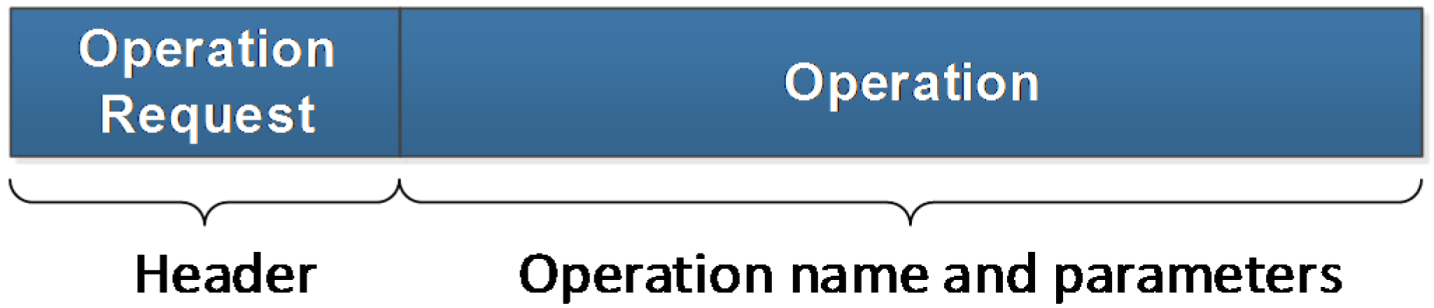
- Operation Request: by following a client-server paradigm, they will be sent from a Fuse ESB bundle acting as the client and received by a different bundle acting as the server. This message is made up by two fields:
- a)
- Message type: it identifies what kind of message is being transferred;
- b)
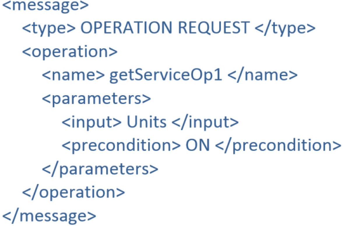
- Operation: this field encases the operation significant characteristics, namely the operation name and the input parameters. Furthermore, if any precondition is required for the operation to be triggered, it will be included as well.
The message appearance has been depicted in Figure 8.Figure 8. Operation request message.![Energies 07 05953 g008]() An example of the XML-formatted message that is being transmitted looks as presented in Figure 9.Figure 9. Operation request eXtensive markup language (XML) example.
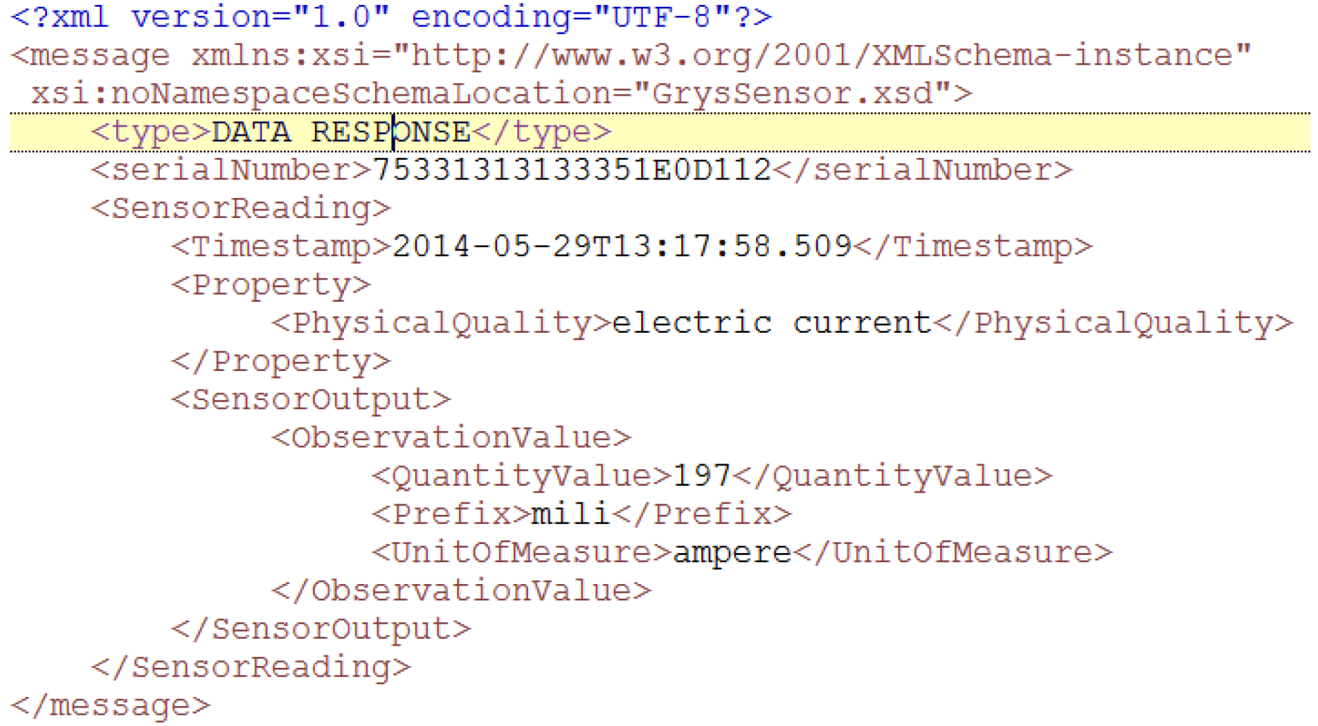
An example of the XML-formatted message that is being transmitted looks as presented in Figure 9.Figure 9. Operation request eXtensive markup language (XML) example.![Energies 07 05953 g009]()
- Operation Response: it is the natural counterpart of the Operation Request message, the one that is sent from the server bundle to the client one as an answer. As the former one, it is divided in two different parameters:
- a)
- Message type: it identifies the kind of message that is being interchanged between bundles;
- b)
- Operation: its content resembles Operation Request message, albeit the parameters that are contained are the output returned value instead of the inputs that were sent before.
4.3. Semantic Features

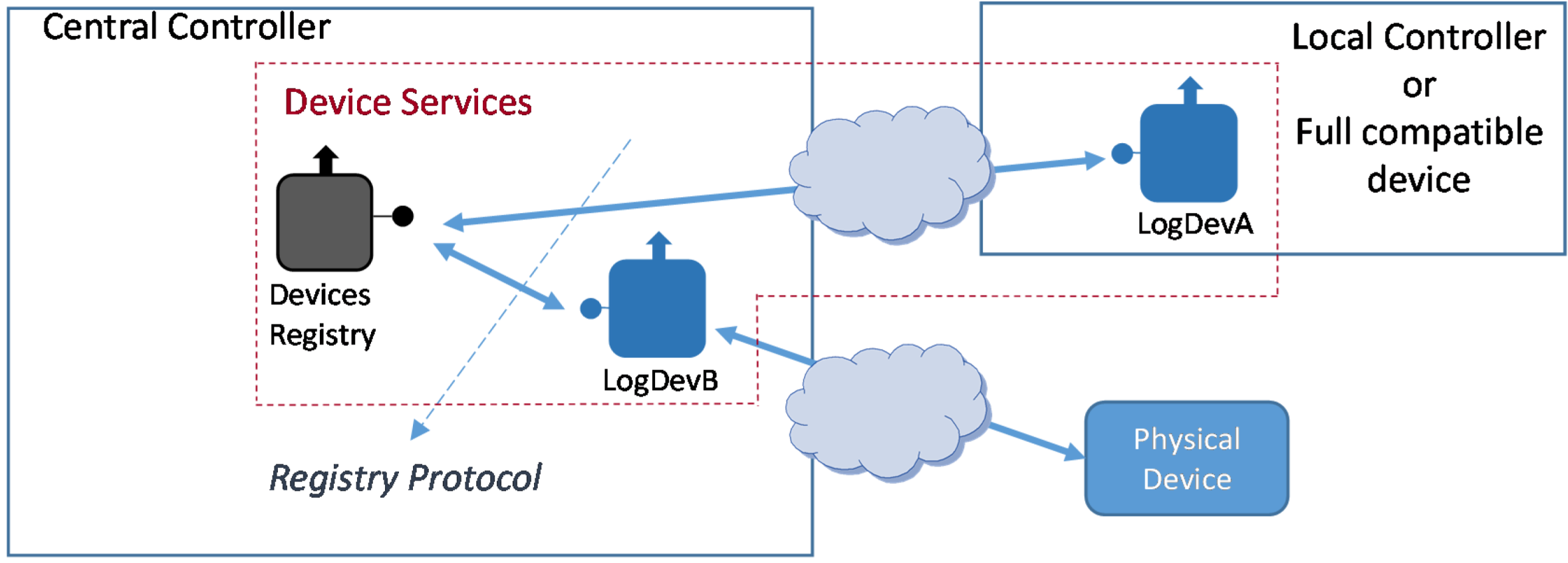
4.4. Device Registry
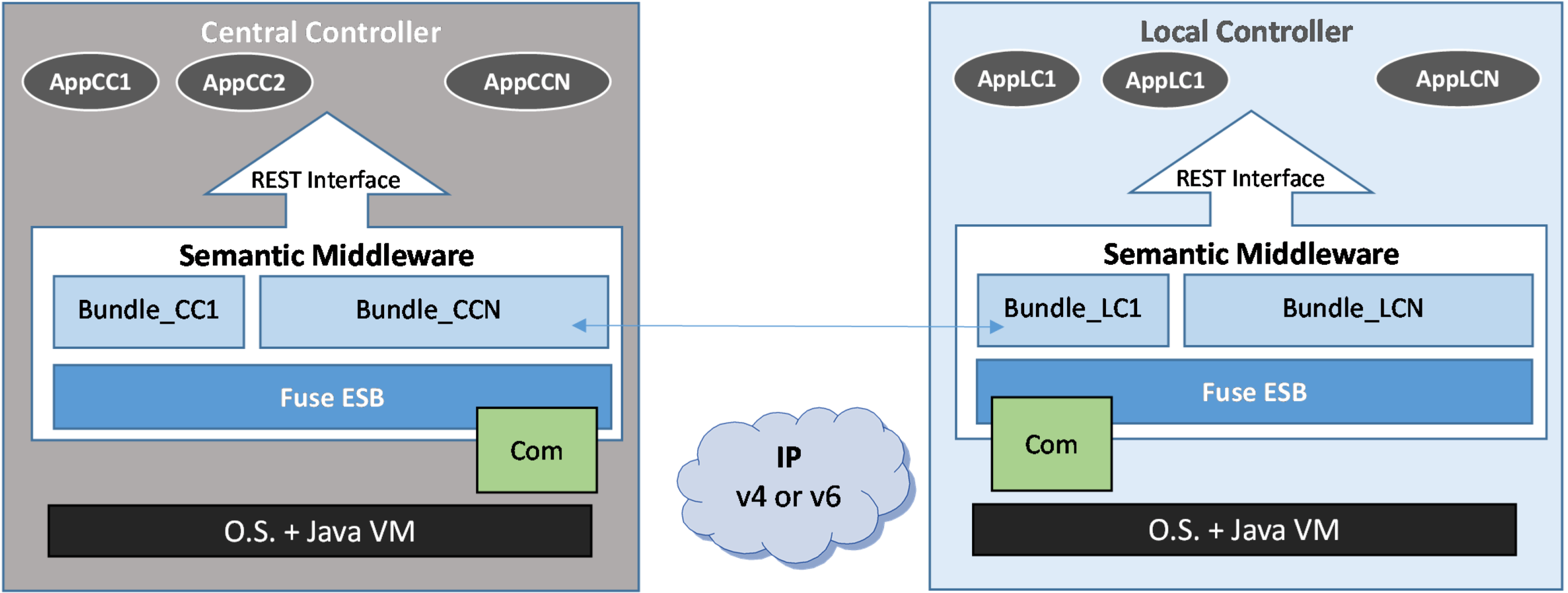
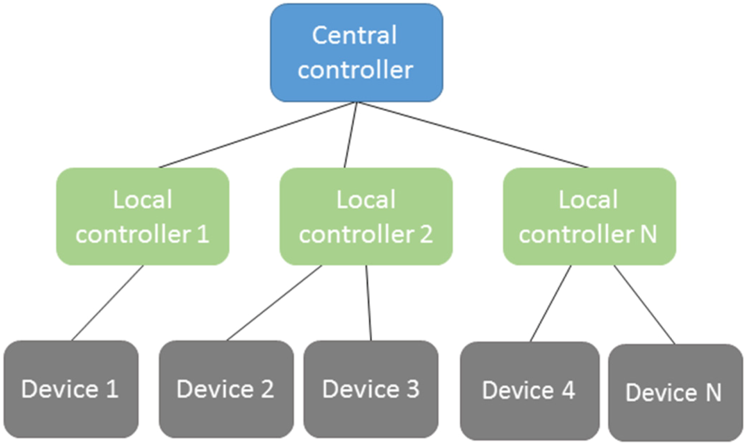
- Logical Device Type A. It will be implemented as part of the Local Controller. Since the Local Controller will be effectively a device accessible enough to install the Logical Device, it can be regarded as a full middleware-compliant device (e.g., LogDevA in Figure 12);
- Logical Device Type B. Unlike type A, this Logical Device is implemented outside the device it is bound to; in fact, it will be usually implemented at the Central Controller (e.g., LogDevB in Figure 12). This option will be used, for example, when the physical device is not computationally capable of having a functional middleware installation.

4.4.1. Registry Protocol
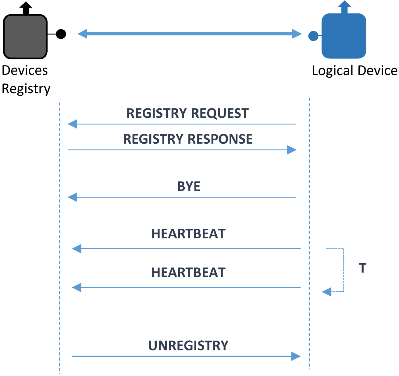
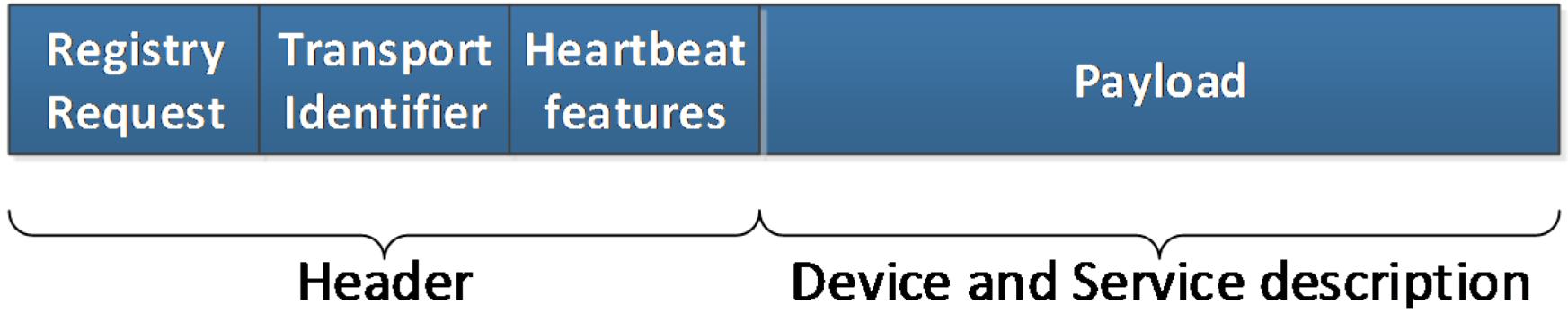
- Registry Request. It is the message used to integrate a Logical Device. In this message there will be data required to send the request. These data are:
- a)
- Message type: it has the same functionality as before: identifying the kind of message that is being transferred;
- b)
- Transport identifier: used to particularize a device according to lower layer parameters, such as an IP address. It has been conceived as an optional parameter, as it is used just in case lower layers do not provide a way to get a sender identifier;
- c)
- Heartbeat features: used so as to confirm that once the registration has taken place, the devices that have been registered will send messages to guarantee that they remain functional and can perform their assigned tasks. As related in [42], using a dynamic procedure to send these messages that is aware of the success or failure of the device performance is advisable. Consequently, heartbeat messages will be given the opportunity to be sent at a decreasing rate, as long as all the previous ones have reached its destination successfully. Different algorithms can be used as well; if the value field has zero as a value, a constant periodic amount of time will be used between messages, otherwise some other ways of transmitting heartbeat messages can be used;
- d)
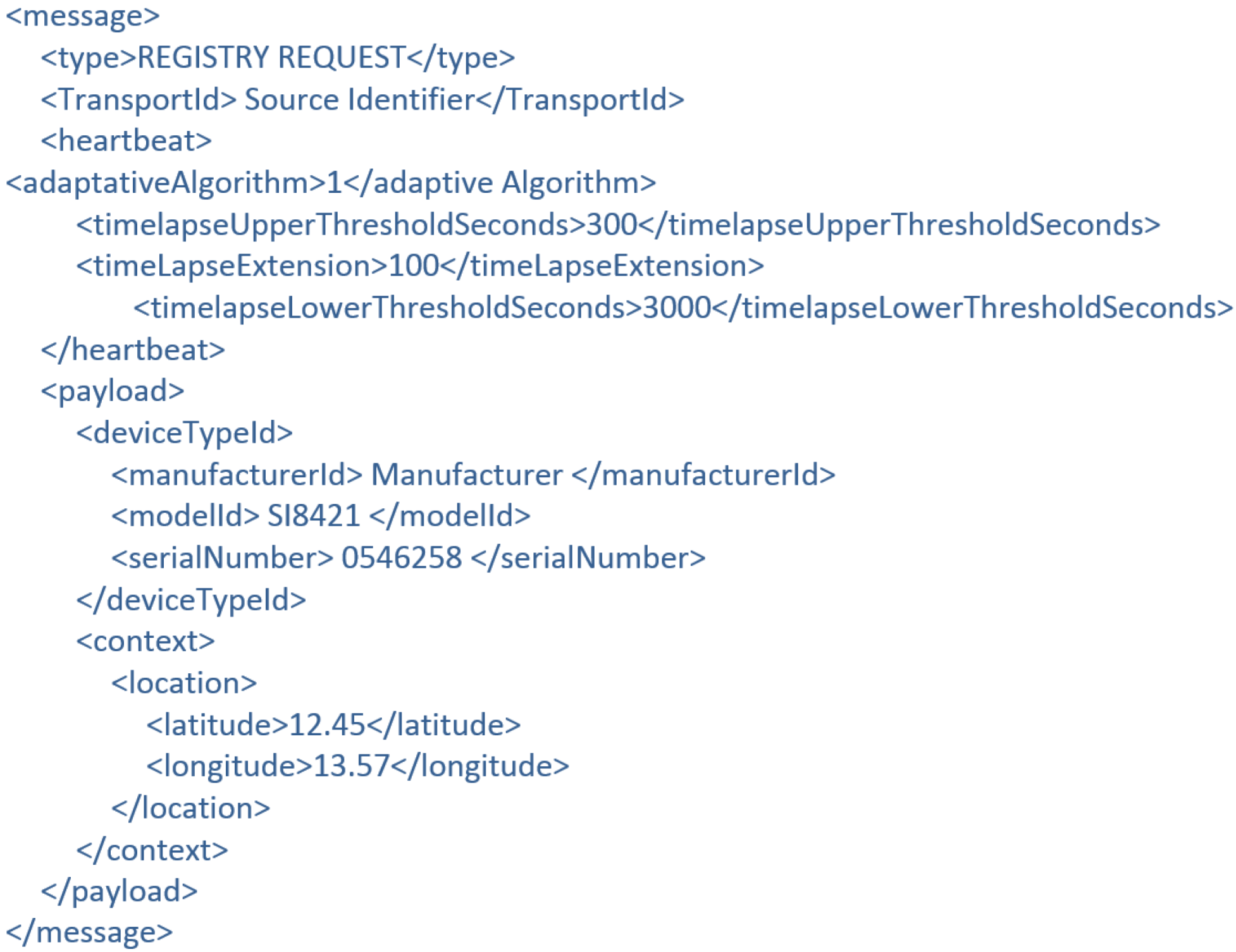
- Payload: among the contents of this field there will be a physical device unique identifier (labeled as deviceTypeID in the XML representation of this message) and context sensitive data. By means of deviceTypeID information—which is providing the device manufacturer, model and serial number—one template will be used to complete the semantic registration of the device, as it will be described in section 4.4.3. This template will be filled up with information from the Logical Device and sent to the Ontology Connector so as to have the device semantically stored.
The appearance of this message will be as represented in Figure 14.Figure 14. Registry request message.![Energies 07 05953 g014]() Additionally, the XML representation of the message resembles the ones that were depicted in Figure 15. As it can be noted, heartbeat characteristics have been added as well.Figure 15. Device registry request XML example.
Additionally, the XML representation of the message resembles the ones that were depicted in Figure 15. As it can be noted, heartbeat characteristics have been added as well.Figure 15. Device registry request XML example.![Energies 07 05953 g015]()
- Registry Response. Used to confirm that the registration process was completed. It is sent from the Device Registry to the Logical Device that sent a Registry request before;
- Bye. This is a message sent when a Logical Device chooses voluntarily to be disconnected from the system (instead of being forced out by an accident or any other malfunctioning issues);
- Unregister. This message is quite similar to Bye with a difference in the direction it is transferred: instead of travelling from the Logical Device to the Device Registry, it will go the other way round, as the action of disconnecting the device from the system will be taken by the Device Registry;
- Heartbeat. This message will be the one that is used by the Logical Device to send a periodical acknowledgment of the good performance of the system.
4.4.2. Registering Physical Devices

- The physical device sends a Phy-Registry-Request message to the Devices Registry. This message contains the same physical device unique identifier associated to the label <deviceTypeId> used in the previously described Registry Request message;
- The Devices Registry service checks if the physical device is correctly formatted and creates, if checking was successful, the right bound Logical Device;
- Once the logical device is created, it connects with its bound physical device using the appropriate communication protocol that will depend on the physical devices communication capabilities. The Logical Device will get from the physical device all the information needed to represent it within the middleware architecture.
4.4.3. Registry and Ontology

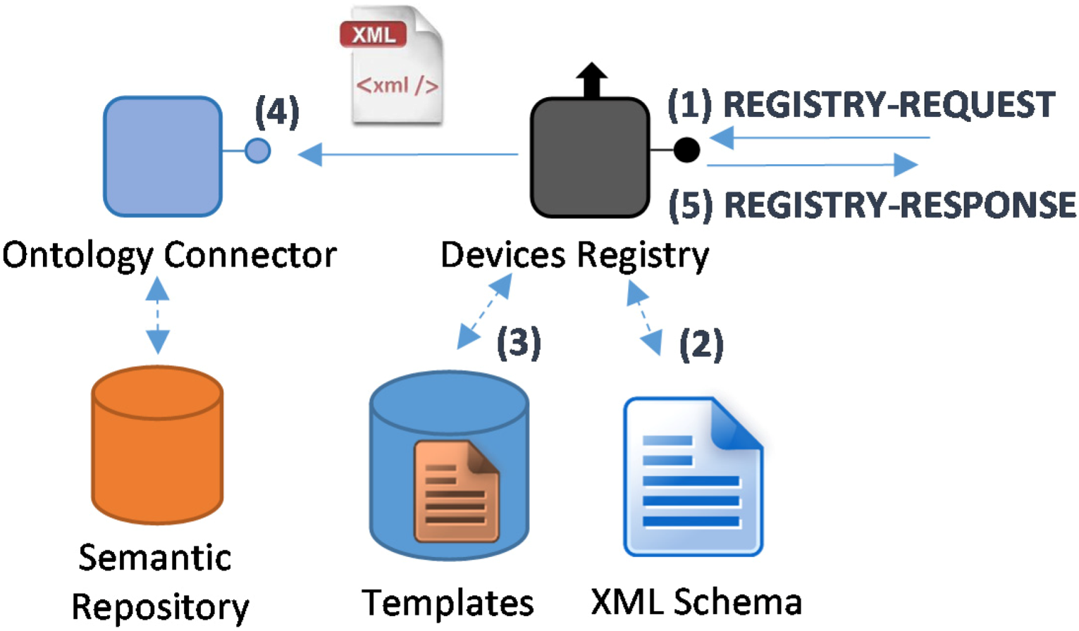
- A Request Registry for service registration will be received at the Device Registry;
- This message will have data on its payload part that will have to be validated as any other XML-formatted document. In order to do so, there will be several XMLSchemas that effectively guarantee that the information received by the Device Registry is compliant with the format that is expected from the Logical Devices;
- Semantic registration requires a template to be filled with the information once the content of the request has been validated. These templates will be pre-installed in the Central Controller with the deployed middleware architecture;
- When the template fulfilling is finished, it is sent towards the Ontology Connector using the OSGi-based interface for internal middleware communications;
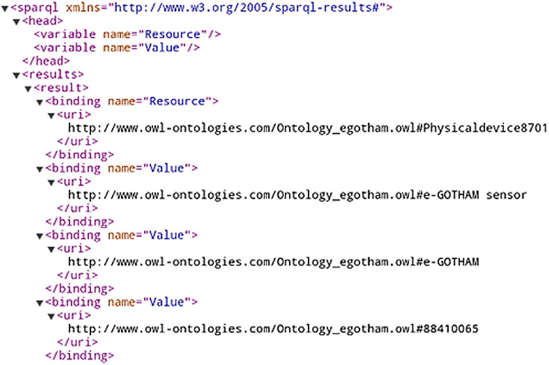
- The Ontology Connector will collect the information sent by the Device Registry and store it for its future usage. The process has been depicted in Figure 18.

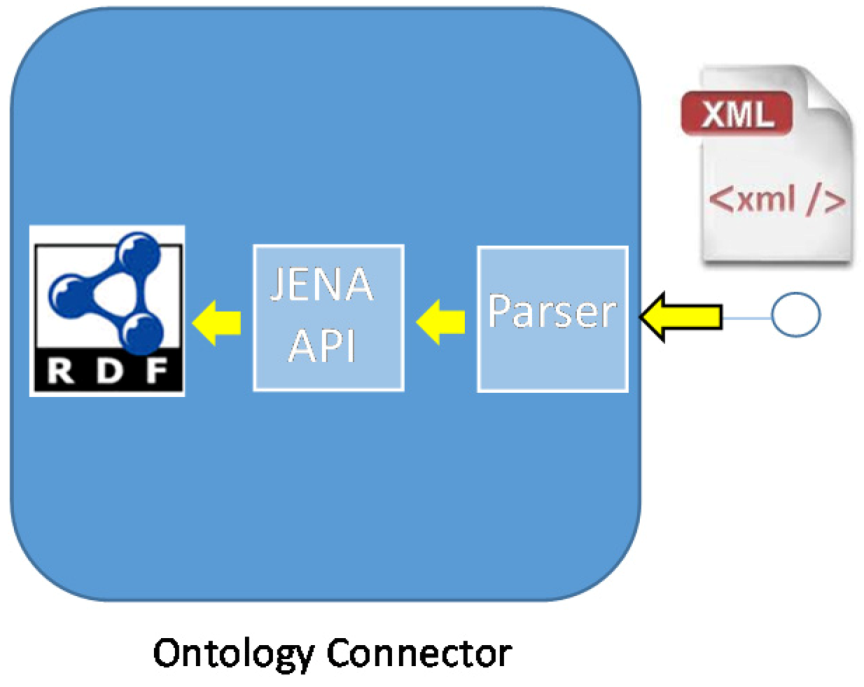
- Parsing block: when it receives the XML-formatted information it will extract the most relevant fields to have them processed by the next block;
- JENA API block: it is in charge of turning the attributes that had been collected before into RDF-formatted files that will contain the semantic information;
- RDF files: they will contain the information related with the middleware ontology. It will usually be dealing with information about the services and their capabilities.
4.5. Middleware Service Registry
- Registry Request. It is the message used to start the registration. It has two familiar fields:
- a)
- Message type: it will identify what kind of message is being sent;
- b)
- Payload: this field is containing the majority of the information required by the service. They will too make use of templates in order to determine how the content should look like in order to successfully complete the registration process.
- Registry Response. This message will be sent back to the service that sent the registry request in the first place. The data that is part of the message are:
- a)
- Message type: it defines the kind of message that is sent from one bundle to another;
- b)
- Payload: it contains the information related with the result of the registry process.
4.6. Context Awareness
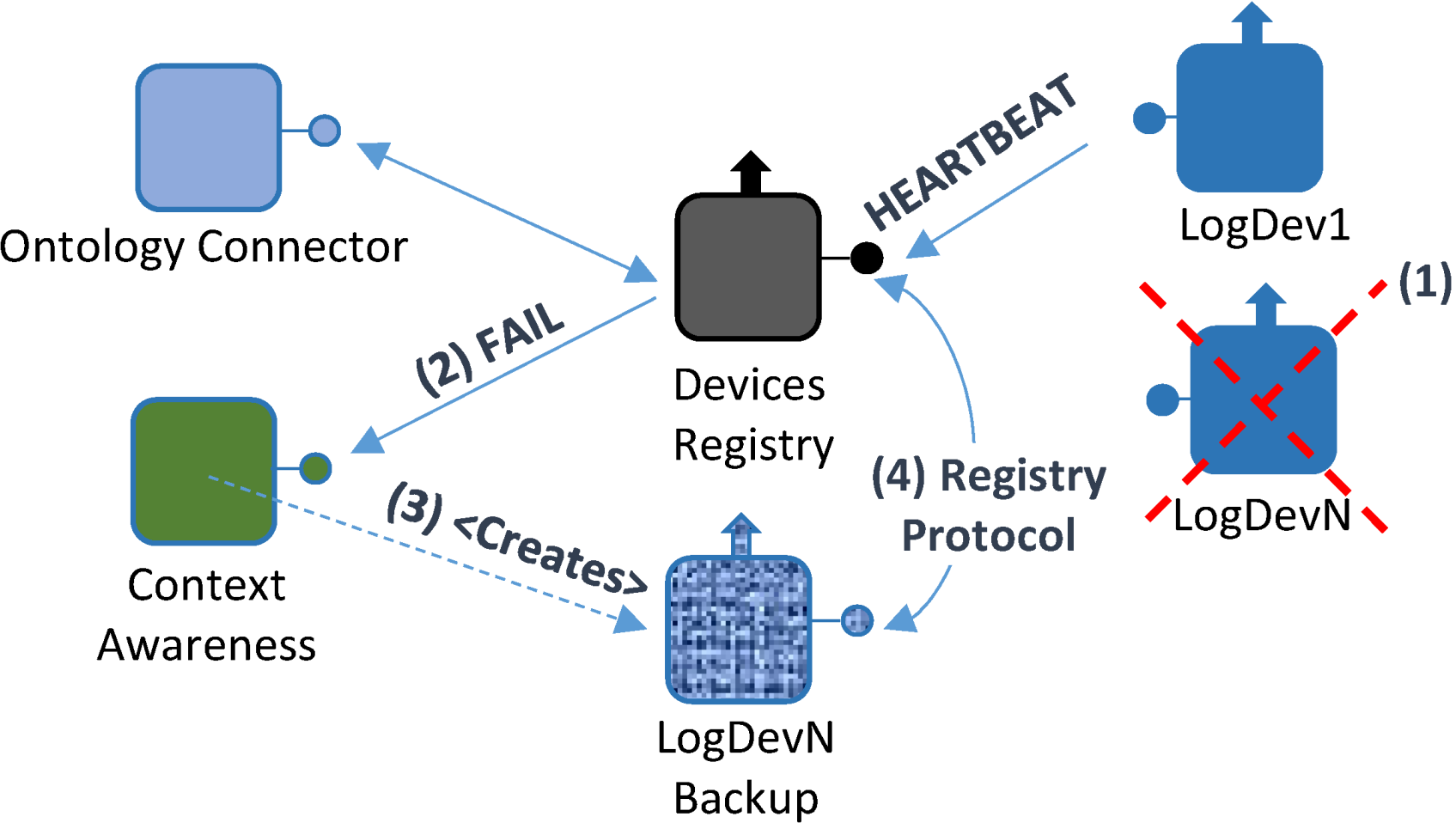
- A failure takes place in one of the devices integrated in the system; consequently, it affects the Logical Device that is bound to it (Logical Device N). Therefore, it will not be able to send any Heartbeat messages to the Device Registry;
- In the absence of Heartbeat messages, Logical Device N will be forced to send a FAIL message, containing the Logical Device N unique identifier, along with the last time when a successful heartbeat message was received;
- By using the unique identifier, a Logical Device backup will be created by the Context Awareness component, specifically created for this task according to all the functionalities that were previously contained by the Logical Device, thus creating Logical Device N Backup (LogDevN Backup);
- At this point, a lighter registry request message will be sent by LogDevN Backup to complete the registration process.
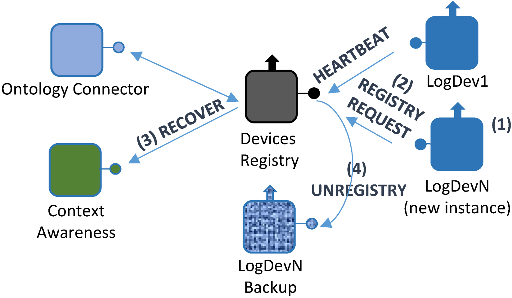
- When the LogDevN gets recovered it will start running again. Since it will have to be notified for the whole middleware architecture, the registry protocol must be initiated;
- LogDevN will be registered. At this very moment, LogDevN Backup will no longer be necessary; a Recover message will be sent from the Device Registry component to the Context Awareness one so as to notify the changes in the existing Logical Devices;
- Also, this change is notified at the Ontology Connector. It will edit the ontology contents in order to update it to the new current situation;
- Finally, the Logical Device that was used as a backup will be unregistered. For this purpose, a message to unregister the backup Logical Device.
4.7. Service-Related Functionalities
5. Performance Tests and Behavior
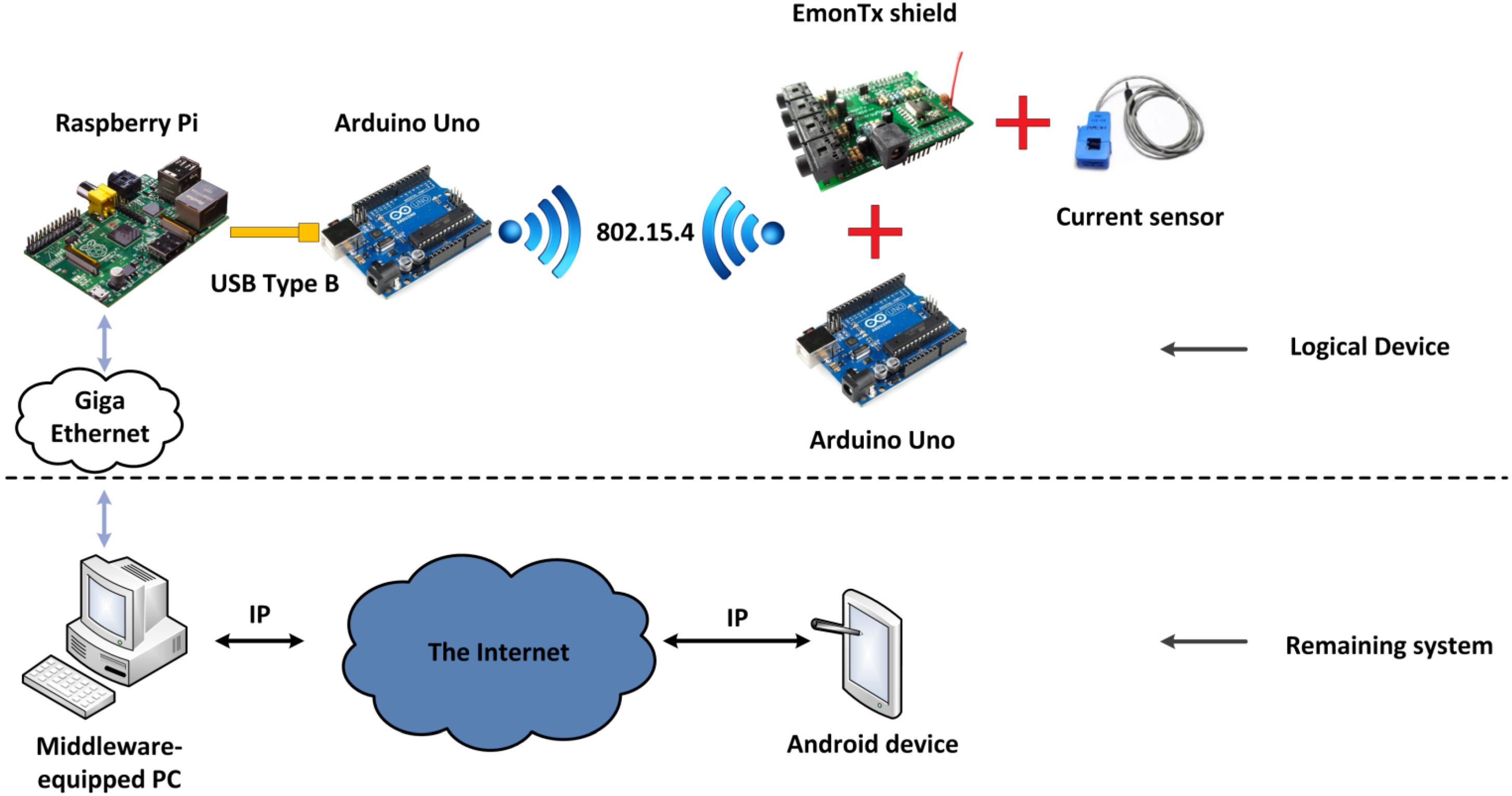
- Hardware level. Basically, it represents the hardware elements that make up a Logical Device running in a Local Controller. It has a significant degree of heterogeneity, for the physical devices that make a Logical Device can be varied and there is no direct equivalence between the Logical Device and the number of devices involved in this representation. Five pieces of hardware are present here: a) a current sensor that uses Hall effect to its advantage in order to measure power usage; b) an electrical current measurement shield called EmonTx Arduino shield, manufactured by OpenEnergyMonitor, a company that manufactures electronic devices with a relevant degree of openness and Do-It-Yourself procedures [44] with an appearance as shown in Figure 24; c) two Arduino Uno boards, which provide the required amount of pins and capabilities needed for the information transmission in the prototype, one will be used to attach the shield and receive the data from it to send it via 802.15.4 communications to the other one, which will be gathering the data to send it and d) a Raspberry Pi, which both transfers the gathered data and is used as part of the PC that has installed the middleware architecture as a distributed server, where the most resource-demanding operations will be run in order to keep the Raspberry Pi functional in each moment;Figure 24. EmonTx Arduino shield mounted over an Arduino Uno.
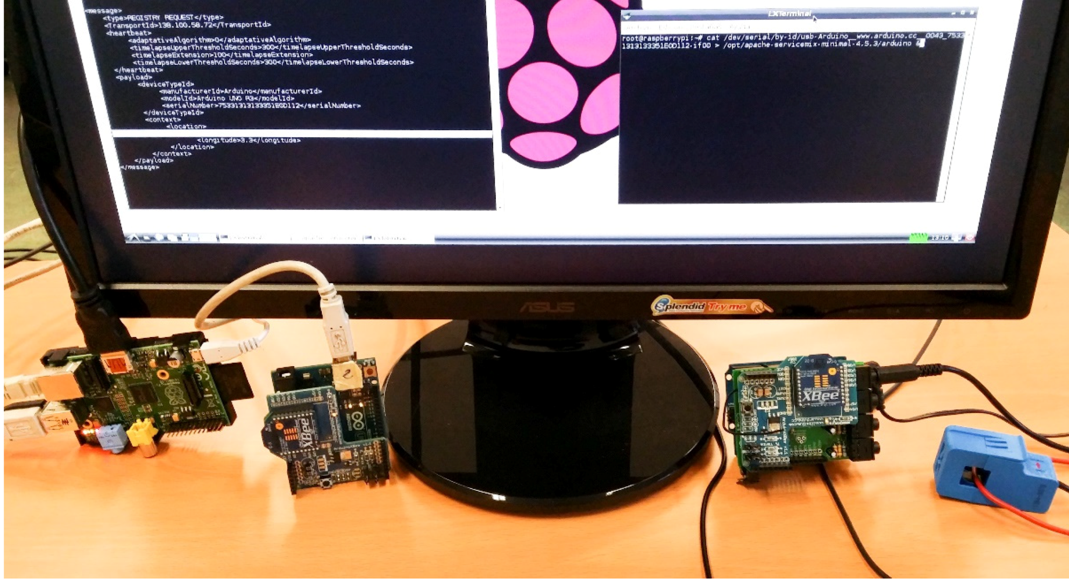
![Energies 07 05953 g024]() The overall appearance of the assembly involving the different hardware devices that would be mapped as a Logical Device can be seen in Figure 25. The different wired and wireless protocols were integrated without showing signs of defective performance.Figure 25. Hardware equipment used for current measurement.
The overall appearance of the assembly involving the different hardware devices that would be mapped as a Logical Device can be seen in Figure 25. The different wired and wireless protocols were integrated without showing signs of defective performance.Figure 25. Hardware equipment used for current measurement.![Energies 07 05953 g025]()
- Communications level. There are two different kinds of communications: on the one hand, standard IEEE 802.15.4 is used as a local, wireless one to transmit data from the shield-connected current sensor to the Arduino Uno. On the other hand, regular Internet connections will be enabled so as to use them to be accessed via REST interfaces. In a nutshell, the Wireless Sensor Network-like scenario will use IEEE 802.15.4 for communications, and the remaining parts of the deployment use the Internet Protocol;
- Middleware level. A computer is used as the Central Controller with the middleware components already described: a Fuse ESB with several bundles running inside, each of them containing the services that are used, and the Logical Devices representing the hardware pieces that belong to the system;
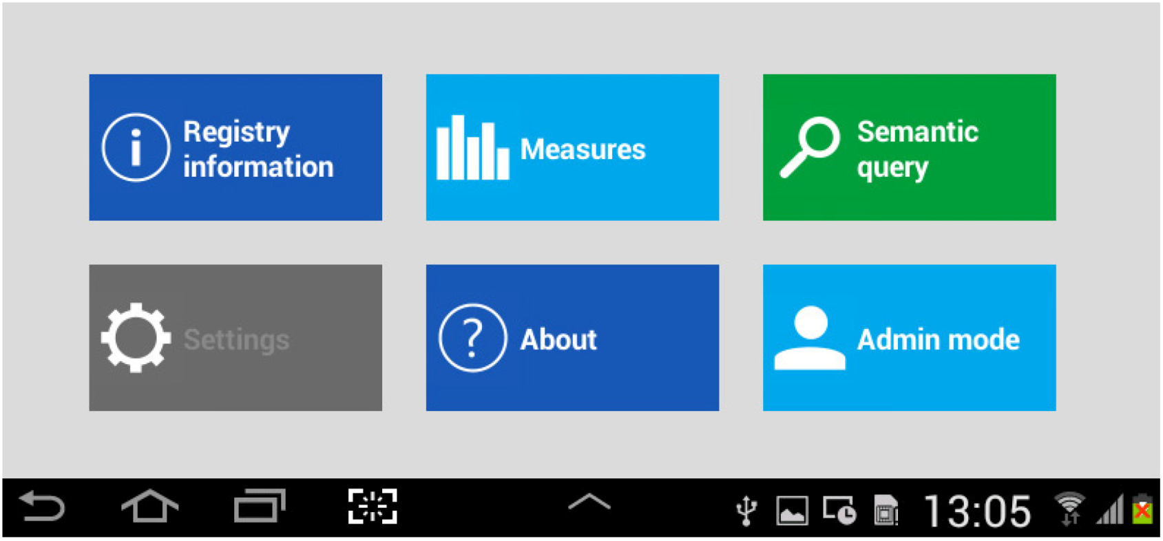
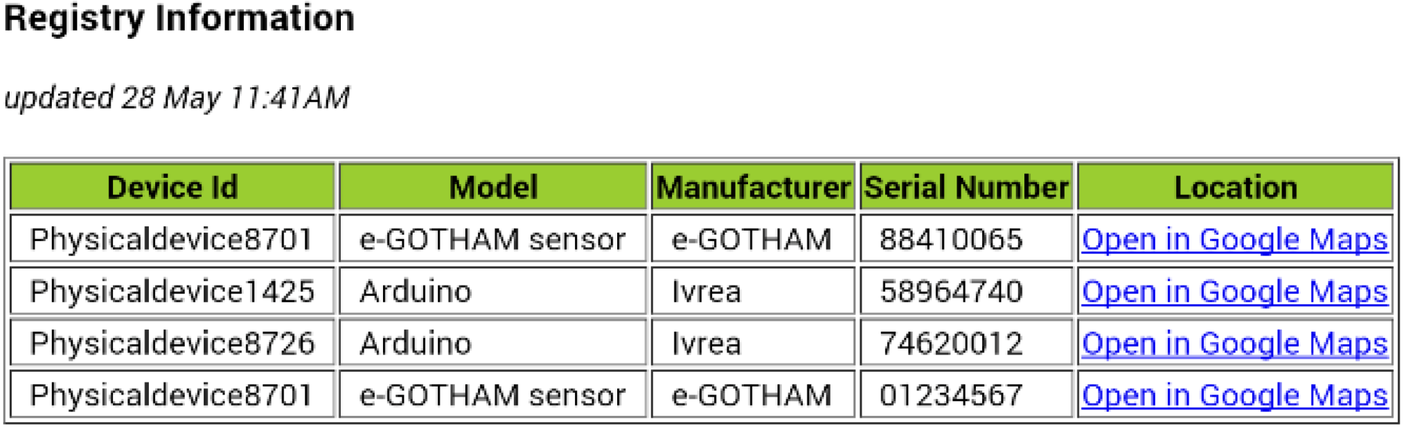
- Application level. A web browser was used to obtain the information and have it readable. As depicted before, an REST-connected Android application was also employed to monitor which devices are registered, what services they are capable of providing, and regular service requests. Also, the time required to register a device (that is to say, creating a logical device that will become semantically registered) was tested.


5.1. Measures and Discussion
| Counter | Value | Timestamp |
|---|---|---|
| 1 | 71 | 2014-05-30T15:19:44.029 |
| 2 | 67 | 2014-05-30T15:19:46.351 |
| 3 | 71 | 2014-05-30T15:19:48.778 |
| 4 | 82 | 2014-05-30T15:19:52.25 |
| 5 | 112 | 2014-05-30T15:19:56.211 |
| Equipment characteristics | |
|---|---|
| Middleware-equipped personal computer | CPU Intel® Core™ i3-3240 @3,4GHz, RAM 8Gbytes, Ubuntu 12.04 LTS running on VMware Player 4.0.6 |
| Raspberry Pi | Model B, 512 Mbytes. |
| PC2 used alternatively to Raspberry Pi to run the logical device. | CPU Intel® Core™ 2 6400@2.14GHz, RAM 3Gbytes, Windows 7. |
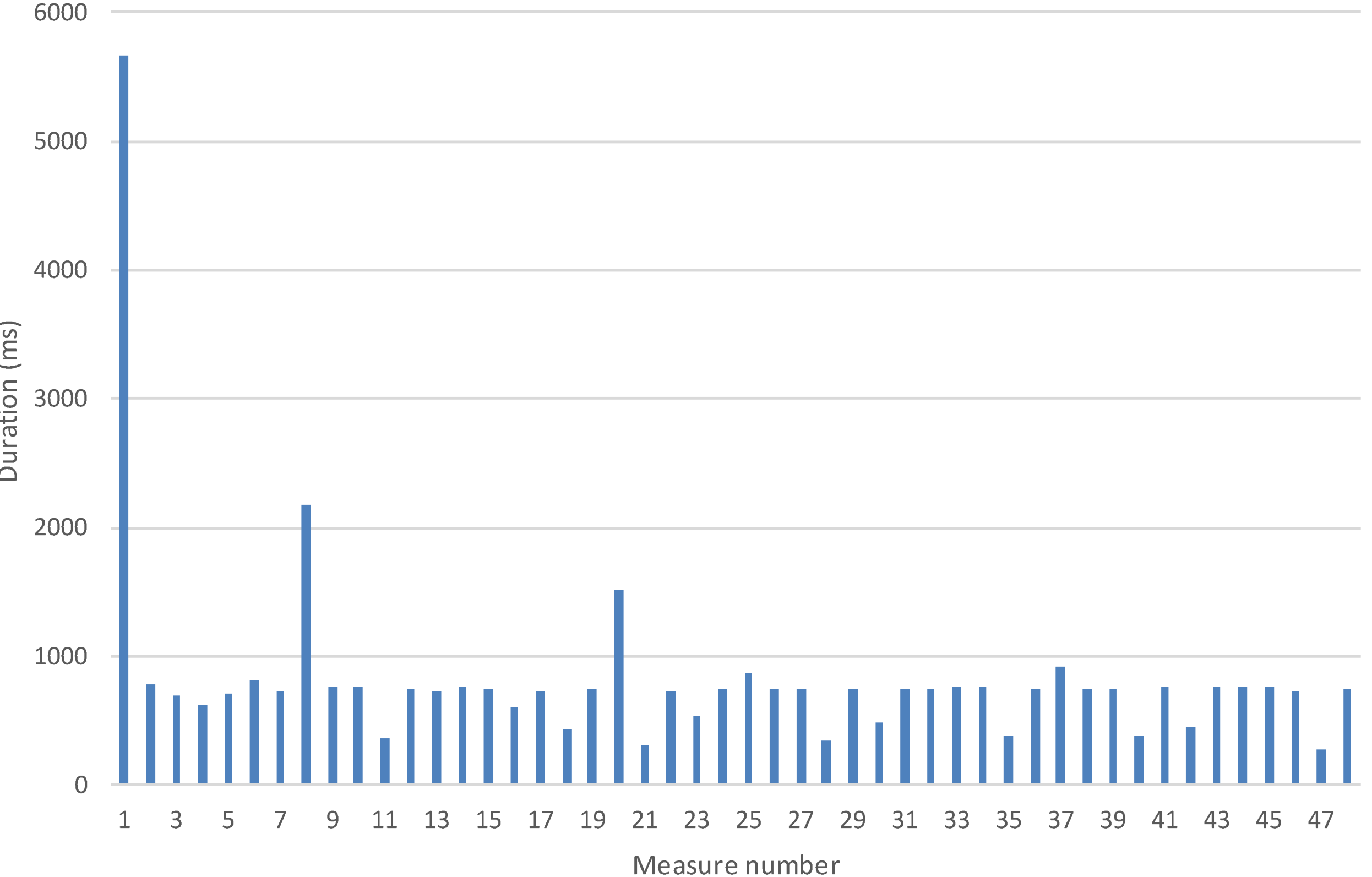
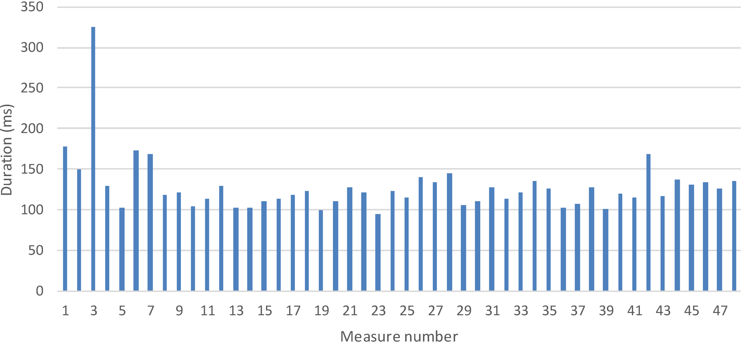
5.1.1 Time to Registry a Logical Service Measurement

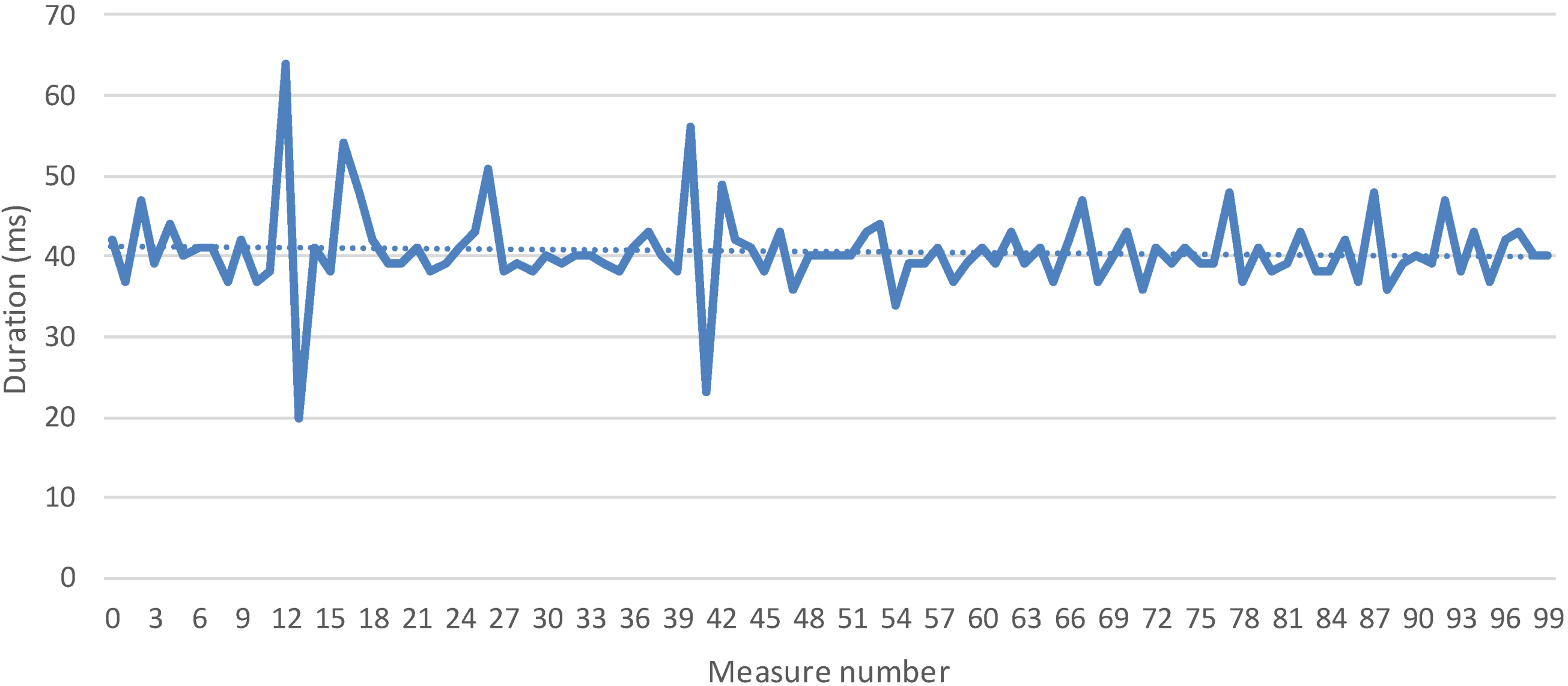
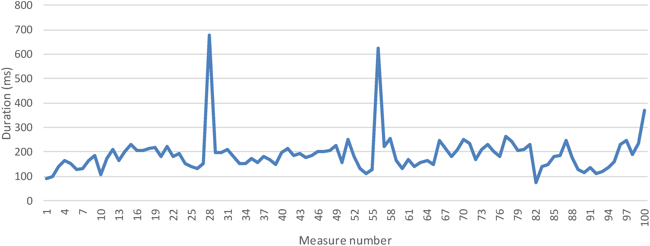
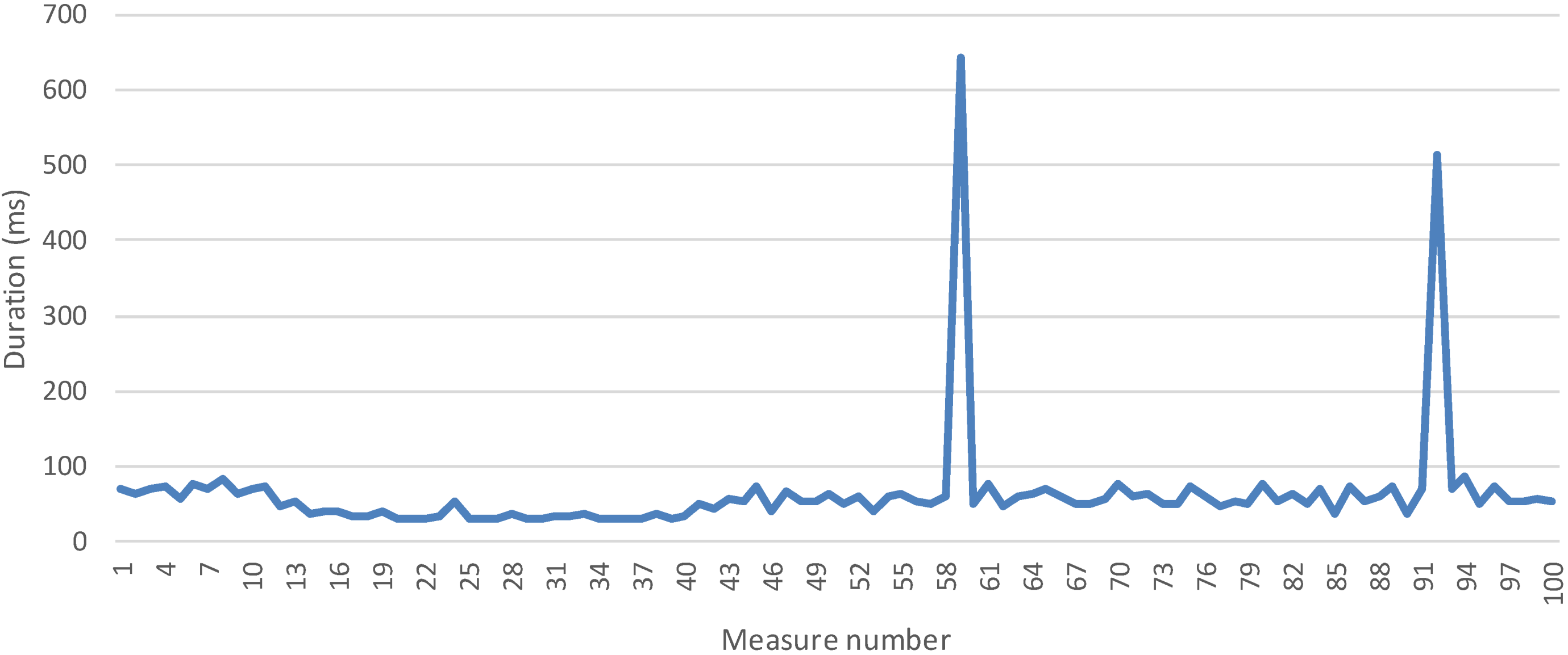
5.2.2 Time to Collect One Measurement


6. Conclusions and Future Works
- Semantic data treatment is implemented using a service-oriented ontology that is focused on services and information management regarding devices. This ontology offers smart data treatment specially adapted to the Smart Grid. It has been designed and implemented to describe all the functionalities and characteristics of the existing services in the middleware;
- A software representation of the existing devices of a system has been achieved by using Logical Devices. This solution grants a more specific device management for operations such as discovery or service registration;
- A context aware solution for device failures that provides a replacement mechanism for the Logical Device associated has been developed so as to carry on with the usual performance of the system;
- This middleware proposal follows the Service Oriented Architecture model, which provides flexible design solutions offering support for several communications mechanisms and interface creations, including external RESTful interfaces. In addition to that, the middleware components are highly autonomous, and there is a reasonable degree of portability and scalability among systems;
- Fuse ESB-based implementation solves service integration issues over a distributed and heterogeneous environment;
- The different tasks have been distributed among different elements of the layered architecture so that the addition of new Common and High Level services to solve future microgrid challenges will be less troublesome;
- Logical Devices have been proven to be able to run in medium-to-low capability devices. Since they are not dependent on the hardware that they are installed on (only a functional ESB is required), they can be ported to other devices as BeagleBone boards, etc.
Acknowledgments
Author Contributions
Conflicts of Interest
References
- United States Census Bureau—International Database. Available online: http://www.census.gov/population/international/data/idb/region.php?N=%20Results%20&T=13&A=aggregate&RT=2&Y=2013&R=301&C= (accessed on 22 August 2014).
- United States Census Bureau—International Database. Available online: http://www.census.gov/population/international/data/idb/region.php?N=%20Results%20&T=13&A=aggregate&RT=2&Y=2050&R=301&C= (accessed on 22 August 2014).
- United States Census Bureau—International Database. Available online: http://www.census.gov/population/international/data/idb/region.php?N=%20Results%20&T=13&A=aggregate&RT=2&Y=2030&R=301&C= (accessed on 22 August 2014).
- Global Health Observatory (GHO)—Urban population growth. Available online: http://www.who.int/gho/urban_health/situation_trends/urban_population_growth_text/en/ (accessed on 22 August 2014).
- Sinha, A.; Neogi, S.; Lahiri, R.N.; Chowdhury, S.; Chowdhury, S.P.; Chakraborty, N. Smart grid initiative for power distribution utility in India. In Proceedings of the 2011 IEEE Power and Energy Society General Meeting, San Diego, CA, USA, 24–29 July 2011; pp. 1–8.
- Valsamma, K.M. Smart Grid as a desideratum in the energy landscape: Key aspects and challenges. In Proceedings of the 2012 IEEE International Conference on Engineering Education: Innovative Practices and Future Trends (AICERA), Kottayam, India, 19–21 July 2012; pp. 1–6.
- Shafiei, S.E.; Rasmussen, H.; Stoustrup, J. Modeling supermarket refrigeration systems for demand-side management. Energies 2013, 6, 900–920. [Google Scholar] [CrossRef]
- Gungor, V.C.; Sahin, D.; Kocak, T.; Ergut, S.; Buccella, C.; Cecati, C.; Hancke, G.P. Smart grid technologies: Communication technologies and standards. Ind. Inform. IEEE Trans. 2011, 7, 529–539. [Google Scholar] [CrossRef]
- Wendt, A.; Faschang, M.; Leber, T.; Pollhammer, K.; Deutsch, T. Software architecture for a smart grids test facility. In Proceedings of the 39th Annual Conference of the IEEE Industrial Electronics Society (IECON 2013), Vienna, Austria, 10–13 November 2013; pp. 7062–7067.
- Schneider Electric—Smart Grid solutions. Available online: http://www.schneider-electric.com/products/ww/en/?Business=10 (accessed on 13 August 2014).
- Ustun, T.S.; Hadbah, A.; Kalam, A. Interoperability and interchangeability considerations in microgrids employing IEC61850 standard. In Proceedings of the 2013 IEEE International Conference on Smart Energy Grid Engineering (SEGE), Oshawa, ON, Canada, 28–30 August 2013; pp. 1–5.
- NIST Framework and Roadmap for Smart Grid Interoperability Standards, Release 1.0; NIST Special Publication 1108. National Institute of Standards and Technology (NIST): Gaithersburg, MD, USA, January 2010. Available online: http://www.nist.gov/public_affairs/releases/upload/smartgrid_interoperability_final.pdf (accessed on 13 August 2014).
- Akribopoulos, O.; Georgitzikis, V.; Protopapa, A.; Chatzigiannakis, I. Building a platform-agnostic wireless network of interconnected smart objects. In Proceedings of the 2011 15th Panhellenic Conference on Informatics (PCI), Kastonia, Greece, 30 September–2 October 2011; pp. 277–281.
- Aguiar, J.; Götz, J.; Mosshammer, R.; Soriano, R.; Leménager, F.; Gouveia, P. DER and OpenNode: Integration of DG in an open architecture for secondary nodes in the smart grid. In Proceedings of the CIRED 2012 Workshop on Integration of Renewables into the Distribution Grid, Lisbon, Portugal, 29–30 May 2012; pp. 1–4.
- W3C Consortium—Resource Description Framework (RDF). Available online: http://www.w3.org/RDF/ (accessed on 18 August 2014).
- Penya, Y.K.; Nieves, J.C.; Espinoza, A.; Borges, C.E.; Peña, A.; Ortega, M. Distributed semantic architecture for smart grids. Energies 2012, 5, 4824–4843. [Google Scholar] [CrossRef]
- Makris, P.; Skoutas, D.N.; Skianis, C. A survey on context-aware mobile and wireless networking: On networking and computing environments’ integration. Commun. Surv. Tutor. IEEE 2013, 15, 362–386. [Google Scholar]
- Liang, H.; Choi, B.J.; Zhuang, W.; Shen, X.; Awad, A.S.A.; Abdr, A. Multiagent coordination in microgrids via wireless networks. Wirel. Commun. IEEE 2012, 19, 14–22. [Google Scholar]
- Fang, X.; Yang, D.; Xue, G. Evolving smart grid information management cloudward: A cloud optimization perspective. Smart Grid IEEE Trans. 2013, 4, 111–119. [Google Scholar] [CrossRef]
- Mehmood, Y.; Habiba, U.; Shibli, M.A.; Masood, R. Intrusion Detection System in Cloud Computing: Challenges and opportunities. In Proceedings of the 2013 2nd National Conference on Information Assurance (NCIA), Rawalpindi, Pakistan, 11–12 December 2013; pp. 59–66.
- Liang, H.; Tamang, A.K.; Zhuang, W.; Shen, X.S. Stochastic information management in smart grid. Commun. Surv. Tutor. IEEE 2014, 16, 1746–1770. [Google Scholar] [CrossRef]
- Baek, J.; Vu, Q.H.; Jones, A.; Al Mulla, S.; Yeun, C.Y. Smart-frame: A flexible, scalable, and secure information management framework for smart grids. In Proceedings of the 2012 International Conference for Internet Technology And Secured Transactions, London, UK, 10–12 December 2012; pp. 668–673.
- Zhou, Q.; Natarajan, S.; Simmhan, Y.; Prasanna, V. Semantic information modeling for emerging applications in smart grid. In Proceedings of the 2012 Ninth International Conference on Information Technology: New Generations (ITNG), Las Vegas, NV, USA, 16–18 April 2012; pp. 775–782.
- Jena Ontology API. Available online: http://jena.apache.org/documentation/ontology/ (accessed on 18 August 2014).
- Common Information Model (CIM). Available online: http://www.dmtf.org/standards/cim (accessed on 18 August 2014).
- Lee, J.; Kim, Y.; Hahn, J.; Seo, H. Customer energy management platform in the Smart Grid. In Proceedings of the 2012 14th Asia-Pacific Network Operations and Management Symposium (APNOMS), Seoul, Korea, 25–27 September 2012; pp. 1–4.
- Zhou, L.; Rodrigues, J.J.P.C. Service-oriented middleware for smart grid: Principle, infrastructure, and application. Commun. Mag. IEEE 2013, 51, 84–89. [Google Scholar]
- Samadi, P.; Mohsenian-Rad, H.; Schober, R.; Wong, V.W.S. Advanced demand side management for the future smart grid using mechanism design. Smart Grid IEEE Trans. 2012, 3, 1170–1180. [Google Scholar] [CrossRef]
- Shao, X.; Jiang, J.; Bao, W.; Chen, J.; Wang, K. Researches on information framework of Smart Distribution Grid. In Proceedings of the 2010 China International Conference on Electricity Distribution (CICED), Nanjing, China, 13–16 September 2010; pp. 1–6.
- e-GOTHAM: Sustainable-Smart Grid Open System for the Aggregated Control, Monitoring and Management Energy Home Page. Available online: http://www.e-gotham.eu/ (accessed on 22 August 2014).
- IEEE Guide for Smart Grid Interoperability of Energy Technology and Information Technology Operation with the Electric Power System (EPS), End-Use Applications and Loads; IEEE Std. 2030-2011; IEEE: New York, NY, USA, 10 September 2011; pp. 1–126.
- CEN-CENELEC-ETSI Smart Grid Coordination Group Smart Grid Reference Architecture; European Committee for Standardization: Brussels, Belgium, November 2012; pp. 24–37.
- Zhou, L.; Rodrigues, J.J.P.C.; Oliveira, L.M. QoE-driven power scheduling in smart grid: Architecture, strategy, and methodology. Commun. Mag. IEEE 2012, 50, 136–141. [Google Scholar]
- Sucic, S.; Bony, B.; Guise, L. Standards-compliant event-driven SOA for semantic-enabled smart grid automation: Evaluating IEC 61850 and DPWS integration. In Proceedings of the 2012 IEEE International Conference on Industrial Technology (ICIT), Athens, Greece, 19–21 March 2012; pp. 403–408.
- Kim, J.S.; Kim, S.J. An object-based middleware for home network supporting the interoperability among heterogeneous devices. In Proceedings of the 2011 IEEE International Conference on Consumer Electronics (ICCE), Las Vegas, NV, USA, 9–12 January 2011; pp. 585–586.
- Final architectural reference model for the IoT v3.0. Available online: http://www.iot-a.eu/public/public-documents (accessed on 22 August 2014).
- Red Hat JBoss Fuse. Available online: https://www.jboss.org/products/fuse.html (accessed on 29 May 2014).
- Advanced Message Queuing Protocol (AMQP) Home Page. Available online: http://www.amqp.org/ (accessed on 29 May 2014).
- Famaey, J.; Latré, S.; Strassner, J.; De Turck, F. An ontology-driven semantic bus for autonomic communication elements. In Modelling Autonomic Communication Environments; Brennan, R., Fleck, J., van der Meer, S., Eds.; Springer Berlin Heidelberg: Berlin, Heidelberg, Germany, 2010; Volume 6473, pp. 37–50. [Google Scholar]
- Protégé Home Page. Available online: http://protege.stanford.edu/ (accessed on 18 August 2014).
- SPARQL Query Language for RDF. Available online: http://www.w3.org/TR/rdf-sparql-query/ (accessed on 18 August 2014).
- Butt, T.A.; Phillips, I.; Guan, L.; Oikonomou, G. Adaptive and context-aware service discovery for the internet of things. In Internet of Things, Smart Spaces, and Next Generation Networking; Balandin, S., Andreev, S., Koucheryavy, Y., Eds.; Springer Berlin Heidelberg: Berlin, Heidelberg, Germany, 2013; Volume 8121, pp. 36–47. [Google Scholar]
- Zheng, D.; Yan, H.; Wang, J. Research of the middleware based quality management for context-aware pervasive applications. In Proceedings of the 2011 International Conference on Computer and Management (CAMAN), Wuhan, China, 19–21 May 2011; pp. 1–4.
- OpenEnergyMonitor—EmonTx Arduino Shield. Available online: http://wiki.openenergymonitor.org/index.php?title=EmonTx_Arduino_Shield#emonTx_Arduino_Shield (accessed on 29 May 2014).
- Downloads: Apache ServiceMix 4.5.3. Available online: http://servicemix.apache.org/downloads/servicemix-4.5.3 (accessed on 29 May 2014).
- Artemis database. Available online: http://www.artemis-ia.eu/project/index/view?project=39 (accessed on 29 May 2014).
© 2014 by the authors; licensee MDPI, Basel, Switzerland. This article is an open access article distributed under the terms and conditions of the Creative Commons Attribution license (http://creativecommons.org/licenses/by/3.0/).
Share and Cite
De Diego, R.; Martínez, J.-F.; Rodríguez-Molina, J.; Cuerva, A. A Semantic Middleware Architecture Focused on Data and Heterogeneity Management within the Smart Grid. Energies 2014, 7, 5953-5994. https://doi.org/10.3390/en7095953
De Diego R, Martínez J-F, Rodríguez-Molina J, Cuerva A. A Semantic Middleware Architecture Focused on Data and Heterogeneity Management within the Smart Grid. Energies. 2014; 7(9):5953-5994. https://doi.org/10.3390/en7095953
Chicago/Turabian StyleDe Diego, Rubén, José-Fernán Martínez, Jesús Rodríguez-Molina, and Alexandra Cuerva. 2014. "A Semantic Middleware Architecture Focused on Data and Heterogeneity Management within the Smart Grid" Energies 7, no. 9: 5953-5994. https://doi.org/10.3390/en7095953
APA StyleDe Diego, R., Martínez, J.-F., Rodríguez-Molina, J., & Cuerva, A. (2014). A Semantic Middleware Architecture Focused on Data and Heterogeneity Management within the Smart Grid. Energies, 7(9), 5953-5994. https://doi.org/10.3390/en7095953