1. Introduction
Currently, wind power is the most promising renewable energy source due its increasing penetration in the world’s energy mix. For example, in the European Union at the end of 2012, the installed capacity reached 100 GW, and 11% of the electricity generated in the European Union was from wind energy [
1,
2]. In this context, system operators (SOs) are becoming stricter with the use of wind energy sources in terms of their behavior compared with conventional energy sources. This restricted use of wind energy sources is implemented through a continuous updating of their grid codes, where the technical conditions demanded for renewable power plants are stricter, or even more exigent, than those for conventional power plants. Regarding these grid codes, typically one of the most demanding requirements is the low-voltage ride-through (LVRT) capability. This requirement refers to the ability of a generating unit or power plant to withstand a voltage dip, whose profile is established by the SO in the grid code. Furthermore, grid codes usually establish the required behavior in terms of the active and reactive power generation during this voltage dip [
3,
4,
5,
6,
7].
From the point of view of the technology of wind turbine generators (WTGs), most of the WTGs installed during the boom of wind energy were fixed speed wind generators (FSWGs) formed by induction generators [
8]. However, in recent years, the most frequently installed WTGs were variable-speed wind turbines formed by doubly-fed induction generators or by synchronous generators with back-to-back converters [
9]. Despite this market tendency, FSWGs have an important presence in countries where wind energy started to be developed more than a decade ago (e.g., in 1995, 70% of the market was dominated by Squirrel Cage Induction Generators, which decreased to 25% by 2004) [
8,
10]. According to the Spanish Wind Energy Association (Asociación Empresarial Eólica AEE), by 2009, the total installed wind power capacity was 16.740 MW, and those wind turbines with induction generators represented 20% (3380 MW) [
11].
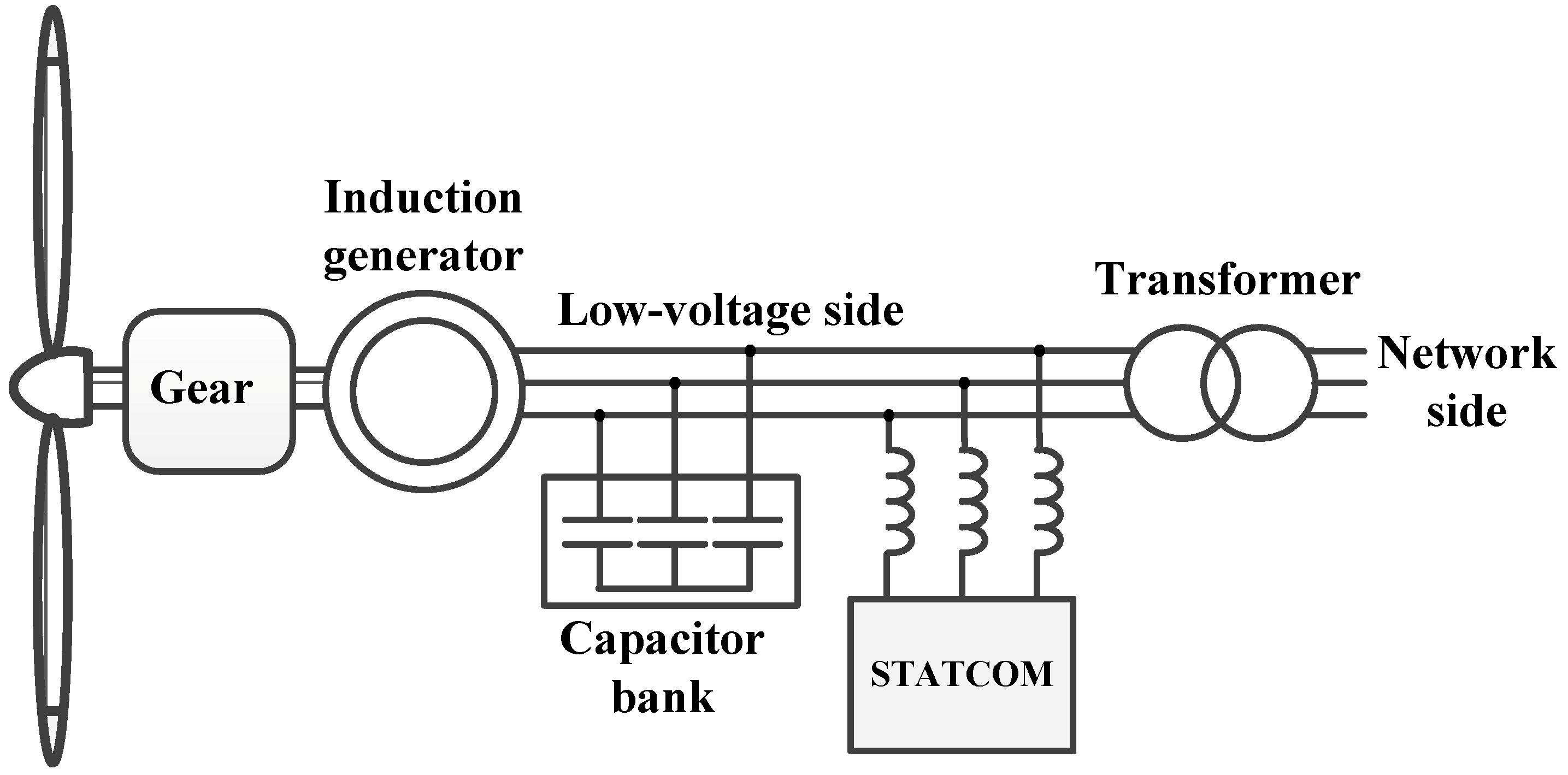
In FSWGs, the induction generator is directly connected to the grid, which makes it difficult for this technology to fulfill almost any grid code requirement. For example, FSWGs are usually disconnected when the voltage drop exceeds 10%–20% with respect to the rated voltage [
12]. Commonly, FSWGs have mechanically switched capacitors to assist them with the power factor; however, for LVRT fulfillment, reactive power compensators, such as static VAR compensators (SVC) and static synchronous compensators (STATCOM) [
9,
13,
14], must be used.
A STATCOM is a reactive power compensator that exhibits a good dynamic response with a high control bandwidth and the capability of providing higher currents at low voltage levels [
12]. It is also desirable to use a STATCOM due to the possibility of working with decoupled control of the DC-link voltage and the reactive current [
15]. However, one of the main drawbacks is the low energy density on the DC link capacitor installed in the STATCOM; this limits the reactive and active power capability of the STATCOM [
16,
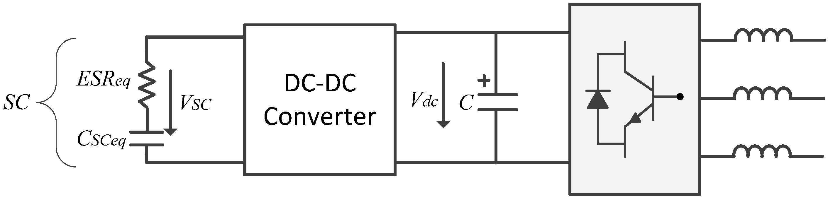
17]. An improved version of the STATCOM is called the STATCOM + ES (energy storage). This variant includes a storage device, usually batteries, supercapacitors (SCs),
etc. The storage device provides more capabilities to the STATCOM, such as power oscillation damping or mitigation of phase-jump-related disturbances [
18,
19,
20,
21,
22,
23,
24]. Moreover, the STATCOM + ES can be used for reactive compensation when an LVRT system is implemented [
25,
26].
The main objective of this paper is to propose a robust and reliable solution that provides FSWG LVRT capability, allowing these types of generators to withstand voltage dips and comply with different grid code requirements. The proposed approach to accomplish this purpose is the use of a STATCOM + ES-based on an SC, which enables not only the fulfillment of the reactive power requirements during a voltage dip, but also the active power requirements,
i.
e., a complete fulfillment of the LVRT conditions can be achieved. The capability of active power generation is implemented by means of an SC and a DC-DC converter in the DC link of the STATCOM [
23,
27]. One of the main features of SCs is their high energy density and large time constants, which makes them very suitable for short-term applications, such as voltage dips, where the disturbances always last less than a second [
21,
28] (see
Appendix 1 for commercially available SCs).
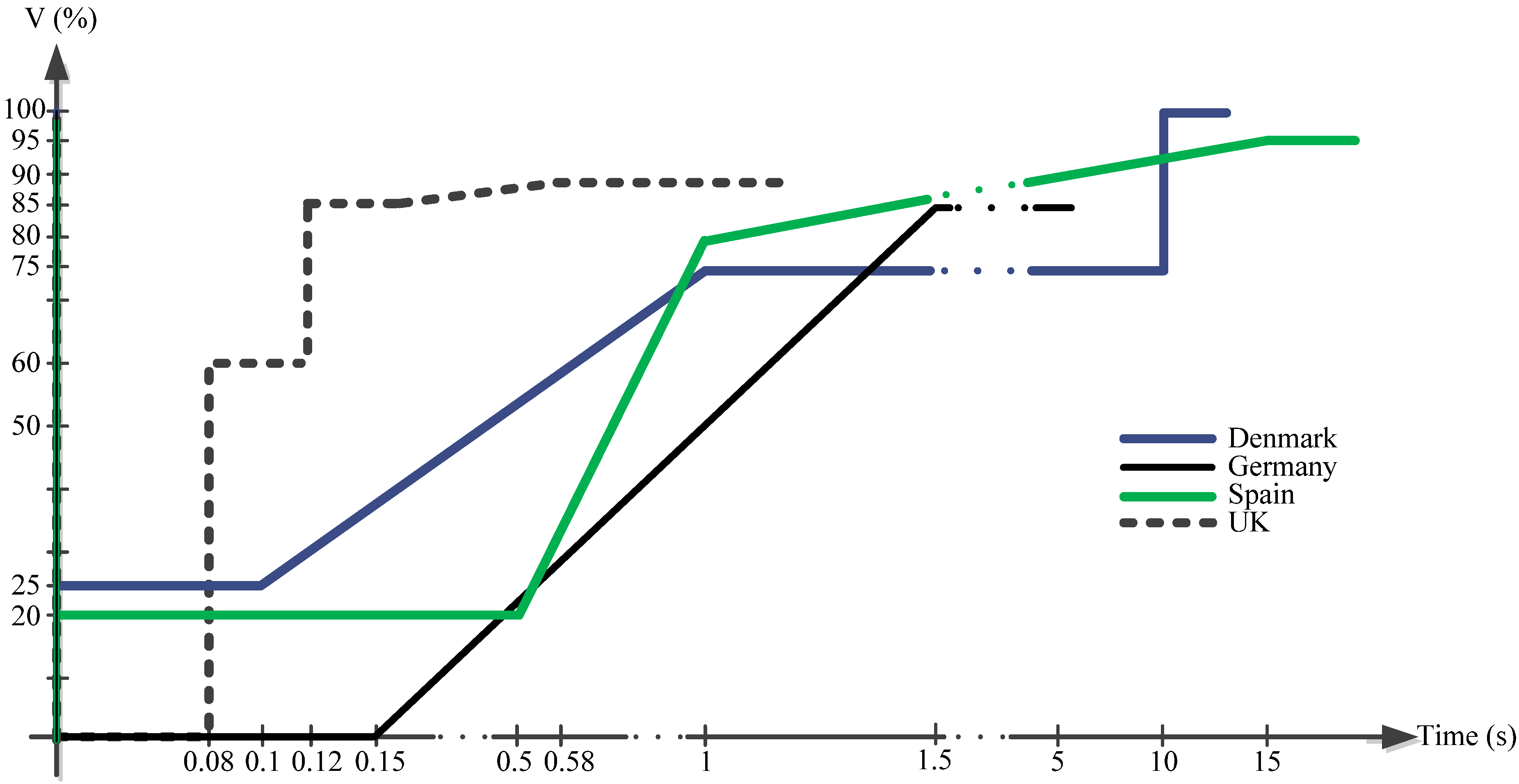
In this study, the grid codes of the following countries are analyzed to establish the LVRT requirements used to define and simulate the compensation system: Denmark, Germany, Spain and the United Kingdom (UK).
The paper is organized as follows.
Section 2 summarizes the LVRT requirements in the grid codes.
Section 3 presents the system model, including the STATCOM description.
Section 4 presents the proposed compensations systems.
Section 5 presents the system control with the decoupled control capability. In
Section 6, the method implemented for the simulations is presented. In
Section 7, the results of all of the simulations are presented, and finally, the conclusions are presented in
Section 8.
5. Control of the Compensation Systems
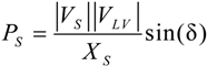
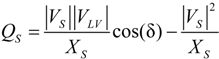
The main objectives of the STATCOM controller with an implemented LVRT strategy are to deliver a determined amount of active and reactive power during a voltage dip. The control scheme is based on a voltage-oriented control applied to three phase converters. In order to establish the inner control structure in a rotating dq reference frame, which allows decoupling of the active and reactive power [
15,
56], it is necessary to analyze the voltage balance across the inductance (
LS) installed at the STATCOM output (see
Figure 9).
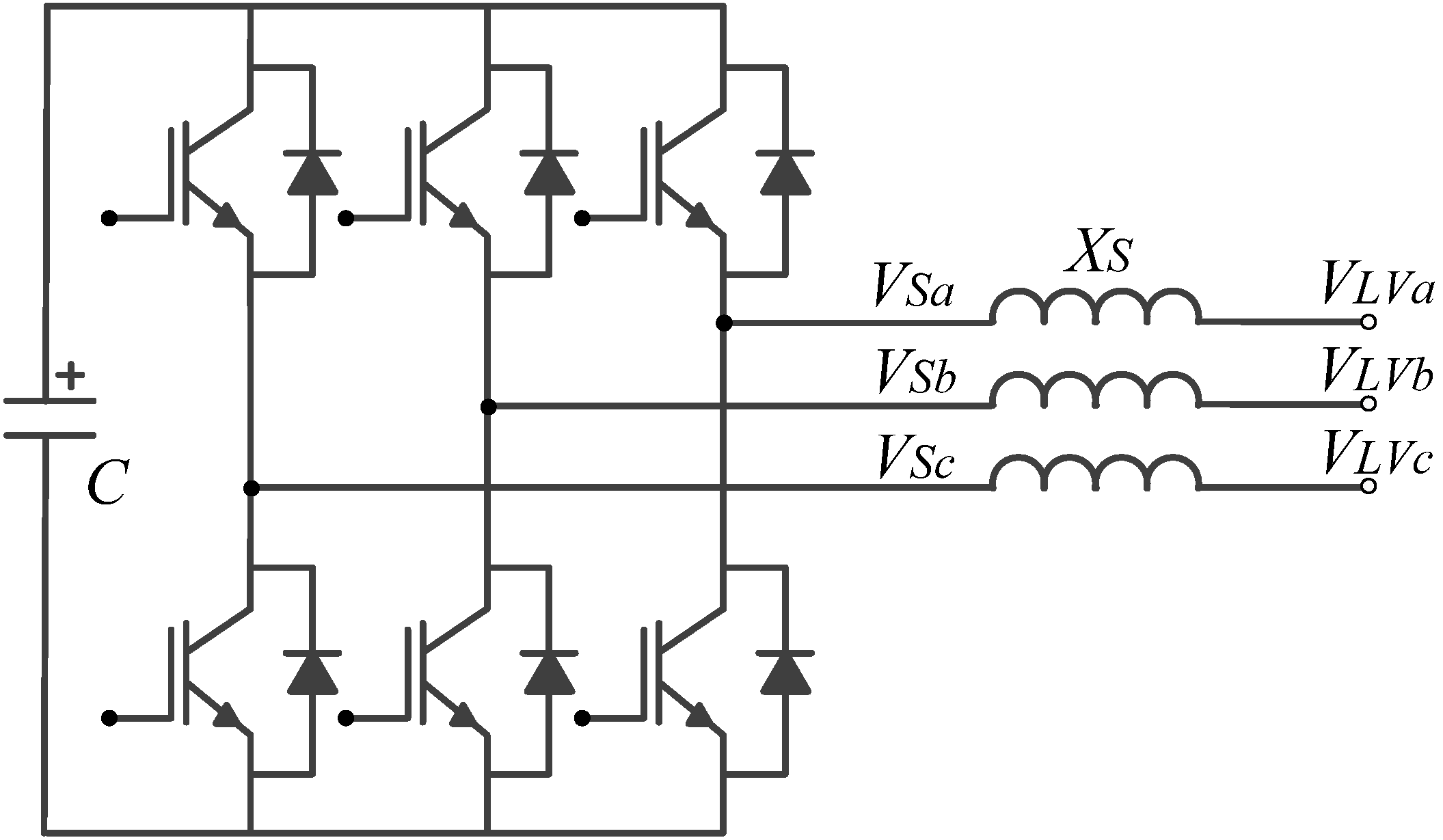
where
VLVa,
VLVb,
VLVc are the three phase components of the WTG low-voltage side voltage;
iSa,
iSb,
iSc are the three phase components of the STATCOM current; and
VSa,
VSb,
VSc are the three phase components of the voltage at the STATCOM terminals.
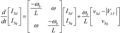
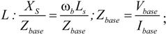
Using Equation (7) and after applying the dq transformation [
57], Equation (8) is obtained:
where:
ωb is the base angular frequency (2π50);
ISd and ISq are the direct and quadrature components of the STATCOM current, respectively;
VSd and VSq are the direct and quadrature components of the STATCOM voltage, respectively;
Vbase and
Ibase are the rated line voltage and nominal current, respectively (see
Table A4 of
Appendix 3);
ω is the reference frame rotating at the grid frequency;
|VLV| is the magnitude of the WTG low-voltage side voltage.
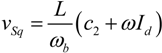
Equation (8), leads to a rule that allows decoupling
ISd and
ISq. The inverter voltage vector is controlled as follows:
where
c1 and
c2 are the proportional plus integral (PI) controllers, defined next.
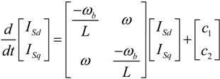
Replacing Equations (9) and (10) in Equation (8), the following equation is obtained:
Equation (11) shows that
ISd and
ISq respond to
c1 and
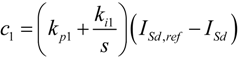
c2, respectively, through a first order transfer function, with no cross-coupling. The control rule for Equations (9) and (10) is completed by defining the feedback loops and PI compensation as follows:
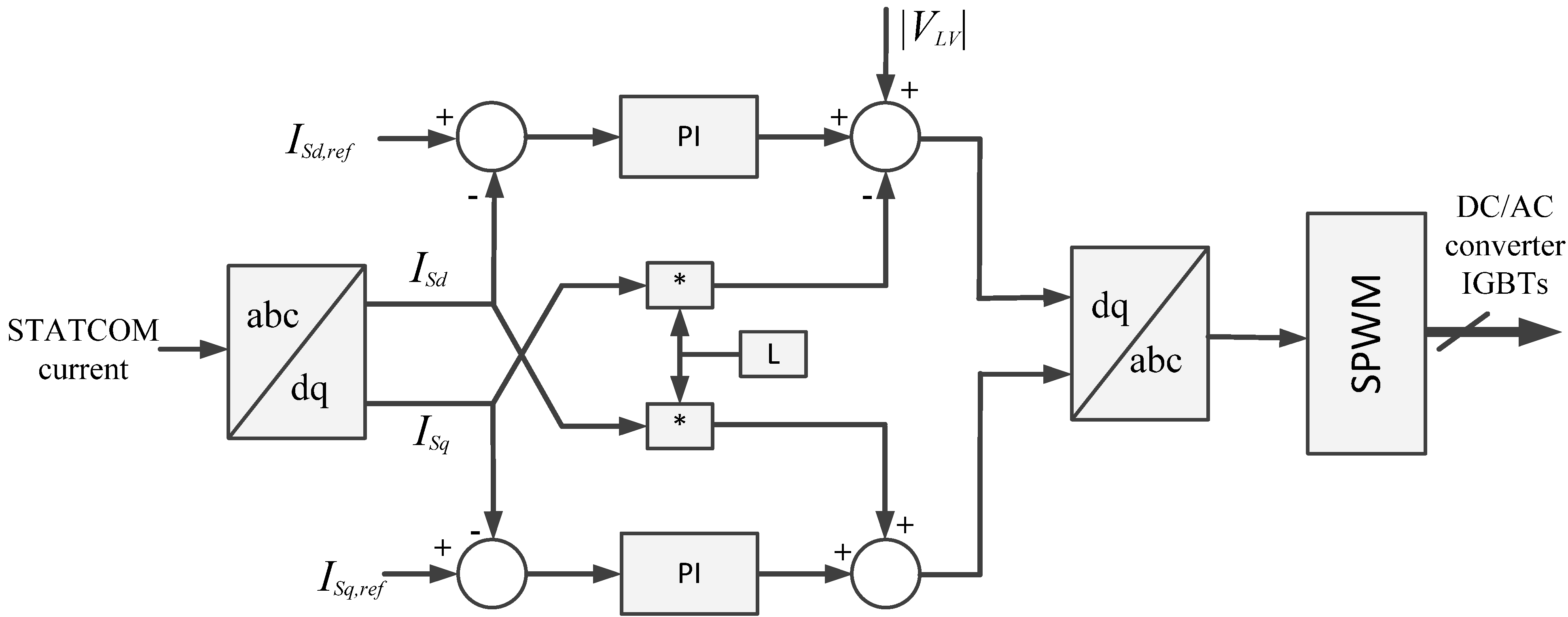
Then, the control system block diagram for the inner control structure is shown in
Figure 13, for which all of the variables are in a dq reference frame after applying the dq transformation [
57]. As a result, the inputs variables are the STATCOM current in dq coordinates (
ISd and
ISq) and the voltage
VLV at the FSWG low-voltage side. The reference variables are those for the STATCOM current,
ISd,ref and
ISq,ref.
Figure 13.
Block diagram of the inner vector control technique implemented in the STATCOM. PI, proportional plus integral.
Figure 13.
Block diagram of the inner vector control technique implemented in the STATCOM. PI, proportional plus integral.
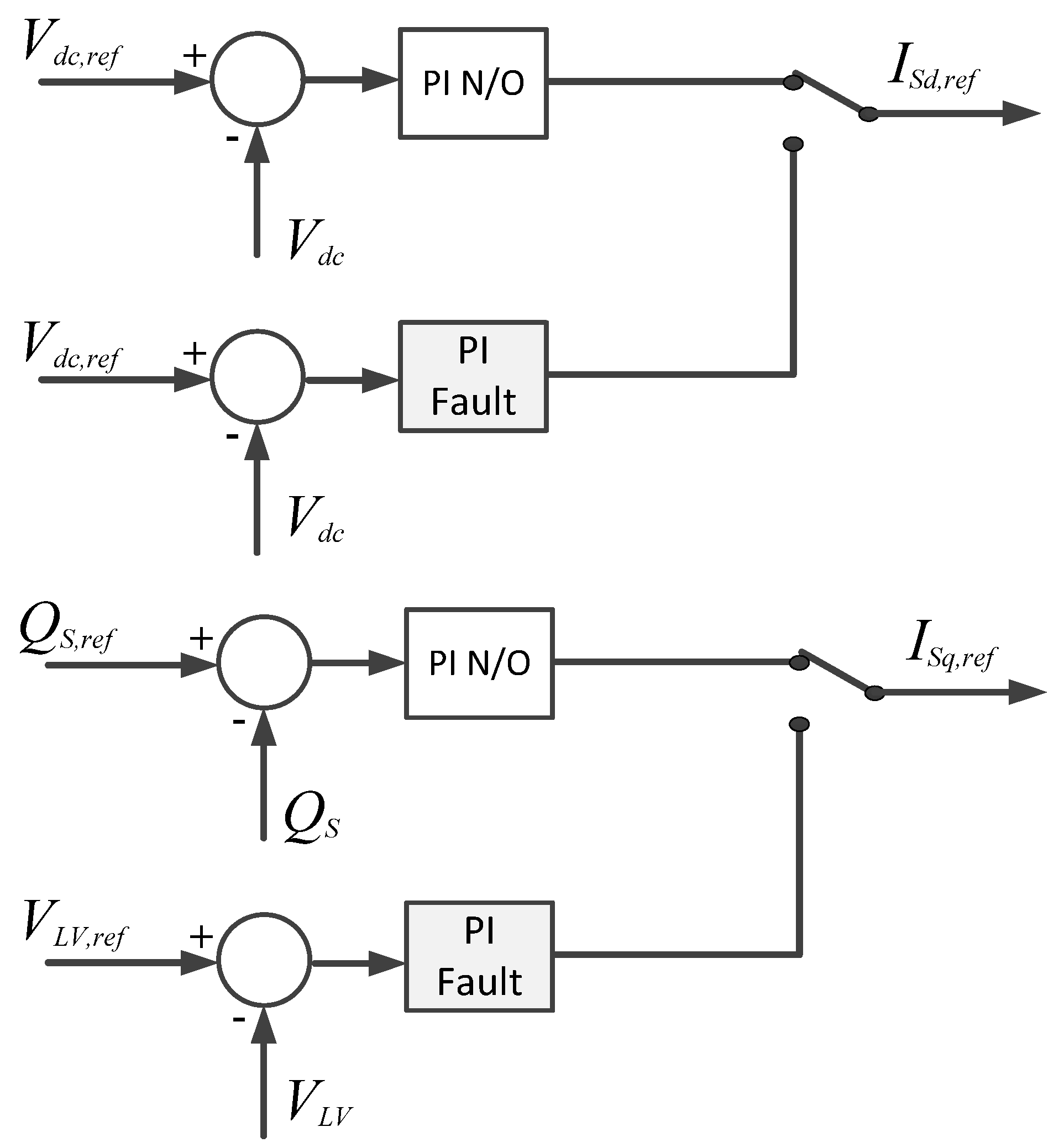
This inner control is set to deliver the voltage references to the SPWM (Sinusoidal Pulse Width Modulation) to fire the IGBTS that control the STATCOM DC/AC converter. The outer control loops are generally designed to maintain the DC voltage to compensate for the converter losses and the voltage at the low-voltage side to control the flow of reactive power between the STATCOM and the power network [
56].
The outer control loops proposed in this paper are a cascade of PIs set to operate under two different situations. When the grid is operating normally, the outer control loop is set to follow the references to maintain the DC link voltage
Vdc at a reference value
Vdc,ref and to control the reactive power injected by the STATCOM,
i.
e.,
Qs and
Qs,ref (see the N/O blocks in
Figure 14). However, when the grid is under the fault condition, the direct axis outer control loop is set to maintain the DC link voltage at a constant level through a faster PI, and the quadrature outer control loop is set to maintain the rated low-voltage side voltage
VLV,ref (see fault blocks in
Figure 14). The outer control structure is shown in
Figure 14. The target of these separate controllers is to provide adequate references to the inner control loop to deliver the necessary amount of active and reactive power to back up the FWSG under a voltage dip. Note that the overall control structure is achieved by combining the blocks shown in
Figure 13 and
Figure 14.
Figure 14.
Block diagram of the outer control technique implemented in the STATCOM. (N/O = normal operation, Fault = fault condition).
Figure 14.
Block diagram of the outer control technique implemented in the STATCOM. (N/O = normal operation, Fault = fault condition).
Recall that the main objective of this paper is to explore the capabilities of a STATCOM with SCs in its DC side. To enable this exploration, classical PI controllers are chosen here.
6. Simulations Scenarios
In this section, the simulation results of the operation of the FSWG with and without the compensation of the STATCOM under voltage dips and the requirements of the grid codes of Denmark, Germany, Spain and the UK are presented and discussed.
Four different LVRT requirements are simulated under the following scenarios:
FSWG: FSWG in its standard configuration, i.e., directly connected to the grid. In this case, the capacitor bank of the WTG, commonly used for power factor correction, is disconnected;
FSWG + STATCOM: FSWG with a shunt-connected STATCOM for reactive and LVRT purposes;
FSWG + STATCOM + ES: FSWG with a STATCOM + ES that includes an SC in the DC link;
FSWG + STATCOM + ES + (DC/DC): FSWG with a STATCOM + ES with the SC connected through a DC-DC converter.
In total, 20 simulations are performed to study the behavior of the FSWG under different LVRT requirements. All simulations were performed with the WTG running at its rated power.
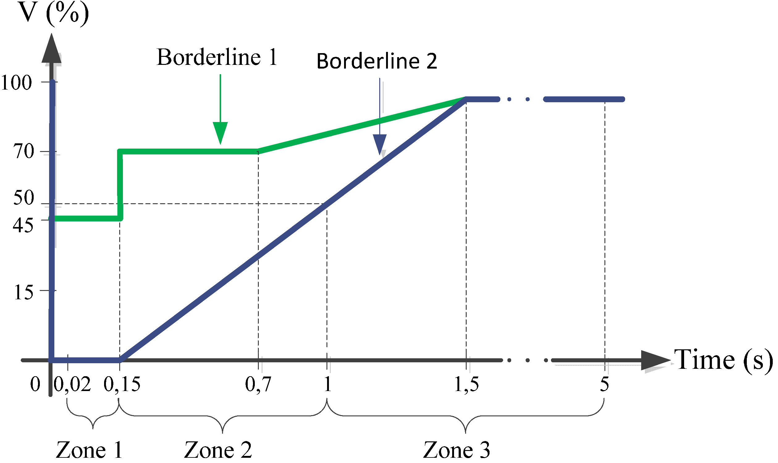
Note that, unlike the other grid codes, the Spanish grid code demands that WTGs must withstand the profile shown in
Figure 4 during a test, or if a simulation test is performed, the system must be simulated using the equivalent electrical grid described in the PVVC [
31]. For this reason, it was necessary to perform two simulations, the first one using the equivalent electrical grid, in which a three-phase fault that lasts 150 ms was simulated, and the second one implemented according to the profile presented in the P.O. 12.3 shown in
Figure 4.
To simulate the voltage dips, a three-phase fault is introduced according to the profile of each grid code. The operation of the system without the capacitor bank and STATCOM compensation (Scenario 1) is simulated to represent the worst scenario. Scenarios 2, 3 and 4 are performed with a shunt STATCOM connected; in this case, the objectives of the STATCOM controller during normal operation are to achieve zero reactive power injection at the PCC and to maintain the voltage in the DC link at its rated value. The target during a voltage dip is to fulfill the LVRT requirements and, in a generic way, to minimize the voltage variations in the DC link.
As an example, for the sake of simplicity and because the German requirements appear to be the most demanding ones, the response of the FSWG under the German’s SO requirements are shown in
Figure 15. Note that the simulations are divided into zones, as explained in
Table 2. In
Section 7, the results for the remaining simulations are summarized.
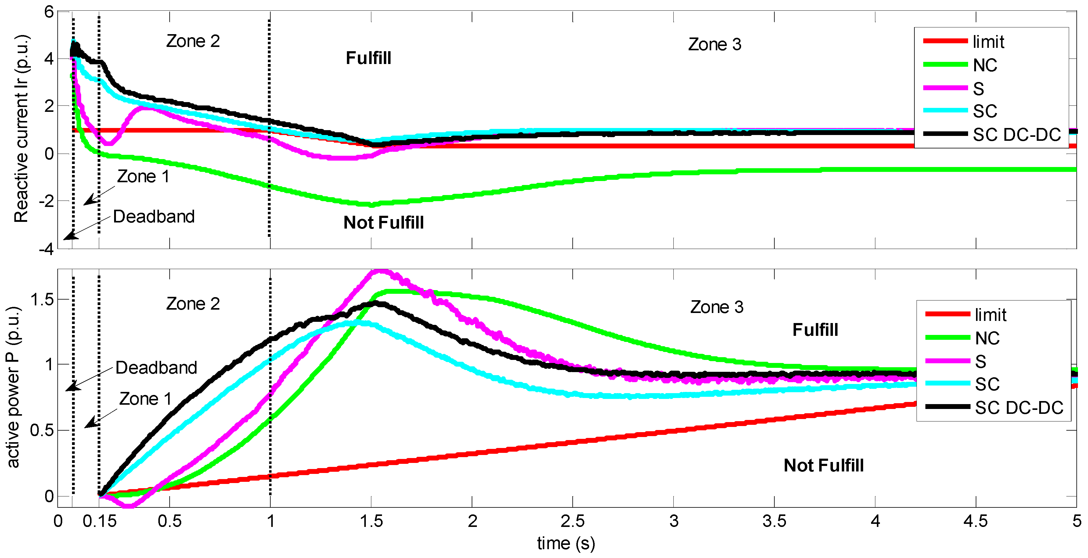
Figure 15.
WTG response under German LVRT requirements. NC, results without a STATCOM; S, results with a STATCOM; SC, results with a STATCOM + ES (SC in the DC link); SC DC-DC, results with a STATCOM + ES and a DC-DC converter in the DC link.
Figure 15.
WTG response under German LVRT requirements. NC, results without a STATCOM; S, results with a STATCOM; SC, results with a STATCOM + ES (SC in the DC link); SC DC-DC, results with a STATCOM + ES and a DC-DC converter in the DC link.
The following nomenclature is used in the following figures:
Lim: Limit of the variable, active power P or reactive current Ir;
NC: results without a STATCOM;
S: results with a STATCOM;
SC: results with a STATCOM + ES (SC in the DC link);
SC DC-DC: results with a STATCOM + ES and a DC-DC converter in the DC link.
The worst possible scenario is depicted with the NC label, as shown in
Figure 15. The sudden reduction of the voltage in the grid leads to an important reactive current consumption in the PCC. As shown in the figure, this requirement is not being fulfilled in any of the marked zones of the German grid code. This behavior could lead to an overall instability and cause the disconnection of the WTG, which is currently an unacceptable performance of any WTG according to grid codes.
The next scenario is simulated with the same grid fault, but in this case, the WTG is supported by a STATCOM. In this case, as previously explained, the STATCOM is controlled to compensate for the reactive power in the grid. When the control senses the fault, the STATCOM starts injecting reactive current into the grid to comply with the grid codes (see
Figure 15). Note that, in this scenario, the reactive current requirement is close to that demanded in the code. The clear drawback of this possible solution is that the FSWG is not able to fulfill the grid codes. It is important to notice that, in this case, the active power requirement in Zone 2 is not being fulfilled, because of the lack of the STATCOM’s capability of active power generation.
Next, following the same procedure, the grid fault is introduced, but this time, the FSWG is being supported by a STATCOM + ES. This variant was set up to fully comply with the German grid code. The important difference in this case is that, as a result of a larger storage device,
i.
e., an SC, the WTG is now able to deliver the required amount of reactive current and is also able to deliver the required active power demanded in Zone 2, as shown in
Figure 15.
Finally, after noting the advantages of including a higher storage device in the DC link of the STATCOM, a shunt DC-DC converter was installed in the DC link of the STATCOM + ES to enable control of the SC discharge, thereby supplying more active power to the grid. As a result, when the STATCOM + ES with a DC-DC converter is supporting the FSWG under voltage dips, it was also possible to comply with the grid codes, but this time with an improved active power response, as shown in
Figure 15.
To enhance the understanding of and to provide an indication of the influence in the grid of the STATCOM + ES with the DC-DC converter with respect to the STATCOM and STATCOM + ES, in
Figure 16,
Figure 17,
Figure 18,
Figure 19 and
Figure 20, the evolution during the voltage dip of the most important variables are shown.
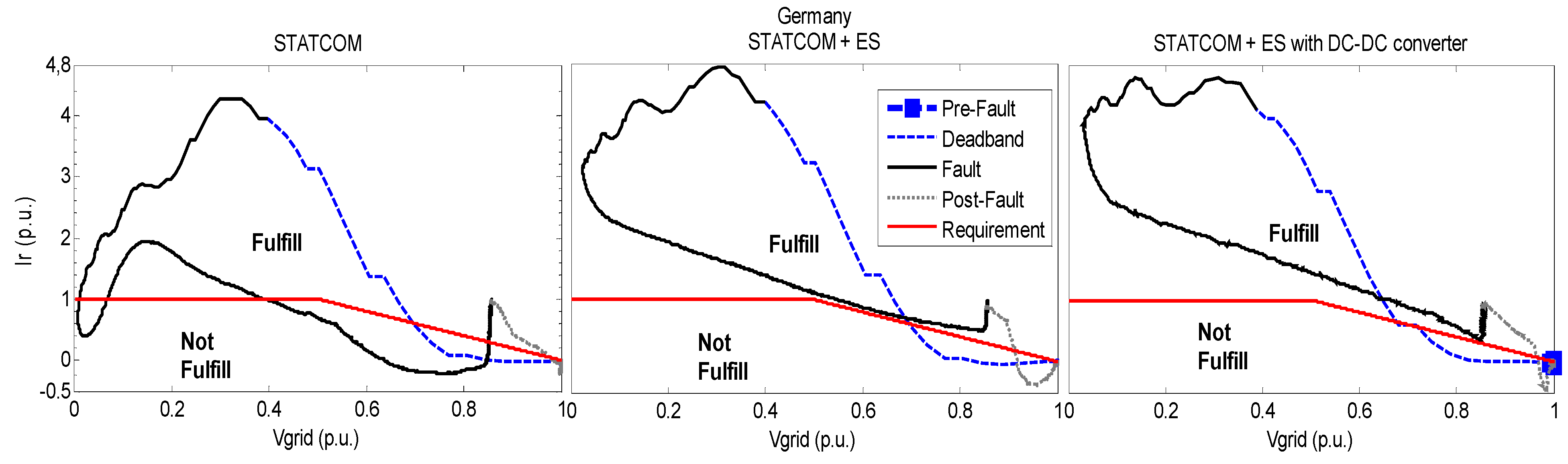
Figure 16.
Reactive current evolution through the voltage dip, German case.
Figure 16.
Reactive current evolution through the voltage dip, German case.
The evolution of the reactive current in the grid
, before, during and after the fault is shown in
Figure 16. The solid black line corresponds to the reactive current behavior in the analysis zones, and the red one corresponds to the requirements. Note that the reactive current requirement is being fulfilled by means of the STATCOM + ES and STATCOM + ES with the DC-DC converter.
Figure 17.
Active power evolution through the voltage dip, German case.
Figure 17.
Active power evolution through the voltage dip, German case.
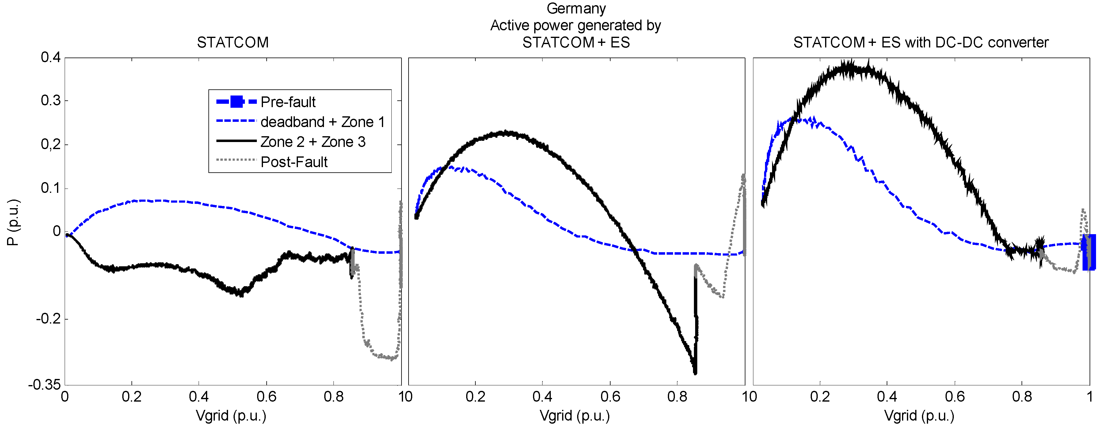
Figure 18.
STATCOM active power evolution through the voltage dip, German case.
Figure 18.
STATCOM active power evolution through the voltage dip, German case.
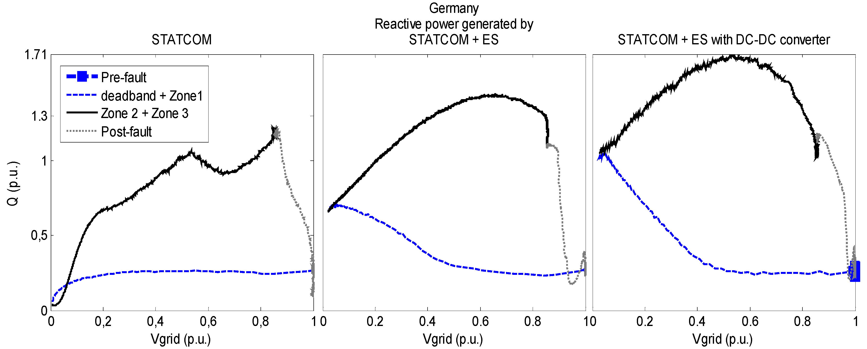
Figure 19.
STATCOM reactive power evolution through the voltage dip, German case.
Figure 19.
STATCOM reactive power evolution through the voltage dip, German case.
Figure 20.
DC link voltage and DC-DC converter voltage in the SC during voltage dip, German case.
Figure 20.
DC link voltage and DC-DC converter voltage in the SC during voltage dip, German case.
Similarly, in
Figure 17, the active power evolution and requirements in the German grid code are shown. Here, a clear active power enhancement of the active power response in the grid is observed. Once again, the solid black line corresponds to the active power behavior in the analysis zones, and the red line corresponds to the requirement.
The active and reactive power injection responses for the different configurations (STATCOM, STATCOM + ES and STATCOM + ES with DC-DC converter) are shown in
Figure 18 and
Figure 19. In
Figure 18, the improvement achieved by means of the inclusion of a supercapacitor in the DC link is observed. Finally, in
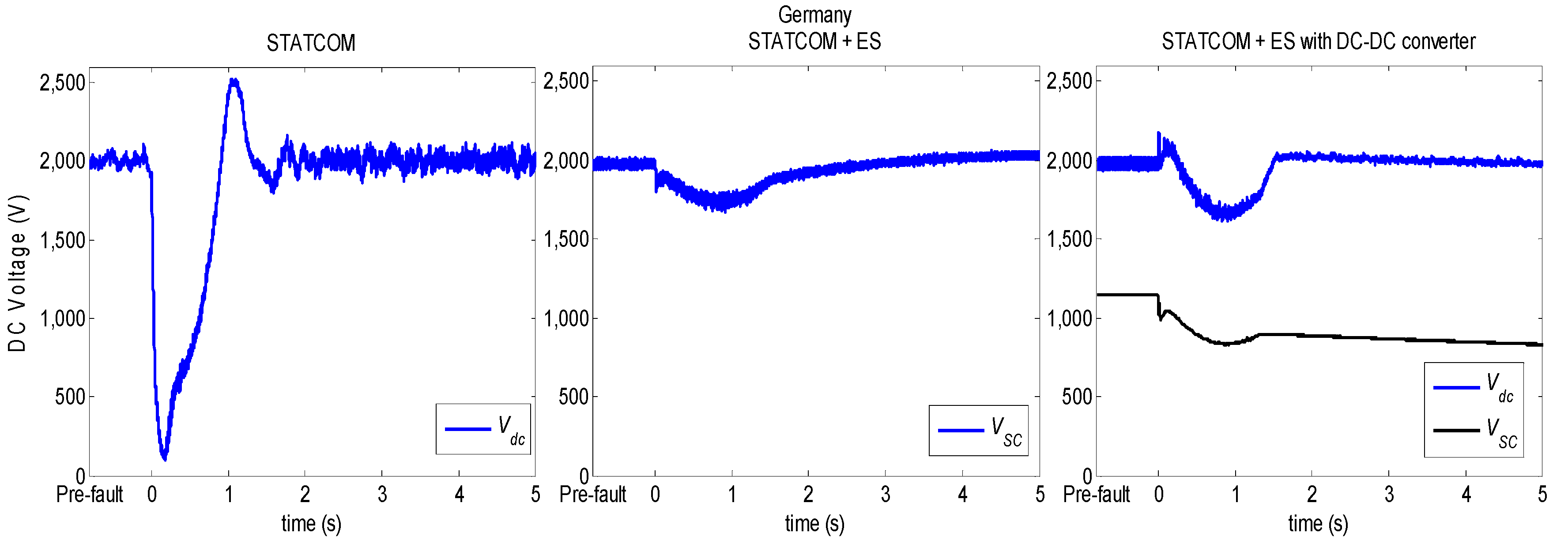
Figure 20 is shown the evolution of the voltage in the DC link and the SC during the voltage dip.
7. Summary of Results
In
Section 6, the behavior of the FSWG under the requirements of the German’s SO was presented. To simplify the analysis and summarize the results, in
Table 3 and
Table 4 present the results of the previous section. The minimum result obtained in each zone per simulation and its corresponding requirement are presented. The tables are divided per country and per zone; in each box is presented the requirement in brackets and above it, the result. The zones without requirement are denoted as not available (N/A). Finally, green values denote fulfillment and red values are those where the specific requirement is not fulfilled.
The results for the FSWG simulation in the worst case scenario are presented in
Table 3, which summarizes the behavior of the FSWG during the voltage dip without the capacitor bank. In this case, the WTG is unable to fulfill almost any of the reactive current requirements; therefore, this appears to be the most demanding requirement.
The results for the simulation of the FSWG with the shunt STATCOM, STATCOM + ES and STATCOM + ES with DC-DC are summarized in
Table 3 and
Table 4. With only the STATCOM contribution, the requirements of the Danish and Spanish grid codes are fulfilled (see
Table 3). The UK’s requirements are not fulfilled during the first 10 ms of the fault, because the UK’s grid code demands that the generation units shall inject the maximum reactive current during the fault without a deadband, which is allowed by the other grid codes (e.g., the German grid code demands that the WTG must respond to the reactive current requirement within 20 ms [
3]). Note that with a proper deadband, it would be possible to fulfill all of the UK’s requirements with the addition of a STATCOM alone.
Table 3.
Results and requirements, in p.u., of the different grid codes, without a capacitor bank and with a STATCOM. Requirements are shown in brackets, red values are those where the specific requirement is not fulfilled and N/A means not available. PVVC, procedure for verification and validations.
| Country | Denmark | Germany | Spain | UK |
|---|
| PVVC | P.O. 12.3 |
|---|
| Zone | 1 | 2 | 1 | 2 | 3 | 1 | 2 | 3 | 1 | 2 | 3 | 1 | 2 |
|---|
| Without capacitor bank | Active power | 0.128 | 0.118 | N/A | −3.72×10⁻⁶ | 0.577 | N/A | 0.069 | N/A | N/A | 0.064 | N/A | N/A | 1.001 |
| (0.101) | (0.101) | (0.00017) | (0.148) | (0.1) | (0.1) | (0.9) |
| Reactive current | −0.588 | −1.782 | 0.061 | −1.381 | −2.166 | N/A | −0.563 | −2.468 | N/A | 0.626 | −0.747 | −0.588 | N/A |
| (−1.0) | (−1.0) | (1.0) | (1.0) | (0.30378) | (0.015) | (−1.5) | (0.015) | (−1.5) | (1.0) |
| Reactive power | N/A | N/A | N/A | N/A | N/A | −0.582 | −0.049 | N/A | −0.583 | −0.063 | N/A | N/A | N/A |
| (−0.6) | (0) | (−0.6) | (0) |
| Reactive energy | N/A | N/A | N/A | N/A | N/A | N/A | N/A | −1.058 | N/A | N/A | −0.153 | N/A | N/A |
| (−0.6) | (−0.6) |
| STATCOM | Active power | 0.165 | 0.161 | N/A | −0.0834 | 0.766 | N/A | −0.067 | N/A | N/A | 0.057 | N/A | N/A | 1.001 |
| (0.101) | (0.101) | (0.00017) | (0.148) | (0.1) | (0.1) | (0.9) |
| Reactive current | −0.014 | −0.595 | 0.741 | 0.394 | −0.217 | N/A | 0.807 | −1.213 | N/A | 0.416 | −0.375 | −0.015 | N/A |
| (−1.0) | (−1.0) | (1.0) | (1.0) | (0.30378) | (0.015) | (−1.5) | (0.015) | (−1.5) | (1.0) |
| Reactive power | N/A | N/A | N/A | N/A | N/A | −0.015 | 0.138 | N/A | −0.018 | 0.0498 | N/A | N/A | N/A |
| (−0.6) | (0) | (−0.6) | (0) |
| Reactive energy | N/A | N/A | N/A | N/A | N/A | N/A | N/A | −0.336 | N/A | N/A | −0.036 | N/A | N/A |
| (−0.6) | (−0.6) |
Table 4.
Results and requirements, in p.u., of the different grid codes, with a STATCOM + ES and with a STATCOM + ES with DC-DC converter. Requirements are shown into brackets, red values are those where the specific requirement is not fulfilled and N/A means not available.
Table 4.
Results and requirements, in p.u., of the different grid codes, with a STATCOM + ES and with a STATCOM + ES with DC-DC converter. Requirements are shown into brackets, red values are those where the specific requirement is not fulfilled and N/A means not available.
| Country | Denmark | Germany | Spain | UK |
|---|
| PVVC | P.O. 12.3 |
|---|
| Zone | 1 | 2 | 1 | 2 | 3 | 1 | 2 | 3 | 1 | 2 | 3 | 1 | 2 |
|---|
| STATCOM + ES | Active power | 0.172 | 0.153 | N/A | 0.004 | 0.747 | N/A | 0.031 | N/A | N/A | 0.091 | N/A | N/A | 0.988 |
| (0.101) | (0.101) | (0.00017) | (0.148) | (0.1) | (0.1) | (0.9) |
| Reactive current | −0.018 | −0.319 | 3.092 | 1.043 | 0.492 | N/A | 0.877 | −0.779 | N/A | 0.507 | 0.144 | −0.02 | N/A |
| (−1.0) | (−1.0) | (1.0) | (1.0) | (0.30378) | (0.015) | (−1.5) | (0.015) | (−1.5) | (1.0) |
| Reactive power | N/A | N/A | N/A | N/A | N/A | −0.019 | 0.298 | N/A | −0.019 | 0.061 | N/A | N/A | N/A |
| (−0.6) | (0) | (−0.6) | (0) |
| Reactive energy | N/A | N/A | N/A | N/A | N/A | N/A | N/A | −0.211 | N/A | N/A | 0.082 | N/A | N/A |
| (−0.6) | (−0.6) |
| STATCOM + ES with DC−DC converter | Active power | 0.297 | 0.421 | N/A | 0.006 | 0.906 | N/A | −0.201 | N/A | N/A | 0.379 | N/A | N/A | 0.966 |
| (0.101) | (0.101) | (0.00017) | (0.148) | (0.1) | (0.1) | (0.9) |
| Reactive current | −0.021 | −0.395 | 3.859 | 1.375 | 0.359 | N/A | 0.667 | −1.046 | N/A | 0.491 | 0.64 | −0.01 | N/A |
| (−1.0) | (−1.0) | (1.0) | (1.0) | (0.30378) | (0.015) | (−1.5) | (0.015) | (−1.5) | (1.0) |
| Reactive power | N/A | N/A | N/A | N/A | N/A | −0.057 | 0.304 | N/A | −0.034 | 0.217 | N/A | N/A | N/A |
| (−0.6) | (0) | (−0.6) | (0) |
| Reactive energy | N/A | N/A | N/A | N/A | N/A | N/A | N/A | −0.306 | N/A | N/A | 0.228 | N/A | N/A |
| (−0.6) | (−0.6) |
In the German case, the requirements in Zones 1, 2 and 3 require the generator to deliver more reactive current; with the use of a STATCOM alone, it was not possible to deliver the maximum reactive current (note that the maximum reactive current generation in the German’s grid code is only by the request of the SO). Note that the active power generation during a voltage dip becomes an issue because of the low capability of the STATCOM to inject active power into the grid. This requirement and the reactive current requirement were fulfilled using an SC in the STATCOM’s DC link, as found in
Table 4. Moreover, it was also possible to deliver as much active power as requested in the German grid code using the STATCOM + ES with the bidirectional DC-DC converter; although the simulations results with the SC in the DC link and the DC-DC converter seem to be quite similar, it was possible to deliver more active power with the addition of the DC-DC converter. However, the UK’s grid code still has the same deadband issue; with the SC, the generation of reactive current starts at 5 ms, and the maximum reactive current is reached at 9 ms.
Finally, one of the most important achievements can be seen in
Figure 15 and
Figure 18, where the SC is placed in the low voltage side of the DC-DC converter (STATCOM + ES + DC/DC); in this case, the STATCOM was able to deliver more active power than in the other approaches.
8. Conclusions
The first part of this paper presented the analysis of the LVRT requirements in the grid codes for a set of countries that represent the worldwide trends in wind energy. The more demanding codes appear to be the German and the UK codes, because they demand that the WTG has to withstand a fault down to zero volts in the PCC, and they do not allow any reactive consumption during the voltage dip.
Next, the methods that enable the FSWGs to fulfill the LVRT requirements of the grid codes were analyzed. This type of WTG was selected for two reasons: it has an important presence in the countries where wind energy was first developed, and this type of machine cannot fulfill the LVRT requirements by itself, as seen in
Table 3. Therefore, this paper presented a system based on a STATCOM installed at the low-voltage side of an FSWG that enables these types of wind generators to fulfill the LVRT requirements. The simulation results indicate that, by means of the proposed configuration, it is possible to fulfill the LVRT requirements of the Spanish and the Danish grid codes. However, for the German case, due to the active power demands, it is proposed to introduce an energy storage device in the DC link, resulting in the STATCOM + ES configuration. In this paper, the use of supercapacitors was proposed for that purpose. The UK’s grid code was not satisfied, due to the lack of a deadband that would allow the power electronics to react in time. Note that this code could be fulfilled with only the use of a STATCOM alone if a minimum deadband is considered.
Finally, the inclusion of a DC-DC converter in the DC link of the STATCOM and the supercapacitor in the low voltage side of the converter is proposed; it was possible to deliver a considerable amount of active power into the grid during the fault and restoration of the voltage. This configuration allows control of the power flow between the SC and the grid, because the bidirectional converter provides the possibility to control the discharge of the SC without interfering with the DC link voltage of the STATCOM. By means of this configuration, deeper discharge levels at the SC side are achievable; therefore, more active power could be delivered to the grid without interfering with the reactive power injection. For example, with the use of the STATCOM + ES, 4% more active power is generated than with the STATCOM alone, and with the STATCOM + ES with the DC-DC converter (Danish simulation, Zone 1), 80% more active power is generated than with the STATCOM alone. This feature of the STATCOM + ES could be further exploited for inertia emulation, to smooth the active power output of the STATCOM, to maintain the DC link voltage as relatively constant or for frequency response.
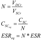
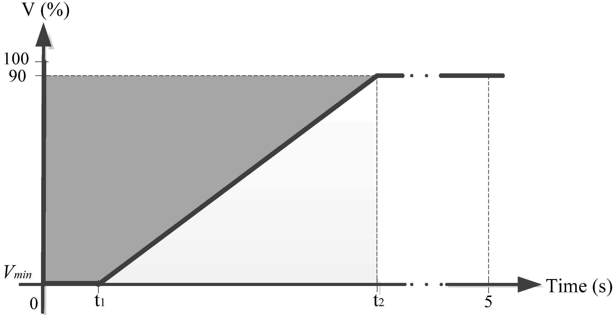
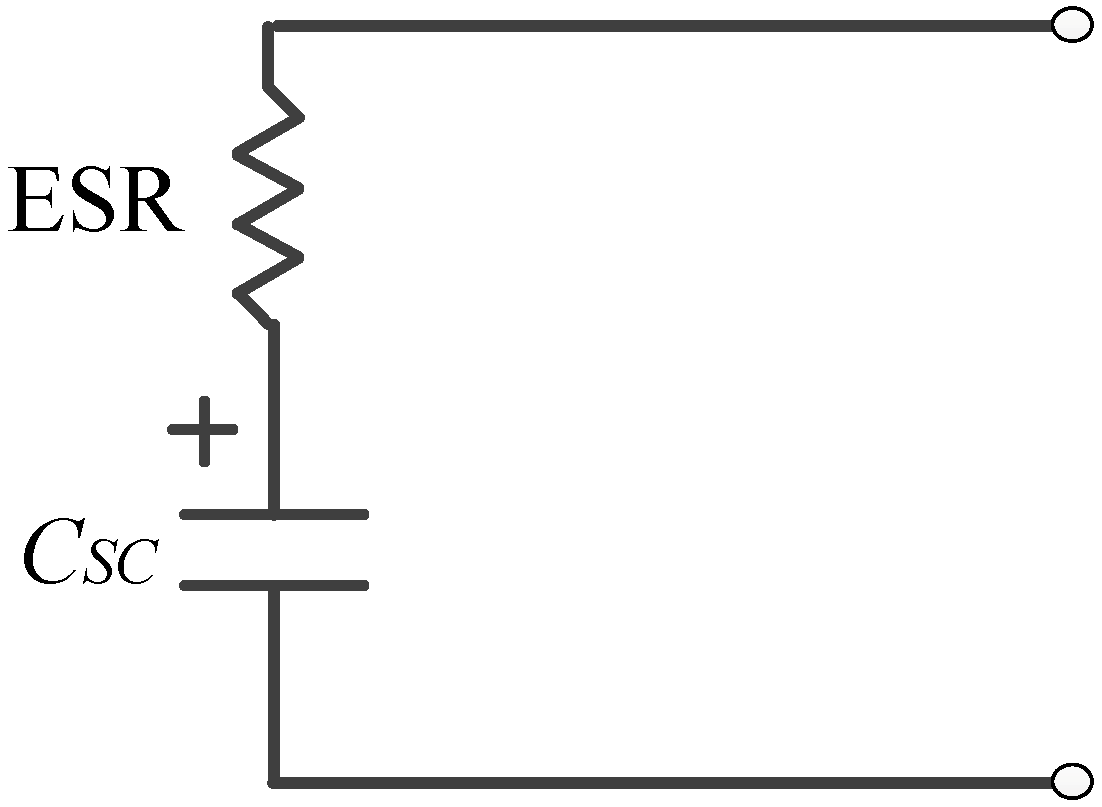
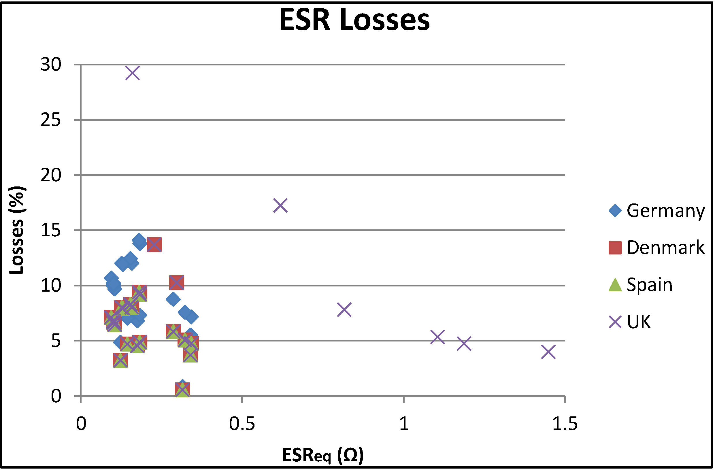
A method for calculating the required capacitance of the SC during a voltage dip is also suggested. The influence of the power losses in the ESR and the minimum achievable SOC was taken into account to provide the STATCOM the possibility to deliver the energy required by each of the grid codes investigated.


