Research on the Power Management Strategy of Hybrid Electric Vehicles Based on Electric Variable Transmissions

Abstract
: Electric variable transmission is a new electromechanical energy conversion device structure, which is especially suitable as the driving force distribution device for hybrid electric vehicles. This paper focuses on the power management strategy of hybrid electric vehicles based on an electric variable transmission, and a kind of hierarchical control ideology is proposed. The control strategy is composed of four control levels, namely analysis of force requirement, operation mode switching, force distribution and coordinate control, which are designed respectively in this paper. Then a simulation model is built based on the notion of energetic macroscopic representation, and an experimental test bench is built. The simulation and experiment results demonstrate the feasibility of the proposed strategy, and it can be taken as a new theory and method for the study of hybrid electric vehicle based on electric variable transmission.1. Introduction
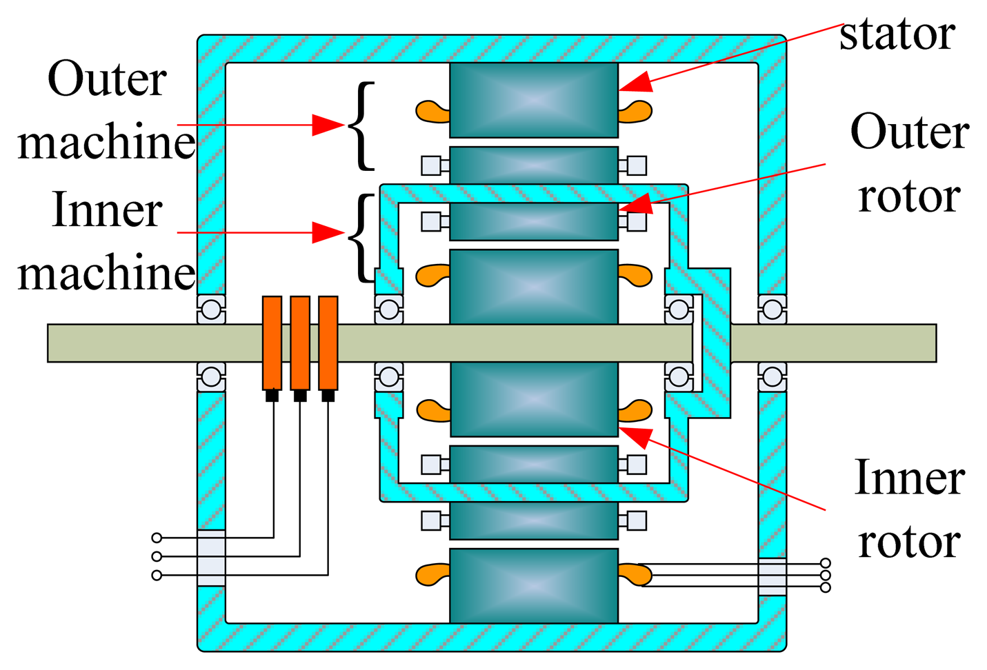
Electric variable transmission (EVT) is a new electromechanical energy conversion device structure, shown in Figure 1. The EVT with double rotor structure has the advantages of fast response, high acceleration, strong overload capacity, and high mechanical integration. EVT can take advantage of machines' space and volume to improve their performance in the case of restricted working conditions [1,2]. EVT is especially suitable as the driving force distribution device for hybrid electric vehicles (HEVs) [3]. Theoretical analysis has showed that EVT can take the place of the planetary gear in the Prius series HEV, implementing the functions of the internal combustion engine (ICE) idling stop, force compensation and braking energy regeneration [4,5], so EVT has broad application prospects in the HEV field.
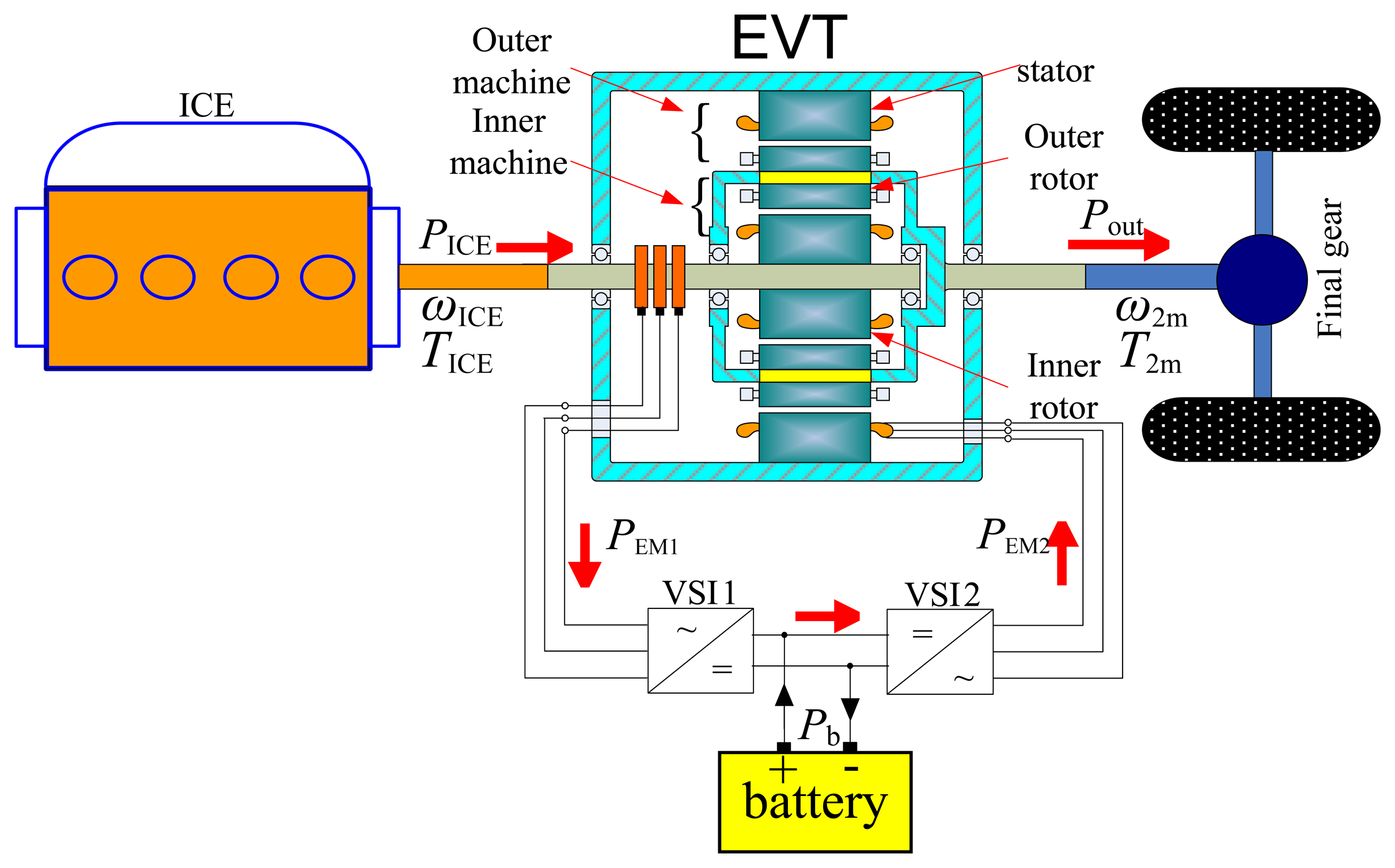
The system structure of an HEV based on EVT is shown in Figure 2. The inner rotor of the EVT is connected to the crankshaft of the ICE mechanically, and the outer rotor is connected to the final gear.
The control system of a HEV based on EVT is in the theoretical research stage. Researchers have mainly focused on magnetic flux coupling analysis, motor design, parameter matching, and operation mode analysis [6–9], which set a foundation for practical application. However, there are a lot of problems to be further studied. The research of this paper mainly focuses on the power management strategy of a EVT-based HEV. The power management strategy research of HEVs based on EVT includes not only vehicle dynamic properties, fuel economy and driving comfort, but also operation mode switching and force distribution, which is more complex than that of a traditional hybrid system. For analyzing and formulating the control strategy clearly, a kind of hierarchical control ideology of HEV is proposed. The vehicle control strategy is decomposed into four levels, which are analysis of force requirement, operation mode switching, force distribution and coordinate control, respectively.
2. Simulation Modeling of an EVT-Based HEV
In order to investigate the power management strategy, the inverse simulation model of HEV based on EVT is set up firstly, with the opposite direction of power output. According to requirement of driving cycle, the energy transfer process and output references of power trains are derived without the driver model [10].
To clearly express the energy flows in this complex system and provide a reference to the system control scheme design, the ideology of energetic macroscopic representation (EMR) is introduced to analyze and build the EVT-based HEV model. Introduced in 2000, EMR was proposed by Bouscayrol from the perspective of the energy flows, according to the principle of action and reaction [11]. The EMR method model is built with graphical symbols, and the graphical symbols in the EMR method are shown in the Table 1.
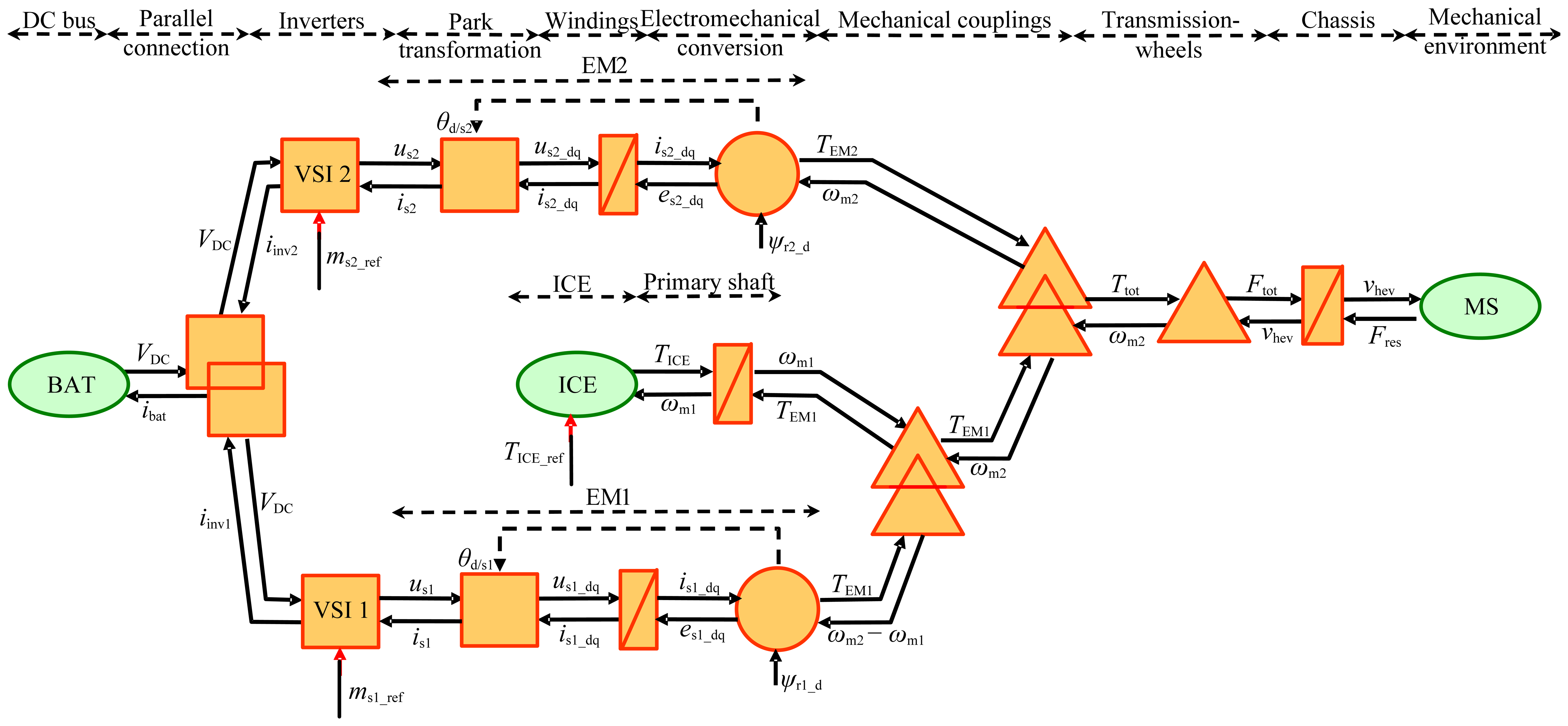
EMR is used to describe the complex electromechanical systems, such as HEV systems, wind power systems, etc. The energy flows are much clearer in the EMR model, and the control scheme is easier to achieve. The EMR simulation method consists of two parts. The first part is the physical prototype model, and the other part is the inversion control model. The physical prototype model of a HEV based on EVT is shown in Figure 3. The inner machine is defined as EM1, and the outer machine is defined as EM2.
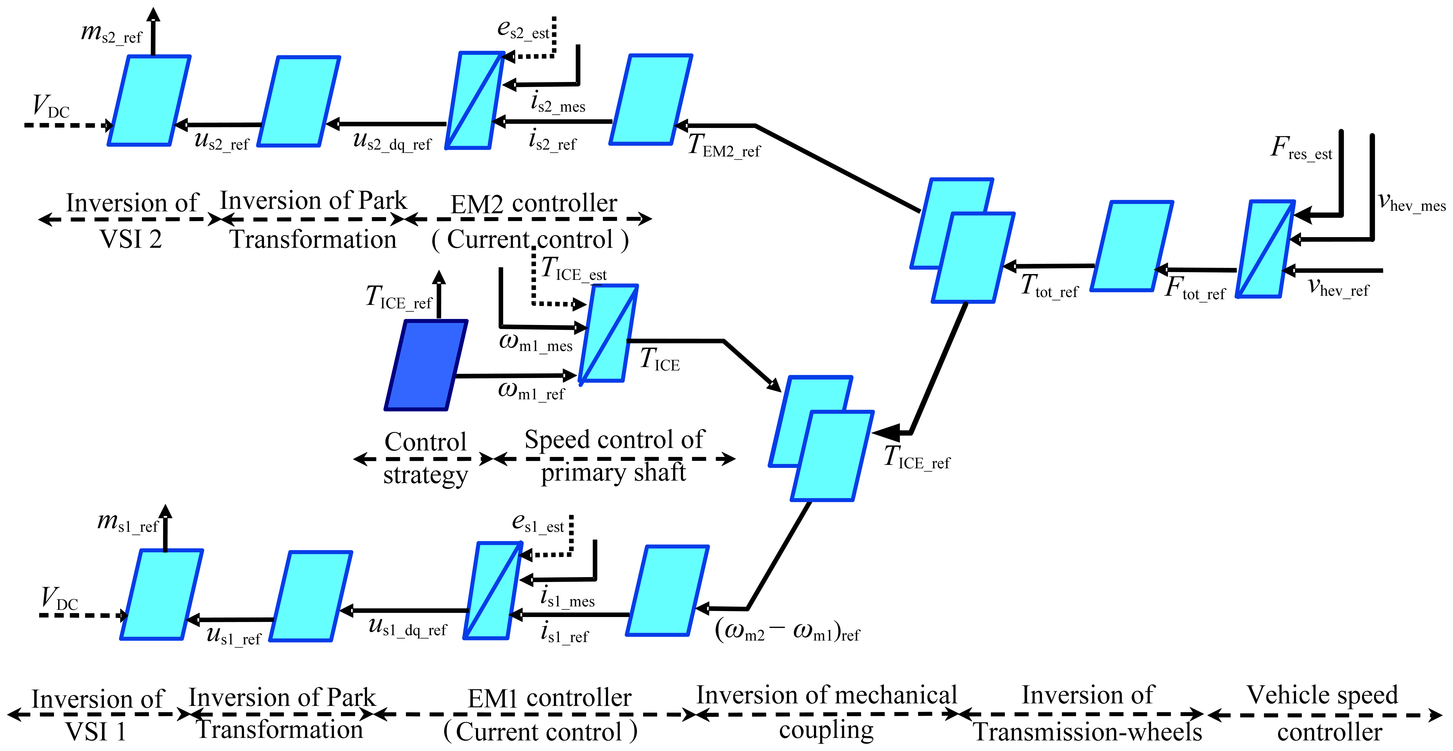
The model of all the power trains are built, including ICE, EVT, battery, power transmitting unit and vehicle load. The complex non-linear models, such as ICE and battery, are set up by theoretical analysis combined with experimental data, ensuring the accuracy of the simulation model and improving the simulation speed. With inversion based rules of EMR method, the inversion control model can be systematically deduced from the physical prototype model, as shown in Figure 4.
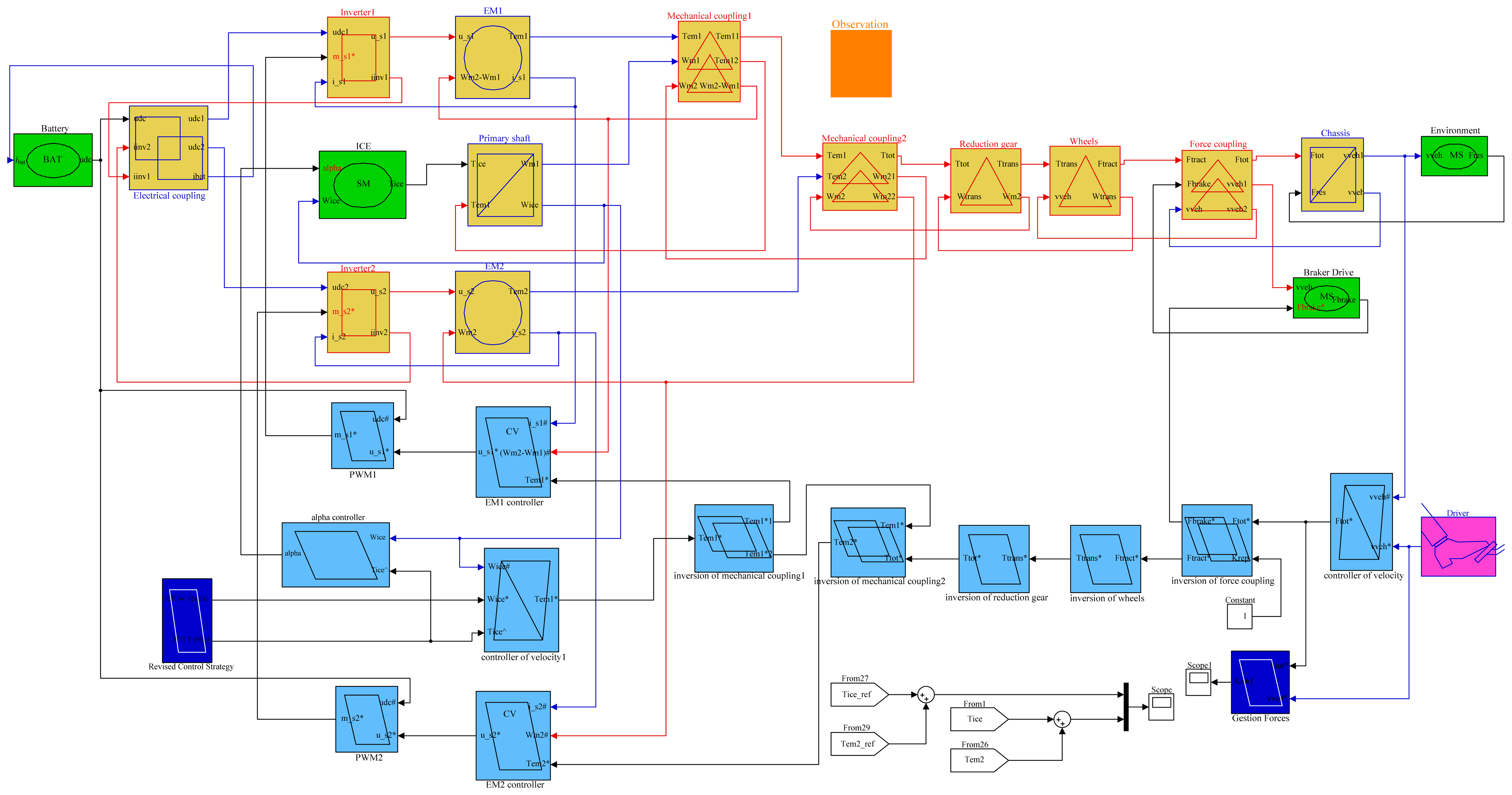
Then the simulation model of HEV based on EVT is established with the ideology of EMR, as shown in Figure 5.
The HEV based on EVT can achieve the operation modes of the Prius series HEV, so the design parameters of the Prius series HEV are used in the vehicle simulation, as shown in Table 2.
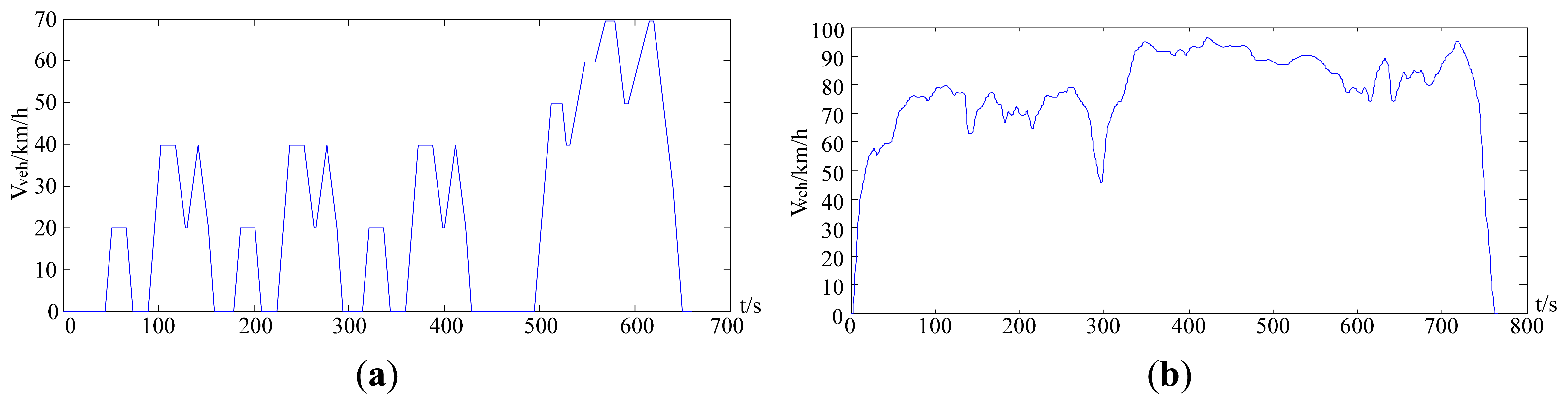
For the analysis of power management strategy of HEV, the 10.15 typical urban driving cycle and HWFET highway driving cycle are used for simulation, and the vehicle speed of two driving cycles vary with time as shown in Figure 6.
Two driving cycles contains different traffic characteristics. There are plenty of start-up, stop and idling status scenarios in the 10.15 typical urban driving cycle, which would reflect the fuel economy advantages. Then, in the HWFET highway driving cycle, there are higher vehicle speeds, higher average power requirements, no idling status, the acceleration and deceleration occurring frequently but on a small value, which is mainly used to focus on the dynamic performance. The characteristic parameters of the two driving cycles are shown in Table 3.
3. Analysis of the Power Management Strategy of EVT-Based HEV
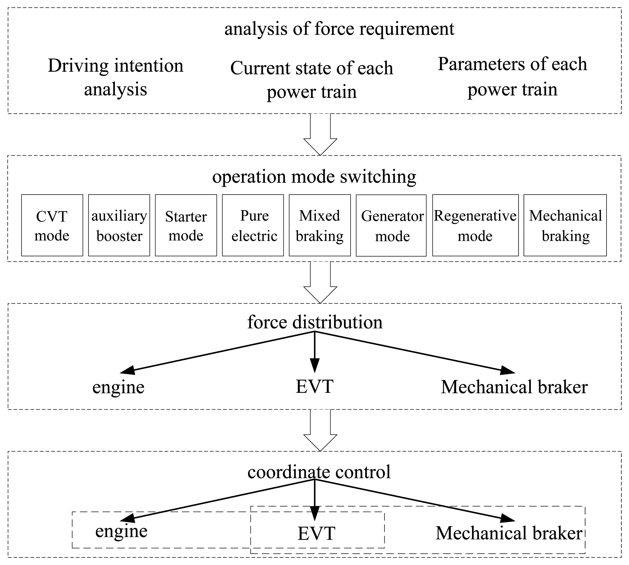
In the HEV control system, the purpose of the power management strategy is for distributing the power output for all the power trains, satisfying the power requirements and improving the fuel economy. Due to the changes of operation modes and force transmission mechanisms, the EVT-based HEV power management strategy is more complex than that of a traditional hybrid power system. Therefore, in order to clearly analyze and formulate the control strategy, this paper presents a kind of hierarchical control ideology for HEV. The vehicle control strategy is composed of four control levels, namely analysis of force requirement, operation mode switching, force distribution and coordinate control. The structure diagram of vehicle control strategy based on hierarchical control system is shown in Figure 7, and every control level is designed respectively. The design efficiency is improved, and the control strategy is easy to transplant for other power management strategy.
In the hierarchical HEV control ideology, the first control level is analysis of force requirements, which is the basis for the power management strategy. According to the signals of pedals and operation status of all the power trains, the force requirements are computed. The second control level of the hierarchical control ideology is operation mode switching, analyzing the operation modes of the HEV based on EVT. According to the force requirements and the operation status of the last sampling time, the next operation mode is determined to realize operation mode switching. The third control level is force distribution for all the power trains, and the outputs of all the power trains are optimally designed from the perspective of steady state. The fourth control level is coordinate control. Focusing on the dynamic control of the HEV based on EVT in the process of operation mode switching, the coordinate control strategy enhances the dynamic performance of the vehicle and driving comfort.
4. Force Requirement Analysis
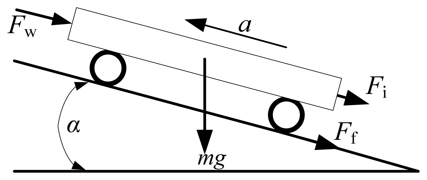
Force requirement analysis is the basis for the power management strategy. The force output is transferred by the mechanism and electricity in the HEV, so the HEV torque requirement is composed of two parts. One is the force requirement torque, and the other is the battery charging requirement torque. Firstly, the dynamic model of the vehicle is shown in Figure 8, and the force requirement torque can be computed according to the dynamic model of the vehicle.
According to Figure 8, force requirement torque can be computed in the Equation (1):
Substituting the Equations (2)–(5) in the Equation (1), the force requirement torque Treq_veh can be obtained from Equation (6):
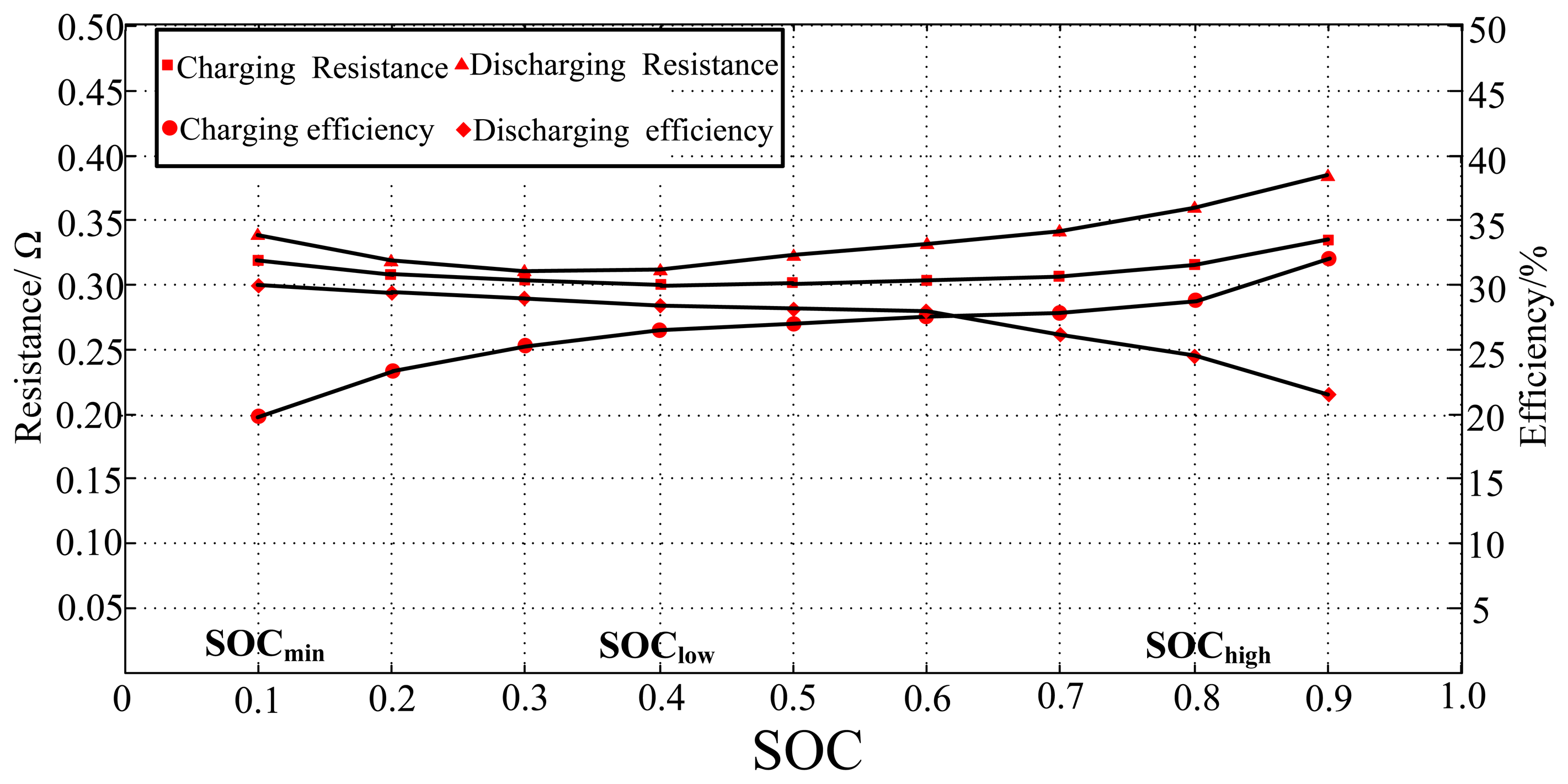
Plenty of energy is consumed by internal resistance when the battery is charged or discharged, so the optimal operation line of battery is set in the range of lower internal resistance for reducing the energy consumption. The optimal operation line is received from the pulse charge-discharge experiments of the battery, as shown in the Figure 9.
The charging requirement power of the battery is converted to the charging requirement torque, which is closely related to the SOC of battery. The charging requirement torque is obtained by Equation (7):
According to Equations (6) and (7), the force requirement of the vehicle Treq is shown in Equation (8):
5. Analysis of Operation Mode Switching
EVT can provide a lot of energy conversion ways, which can replace the continuously variable transmission (CVT), starter and generator to realize the function of CVT mode, starter mode, generator mode, regenerative braking mode, pure electric mode, and auxiliary booster mode [12,13].
5.1. Analysis of Operation Modes
The main work mode of the EVT is CVT mode. By the segregation and re-integration of the ICE output power, EVT can realize the same traditional automotive CVT function. If the energy consumption is not considered in the energy transfer and conversion process, and the output power of battery is zero, so the output energy of ICE is divided into two parts, shown in Equation (9):
Because the inner rotor of EVT is connected to ICE, the speed of the inner rotor is equal to speed of ICE, and the electromagnetic torque of inner machine (TEM1), is equal to the torque of ICE (TICE) in the steady state. Then we can get:
The final torque for driving HEV is the torque sum of the inner machine and outer machine, defined as below:
From Equation (11), EVT realizes the CVT mode, and then the transmission ratio (iEVT) can be defined as below:
The transmission ratio is a continuously variable value. At the CVT mode, the output electromagnetic powers of inner machine and outer machine are shown in Equation (13):
From Equation (13), we can get that the output electromagnetic powers of the inner machine and outer machine are equal in the CVT mode. When the transmission ratio is equal to 2, the inner machine and outer machine have the same speed and torque, respectively. When the value of the transmission ratio is between 1 and 2, the inner machine produces a larger torque and lower speed than the outer machine. When the value of transmission ratio is above 2, the inner machine has lower torque and larger speed than the outer machine. Without considering the energy loss in the process of energy transmission and conversion, the output power of the battery is zero in the CVT mode.
In the starter mode, the battery supports the energy to drive the inner machine, then the inner machine makes shaft speed of ICE rapidly reach the needed speed. At this moment, the outer machine remains in stationary state by the effect of road load, and the inner machine is equivalent to the traditional starter.
In the generator mode, the battery is charged by the inner machine or outer machine. When the SOC of the battery descends to the minimum threshold value (SOClow), the battery should be charged to improve the cycle life to avoid the deep discharge. If the HEV is in the stationary state, the outer machine does not work, and the ICE drives the inner machine to work as a generator. ICE charges the battery through the inner machine, and the mechanical energy is converted into electrical energy stored in the battery. If the HEV is in the motion state, SOC is detected lower than the minimum threshold value, so the output energy of ICE should be increased to meet the road load demands and charge the battery.
In the regenerative braking mode, the inner machine does not work, and the outer machine works as a generator which provides power back to the battery and slows down the vehicle. When the HEV cruises downhill or slows down, if the friction brake is used, the vehicle cannot get the energy feedback and the energy of motion is wasted. The friction brake is used when the vehicle must be stopped quickly or if the battery has abundant charge.
In the pure electric mode, the inner machine does not work, and the outer machine operates to drive the vehicle. The vehicle is equivalent to a pure electric vehicle. If the load demand power is low and the battery power is abundant, the engine can be shut down, and then the battery supports the energy needs.
In the auxiliary booster mode, the inner machine mainly works as a generator, and outer machine works as a motor. When the HEV is accelerating or climbing, the output energy of the ICE and battery can be added together to drive the HEV for improving its dynamic performance.
5.2. Operation Mode Switching
Firstly, the concept of loading rate is defined, which is rate of load torque divided by the maximum output torque of HEV, as shown in the Equation (14):
Loading rate could reflect the loading status of vehicle. According to the optimal operation line of ICE, optimal loading rate is defined, as shown in Equation (15):
At the starting-up stage of vehicle, the SOC of the battery is the main factor for determining operation mode. Due to the low thermal efficiency and poor emission, EVT is the better choice to drive the vehicle working in pure electric mode. If battery power is abundant, the ICE is shut down, and the battery supports the energy for EVT to start the vehicle. If battery power is insufficient, the inner machine makes the ICE shaft reach the speed needed rapidly, and the ICE works to drive the vehicle and charge the battery.
At low speed or under vehicle light load conditions, the ICE often works at idle status or low torque output state from the ICE load characteristic curve, with low thermal efficiency and poor emissions. So, similar to the vehicle start-up stage, according to the SOC of battery, EVT is preferred to provide the load torque requirements, improving the HEV efficiency. The critical judgment standard of light load condition is shown in Equation (16):
Under speed deceleration or braking conditions, the regenerative braking property is an important indicator of power performance for a HEV. When a HEV cruises downhill or runs slowing down, ICE is shut down, and the outer machine is working in the power generator state for recycling braking energy to charge the battery.
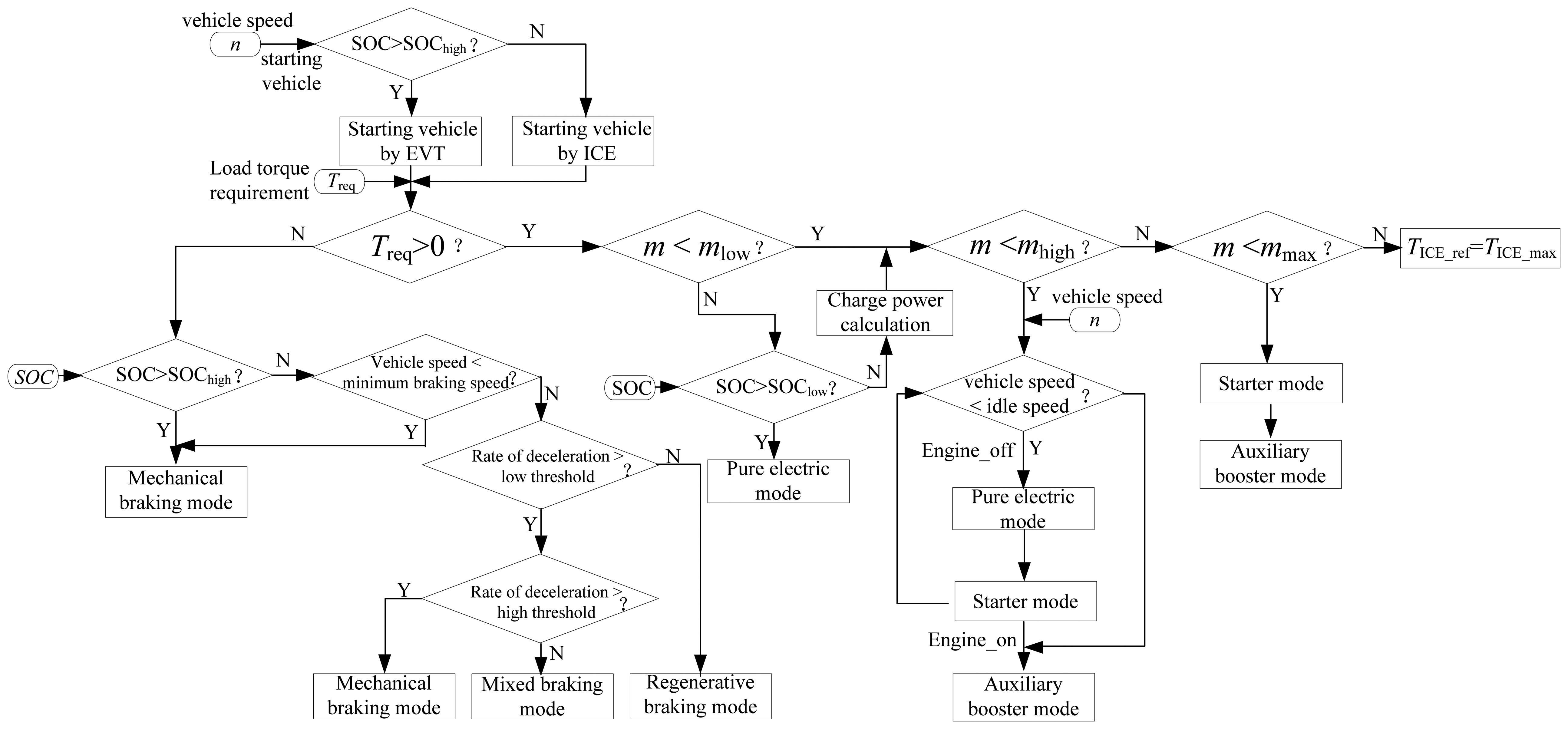
According to the above analysis, the operation mode switching strategy of EVT-based HEV is designed based on the logic thresholds, as shown in Figure 12, and the power requirements, current vehicle speed, and SOC of the battery are input parameters of the control strategy.
6. Analysis of Force Distribution
The force distribution is composed of torque assigning and transmission rate design of EVT. In this paper, the torque assigning is designed based on fuzzy logic control, and the transmission rate is designed based on power following strategy.
6.1. Torque Assigning Strategy Based on Fuzzy Logic Control
The HEV based on EVT can separate the ICE and road load, which can make the ICE operate around its optimal fuel economy area. HEV is driven by the synthetic torques of ICE and the outer machine, so it is of great importance for the control system to assign the output torque of the ICE and outer machine. In this paper, the output torques of ICE and EVT are assigned based on fuzzy logic control (FLC) strategy.
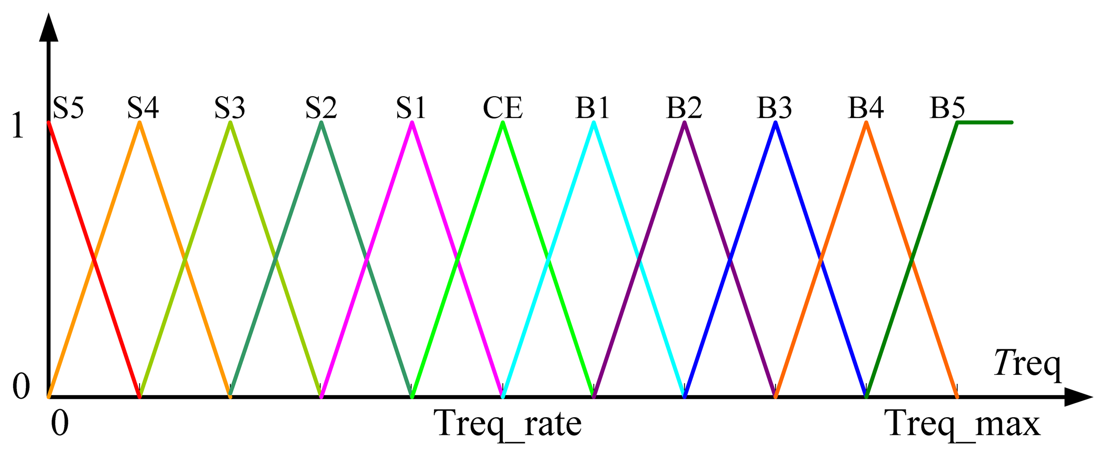
The FLC input variables are torque requirement Treq and SOC of the battery, and torque requirements can be calculated based on Equation (8). Through the FLC rules, the reference torque of outer machine can be solved, and the reference torque of the ICE can be deduced from Equation (19):
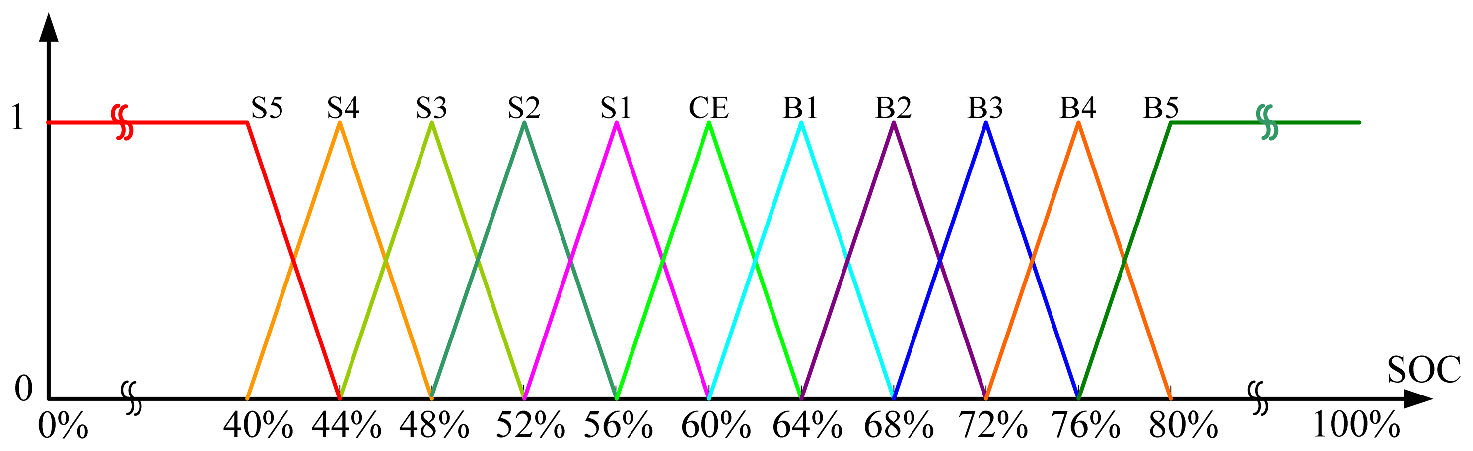
According to the torque requirement Treq, another 11 fuzzy sub-collections are defined to cover the input range of torque requirement, the membership function distribution is illustrated in the Figure 14, when Treq is lower than 0 (the required power is generative), it will be S5.
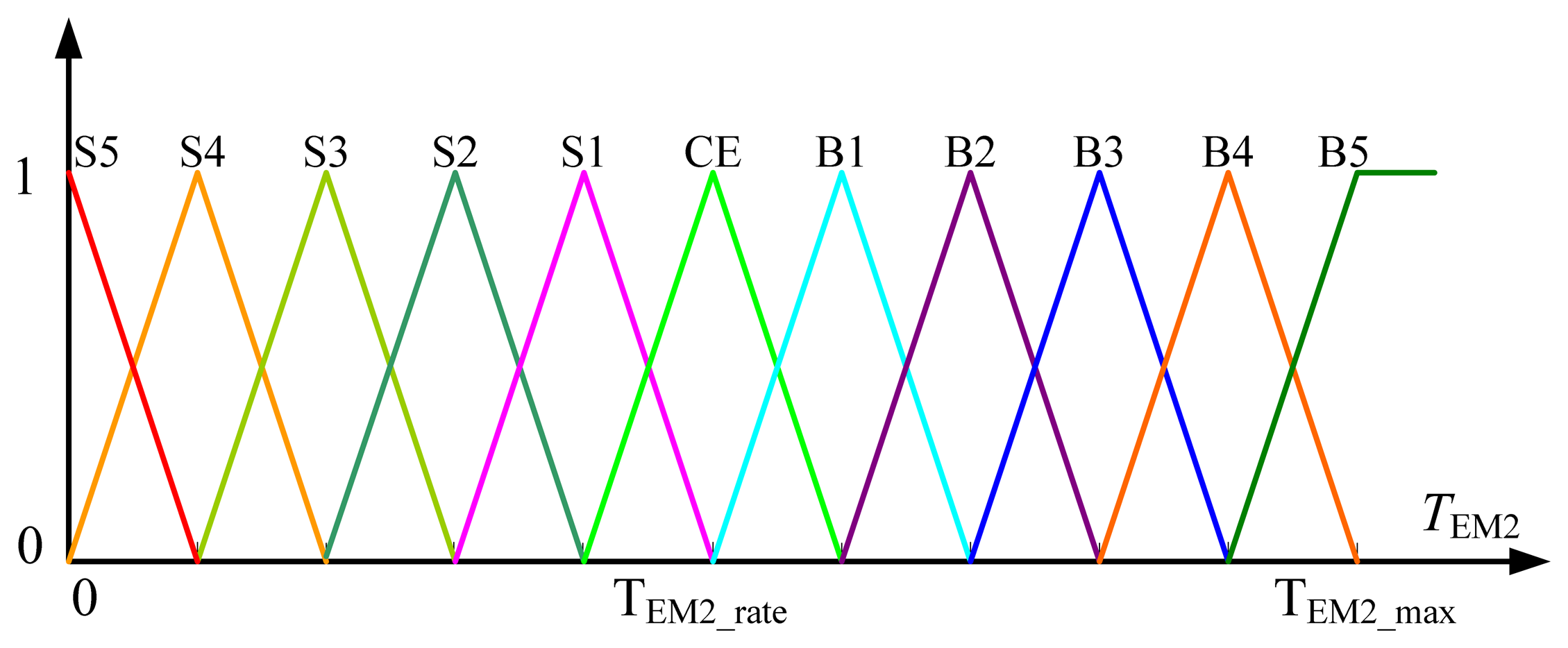
The reference torque of the outer machine is defined from 1 to 11 for the output of FLC, one corresponds to zero output torque of outer machine, six correspond to the rated output torque of outer machine and 11 correspond to its maximum output torque, the membership function is illustrated in Figure 15.
According to membership function of SOC and Treq, 121 fuzzy logic rules are built to solve the reference torque of the outer machine, as shown in Figure 16.
6.2. Transmission Rate Design of EVT Based on Power Following Strategy
The transmission ratio of the EVT is designed based on a power following strategy. Firstly, the optimal operation line of the ICE is described in Figure 17, where the ICE has a specific throttle level, speed and torque. Due to the operation point adjustment of EVT, the power following strategy keeps ICE working in the optimal operation line during all driving conditions, and the output of the ICE is different from the road load requirements. Speed control is adopted for the inner machine, changing the speed difference Δn from the speed required at the final gear to the optimal speed of the ICE. Torque control is adopted for the outer machine, changing the torque difference ΔT from the torque required at the final gear to the optimal torque of the ICE.
According to the requirement torque and SOC of battery, the optimal operation speed of ICE ωICE_opt is determined by power following strategy, and then transmission rate of EVT iEVT is computed in Equation (20):
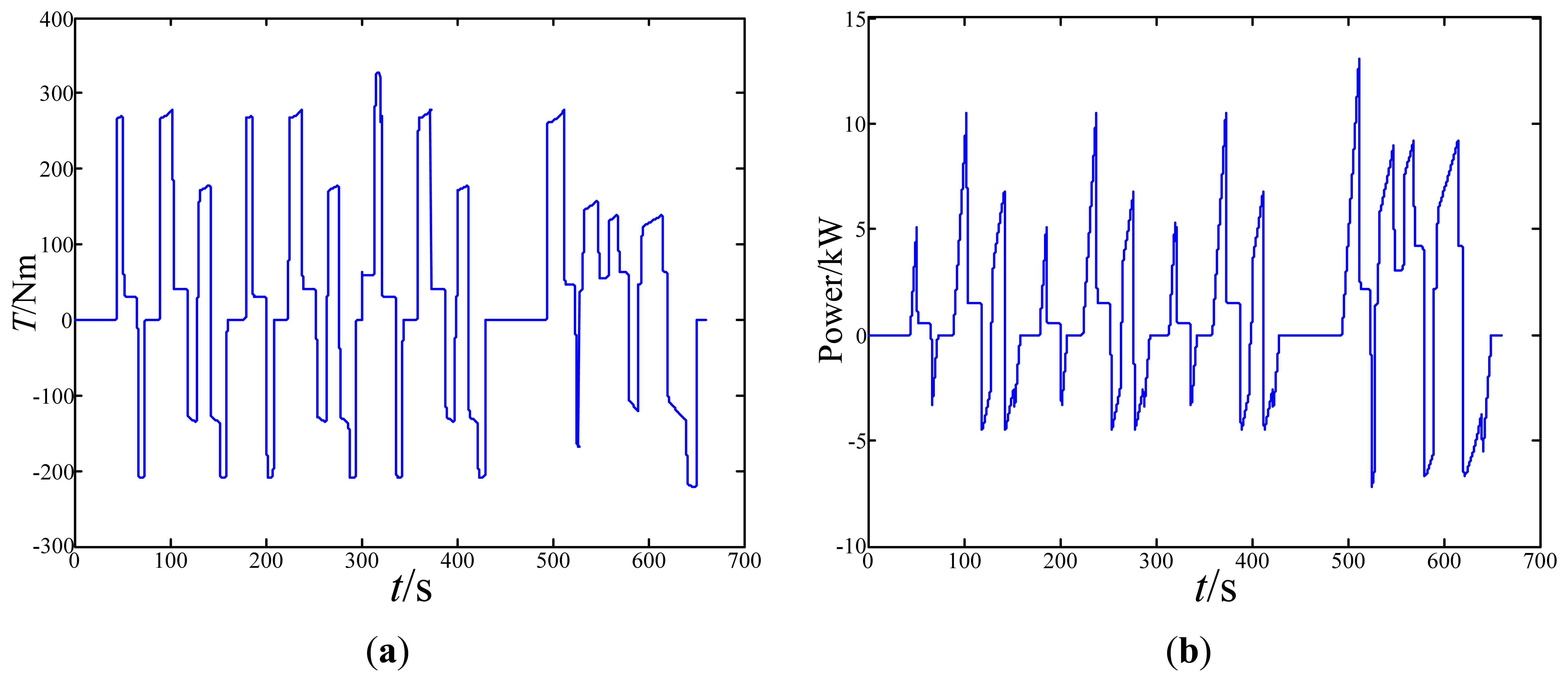
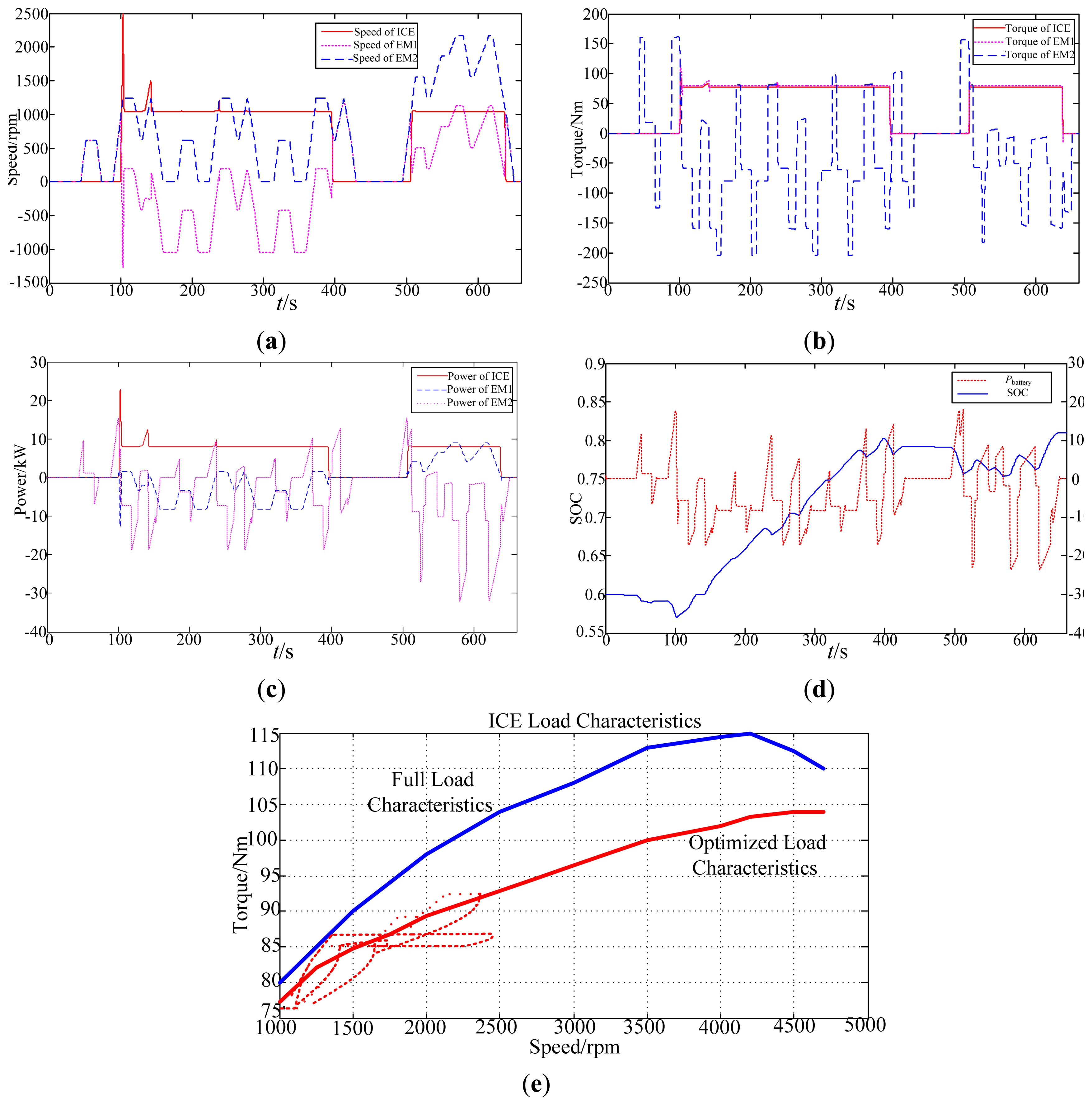
Road load power requirements are low, and the EVT outer machine often provide the driving force in the pure electric mode. The ICE is often shut down or working at low torque output state for low speed or light load conditions. The output torque of the inner machine follows the output torque of the ICE, and the speed of the inner machine varies with the vehicle speed. The battery is frequently charged or discharged during the deceleration or acceleration process, affecting SOC variation between SOClow and SOChigh.
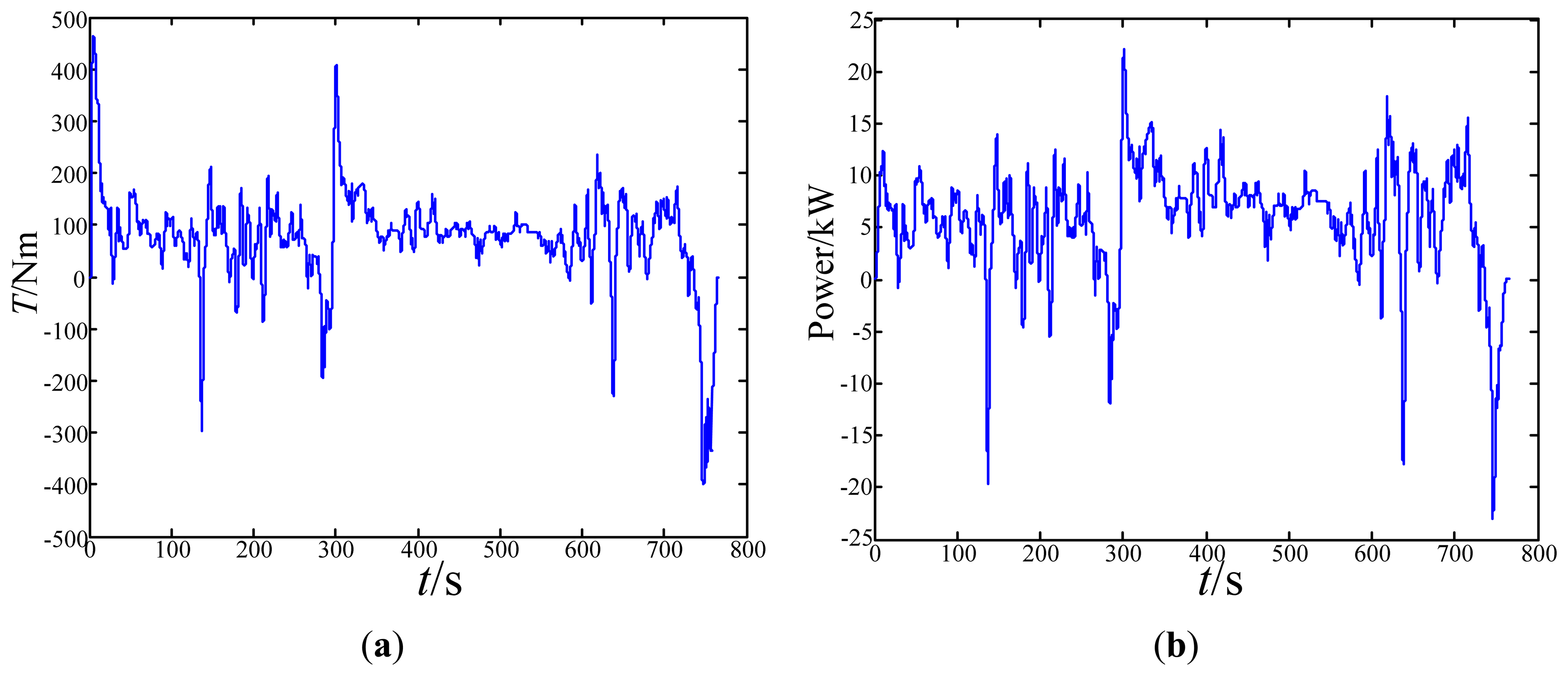
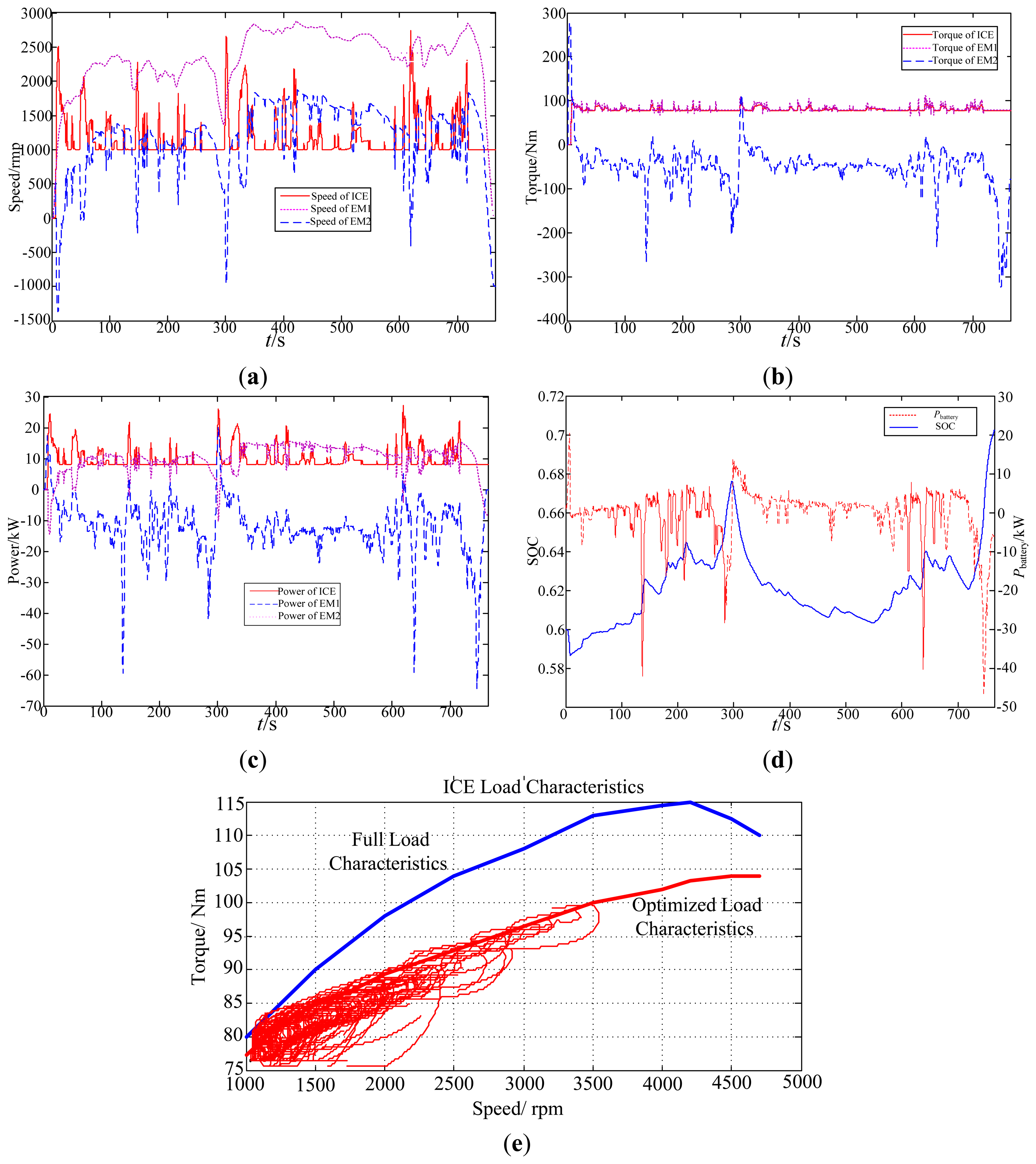
The simulation waveforms of the HWFET highway driving cycle based on power following strategy are shown in Figure 19. The power requirement of road loads is high, and the power output of the ICE follows the road load requirements based on the power following strategy.
The operation point of the ICE is adjusted by the speed control of the inner machine and the torque control of the outer machine, which is different from the required operation point at the final gear.
7. Analysis of Coordinate Control
The coordination control strategy aims to make the fluctuations of the dynamic torque output as small as possible in the mode switching process and to improve the dynamic response of the control system. Firstly, the force output analysis of the EVT-based HEV was carried out, shown in Figure 20.
According to Figure 20, the mechanical equations of the EVT-based HEV are expressed in Equations (21) and (22):
In the dynamic process of the operation mode switching, comparing the response time of the output torque, the ICE response is much longer than that of the EVT, which will cause torque fluctuation and damage the dynamic performance of the vehicle. For example, in the ICE start-up period, the inner machine works as a starter to drag ICE to a reference speed, and then the ICE ignition signal is activated. During the whole starting process, the output torque of the inner machine is coupled to the output shaft of the outer machine, resulting in fluctuations of the output drive torque Tdrive.
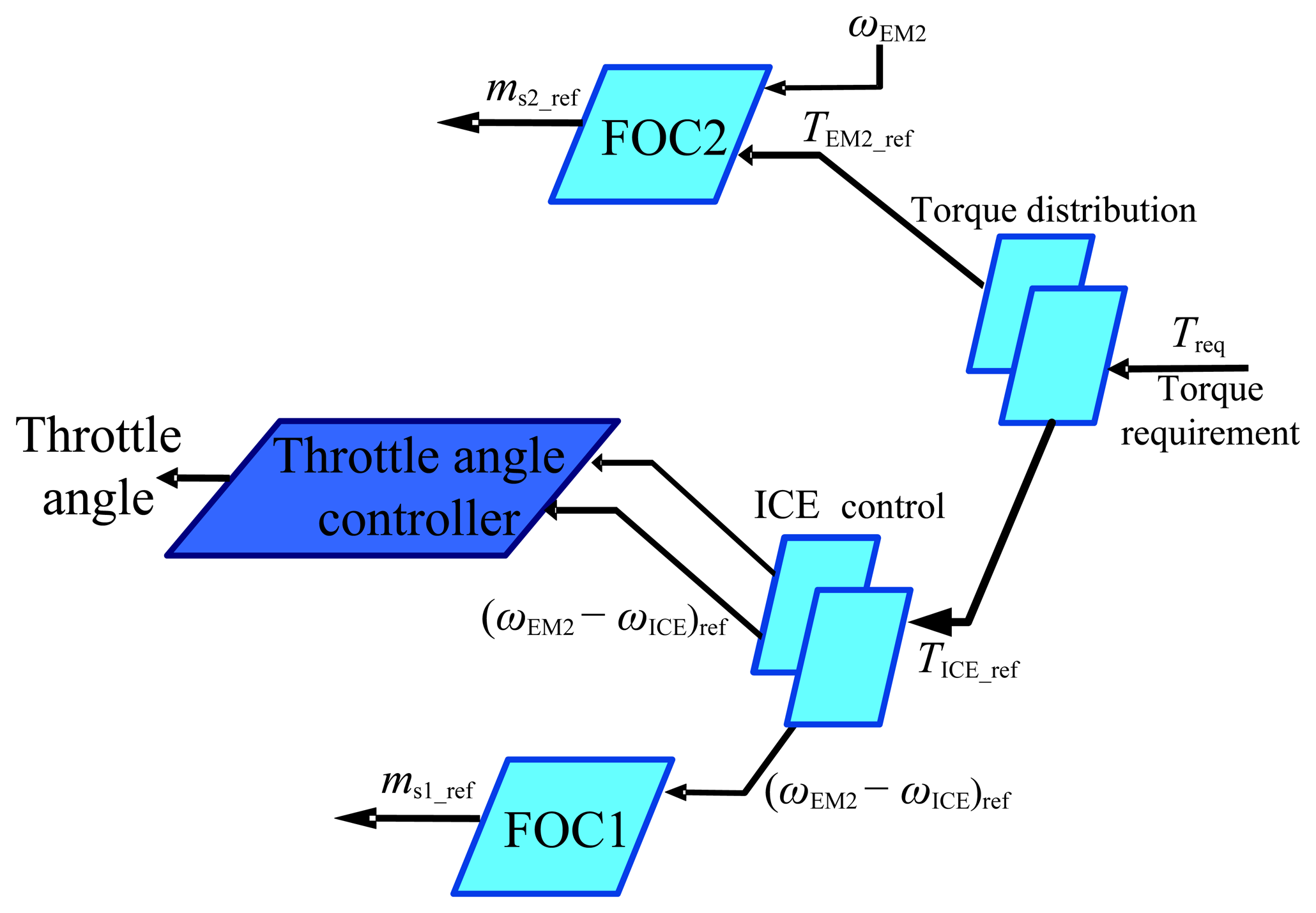
Taking into account the torque output response time of the ICE, this paper compensates the torque fuzzy logic control reference and the output torque of the outer machine is adjusted by the ICE instantaneous torque estimation. The ICE is a strong non-linear system, so it is very difficult to establish an accurate mathematical model and directly estimate the ICE torque. Because the output torque of the ICE is transmitted by the inner machine of the EVT, the ICE output torque could be obtained by the torque estimation of the EVT inner machine. Therefore, the actual torque command of the outer machine in the operation mode switching process is shown by Equation (23):
In the coordinate control strategy, the output torque of the outer machine is limited by the output capability, and the constraint condition is shown in Equation (24):
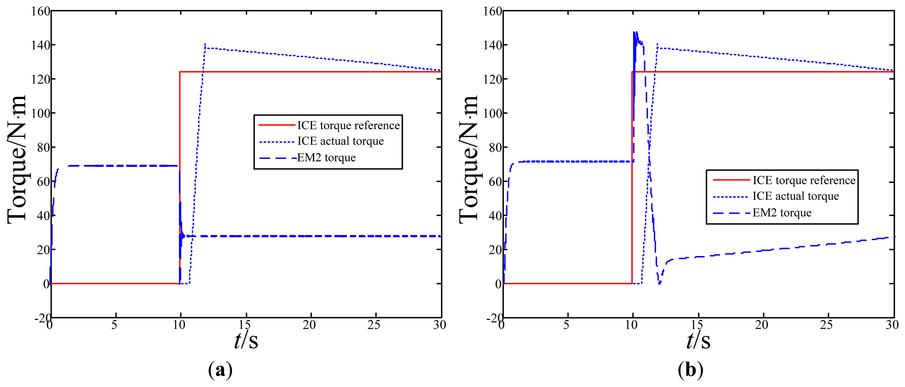
In the simulation analysis of coordinate torque control, the torque of the outer machine can respond quickly to the reference value from pure electric mode switching to auxiliary booster mode, but the torque response of the ICE has a relatively long time delay. The HEV driving torque is reduced without torque compensation in Figure 23a. The torque compensation is added by increasing the output torque of the outer machine in the operation mode switching process, improving the dynamic performance of the control system, as shown in Figure 23b.
8. Experiment Validity Analysis of the EVT-Based HEV
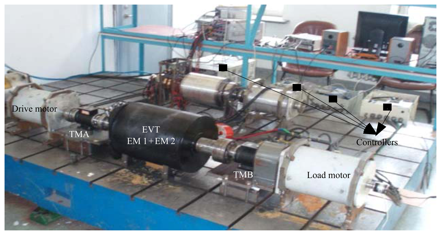
The experiment test bench of the EVT-based HEV is shown in Figure 24. Due to the laboratory conditions, the ICE is simulated by an induction machine used as driving motor, and the road load is simulated by another induction machine used as load motor. dSPACE is used as the vehicle controller for achieving the power management strategy.
In the experimental process, the HEV operation mode is switched from auxiliary booster mode to pure electric mode. According to the torque requirements of the vehicle controller, the ICE and EVT are controlled. The response waveforms of torque without coordinate control are shown in Figure 25, and the fluctuation of summed driving torque is up to 40 Nm.
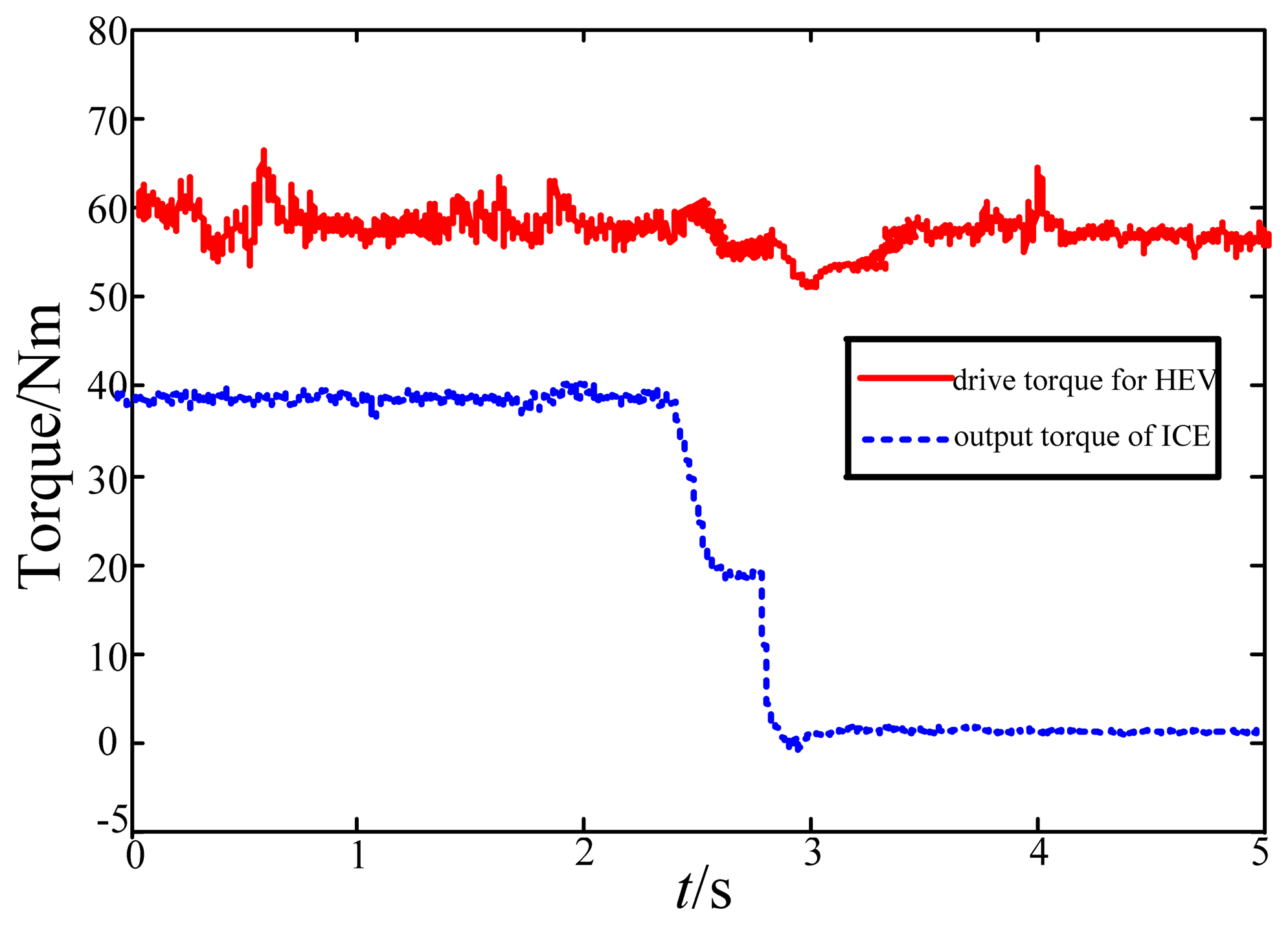
The response waveforms of torque with coordinate control are shown in Figure 26, and the fluctuation of summed driving torque is less than 5 Nm. The ICE output torque is compensated by the EVT outer machine to enhance the dynamic performance of the HEV.
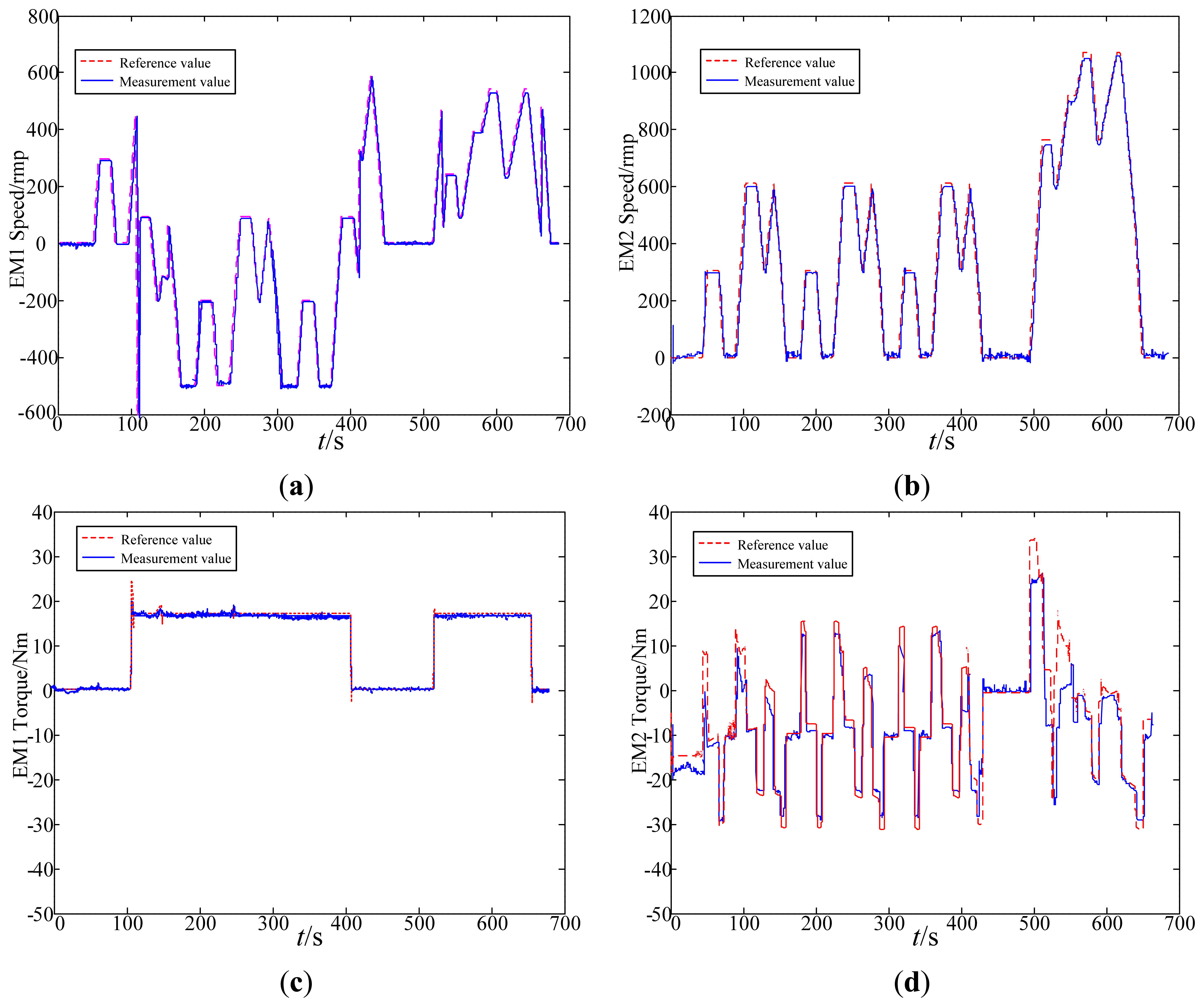
Finally, EVT-based HEV experiment is executed under the 10.15 urban driving cycle. The force distribution for the ICE and EVT is based on the power following strategy and fuzzy logic control, whose experiment waveforms are shown in Figure 27. According to the power management strategy in this paper, the operation mode switching is smoothly achieved, and the errors between reference and actual values for torque and speed are very small.
9. Conclusions
This paper analyzed the power management strategy for an EVT-based HEV, deriving the main conclusions as follows:
- (1)
A kind of hierarchical HEV control ideology is proposed. The vehicle control strategy is composed of four levels, namely analysis of force requirement, operation mode switching, force distribution and coordinate control.
- (2)
EVT is especially suitable for application in HEVs with a lot of energy conversion ways. EVT can replace the CVT, starter, generator to realize the functions of CVT mode, starter mode, generator mode, regenerative braking mode, pure electric mode, and auxiliary booster mode. This paper analyzes the operation modes of a HEV based on EVT. According to the power requirements, current vehicle speed, SOC of the battery, a rule control strategy based on the logic thresholds is designed to solve the problem of operation mode switching.
- (3)
The force distribution strategy is analyzed. The output torque of the ICE and EVT is assigned based on a fuzzy logic control strategy, and the transmission ratio of the EVT is designed based on a power following strategy.
- (4)
Focusing on the dynamic control of a HEV based on EVT in the process of operation mode switching, a new dynamic torque coordination control strategy is proposed for the EVT used in HEVs. The dynamic torque coordination control strategy improves the dynamic performance of the HEV, reducing the torque fluctuations during the switching process.
- (5)
An EVT-based HEV simulation model is built with the ideology of EMR, and an experiment test bench is built. The simulation and experimental results demonstrate the feasibility of the proposed power management strategy. This research should provide great help and design references for further study and design of EVTs.
Acknowledgments
This work was Project No. CDJZR13150007 supported by the Fundamental Research Funds for the Central Universities.
Conflicts of Interest
The authors declare no conflict of interest.
References
- Hoeijmakers, M.J.; Ferreira, J.A. The Electrical Variable Transmission. Proceedings of the IEEE Industry Applications Conference, Seattle, WA, USA, 3–7 October 2004; pp. 2770–2777.
- Hoeijmakers, M.J.; Rondel, M. The Electrical Variable Transmission in a City Bus. Proceedings of the 35th Power Electronics Specialists Conference, Aachen, Germany, 20–25 June 2004; pp. 2773–2778.
- Cheng, Y.; Duan, F.Y.; Cui, S.M. The Design Principle of Electric Motors and Driving Systems for Electric Vehicles. Proceedings of the 8th International Conference on Electrical Machines and Systems, Nanjing, China, 27–29 September 2005; pp. 802–805.
- Xu, L.Y. A New Breed of Electrical Machines-Basic Analysis and Applications of Dual Mechanical Port Electric Machines. Proceedings of the 8th International Conference on Electric Machines and Systems, Nanjing, China, 27–29 September 2005; pp. 24–31.
- Guo, X.H.; Wen, X.H.; Xu, L.Y.; Zhao, F.; Liu, J. Simulation and Experiment Analysis of Dynamic Process for an EVT Based on Dual Mechanical Port Electric Machine. Proceedings of the Power Electronics and Motion Control Conference, Wuhan, China, 17–20 May 2009; pp. 2010–2014.
- Zheng, P.; Liu, R.R.; Wu, Q.; Zhao, J.; Yao, Z.Y. Magnetic coupling analysis of four-quadrant transducer used for hybrid electric vehicles. IEEE Trans. Magn. 2007, 43, 2597–2599. [Google Scholar]
- Zheng, P.; Liu, R.R.; Peter, T.; Erik, N.; Chandur, S. Research on the cooling system of a 4QT prototype machine used for HEV. IEEE Trans. Energy Convers. 2008, 23, 61–66. [Google Scholar]
- Guo, X.Z.; Wen, X.H.; Xu, L.Y.; Zhao, F.; Liu, J. Vibration Reducing in the Process of Engine Start-Stop for Electric Variable Transmission. Proceedings of the Power Electronics and Motion Control Conference, Wuhan, China, 17–20 May 2009; pp. 2001–2004.
- Magnussen, F.; Thelin, P.; Sadarangani, C. Design of Compact Permanent Magnet Machines for a Novel HEV Propulsion System. Proceedings of the 20th International Electric Vehicle Symposium and Exposition, Long Beach, CA, USA, 15–19 November 2003; pp. 1–12.
- Xu, Q.W.; Song, L.W.; Tian, D.W.; Cui, S.M. Research on Intelligence Torque Control for the Electrical Variable Transmission Used in Hybrid Electrical Vehicle. Proceedings of the 14th International Conference on Electric Machines and Systems, Beijing, China, 20–23 August 2011; pp. 1–6.
- Bouscayrol, A.; Davat, B.; Fornel, B.; Hautier, J.P. Multi-Machine Multi-Converter System for Drives: Analysis of Coupling by a Global Modeling. Industry Applications Conference, Rome, Italy, 8–12 October 2000; pp. 1474–1481.
- Xu, L.Y.; Zhang, Y.; Wen, X.H. Multi-Operational Modes and Control Strategies of Dual Mechanical Port Machine for Hybrid Electrical Vehicles. Proceedings of the 42th Industry Application Conference, New Orleans, LA, USA, 23–27 September 2007; pp. 1710–1717.
- Cheng, Y.; Cui, S.M.; Song, L.W.; Chan, C.C. The study of the operation modes and control strategies of an advanced electromechanical converter for automobiles. IEEE Trans. Magn. 2007, 43, 430–433. [Google Scholar]


| Graphical symbols | Symbol description | Graphical symbols | Symbol description | Graphical symbols | Symbol description |
|---|---|---|---|---|---|
 | Source of energy |  | Electrical converter (without energy accumulation) | 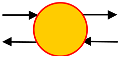 | Electromechanical converter (without energy accumulation) |
 | Mechanical converter (without energy accumulation) | 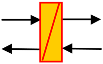 | Element with energy accumulation | 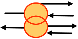 | Coupling device (distribution of energy) |
| Category | Parameter name | Value | Unit |
|---|---|---|---|
| Vehicle | Curb weight | 1345 | kg |
| Cargo weight | 400 | kg | |
| Frontal area | 1.746 | m2 | |
| Coefficient of air resistance | 0.3 | - | |
| Battery | Type | Ni-MH | - |
| Capacity | 6.5 | A·h | |
| Rated voltage | 201.6 | V | |
| Internal resistance | 0.0114 | Ω | |
| ICE | Displacement | 1.5 | L |
| Max power | 57 (5000 rpm) | kW | |
| Max torque | 115 (4000 rpm) | N·m | |
| Max speed | 6000 | rpm | |
| Power-train | Final gear ratio | 4.113 | - |
| Efficiency | 0.95 | - | |
| Tire | Radius | 0.2929 | m |
| Coefficient of rolling resistance | 0.01 | - |
| Driving cycle | Time (s) | Maximum speed (km/h) | Average speed (km/h) | Maximum acceleration (m/s2) | Maximum deceleration (km/h) | Idling time (s) |
|---|---|---|---|---|---|---|
| 10.15 | 660 | 69.97 | 22.68 | 0.79 | −0.83 | 215 |
| HWFET | 765 | 96.4 | 77.58 | 1.43 | −1.48 | 6 |
© 2014 by the authors; licensee MDPI, Basel, Switzerland. This article is an open access article distributed under the terms and conditions of the Creative Commons Attribution license( http://creativecommons.org/licenses/by/3.0/).
Share and Cite
Xu, Q.; Cui, S.; Song, L.; Zhang, Q. Research on the Power Management Strategy of Hybrid Electric Vehicles Based on Electric Variable Transmissions. Energies 2014, 7, 934-960. https://doi.org/10.3390/en7020934
Xu Q, Cui S, Song L, Zhang Q. Research on the Power Management Strategy of Hybrid Electric Vehicles Based on Electric Variable Transmissions. Energies. 2014; 7(2):934-960. https://doi.org/10.3390/en7020934
Chicago/Turabian StyleXu, Qiwei, Shumei Cui, Liwei Song, and Qianfan Zhang. 2014. "Research on the Power Management Strategy of Hybrid Electric Vehicles Based on Electric Variable Transmissions" Energies 7, no. 2: 934-960. https://doi.org/10.3390/en7020934
APA StyleXu, Q., Cui, S., Song, L., & Zhang, Q. (2014). Research on the Power Management Strategy of Hybrid Electric Vehicles Based on Electric Variable Transmissions. Energies, 7(2), 934-960. https://doi.org/10.3390/en7020934