1. Introduction
Mechanical gearboxes are widely used as the transmission devices connecting electrical machines and loads in low-speed high-torque applications. However, the mechanical transmission system has some inherent shortcomings. Mechanical gearboxes rely on the mesh of metal teeth to transfer the torque and energy, which will inevitably bring about problems of friction loss, mechanical fatigue, acoustic noise and undesired vibrations [
1,
2]. Cooling and regular maintenance are also required, which may further increase the running cost of the mechanical gearboxes. Although the direct-drive concept, which may directly drive the load by the electrical machine, could avoid the above problems, the accompanying increased volume of the direct-drive electrical machine as well as the increased cost in processing, transportation and installation may limit its applications [
3,
4]. Especially, with the increasing of the power capacity and the decreasing of the rated rotating speed, such as wind power conversion systems, the disadvantages of the above two drive trains may be even amplified [
5].
As a counterpart of the mechanical gearbox in a magnetic drive, namely magnetic gear, non-contact torque transmission, could be realized through the coupling of magnetic fields excited by permanent magnets (PMs) [
6]. Therefore, the problems caused by contact mechanisms will be eliminated, and then higher reliability and stability could be achieved by the magnetic gears. However, magnetic gears have not attracted much attention since their initial development because of the low torque capability caused by the poor utilization of the PMs [
7]. Recently, a more sensible topology for magnetic gears was proposed in [
8,
9]. By adopting a coaxial arrangement of two PM rings, all of the PMs could contribute to the torque transmission simultaneously, hence a torque density exceeding 100 kNm/m
3 could be achieved [
8]. A detailed comparison between the planetary mechanical and coaxial magnetic gears has been provided in [
10], showing that coaxial magnetic gears could have comparable or better performance than their mechanical counterparts while avoiding many mechanical drawbacks. Some other comparisons in [
7] and [
11] indicate that the coaxial magnetic gears exhibit a remarkably improved efficiency with a comparable or smaller volume than some classical commercial mechanical gearboxes.
Several attempts and studies to optimize the performance of the coaxial magnetic gear have been made over the last decade. In [
9] and [
12], it can be seen that the gear ratio and the combination of the pole-pair numbers of the two PM rings have an essential effect on the maximum torque. The effect of the pole-piece dimension on torque transmission has also been illustrated in [
13], indicating that the pole-piece shape affects the magnetic flux leakage, and thereby affects the torque transmission. Reference [
14] maximized the torque capability of the coaxial magnetic gear by taking into consideration of the PM volume, air-gap length, gear ratio and pole-pieces size, respectively. Moreover, some partial couplings of the above design parameters were also investigated to predict their integrated effect on the torque production. The mesh adjustable finite-element algorithm, which may reduce the calculation time of the FEM to some extent, was applied in [
15] to optimize the dimensions of the coaxial magnetic gear with the aim of improving the torque performance. All of the above researches were based on the FEM, which is time-consuming and inflexible when to optimize the studied magnetic gear. Moreover, most of the previous analyses and design optimizations failed to provide a comprehensive representation about the coupling effect of key design parameters on the torque capability. In this paper, an analytical model, which is a fast method to obtain field distribution in the magnetic gear, is employed to conduct fast global optimizations, where the coupling between all design parameters will be taken into account by applying the particle swarm optimization (PSO) algorithm.
Although recent developments in magnetic gears have enhanced the torque capability, the cost of the magnetic gears was rarely mentioned or it was relegated to second place for consideration. Due to the high consumption of rare earth PMs, the material cost seems to be the biggest obstacle hindering industrial applications. Reference [
16] carried out a comparative study between the non-rare-earth and rare-earth PM coaxial magnetic gears, and the results indicate that with emphasis on the cost effectiveness, non-rare-earth PMs are preferred for coaxial magnetic gears, but the torque capability is compromised. To decrease the PM usage and improve the mechanical structure, an artful topology, which buries PMs with the same polarity into the iron core of the outer rotor, was proposed in [
17]. Half of the PMs on the outer rotor were thus removed, but its torque density may be unattractive compared to the topology described in [
8]. Therefore, the torque transmission capability of the coaxial magnetic gear exhibits a strong correlation with the material cost. Aiming at better commercial applications, this paper seeks a compromise between the torque performance and material cost. The cost will be also regarded as an important objective in the PSO design.
Section 2 of this paper describes the configuration of the studied magnetic gear and presents an initial design. In
Section 3, an analytical model is developed and validated by the finite elements method.
Section 4 studies the effect of the key design parameters on torque capability. Global optimizations with the considerations of torque capability and material cost are presented in
Section 5.
Section 6 concludes this paper.
2. Configuration and Initial Design
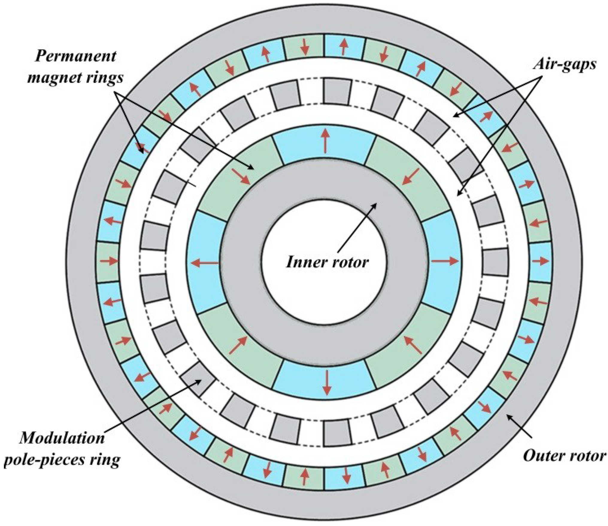
The configuration of the coaxial surface-mounted PM magnetic gear is shown in
Figure 1. It consists of two rotors and a stationary modulation ring.
Figure 1.
Configuration of the studied magnetic gear.
Figure 1.
Configuration of the studied magnetic gear.
The modulation ring with a number of ferromagnetic modulation pole-pieces is sandwiched between the two rotors, and two air-gaps are thereby formed to separate the above three components from each other. In order to realize the function of a gearbox, the magnetic fields with different pole-pairs in the two air-gaps should be generated by mounting different pole-pairs of the PM rings on the outer and inner rotors. The modulation ring could act as a mediator to match the pole-pairs differential between the two magnetic fields, when satisfying the following relationship [
8]:
where
po and
pi are the pole-pairs of the outer and inner PM rings, respectively; and
Ns is the number of the modulation pole-pieces.
The corresponding speed relationship can be given by:
where
no and
ni are the rotating speeds of the outer and inner rotors, respectively; and
Gr is the gear ratio.
To conduct a convenient analysis and optimization, the volume of the coaxial magnetic gear studied in this paper is fixed, and confined to 320 mm in outer diameter and 100 mm in stack length from the point view of reducing the end effects. In order to avoid magnetic saturation, the thickness of the rotor yoke is set to be equal to the half of the arc width of the PM block mounted on it. Identical ferromagnetic materials are employed for the pole-pieces and the rotor yokes. The gear ratio
Gr usually is an important factor for the gearbox, which could be viewed as a good starting point for designing a coaxial magnetic gear. According to the specification of single-stage mechanical gears listed in [
7], the gear ratio
Gr of the studied magnetic gear is set around 5.5:1 in this paper.
Table 1 lists the initial design of the studied magnetic gear.
Table 1.
Initial design of the studied magnetic gear.
Table 1.
Initial design of the studied magnetic gear.
| Symbol | Quantity | Value |
|---|
| Gr | gear ratio | around 5.5:1 |
| Dm | outer diameter of the magnetic gear | 320 mm |
| po / pi | PM pole-pair combination | 23/4 |
| τm/τp | pole-piece width/pole pitch ratio | 0.5 |
| τl/τp | pole-piece length/pole pitch ratio | 0.5 |
| to | thickness of the outer PM ring | 6 mm |
| ti | thickness of the inner PM ring | 6 mm |
| δo | length of the outer air-gap | 1 mm |
| δi | length of the inner air-gap | 1 mm |
| L | stack length | 100 mm |
| Br | remanence of the PM | 1.2 T |
3. Analytical Model of the Magnetic Gear
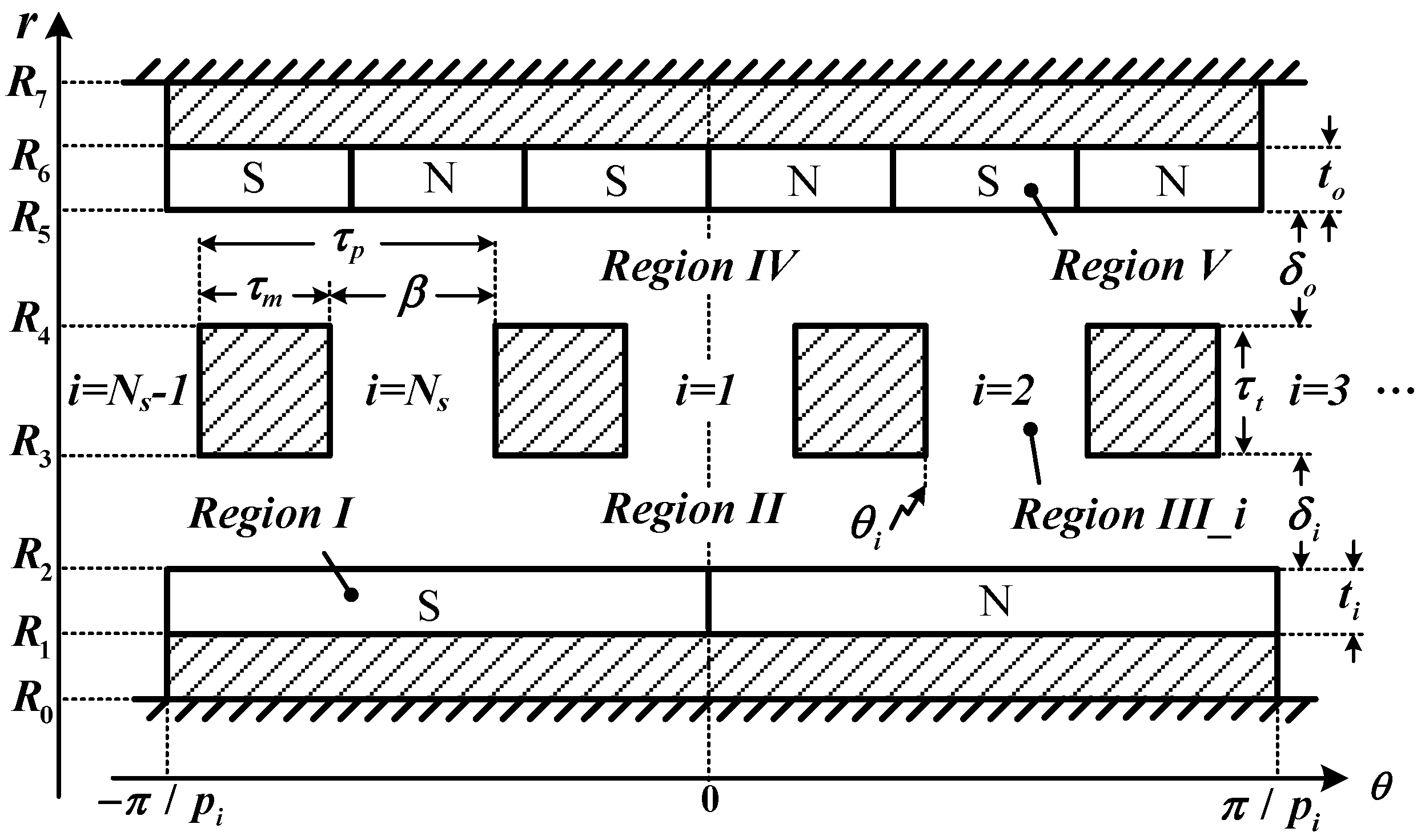
The studied magnetic gear could be represented in the pseudo polar coordinate system, as shown in
Figure 2. For the sake of formulating the magnetic field distributions, the calculation domain in the studied magnetic gear is partitioned into five regions [
18,
19],
i.e., the inner and outer PM rings (Region I and Region V), the inner and outer air-gaps (Region II and IV), and the slots between modulation pole-pieces (Region III_
i,
i = 1, 2, 3…
Ns.). For simplicity, the analytical model in this paper is established by magnetic vector potential in two-dimensional polar coordinate plane with the following assumptions:
- (1)
Infinite permeability of ferromagnetic material;
- (2)
Neglected end effect;
- (3)
Relative recoil permeability of PM is 1;
- (4)
Ideal radial magnetization.
Figure 2.
Analytical model in the pseudo polar coordinate system.
Figure 2.
Analytical model in the pseudo polar coordinate system.
The magnetic vector potentials
A(
r,θ) in the studied magnetic gear are governed by a set of 2nd partial differential equations:
where
Mr is the radial magnetization distribution of PMs and may be expressed as the Fourier series:
where:
where φ is the initial angle of the PMs rings, which indicates the angle displacement of the two rotors regarding the rotor positions displayed in
Figure 2; and
p is the pole-pair number.
The corresponding boundary conditions to be satisfied by the solution to Equations (4) and (5) are:
where
R1,
R2,
R3,
R4,
R5,
R6, β and θ
i are defined in
Figure 2.
3.1. General Solution in the PM Regions
The magnetic vector potentials
AI/V(
r,θ) in PM regions are governed by Poisson’s equations given in Equation (4). By using the separation of variables method and superposition law, the general solutions of Region I and V could be written as:
where:
where:
where
n is harmonic order;
,
,
,
,
,
,
and
are the unknown coefficients to be determined.
3.2. General Solution in the Air-Gap Regions
The magnetic vector potentials
AII/IV(
r,θ) in the air-gap regions are governed by Laplace’s equations given in Equation (5). By using the separation of variables method, the general solutions of Region II and IV could be given by:
where
,
,
,
,
,
,
and
are undetermined coefficients.
The radial and tangential flux distribution
Br and
Bθ in the two air-gap regions can be deduced from the magnetic vector potentials by:
3.3. General Solution in the Slot Regions
The magnetic vector potentials
in the
ith slot are governed by the Laplace’s equation as well. Taking into account the boundary conditions given in Equations (13) and (14) [
20], the general solution can be obtained as:
where
k is the harmonic order;
,
,
and
are the coefficients to be determined.
The relationship between the unknown coefficients could be established by applying Equations (8)–(12) and Equations (15)–(19). The numerical solution could be then obtained by using numerical calculation software such as Matlab.
3.4. Magnetic Torque
The magnetic torque is one of the most important performance indexes of the magnetic gear and is one of the key optimization objectives in this paper. After having determined the magnetic field distributions in the two air-gaps, the magnetic torques exerted on the inner and outer rotors,
Ti and
To, could be obtained by using Maxwell stress tensor [
18,
20], and given by:
where
ri and
ro are the radius of the integration paths in the inner and outer air-gaps, respectively.
3.5. Comparison with FEM Calculations
To validate the analytical model developed above, the corresponding non-linear FEM model is established. The specifications of the studied magnetic gear for comparison are given in
Table 1.
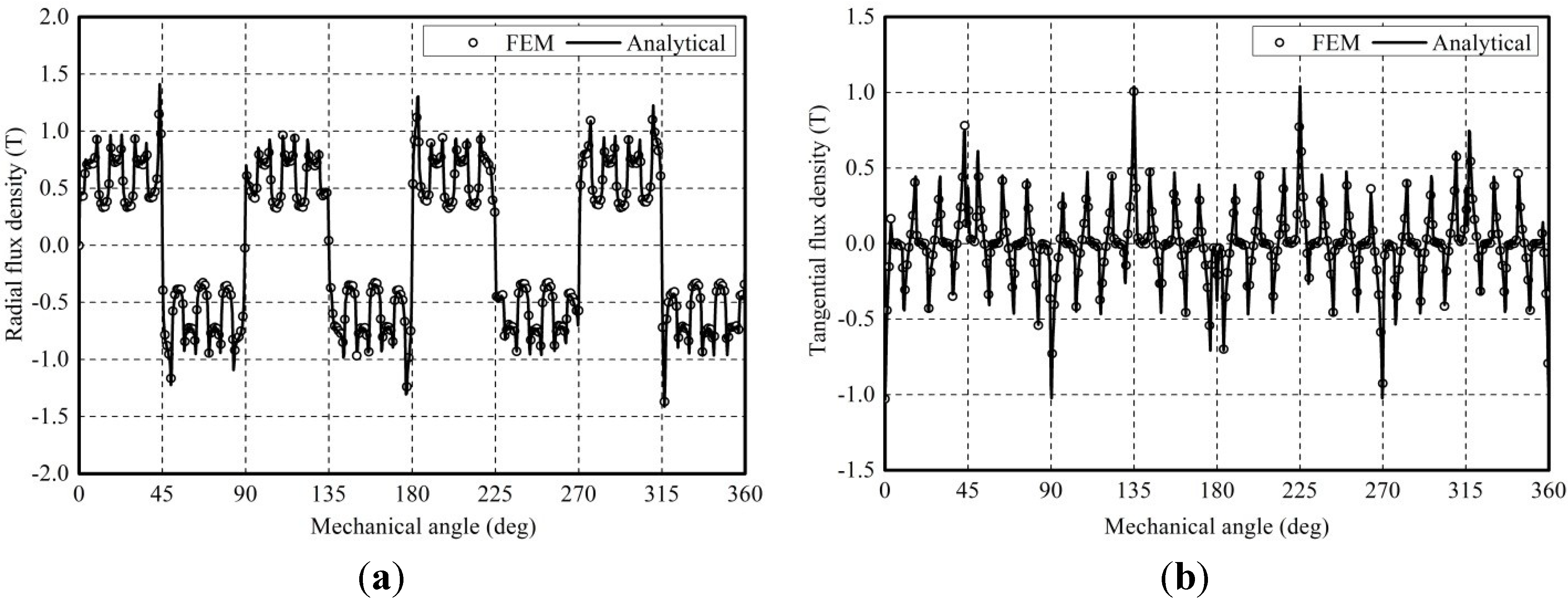
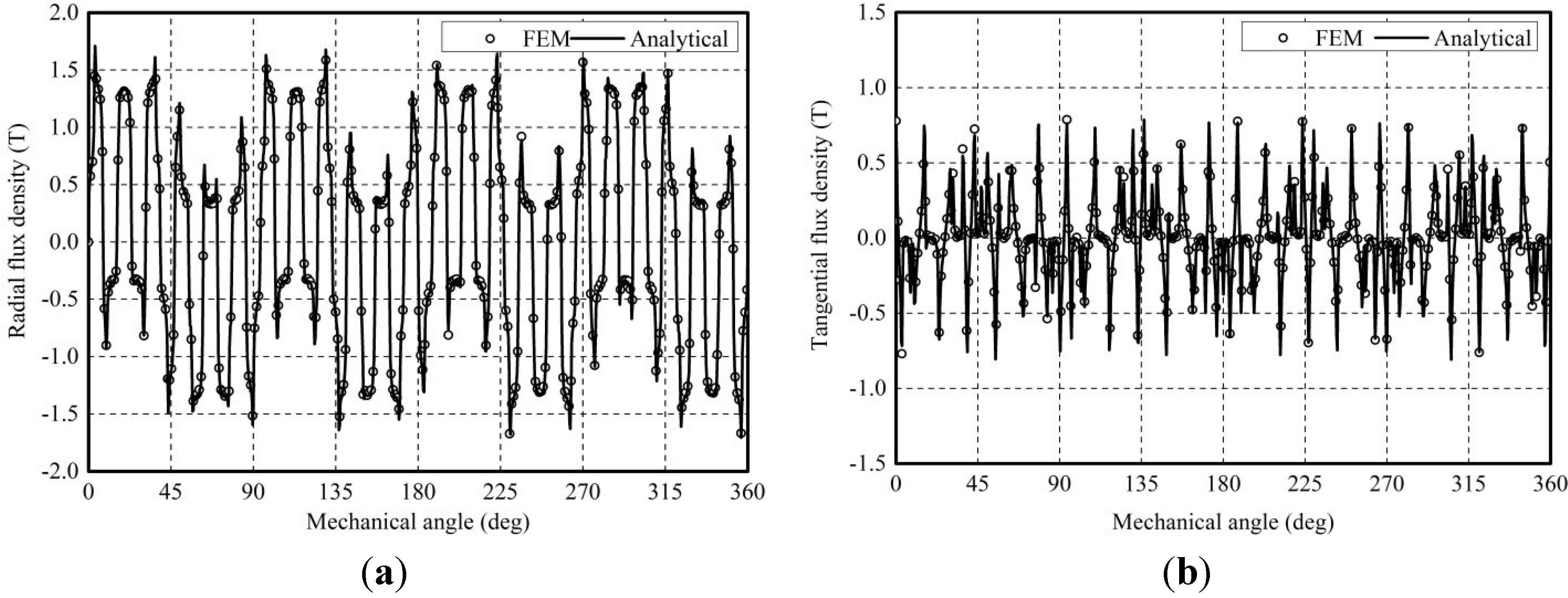
Figure 3 and
Figure 4 compare the analytically and numerically calculated distribution of the radial and tangential flux densities in two air-gaps, which are the function of the circumferential position θ. As can be seen, the analytical results have a good agreement with the FEM prediction.
Figure 3.
Comparison of the radial and tangential flux densities in the inner air-gap: (a) Radial flux density; (b) Tangential flux density.
Figure 3.
Comparison of the radial and tangential flux densities in the inner air-gap: (a) Radial flux density; (b) Tangential flux density.
Figure 4.
Comparison of the radial and tangential flux densities in the outer air-gap: (a) Radial flux density; (b) Tangential flux density.
Figure 4.
Comparison of the radial and tangential flux densities in the outer air-gap: (a) Radial flux density; (b) Tangential flux density.
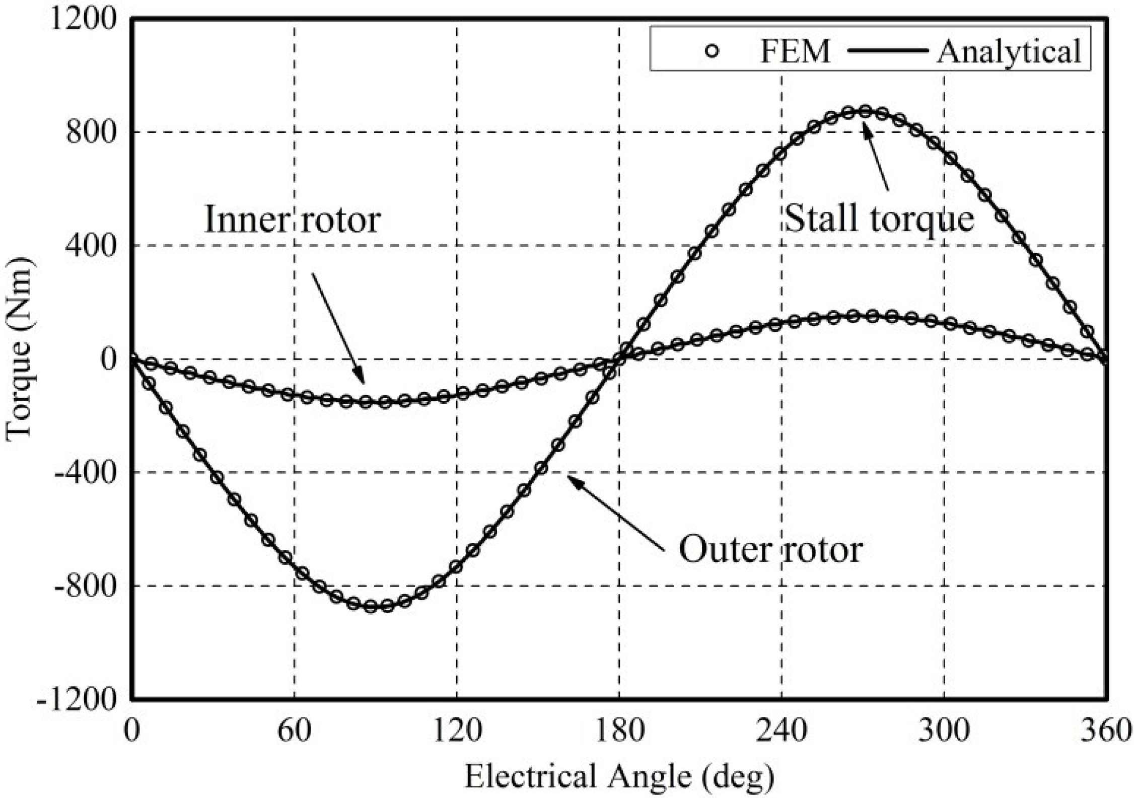
Additionally, by holding the outer rotor and modulation ring still and rotating the inner rotor, the magnetic torque
versus the inner rotor position can be obtained.
Figure 5 shows the static torque curves of the two rotors as the function of the inner rotor position obtained by the analytical and FEM method. The stall torques of the outer and inner rotors, as shown in
Figure 5, are 873 Nm and 151 Nm, respectively. The ratio of those two stall torques 873/151 = 5.78 agrees well with the ideal gear ratio
Gr = 23/4 = 5.75. As expected, there is an excellent agreement between the analytical and numerical calculations on the magnetic torque as well. Those comparisons show that the developed analytical model could be employed as a useful tool for analysis and optimization of the studied magnetic gear.
Figure 5.
Comparison of the radial and tangential flux densities in the outer air-gap.
Figure 5.
Comparison of the radial and tangential flux densities in the outer air-gap.
4. Impacts of the Design Parameters on Torque Capability
On the basis of the developed analytical expression for the magnetic torque, the impacts of the design parameters on the torque capability could be studied. In this paper, the stall torque of the outer rotor, which is located at the maximum point of the outer rotor torque curve in
Figure 5, is used to characterize the torque capability of the studied magnetic gear. As the outer diameter and length of the magnetic gear are fixed, the design parameters that influence the torque capability would be the PM pole-pair combination
po/
pi, the pole-pieces geometry τ
m/τ
p and τ
l/τ
p, the two PM rings thicknesses
to and
ti, and the two air-gap lengths δ
o and δ
i.
4.1. PM Pole-Pair Combination
According to Equation (3), there are a lot of possible combinations of
po and
pi, which give a gear ratio around 5.5:1. However, the study in [
9] has shown that some unreasonable combinations may cause a significant cogging torque, which is better to be excluded from the potential pole-pair combinations. A cogging torque factor was defined in [
21], to indicate the level of the cogging torque. Similarly, the corresponding cogging torque factors of the outer and inner rotors,
cfo and
cfi, could be given by:
where
Nco is the smallest common multiple of 2
po and
Ns; and
Nci is the smallest common multiple of 2
pi and
Ns.
The smaller cogging torque factor implies a smaller cogging torque. According to Equations (31) and (32), if one of
po and
pi is even, the other one should be odd, and vice versa. Based on this, larger
Nco and
Nci and lower cogging torque factors could be obtained. This rule is applied in the selection of the candidate combinations of
po and
pi, which are given in
Table 2. Since a large pole-pair number will lead to a great loss in PMs and ferromagnetic material, the PM pole-pair combinations are selected no greater than 28/5. The corresponding stall torques derived from the developed analytical model and FEM, and the PM consumptions are also included in
Table 2.
Table 2.
Possible PM pole-pair combinations.
Table 2.
Possible PM pole-pair combinations.
| PM pole-pair combination po/pi | Gear ratio Gr | Stall torque (Analytical) | Stall torque (FEM) | PM Consumption |
|---|
| 11/2 | 5.5 | 496 Nm | 489 Nm | 6.85 kg |
| 16/3 | 5.33 | 715 Nm | 704 Nm | 7.44 kg |
| 21/4 | 5.25 | 837 Nm | 826 Nm | 7.78 kg |
| 23/4 | 5.75 | 873 Nm | 864 Nm | 7.87 kg |
| 26/5 | 5.2 | 950 Nm | 938 Nm | 8.01 kg |
| 28/5 | 5.6 | 973 Nm | 958 Nm | 8.07 kg |
As can be seen, if the gear ratio is kept around 5.5:1, the stall torque changes a lot with varying po and pi. Due to the non-linearity of FEM model, the stall torque obtained from FEM is slightly lower than that from the developed analytical method. In the case of po/pi=11/2, the analytical stall torque is only 496 Nm. With the increase of po and pi, the stall torque increases rapidly first and then saturates at a certain level. As po and pi increase, the thickness of outer yoke and τl would decrease correspondingly, leading to a raise of the PM consumption and a resultant higher stall torque. However, the growth of the stall torque would not be so significant when po and pi reach to a certain level. From the above analysis, it is found that larger PM pole-pair number is preferred for a given gear ratio. However, the torsional stiffness of the pole-piece structure, the cost of PMs and iron loss would impose restrictions on the selection of po and pi.
4.2. Geometry of the Pole-Pieces
The pole-piece is scaled by τ
m/τ
p together with τ
l/τ
p in this paper.
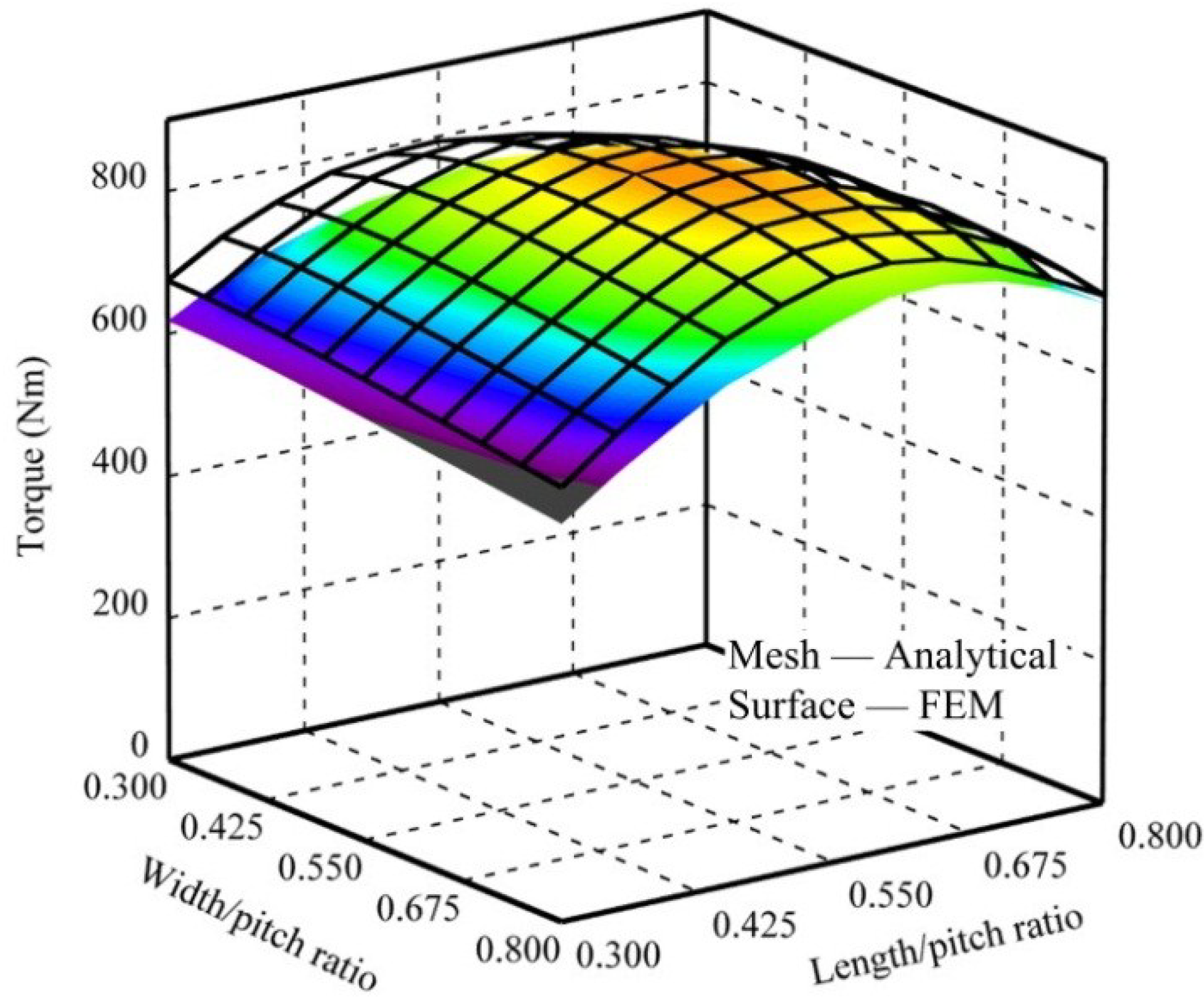
Figure 6 shows the evolution of the torque as a function of τ
m/τ
p and τ
l/τ
p varying from 0.3 to 0.8, while the other design parameters are the same as those in
Table 1. The profile of
Figure 6 looks like a dome, and the maximum torque 897 Nm is achieved at around τ
m/τ
p = 0.54 and τ
l/τ
p = 0.48.
Figure 6.
Torque capability with varying the geometry of pole-pieces.
Figure 6.
Torque capability with varying the geometry of pole-pieces.
The above behavior can be explained in terms of the magnetic path and magnetic reluctance. As known, if τ
m/τ
p is too small, the space between the outer and inner PM rings would be mainly filled with the air, whose permeability is very small and this leads to high reluctances. This will induce low flux densities in the two air-gaps and an inferior torque capability. Conversely, if the value of τ
m/τ
p is high enough, a substantial flux leakage would be produced which may close between the pole-pieces and adjacent magnets on the same rotor through only one-side air-gap. Hence, the torque would have a downward tendency as τ
m/τ
p exceeds 0.6, as shown in
Figure 6. Next, when τ
l/τ
p is kept small, the radial reluctances with and without pole-pieces are almost the same, which implies the modulation effect of the pole-pieces ring is quite poor. With the growth of τ
l/τ
p, the difference between the radial reluctances with and without pole-piece becomes more apparent, which could enhance the modulation effect. Furthermore, for a given
Dm, a large τ
l/τ
p would also decrease the volume of the inner PMs when
ti is fixed, which may bring the torque capability down in turn.
As the analytical model does not account for the saturation effect of the pole-pieces, the analytically calculated torque will be slightly higher than that calculated by FEM when the magnetic saturation takes place in the pole-pieces, as τm/τp or τl/τp is small. When the value of τm/τp is high, the flux linkage between pole-piece and adjacent magnets will be big enough to saturate the pole-pieces, which also makes the analytical results greater than the FEM results.
Clearly, the geometry of the pole-pieces plays a major role in the torque capability of the studied magnetic gear. It is better to set τm/τp and τl/τp around 0.5, to control the magnetic reluctance and flux leakage within a reasonable range.
4.3. PM Thickness
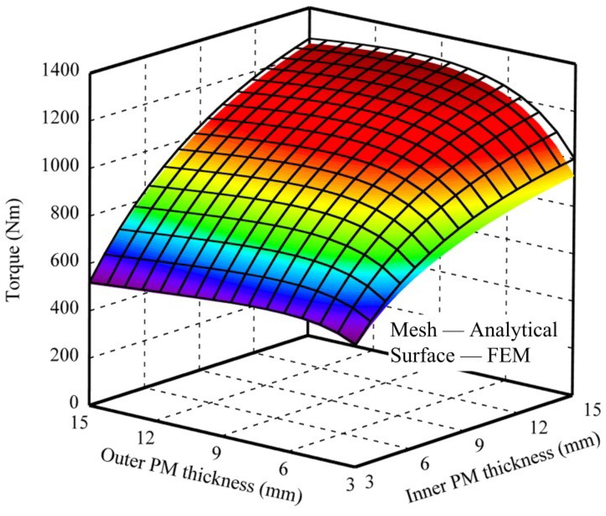
The impacts of
to and
ti on torque are shown in
Figure 7, which is obtained by scanning
to and
ti from 3 mm to 15 mm, while making other design parameters, namely
Dm,
L,
po/
pi, τ
m/τ
p, τ
l/τ
p, δ
o and δ
i , be in accordance with those in
Table 1. The analytical and FEM results have a good agreement except in the range that the
ti or
to is thick enough to saturate the magnetic field, as shown in
Figure 7.
Several important observations from
Figure 7 could be summarized as follows: first of all, increasing the PM consumption will generally benefit the torque capability of the magnetic gear; secondly, the torque capability of the magnetic gear is more sensitive to the inner PM ring than the outer PM ring, because the inner PM ring tends to make a better improvement on torque capability than outer PM ring with the same increase on thickness, as shown in
Figure 7; thirdly, it is interesting to note that as
to increases, the torque will raise quickly at first and then goes down slightly. This is because increasing
to while remaining other parameters unchanged will result in a bigger outer PM consumption, but reduce the inner PM consumption. Although the total PM consumption rises, the torque drops because the inner PM ring plays a more important role in the torque production. Therefore, increasing the PM thickness may not always benefit the torque capability of the magnetic gear, but reduce the cost effectiveness.
Figure 7.
Torque capability with varying PM thicknesses.
Figure 7.
Torque capability with varying PM thicknesses.
4.4. Air-Gap Length
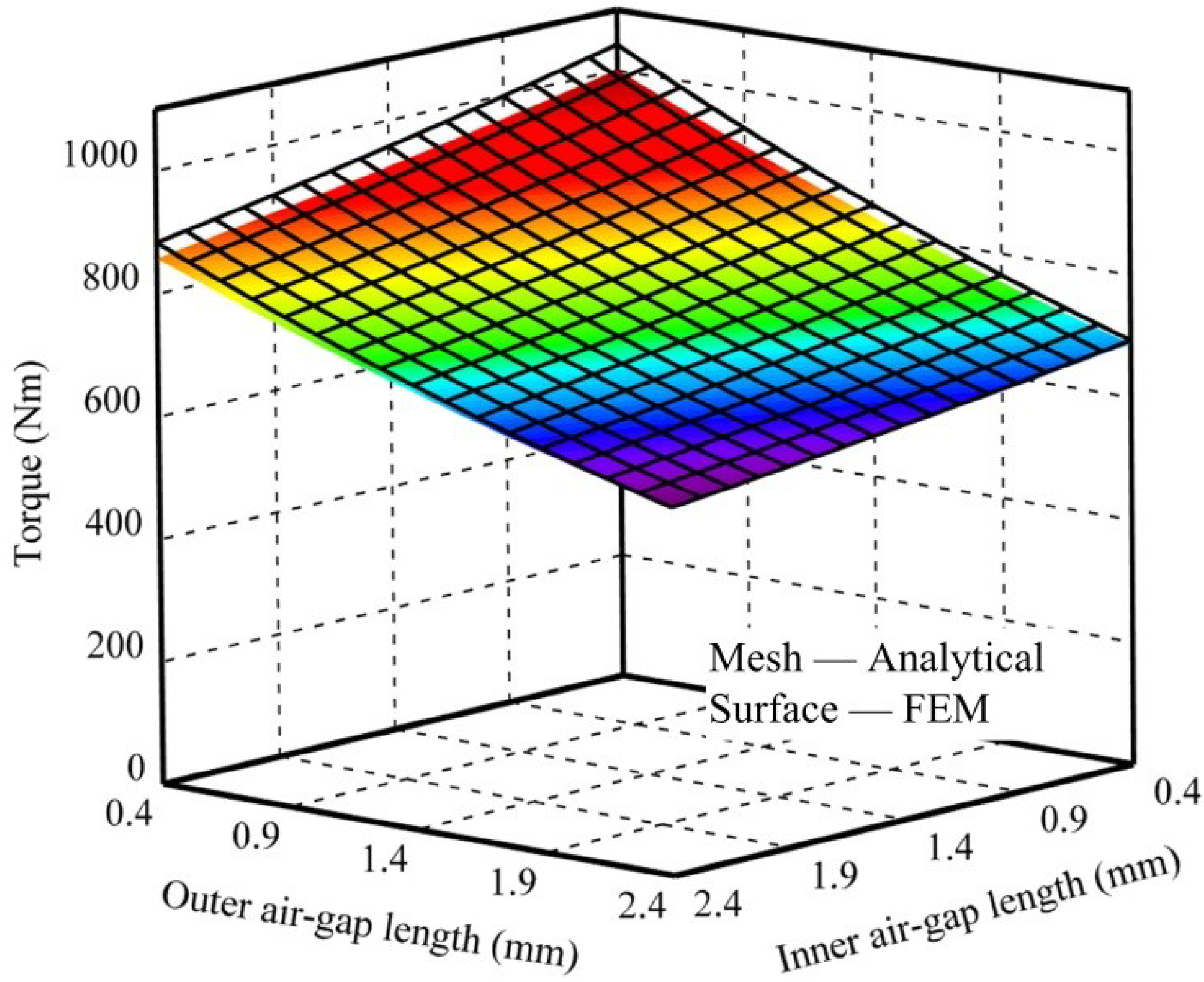
The profile of the torque with varying δ
o and δ
i is shown in
Figure 8, where could be observed that the increasing δ
o and δ
i will linearly decrease the torque, mainly due to the increase of the air-gap reluctance. Similarly, the analytical and FEM results have a good agreement in most area except the area where the δ
o or δ
i is too small. And it is important to note that the levels of influence on the torque capability by the two air-gaps are different. By keeping δ
o = 0.4 mm and changing δ
i from 0.4 mm to 2.4 mm, the produced torque will undergo a downsizing from 1,043 Nm to 883 Nm. In contrast, keeping δ
i at 0.4 mm and changing δ
o from 0.4 mm to 2.4 mm, the produced torque dramatically decreases from 1043 Nm to 692 Nm. The reason is that
po is always close to
Ns. If δ
o is big, there is more flux circuiting between outer PMs and modulation pole-pieces instead of passing through the both air-gaps. These flux leakages will not contribute to the torque production. Therefore, the outer air-gap length plays a more important role in the torque production than the inner air-gap.
Figure 8.
Torque capability with varying lengths of two air-gaps.
Figure 8.
Torque capability with varying lengths of two air-gaps.
Although the two air-gap lengths are always desired to be as small as possible with consideration of the manufacturing tolerance, it is still better to be aware that the length of the outer air-gap is more important for the torque capability than the inner air-gap when designing a coaxial PM magnetic gear.
5. Design Optimization
Section 4 has investigated the impacts of the design parameters on the torque capability of the coaxial magnetic gear individually and with partial coupling. However, those studies are not enough to optimize the magnetic gear without a comprehensive knowledge of the cross impact between different design parameters. Hence, it is necessary to investigate all of key parameters simultaneously. However, it is not desired to maximize the torque capability without the consideration of the material cost, since the cost is a sensitive factor for its industrial application. Consequently, the compromise between the torque capability and the material cost is defined as a multi-objective optimization problem in this section. The PSO algorithm is then employed to accomplish a set of optimal solutions.
5.2. Flow of the Optimization
The PSO algorithm is a heuristic and stochastic searching methodology that is capable of achieving a reliable and fast convergence to find the global optimum [
24]. The process of PSO method relies on a population of particles traveling through a multi-dimensional searching space. The property of each particle is described by two variables,
i.e., position and velocity, which are updated continuously to emulate the tendency to learn the success of other individuals in the population [
25]. Hence, the trajectory of each particle is gracefully approaching toward the global best position.
When it comes to the optimization for the studied magnetic gear, the position of the particles can be expressed by design parameters, as shown in Equation (33), forming a seven-dimensional searching space.
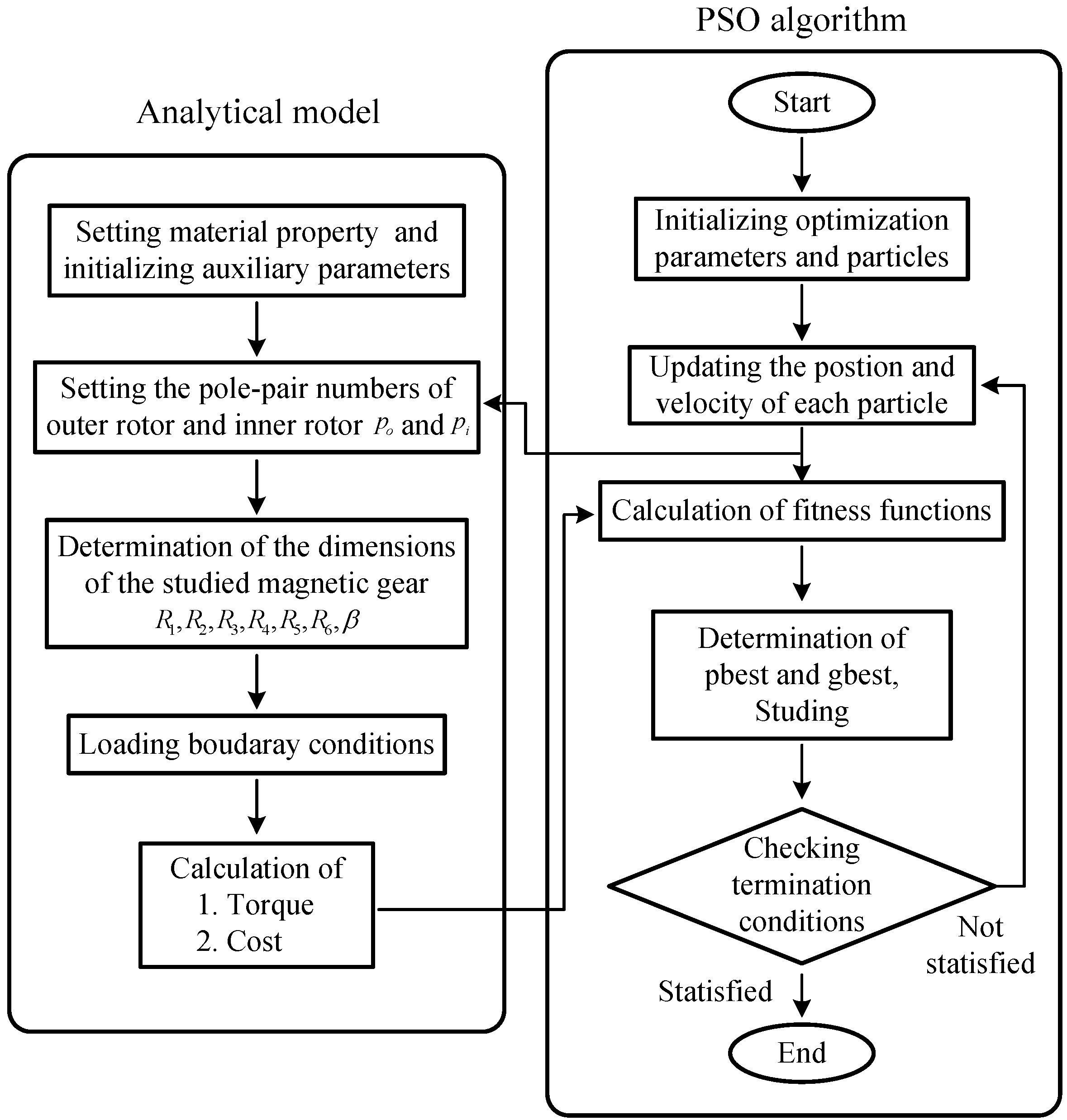
Figure 9 shows the flow chart of the PSO algorithm as well as its connection with the developed analytical model of the studied magnetic gear. First, a population of 30 particles is initialized, and these particles are evenly distributed in the seven-dimensional space. Velocities of all particles are initialized to be zero. The initial positional information of each particle, which represents a set of design parameters, is used as the inputs for the analytical model, as shown in
Figure 9. In the analytical model, setting the pole-pair numbers for two PM rings and determining the dimensions of the magnetic gear occur in sequence. By loading the boundary conditions, the corresponding torque and cost are calculated and then transferred to the PSO algorithm. Next, the fitness of the each particle is determined by taking into account the weight factors of torque and cost,
wt and
wc, through fitness function. After going through the above processes, the local best value (pbest) of each particle and global best value (gbest) in this population are thereby obtained or updated through comparisons. The inferior particles will study the properties of the better ones, and then they can pursue the optimal particles to get improved by refreshing their velocity and position. Those procedures continue and repeat until the termination condition is satisfied. By the end of design optimization, a global optimal solution with specific emphases on torque capability and cost can be accomplished.
Figure 9.
Flow chart of the design optimization algorithm.
Figure 9.
Flow chart of the design optimization algorithm.
5.3. Results
Different applications of the magnetic gear have different requirements on the performance and cost. For example, in aerospace and military fields, torque capability is paid more attention to, while industrial applications are more sensitive to the cost factor. Therefore, optimizations with different emphases on torque capability and material cost are conducted in this paper.
Table 3 compares the torque capability, PM consumption, active steel consumption, total material cost, torque density (torque per unit volume), and torque per unit PM mass between the initial design and five optimal designs obtained under different weight factors on the torque capability and material cost.
Table 3.
Optimization results.
Table 3.
Optimization results.
| Symbol | Quantity | Initial design | Design 1 wt = 1 wc = 0 | Design 2 wt = 0.7 wc = 0.3 | Design 3 wt = 0.5 wc = 0.5 | Design 4 wt = 0.3 wc = 0.7 | Design 5 wt = 0.1 wc = 0.9 |
|---|
| po/pi | PM pole-pair combination | 23/4 | 28/5 | 28/5 | 28/5 | 28/5 | 28/5 |
| τm/τp | pole-piece width/pole pitch ratio | 0.5 | 0.44 | 0.47 | 0.55 | 0.52 | 0.51 |
| τl/τp | pole-piece length/pole pitch ratio | 0.5 | 0.39 | 0.41 | 0.49 | 0.55 | 0.8 |
| to | thickness of outer PM ring | 6 mm | 10 mm | 6.7 mm | 4.0 mm | 3 mm | 3 mm |
| ti | thickness of inner PM ring | 6 mm | 10 mm | 10 mm | 7.9 mm | 3.6 mm | 3 mm |
| δo | length of outer air-gap | 1 mm | 1 mm | 1 mm | 1 mm | 1 mm | 1 mm |
| δi | length of inner air-gap | 1 mm | 1 mm | 1 mm | 1 mm | 1 mm | 1 mm |
| T | torque capability | 873 Nm | 1264 Nm | 1224 Nm | 1001 Nm | 653 Nm | 554 Nm |
| TFEM | torque validated by FEM | 864 Nm | 1230 | 1223 Nm | 996 Nm | 636 Nm | 524 Nm |
| Mpm | PM consumption | 7.9 kg | 13.2 kg | 10.6 kg | 7.8 kg | 4.5 kg | 4.0 kg |
| Mla | active steel consumption | 35.2 kg | 28.1 kg | 29.6 kg | 31.6 kg | 32.8 kg | 33.0 kg |
| C | total material cost | $385 | $584 | $484 | $377 | $244 | $225 |
| dt | torque density | 108 kNm/m3 | 157 kNm/m3 | 152 kNm/m3 | 124 kNm/m3 | 81 kNm/m3 | 69 kNm/m3 |
| dpm | torque/PM consumption | 110.9 Nm/kg | 96 Nm/kg | 115 Nm/kg | 128 Nm/kg | 145 Nm/kg | 138 Nm/kg |
It is evident that the torque performance and cost normally conflict with each other. If the optimization is only aimed at maximizing the torque, as defined in Design 1, wt = 1, wc = 0, the highest torque capability of 1264 Nm and torque density of 157 kNm/m3 can be achieved, respectively. Meanwhile, the material cost, which is up to $584, is also the highest. It is important to note that the best torque capability is achieved by increasing the consumption of PMs, resulting in the lowest torque per unit PM mass of 96 Nm/kg. Conversely, Design 5 regards the material cost as the most important factor, by setting the weight factors of torque and cost to 0.1 and 0.9, respectively. Thus, the thicknesses of the outer and inner PM rings both drop down to the lower limit at 3 mm. In this case, although the material cost is greatly reduced, the torque capability is also significantly reduced, resulting in the lowest torque density at 69 kNm/m3. Design 3 is accomplished with the purpose of balancing the weight of the torque capability and cost. A torque density of 124 kNm/m3 and a torque per PM consumption of 128 Nm/kg could be achieved. Despite of nearly the same consumption of PMs, the torque capability in Design 3 exceeds 15 % of that in the initial design, which is a significant improvement. Design 2 and Design 4 have the opposite weight factors on torque and cost, so that they possess the reciprocal performances. Design 2 achieves the second highest torque capability of 1224 Nm and torque density of 152 kNm/m3, while Design 4 accomplishes the second lowest material cost of $244 and the best torque per unit PM mass of 145 Nm/kg.
As expected, the lengths of the outer and inner air-gaps are made as short as possible in all cases. Furthermore, as shown in the foregoing analysis, higher values of
po and
pi could increase the volume of PMs and then result in a higher torque, which may explain why all optimized PM pole-pair combinations are 28/5. As shown in
Table 3, the optimized torque has been validated by FEM. For uniformity, the torque density and torque/PM consumption presented in
Table 3 are derived according to the torque calculated by analytical model.
6. Conclusions
This paper has developed an analytical model for the coaxial surface-mounted PM magnetic gear, which presents a good agreement with the corresponding FEM model. The developed analytical method, which allows the torque capability and material cost to be expressed as a function of design parameters, is very useful for evaluating the influence of the key design parameters on the magnetic gear performance, and also for performing optimizations of the studied magnetic gear. Some significant observations could be concluded as follows: (1) for a given gear ratio, larger pole-pairs of the two PM rings are preferred; (2) it is better to set the pole-piece width/pole pitch ratio and length/pitch ratio to be around 0.5; (3) the inner PM thickness plays a more important role in the torque capability than the outer PM thickness; (4) the torque capability is more sensitive to the outer air-gap length than the inner air-gap length.
Global optimizations, which could take into account all design parameters simultaneously by using PSO, have been carried out in this paper. The torque capability and material cost have been set as the optimization objectives. Different weight factors have been imposed on the two objectives so that more attention can be placed on one or another. The optimization results have shown that the torque capability conflicts with the material cost. The highest torque density of 157 kNm/m3 could be achieved if the consideration is focused on the torque capability only, while the highest torque per PM consumption could be improved to 145 Nm/kg by taking the material cost into account. By synthesizing the torque capability and material cost, a 124 kNm/m3 of torque density and a 128 Nm/kg of torque per PM consumption could be achieved simultaneously by the optimal design. Consequently, this paper provides a valuable method to implement the optimal design of the coaxial PM magnetic gear.


