Article

An Active Power Sharing Method among Distributed Energy Sources in an Islanded Series Micro-Grid

College of Electrical Engineering and Information Engineering, Lanzhou University of Technology, Lanzhou 730050, Gansu, China
*
Author to whom correspondence should be addressed.
Energies 2014, 7(12), 7878-7892; https://doi.org/10.3390/en7127878
Submission received: 16 July 2014 / Revised: 29 October 2014 / Accepted: 18 November 2014 / Published: 26 November 2014

Abstract

:
Active power-sharing among distributed energy sources (DESs) is not only an important way to realize optimal operation of micro-grids, but also the key to maintaining stability for islanded operation. Due to the unique configuration of series micro-grids (SMGs), the power-sharing method adopted in an ordinary AC, DC, and hybrid AC/DC system cannot be directly applied into SMGs. Power-sharing in one SMG with multiple DESs involves two aspects. On the one hand, capacitor voltage stability based on an energy storage system (ESS) in the DC link must be complemented. Actually, this is a problem of power allocation between the generating unit and the ESS in the DES; an extensively researched, similar problem has been grid-off distributed power generation, for which there are good solutions. On the other hand, power-sharing among DESs should be considered to optimize the operation of a series micro-grid. In this paper, a novel method combining master control with auxiliary control is proposed. Master action of a quasi-proportional resonant controller is responsible for stability of the islanded SMG; auxiliary action based on state of charge (SOC) realizes coordinated allocation of load power among the source. At the same time, it is important to ensure that the auxiliary control does not influence the master action.

Graphical Abstract

1. Introduction

Power generating units, energy storage systems, control and protection units, loads and converters are connected together via a certain configuration, which forms an autonomous power distribution network, i.e., a micro-grid [1,2]. They are regarded as the new underlying structures of smart grids in the engineering and academic fields. A new type of system called series micro-grids (SMGs), shown in Figure 1, can fundamentally resolve the main problems existing in ordinary AC, DC, and hybrid AC/DC micro-grids such as circulation, harmonics, complexity of stability control, and so on, or make it simpler to solve some of these problems. Additionally, SMGs have high power quality and security [3,4]. In these references, the output characteristics and outstanding advantages of one SMG have been comprehensively analyzed, and the main problems, which need to be solved, have been pointed out. The influence of photovoltaic (PV) characteristics on the voltage stability of an islanded single-phase system was identified as a tricky issue. Moreover, the group has expanded upon other issues, including small signal stability analysis, the accurate control of DC link voltage, based on a hybrid energy storage system (ESS) and equivalent load model on the DC side with inverter units connected in series.
The islanded operation of SMGs is the foundation for improving the reliability of power supply for local loads, and coordinated allocation of load power is an important means of achieving optimal operation in this mode. Power-sharing of a series micro-grid mainly involves two aspects: the first one refers to a generating unit and ESS in one random distributed energy source, and the other to the hybrid energy storage system itself. The goal is to maintain the inner power balance of the source or optimize the charging/discharging process. The second one is completed among distributed energy sources (DES), such as wind turbines, photovoltaic (PV) cells, diesel generators, micro gas turbines, etc., with the purpose of achieving the optimal operation of a micro-grid. Internal power balance of a random source based on one ESS can be implemented by switching operation modes or with a resistance unloading method, when local meteorological conditions are excessive. Although those methods are usually adopted in off-grid distributed power generation, they may, unfortunately, result in primary and secondary energy waste in SMGs [5,6]. If the balance is maintained by the coordinated allocation of load power among DESs, the exploitation efficiency of renewable energy would be improved and the operation cost could be reduced.
Some scholars have researched similar series systems and made many achievements. The cascaded H-bridge inverter-based PV grid-connection power system has been researched for a long time. This is the first time that a specific structure with multiple inverter units connected in series has been applied in the field of renewable energy power generation. Multilevel converters, including the cascaded H-bridge inverters, were mentioned in single-phase grid-connection PV systems in 1999, and their many advantages were noted, such as the sinusoidal waveform of output voltage with low harmonic distortion or attractively meeting the need of several sources on the DC side of the converter by PV cells [7]. The cascaded multilevel converter was discussed in applications of renewable energy systems in 2002, also in reference to PV power systems [8,9]. The research results in this field have focused on grid current control, including via traditional linear methods [10,11] and modern intelligent algorithms [12,13], which did not extend to the power-sharing problem for an islanded series micro-grid. Compared with SMGs, the cascaded systems have many drawbacks, including a single energy source, an un-switchable operation mode, and low reliability.
Power generation based on the cascaded H-bridge inverter with PV cells/fuel cells/battery hybrids on each DC side are seen as subsystems, which are applied to a medium voltage micro-grid to improve its power quality under an unbalanced and nonlinear load [14,15]. In these literature, power allocation among PV cells, fuel cells, and batteries, together located in the DC link of one inverter unit has been considered, but power-sharing among the hybrid generations has not been absorbed. Again, the subsystems in the medium voltage network are indeed in parallel operation. The problem of active power-sharing has been addressed by using cascade static synchronous compensators in order to maintain capacitor voltage balance. In [16], the DC-bus voltage balance has been achieved by directly varying the modulation index of each H-bridge. This method which is easy to implement in multi-loop feedback control needs certain improvement for one SMG because of its complicated energy structure and unpredictable disturbances.
This paper is organized as follows: in the next section the configuration of the series micro-grid is outlined. In Section 3, the principles and methods of active power-sharing are investigated in detail. A power-sharing strategy based on the state of charge (SOC) of an ultra-capacitor ESS is given in Section 4, and Section 5 presents simulation results and discussions. Finally, Section 6 summarizes the significant findings arising from this work and suggests future research topics.

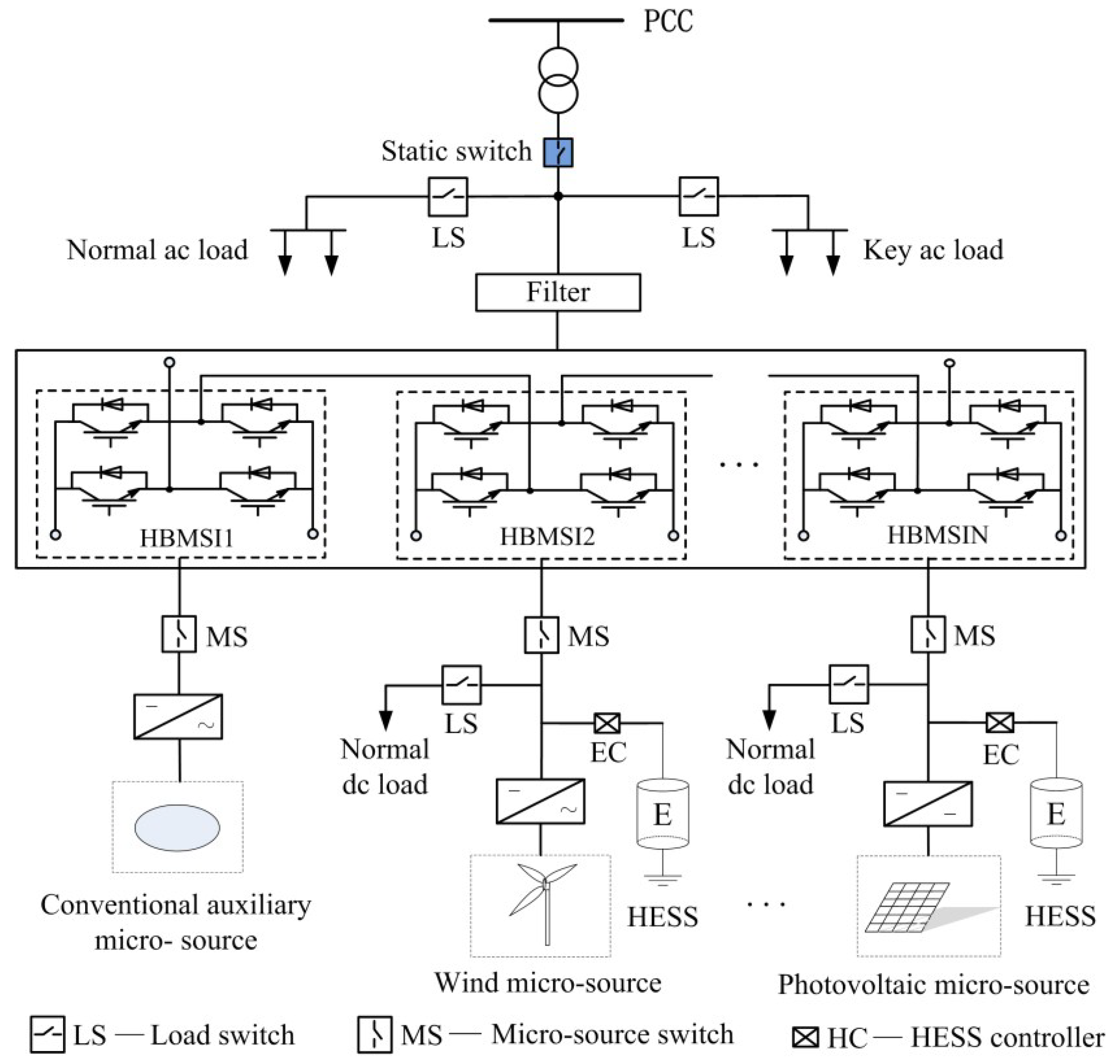
2. Series Micro-Grid System

2.1. Configuration of the System

The configuration of one series micro-grid is shown in Figure 1. To simplify the integration procedures, DES should be classified into either AC-type or DC-type, according to the primary output power form of the generating unit. Micro gas turbines (MGT), diesel generators, and direct-drive permanent-magnet synchronous and doubly-fed asynchronous wind power generation all belong to AC DES. PV cells and fuel cell power generation are involved in DC DES. They can be also be divided into two categories, namely main and complementary source, according to their status in SMGs. Renewable and clean DES basically appertain to the former (e.g., such as wind generation, PV and fuel cells), while MGT and diesel generators belong to the latter.
Figure 1 illustrates a single-phase SMG. Isolated power generating units with corresponding AC/DC or DC/DC conversion are finally linked by H-bridge micro-source inverters (HBMSIs) connected in series. The output voltage of the inverters is superimposed and a multilevel voltage waveform of the series micro-grid eventually forms under carrier phase shifted-SPWM (CPS-SPWM). AC voltage with expected amplitude and frequency can be acquired after simple filtering. One three-phase system can be easily comprised of three symmetrical single-phase SMGs. The number of DESs can be flexibly adjusted to meet the different requirements of voltage grade for connection with a utility grid. SMGs are suitable for forming a power network with multiple DESs located nearby. Moreover, SMGs can also be applied as capable subsystems to a medium voltage micro-grid to provide power support and improve its power quality.
Figure 1. Configuration of one series micro-grid.
Energies 07 07878 g001

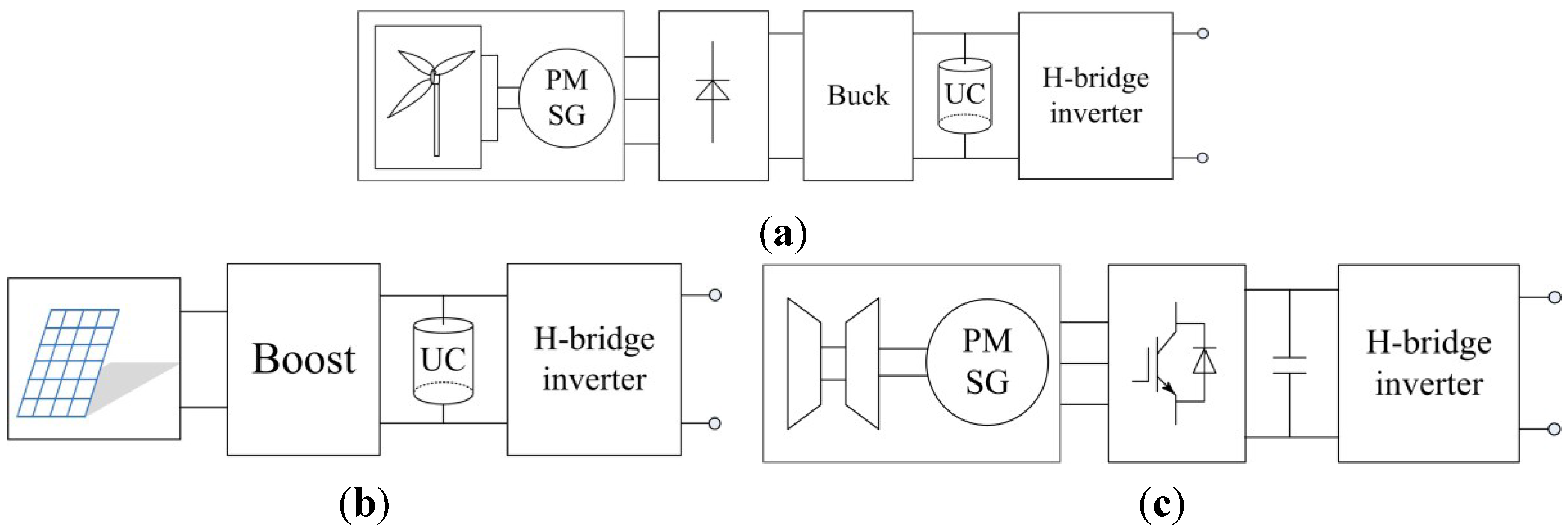
2.2. Converter Architecture of Distributed Energy Sources

In this study, the single-phase SMG has three DES, including wind, solar and MGT generation. Their simplified architectures are shown in Figure 2.
Figure 2. Topology of the distributed energy sources (DES). (a) Wind DES; (b) solar DES; (c) micro gas turbine DES.
Energies 07 07878 g002
The MGT adjusts the output power according to the DC link voltage change to meet load demand, so as to keep the voltage stable. Wind and solar DES operate in MPPT mode by regulating duty cycle of the DC converters. Ultra-capacitor ESS installed in DC link of the random source is responsible for flicker mitigation and maintains the inner power balance [17]. SOCx (x = w, s, representing the ultra-capacitor unit in wind and solar DES, respectively) is monitored in the operation process; charging is stopped when SOCx > SOCmax, and discharging is confined when SOCx > SOCmin.
If the output power of the renewable energy source is not reduced after discharging is limited, a voltage drop and voltage collapse may happen in the short term. However, if a random DES is still in the MPPT mode and maintains its precious output after confined charging, the power generated will be greater than that consumed by an equivalent load. This is bound to cause surging voltage, which is a serious threat to system security.
Switching operation mode and resistance unloading methods are usually applied to off-grid distributed generation. However, if the approaches are still used for random source in series micro-grids, this will not enable the hybrid features between wind and solar source, causing energy waste. Maximizing the use of clean energy is aspired to in this work, and insufficiencies shall be compensated for by the micro gas turbine.

3. Principle and Implementation Method of Power-Sharing

3.1. Power-Sharing Principle

Assuming that the reference value u dc i * (i = 1, 2, 3) of each dc link voltage udci in different DESs are equal, i.e., u dc i * u dc * , such an outcome of udci u dc * will occur under effective control of energy storage systems and regulation of the micro gas turbine itself. The output voltage harmonic content of the inverter-link composed of three cells connected in series is low under the master control, so the fundamental component uAN under sinusoidal modulation is mainly considered:
u AN = 2 U AN   sin ( ω s t )
where UAN is a nominal rms of uAN, ωs is the angular frequency of the modulation signal.
The expression of inductance current iL under linear conditions can be assumed by the next formula:
i L = 2 I L   sin ( ω s t φ )
where IL is the nominal rms of iL, φ is the phase angle between uAN and iL.
Under the sinusoidal condition, the output active power of the SMG is defined as follows:
P = U AN I L cos φ
AC side currents of each H-bridge inverter are all equal to the inductance current iL. In addition, uAN and dc voltage udci satisfy the following relation:
U AN = 1 2 ( m 1 u dc1 + m 2 u dc2 + m 3 u dc3 )
In Formula (4), mi is the modulation index of the ith (i = 1, 2, 3, respectively representing the wind, solar, and MGT) inverter unit. Further:
P = 1 2 ( m 1 u dc1 + m 2 u dc2 + m 3 u dc3 ) I L cos φ
The output active power Pi of ith inverter is equal to:
P i = 1 2 m i u dc * I L cos φ
Eventually, the ratio of active power can be obtained as follows:
P 1 : P 2 : P 3 = m 1 : m 2 : m 3
In the same way, the following reactive power formula can also be obtained:
Q 1 : Q 2 : Q 3 = m 1 : m 2 : m 3
It can be seen that power-sharing can be implemented by regulating the ratio of the modulation index among different inverter units under the linear load condition from Formulas (7) and (8).
Assume that the DC capacitor voltages of the DES are all equal to each other. When the output voltage harmonic content of the SMG under the CPS-SPWM modulating method is lower than for ordinary micro-grids; the series system has a unique advantage. However, the condition is still unknown when the ratio of the modulation index changes in this process. The details of analysis are shown in Figure 3, which shows the change trend of the total harmonic distortion (THD) of the output voltage of the inverter-link in the single-phase series micro-grid with three DES under different conditions. Ten discrete points of abscissa on the curve A1 in Figure 3a comply with the relations of m1 = 0.75 + 0.025 × d, m2 = 0.75 − 0.025 × d, here d = 0, 1, 2, …, 9, m3 = 0.75. The THD has increased with the enlargement of the modulation index ratio, but the increment does not show much variation; the biggest increment is less than 20%. The harmonic content of the output voltage of this series system is much lower than the single H-bridge inverter’s in the same case. Thus, SMG still has obvious advantages.
Figure 3. Curves of total harmonic distortion of output voltage. (a) Under situation of mi/mj; (b) Under situation opposite to (a); (c) Under situation of mi/mj and the others.
Energies 07 07878 g003
Curve A2 with m1 = 0.75 + 0.025 × d, m2 = 0.75, m3 = 0.75 − 0.025 × d; curve A3 with m1 = 0.75, m2 = 0.75 + 0.025 × d, m3 =0.75 − 0.025 × d, the corresponding THD of curve A2 and A3 are all different from A1, but the difference is very slight. However, the access to the abscissa of Figure 3b is opposite to that of Figure 3a, e.g., the curve B1 with m1 = 0.75 − 0.025 × d, m2 = 0.75 + 0.025 × d, m3 = 0.75, the THD of the latter is almost the same as the former’s. The curve C1 in Figure 3a has the constraint of m1 = m2 = 0.75 + 0.025 × d, m3 = 0.75 − 0.05 × d. As demonstrated by curve C2 with m1 = m3 and C3 of m2 = m3. The method of obtaining the other modulation index is similar to C1. Obviously, the THD of the output voltage is nearly the same as each situation from Figure 3. These results illustrate that the power-sharing strategy is feasible.

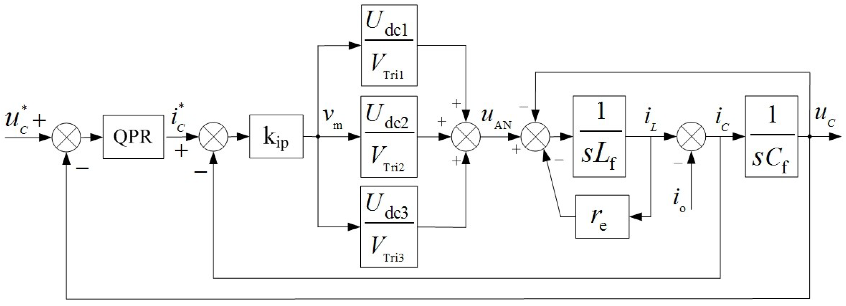
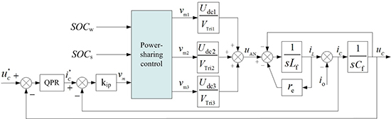
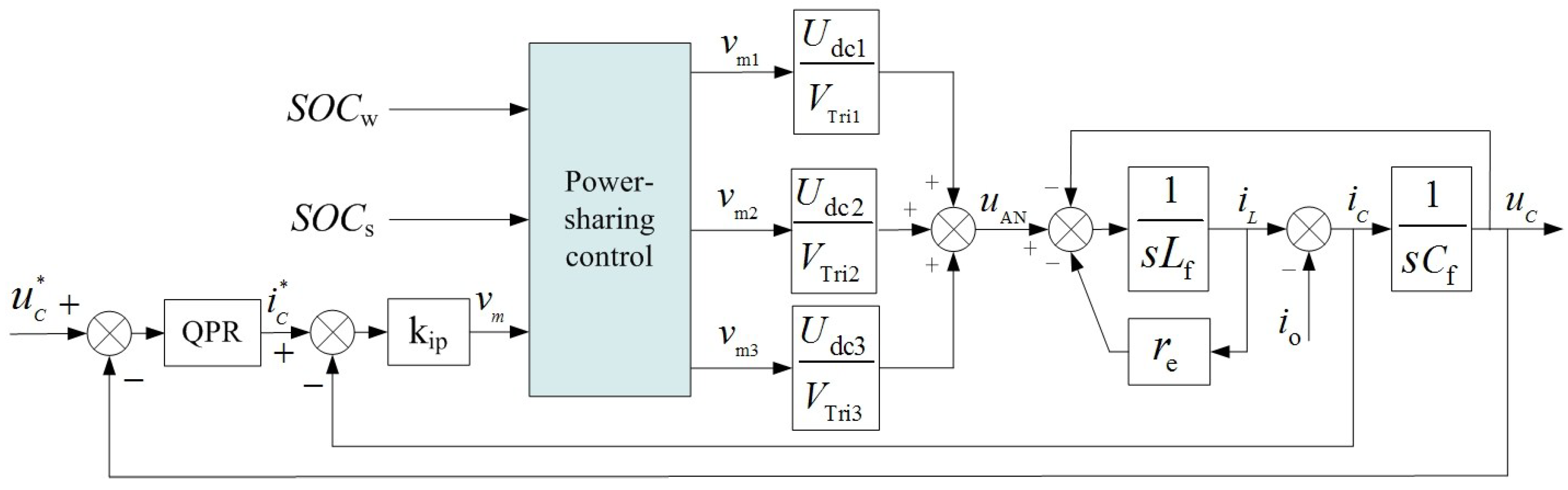
3.2. Power-Sharing Implementation Method via Inverter-Link Control

Stability control and power-sharing control are coupled and related to each other in SMGs. Rather than a common AC micro-grid with a decentralized control strategy, output voltage and frequency stability mainly depend on the main source with v/f control, and load power allocation is automatically accomplished via the different coefficients among multiple complementary sources, which all usually adopt droop control. Therefore, a composite method combining master control and auxiliary control is adopted to concurrently accomplish the voltage adjustment and power allocation for the islanded series systems in this paper. The main action is in charge of the stability, and the auxiliary action is used for realizing the coordinated allocation. Here, the method needs to satisfy two conditions: (a) the islanded system itself has to be stable under the master control; (b) auxiliary control does not result in a negative impact on the main action.

3.2.1. Master Control for System Stability

The quasi proportional resonant (QPR) controller has no gain-infinity at its resonant frequency. This controller can eliminate the static error of tracking a sinusoidal variable, which is difficult to solve by a PI regulator. The controller is adopted in a closed-loop control of capacitor voltage as a main function to realize high-precision tracking for the reference.
In addition, to improve the dynamic response and enhance the ability of resisting load disturbance, the inner loop control of the capacitive current is added. For equivalent block diagrams of the master control, as shown in Figure 4, the transfer function of the QPR controller is:
G ( s ) = k p + 2 k i ω c s s 2 + 2 ω c s + ω o 2
where kp is the proportional gain, ki is the integral coefficient, ωc is the cut-off frequency, and ωo is the resonant frequency.
In Figure 4, Udci (i = 1, 2, 3) is the state value of udci, uc is the capacitor voltage, ic is the capacitor current, io is the load current seen as an emergency, and VTrii is the amplitude of the triangular carrier wave (its value is usually equal to 1). Cf is the filter capacitor, re is the sum of equivalent resistances of the inductance, inverter units, and the line.
Figure 4. Master control block diagram of the inverter-link.
Energies 07 07878 g004
The output voltage transfer function of the inverter-link under the double-loop control is acquired according to Figure 4; the expression is as the follows:
u c ( s ) = G ( s ) k ip ( s ) K PWM u c * ( s ) ( r e + L f s ) i o L f C f s 2 + ( r e + k ip K PWM ) C f s + 1 + G ( s ) K PWM k ip
where KPWM = (Udc1+ Udc2+ Udc3)/VTrii, it can be said for the total modulation index.
The frequency characteristic of the output voltage loop gain function of the inverter-link can be obtained according to the parameters given in Table 1, as shown in Figure 5. It can be seen from the figure that the inverter-link has a high gain of 48 dB at the resonance frequency (50 Hz), which ensures the high tracking ability of the power frequency signal. At the same time, the phase margin of 43 deg indicates that the system has good dynamic response.
Figure 5. Bode diagram of the loop gain function of the inverter-link under double-loop control.
Energies 07 07878 g005

3.2.2. Auxiliary Control for Power-Sharing

The active power-sharing method is shown in Figure 6. The sharing signal ∆vmi with the same frequency and phase as vm is superimposed on this master control signal, which is produced by a closed-loop and which finally forms a new control signal, vmi. The actual modulation signals vmi are not equal to each other; thus, power-sharing among the micro sources can be accomplished.
Figure 6. Block diagram of the active power-sharing method.
Energies 07 07878 g006
The SOCx reflects the potential ability of output power from one source, so adjusting ∆vmi according to the SOCx can effectively make use of clean energy based on a scheduling strategy, and the insufficiencies can be satisfied by the micro gas turbine. Ultimately, the power-sharing method can be obtained for an islanded series micro-grid with three DES, as shown in Figure 7.
Figure 7. Control of the inverter-link with a power-sharing function.
Energies 07 07878 g007
The following analysis focuses on the influence of the auxiliary on master control. The state space average model of the inverter-link is established, and the transfer function of the equivalent duty ratio dab to output voltage uc is acquired as the following:
u c ( s ) d ab ( s ) = i = 1 3 u dc i L f C f s 2 + r e C f s + 1
where dab(s) is equal to vm when VTrii = 1.
The small variation d ^ i ab ( s ) of duty ratio dab(s) is obtained after artificially introducing the auxiliary function. So, voltage variation u ^ c ( s ) caused by auxiliary control (not master function with closed-loop) is acquired via the perturbation method, as shown by Formula (12):
u ^ c ( s ) = i = 1 3 d ^ i ab ( s ) U dc i L f C f s 2 + r e C f s + 1
The DC link voltage maintains high stability, i.e., U dc i = u dc * . As long as the control system meets the following constraint condition, as shown in Formula (13), the negative influence of the auxiliary control on master function can be avoided:
i = 1 3 d ^ i ab ( s ) = 0
Under the closed-loop control, Formula (13) is the same as the following in this system.
Δ v m1 ( s ) + Δ v m2 ( s ) + Δ v m3 ( s ) = 0

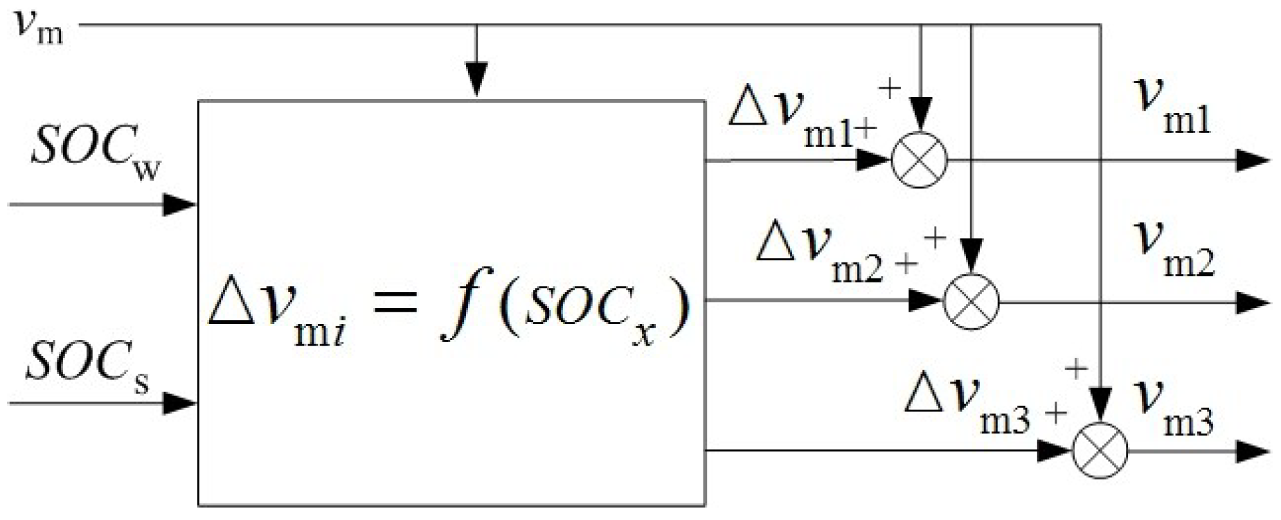
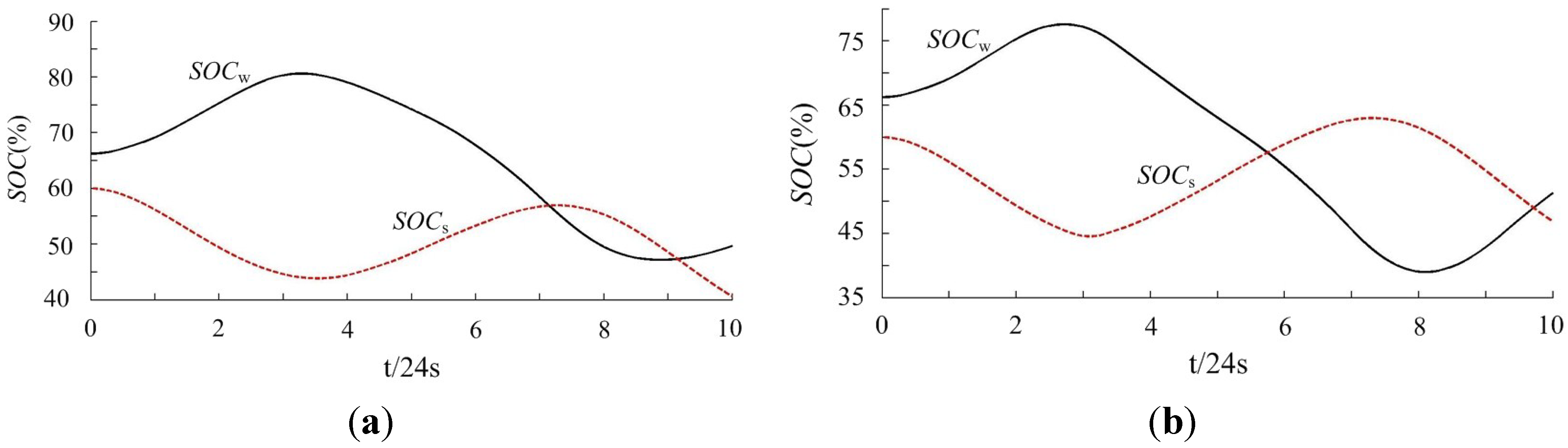
4. Scheduling Strategy of Distributed Energy Sources Based on SOC

Power-sharing among DESs belongs to the category of optimized operation, and the goal is to maximize the use of clean energy in this work. Here, the SOCx is taken as a judgment signal to implement the coordinated allocation and to remove the normal load or the limited source, as shown in Figure 8, because it can accurately reflect the potential ability of output power of wind and solar DES.
Figure 8. Block diagram of the scheduling strategy of the islanded series micro-grids (SMGs).
Energies 07 07878 g008
If a renewable energy shortage appears under extreme weather conditions, the normal load would be removed and the key load should be supplied by a micro gas turbine. If the energy is sufficient, the output power of the micro gas turbine should be reduced. The scheduling strategy is eventually adopted, as shown in Figure 8.
After being started, the system is involved in circulated monitoring. As shown in Figure 8, (1 − x) represents the other random source of x represented and vmmax is the allowed maximum value of the modulation signal in the whole process. SOCxup and SOCxdown are the threshold values of SOCx of one energy storage unit. The charging of ultra-capacitor ESS is limited when SOCx is more than SOCxup. Discharging is limited when SOCx is less than SOCxdown. The SOCx is defined as the following:
S O C x = E x 0 t o t p x ( t ) d t E x N
where ExN is the capacity of ultra-capacitor unit and Ex0 is the initial capacity. It is clearly found that the relation, i.e., vm1 + vm2 + vm3 = 3vm is always maintained throughout the whole process of stand-alone operation, which avoids producing the negative influence.

5. Simulation and Discussions

5.1. Parameters of the System

The effect of the power-sharing method for the series micro-grid is validated in detail via the simulation model based on Matlab/Simulink software. The capacities of the direct drive permanent magnet synchronous wind power generation and of the MGT were 4 and 3 kVA, respectively, in the single phase system. In view of the photovoltaic array, the open circuit voltage Uoc was 108.8 V and the short circuit current Isc was 32.6 A. The voltage Umax was about 97 V at a maximum power Pmax of 3.05 kW.
To make the change-trend of the SOC more obvious for observation in a short span of time, a smaller capacity ultra-capacitor was configured in DC link of wind and solar DES. Their capacities are assumed to be 4 and 3 Ah, respectively. SOC0xmax, SOC0xmin, SOC0xup and SOC0xdown are respectively equal to 0.9, 0.3, 0.75 and 0.45. However, a running time of 4 minutes was reduced to 10 s, using the method from literature [18]. The parameters of the controller and filter are given in Table 1.
Table 1. Controller and filter parameters of the simulated 10 kW 220 V SMG.
ParameterSymbolValueParameterSymbolValue
Filtering inductorLf1 mHResonant frequencyωo100π rad
Filtering capacitorCf80 μFCut-off frequencyωc5 rad
Equivalent resistancere0.3 ΩMaximum modulation indexmmax0.95
Proportional coefficient of current regulatorkip0.02Reference of dc link Voltage U dc * 140 V
Proportional coefficient of QPR controllerkp0.22Nominal rms Voltage phase to grounduc220 V
Integral coefficient of QPR controllerki25Carrier frequencyfc2 kHz

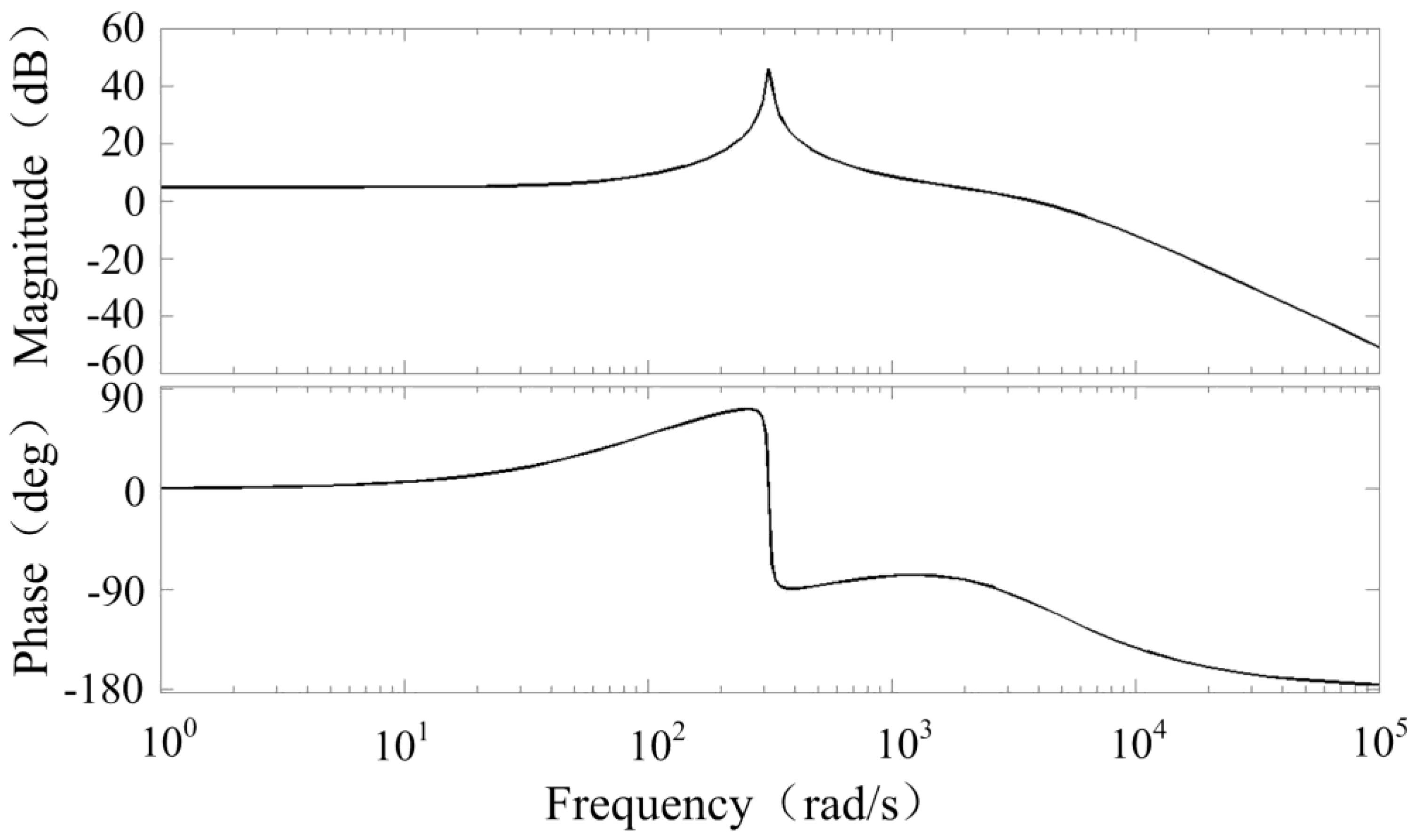
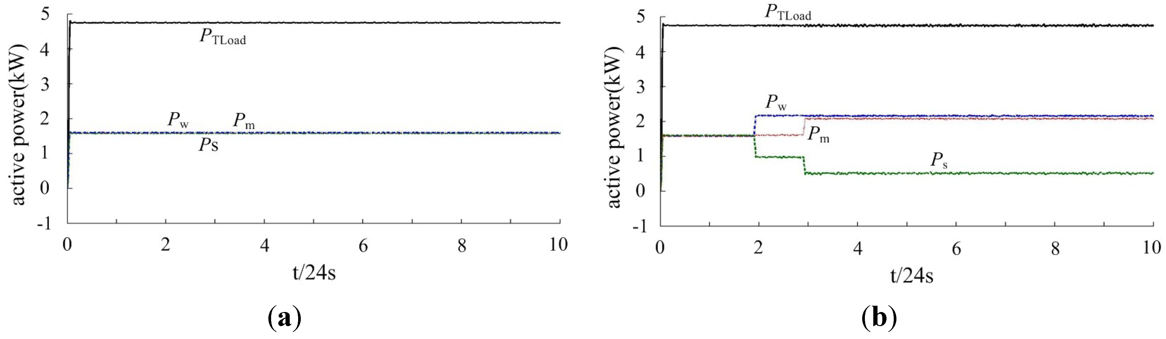
5.2. Single-Phase System

In Figure 9, the curves of SOCw and SOCs of energy storage systems in the single-phase SMG are shown under different power-sharing conditions. It is seen from Figure 9a that SOCwmax in wind DES is 83% and SOCwmin is 48%. SOCsmax is 60%, i.e., the initial value of SOCsmin is 39%, i.e., the terminal value in the solar source.
By comparing the two curves, it can be seen that SOCs is in a trough when the SOCw is at a peak, so that their storage state almost present an opposite trend. The maximum difference of SOC is defined as the following formula:
Δ S O C max ' = max { S O C w ( t ) S O C s ( t ) }
Δ S O C max ' is approximately equal to 38%. They both experience average load power sharing conditions. Figure 9b reflects change trends of SOCw and SOCs under coordinated power-sharing conditions. Here, SOCwmax was 77% and SOCwmin was 40%, and SOCsmax was 63% and SOCsmin was 45%, such that Δ S O C max ' was equal to 31%.
The curves of output active power PW, PS, PM, and load power PTload are shown in Figure 10. Figure 10a reflects the conditions of average allocation. At this point, the output power of each energy source is equal. Meanwhile, the sum of output power of each source is equal to load power.
It is found according to Figure 9b and Figure 10b that the state of SOCw > SOCwup occurs when the run-time is up to about 48 s. The SOCw ranges from SOC0wmin to SOC0wmax, and crosses the threshold at that moment. While the state of SOCs does not radically change, cooperative operation between wind and solar DES starts. The increment of output power of the wind DES is about 0.9 kW, and the power variation is balanced by solar DES.
The state of SOCs < SOCsdown, SOCw > SOCwup appears at 72 s, then the output of solar DES decreases and the decrement of micro energy source is about 0.5 kW. Here, the power variation is compensated by the micro gas turbine, and the wind DES still maintains the precious output. Effectiveness of the power-sharing strategy can be seen in Figure 9 and Figure 10.
Figure 9. SOCw and SOCs of energy storage systems under different sharing strategies of load power. (a) Average allocation of load power; (b) Coordinated allocation of load power.
Energies 07 07878 g009
Figure 10. Output power of wind/solar/micro gas turbine DES. (a) Average allocation of load power; (b) Coordinated allocation of load power.
Energies 07 07878 g010

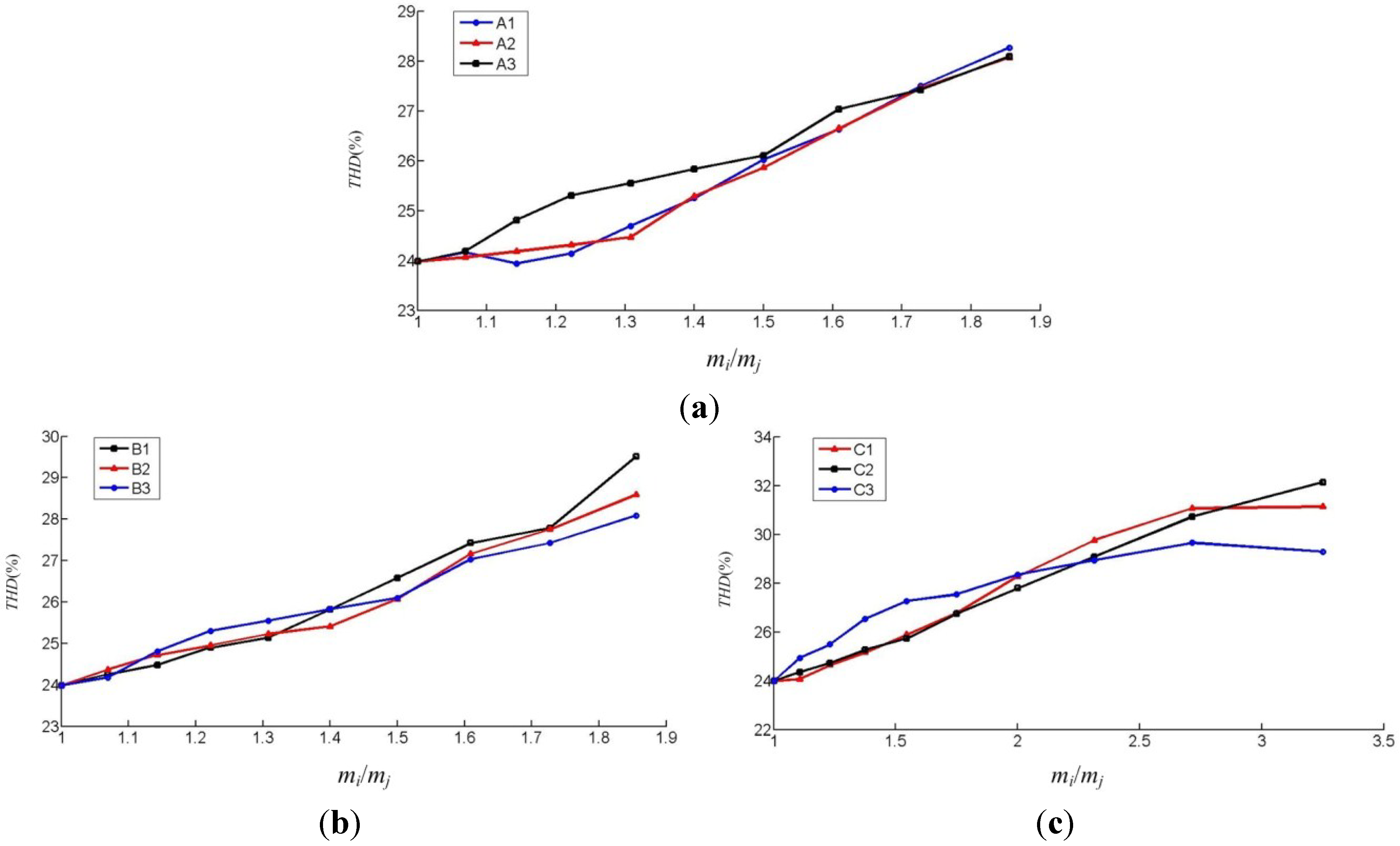
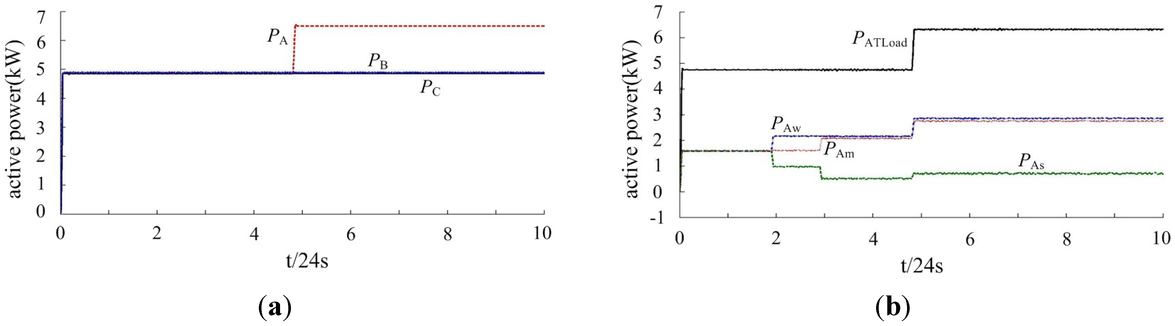
5.3. Three-Phase System

The three-phase series micro-grid is comprised of three symmetrical single-phase systems and the parameters of each subsystem are the same as Section 5.1. This combined system adopts the star configuration and separate phase control. Detailed simulation results are demonstrated, as shown in Figure 11, Figure 12 and Figure 13. Figure 11 shows the output power of each subsystem under the conditions of unbalanced loads. The output power of the each subsystem in the combination system is equal before 117.705 s; the A-phase load changes in step form at 117.705 s. On the other hand, the effectiveness of coordinated sharing in the whole operation process can be illustrated by the Figure 10b.
Figure 12 illustrates curves of the output voltage and current within 10 electric cycles. This fragment contains the moment with the step change of the A-phase load, which illustrates that the output voltage of the system is stable during an islanded operation, even when suffering from load disturbance. That is to say, the control performance is admirable whether it is a single phase or three phase system. Figure 13 illustrates the voltage (phase to neutral) waveform with the seven-level and phase currents of the A-phase subsystem.
Figure 11. Output of the three-phase series micro-grid. (a) Output power of A, B, C phase subsystems; (b) Output power of DES in the A-phase subsystem with an emergency.
Energies 07 07878 g011
Figure 12. Output voltage and current of three phase system within 10 cycles. (a) Phase current; (b) Line voltage.
Energies 07 07878 g012
Figure 13. Voltage and current of A-phase subsystem.
Energies 07 07878 g013

6. Conclusions

The novel method combining master with auxiliary control has good performance for power-sharing among different DESs. The coordinated function is flexibly regulated according to the SOC in real time, which is good for the use of clean energy, decreasing the size of the energy storage system and reducing the chance of cutting-off the confined random source. The master control function can keep the islanded system stable. Meanwhile, the auxiliary control realizes coordinated sharing and does not affect the master function.
It is found in the research process that active power is shared by a certain proportion and output reactive power is changed by the same conditions as well. This feature in the system with AC-type DES can be refined, for instance, the nth harmonic can be injected in the rectifier link. Only with DC-type sources, would the system need further research. Another novel strategy with average share of reactive power and certain proportional sharing of active power may needs to be studied in future.

Acknowledgments

This work was supported by National Natural Science Foundation of China (51467010) and Science and technology support projects in Gansu province (1204GKCA003).

Author Contributions

Wei-Man Yang searched out the active power-sharing method and drafting the article, Xing-Gui Wang provided the funding. Valuable comments on a first draft were received from Xing-Gui Wang, Xiao-Ying Li and Zheng-Ying Liu. All four were involved in revising the paper.

Conflicts of Interest

The authors declare no conflict of interest.

References

  1. Llaria, A.; Curea, O.; Jiménez, J.; Camblong, H. Survey on microgrids: Unplanned islanding and ralated inverter control techniques. Renew. Energy 2011, 8, 2052–2061. [Google Scholar] [CrossRef]
  2. Belvedere, B.; Bianchi, M.; Borghetti, A. A microcontroller-based power management system for standalone microgrids with hybrid power supply. IEEE Trans. Actions Sustain. Energy 2010, 3, 422–431. [Google Scholar] [CrossRef]
  3. Wang, X.-G.; Yang, W.-M. Study on characteristics of a microgrid with micro source inverters connected in series. Power Syst. Prot. Control 2013, 21, 130–135. [Google Scholar]
  4. Yang, W.-M.; Wang, X.-G. Research on influence of micro-source characteristics on voltage stability of the series micro-grid. Power Syst. Technol. 2013, 9, 2446–2451. [Google Scholar]
  5. Shi, X.; Jiang, J.; Guo, X. An efficiency-optimized isolated bidirectional DC-DC converter with extended power range for energy storage systems in microgrid. Energies 2013, 6, 27–44. [Google Scholar] [CrossRef]
  6. Rodolfo, D.-L.; Bernal-Agust, J.L.; Contreras, J. Optimization of control strategies for stand-alone renewable energy systems with hydrogen storage. Renew. Energy 2007, 32, 1102–1126. [Google Scholar] [CrossRef]
  7. Calais, M.; Agelidis, V.G.; Meinhardt, M. Multilevel converters for single-phase grid connected photovoltaic systems: An overview. Solar Energy 1999, 5, 325–335. [Google Scholar] [CrossRef]
  8. Rodríguez, J.; Lai, J.-S.; Peng, F.Z. Multilevel inverters: A survey of topologies, controls, and applications. IEEE Trans. Ind. Electron. 2002, 4, 724–738. [Google Scholar] [CrossRef]
  9. Ertl, H.; Kolar, J.W.; Zach, F.C. A novel multicell DC–AC converter for applications in renewable energy systems. IEEE Trans. Ind. Electron. 2002, 5, 1048–1057. [Google Scholar] [CrossRef]
  10. Villanueva, E.; Correa, P.; Rodríguez, J. Control of a single-phase cascaded H-bridge multilevel inverter for grid-connected photovoltaic systems. IEEE Trans. Ind. Electron. 2009, 11, 4399–4406. [Google Scholar] [CrossRef]
  11. Chen, Y.; Xia, M.; Zhu, Z. Photovoltaic grid-connected cascaded inverter based on stepped waveforms and instantaneous value feedback hybrid control. Autom. Electr. Power Syst. 2012, 14, 172–176. [Google Scholar]
  12. Cecati, C.; Ciancetta, F.; Siano, P. A multilevel inverter for photovoltaic systems with fuzzy logic control. IEEE Trans. Ind. Electron. 2010, 12, 4115–4125. [Google Scholar] [CrossRef]
  13. Cortes, P.; Kouro, S.; Barrios, F. Predictive control of a single-phase cascaded H-bridge photovoltaic energy conversion system. In Proceedings of the 2012 IEEE 7th International Power Electronics and Motion Control Conference—ECCE Asia, Harbin, China, 2–5 June 2012; pp. 1423–1428.
  14. Hamzeh, M.; Ghazanfari, A.; Mokhtari, H. Integrating hybrid power source into an islanded MV microgrid using CHB multilevel inverter under unbalanced and nonlinear load conditions. IEEE Trans. Energy Convers. 2013, 3, 643–651. [Google Scholar] [CrossRef]
  15. Emamian, S.; Hamzeh, M.; Paridari, K. Robust decentralized voltage control of an islanded microgrid under unbalanced and nonlinear load conditions. In Proceedings of the IEEE International Conference on Industrial Technology, Cape Town, South Africa, 25–28 February 2013; pp. 1825–1830.
  16. Shi, J.-J.; Gou, W.; Yuan, H. Research on voltage and power balance control for cascaded modular solid-state transformer. IEEE Trans. Power Electron. 2011, 4, 1154–1166. [Google Scholar] [CrossRef]
  17. Kesraoui, M.; Korichi, N.; Belkadi, A. Maximum power point tracker of wind energy conversion system. Renew. Energy 2011, 36, 2655–2662. [Google Scholar] [CrossRef]
  18. Liu, X.; Jiang, Q. AN optimal coordination control of hybrid wind/photovol-taic/energy storage system. Autom. Electr. Power Syst. 2012, 14, 95–100. [Google Scholar]

