Article

Development and Characterization of an Electrically Rechargeable Zinc-Air Battery Stack

Department of Chemical Engineering, Tsinghua University, Beijing 100084, China
*
Author to whom correspondence should be addressed.
Energies 2014, 7(10), 6549-6557; https://doi.org/10.3390/en7106549
Submission received: 29 July 2014 / Revised: 15 September 2014 / Accepted: 25 September 2014 / Published: 13 October 2014

Abstract

:
An electrically rechargeable zinc-air battery stack consisting of three single cells in series was designed using a novel structured bipolar plate with air-breathing holes. Alpha-MnO2 and LaNiO3 severed as the catalysts for the oxygen reduction reaction (ORR) and oxygen evolution reaction (OER). The anodic and cathodic polarization and individual cell voltages were measured at constant charge-discharge (C-D) current densities indicating a uniform voltage profile for each single cell. One hundred C-D cycles were carried out for the stack. The results showed that, over the initial 10 cycles, the average C-D voltage gap was about 0.94 V and the average energy efficiency reached 89.28% with current density charging at 15 mA·cm−2 and discharging at 25 mA·cm−2. The total increase in charging voltage over the 100 C-D cycles was ~1.56% demonstrating excellent stability performance. The stack performance degradation was analyzed by galvanostatic electrochemical impedance spectroscopy. The charge transfer resistance of ORR increased from 1.57 to 2.21 Ω and that of Zn/Zn2+ reaction increased from 0.21 to 0.34 Ω after 100 C-D cycles. The quantitative analysis guided the potential for the optimization of both positive and negative electrodes to improve the cycle life of the cell stack.

Graphical Abstract

1. Introduction

Zinc air batteries are promising next generation power storage solutions for portable electronic devices, electric vehicles (EVs), and large-scale stationary energy storage systems, etc. [1,2,3]. Their practical specific energy density can be as high as 470 Wh·kg−1, which is about two times higher than that of lithium-ion batteries (about 200 Wh·kg−1) [3,4,5]. Oxygen, as a cathode active material, can be directly taken from ambient air leading to no extra storage system required and no cathode costs. Moreover, using zinc as the anode has various advantages such as low cost, abundant resources, and no toxicity, etc. [6].
Primary zinc air batteries and mechanically rechargeable batteries have been widely investigated recently and primary button cells have been commercialized, such as in hearing-aid devices [7]. However, mechanically rechargeable zinc air batteries suffer from obvious limitations because of the lack of public refueling stations and zinc regeneration facility requirements. This greatly decreases the available energy efficiency and is a hurdle in the production and market growth for commercialization [1].
An electrically rechargeable zinc air battery stack is a unique approach to obtain multiple performance improvements over present batteries from a technical and an economic point of view. Recent advances in bifunctional electrocatalysts for both the oxygen reduction reaction (ORR) and the oxygen evolution reaction (OER) provide strong support for the development of bifunctional air electrodes for zinc air batteries [8,9,10]. To our knowledge, almost all studies of electrochemically rechargeable zinc air batteries have been at the single cell scale, especially for the evaluation of catalysts [10]. In this paper, an electrically rechargeable three-cell zinc-air battery stack was designed and built for the first time using novel structured bipolar plate with air-breathing holes. Anodic and cathodic polarization curves were obtained. One hundred charge-discharge cycles were carried out and a degradation of only 1.56% was found for the charging performance, and the average energy efficiency of the initial 10 cycles reached 89.28%. Moreover, the degradation mechanism of the individual electrode for the degraded performance of discharging potential was analyzed with the galvanostatic electrochemical impedance spectroscopy (EIS) method.

2. Experimental Section

2.1. Design and Assembly of the Three-Cell Zinc Air Battery Stack

An air electrode with a gas diffusion layer (GDL), a catalytic coated layer (CCL) and a current collector (Ni mesh, 60 orders) between them was fabricated in our lab. For the home-made bifunctional catalyst, alpha-MnO2 and LaNiO3 were used for the oxygen reduction reaction (ORR) and the oxygen evolution reaction (OER), respectively [11]. The CCL was fabricated using alpha-MnO2, LaNiO3, a PTFE emulsion (60 wt%), and carbon nanotubes (CNTs) (weight ratio 1:1:3:5). A porous Teflon membrane (thickness 40 µm) served as the GDL. A PTFE membrane was pressed into the other side of the Ni mesh and then the whole air electrode was pressed at 20 MPa. The final thickness was ~0.3 mm and the active surface area was 9 cm2.
Figure 1a shows a schematic diagram of an electrically rechargeable zinc air battery stack and the photo of three-cell stack established with bipolar plates is shown in Figure 1b. Figure 1c shows a novel bipolar plate with an air-breathing hole connecting the negative electrode of cell #1 and the adjacent positive electrode of cell #2. The bipolar plate with the novel structure overcomes the technical difficulty in connecting the air electrode and the adjacent zinc electrode in series. The zinc plate (active area: 25 cm2; thickness: 10 mm) was bonded to the cavity of the bipolar plate (Cu plate and frame, thickness: 10 mm) with silver-epoxy adhesive (Jonby Electronic Co., Ltd., Nanjing, China) and it was directly exposed to an alkaline solution. The alkaline solution used was 0.4 M ZnO dissolved in 6 M KOH. The other side of the bipolar plate with the air rectangular holes (50 mm × 2 mm) was directly connected to the GDL edge-clad by a Ni plate (0.1 mm thick). The CCL with the active area of 25 cm2 was exposed to the same alkaline solution above, which was contained in a plate frame chamber (100 × 100 × 10 mm) made of PVC material.
Figure 1. (a) Schematic diagram of an electrically rechargeable zinc air battery stack; (b) photo of the three-cell zinc air battery stack; (c) photo of the bipolar plate with air-breathing hole connecting the negative electrode of cell #1 and the adjacent positive electrode of cell #2.
Energies 07 06549 g001

2.2. Performance Test of the Three-Cell Zinc Air Battery Stack

Each single cell was numbered in sequence from the negative electrode connected to the endplate to the positive electrode as follows: cell #1, cell #2, and cell #3. The ohmic resistance of each cell was tested by ohmmeter (DME-20 cell testing instrument, Nanjing Daming Co., Ltd., Nanjing, China). The anodic and cathodic polarization curves for each cell were obtained: the three-cell stack discharged or charged for 600 s at different current densities and the steady-state cell voltage value for each battery was recorded after the battery stack system became steady. 100 charge-discharge (C-D) cycles of the electrically rechargeable zinc-air battery stack were carried out. The charging or discharging period was 300 s for each state, and thus this was essentially one accelerated degradation test. Similar test methods using C-D cycles have previously been used for zinc air batteries [3,8,9]. A current density of 15 mA·cm−2 and 25 mA·cm−2 was used for the charging and discharging process, respectively. Electrochemical impedance spectroscopy (EIS) was tested galvanostatically (discharging at 25 mA·cm−2 for each single cell) at an amplitude of 1 mA in the frequency range from 100 kHz to 0.01 Hz before and after 100 C-D cycles using an electrochemical workstation (VersaSTAT 3, Princeton Applied Research, Princeton, NJ, USA).

3. Results and Discussion

3.1. Polarization Performance for Each Cell in the Three-Cell Battery Stack
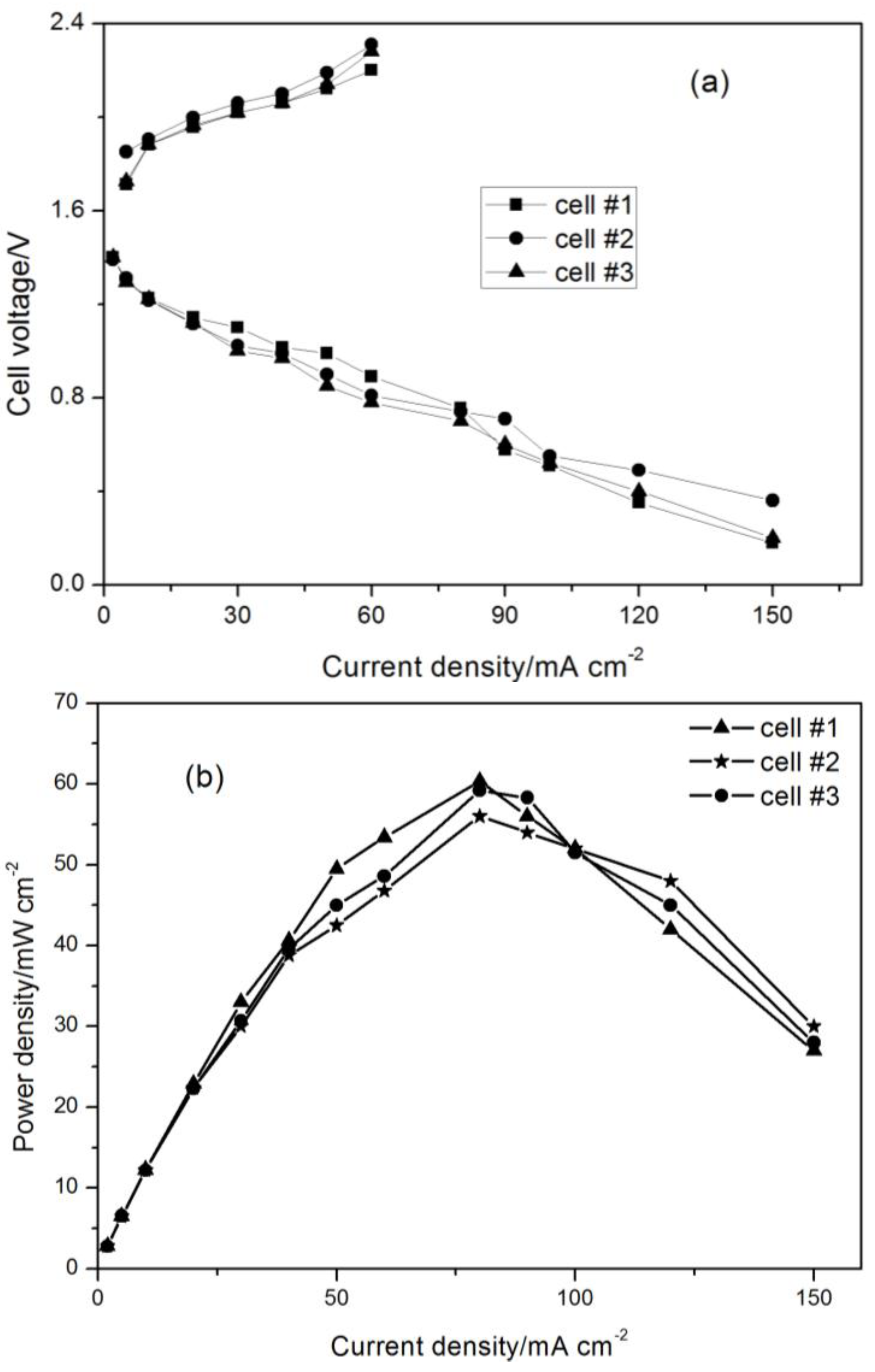
The ohmic resistance of each cell was tested after the assembly of the three-cell battery stack. The ohmic resistance of cell #1, cell #2 and cell #3 was 193.46 mΩ, 201.2 mΩ, and 194.5 mΩ, respectively. The ohmic resistance of positive electrode (cell #1) and the negative electrode (cell #2) connected with bipolar plate was about 2.4 mΩ indicating the excellent and symmetrical structure of the novel bipolar plate. Figure 2a shows the cathodic and anodic polarization curves for each cell. The cell voltage for each battery was recorded after the battery stack system became steady at different test current densities and this was, therefore, the steady-state voltage. The anodic polarization voltage increased by ~0.7 V when the current density increased from 5 to 60 mA·cm−2. The cathodic polarization voltage decreased by ~1.4 V as the current density increased from 5 to 150 mA·cm−2. The average cell resistance including the ohmic resistance, the concentration polarization resistance, and the kinetic polarization resistance was roughly estimated to be about 12.7 Ω·cm2 for the charging process and 9.7 Ω·cm2 for the discharging process, and this indicated a small cell resistance for the zinc air battery system [12]. The power density was calculated in Figure 2b. The peak power density of cell #1 reached 60.4 mW·cm−2 at 80 mA·cm−2. The total peak power of the stack was about 4500 mW. The results of Figure 2 clearly showed that both the anodic and cathodic polarization characteristics of each cell were similar, which indicated a uniform distribution profile of cell voltage under different constant current densities for each single cell in the three-cell battery stack. From another perspective, the even distribution voltage profile of each single cell demonstrated the structure of the stack using the novel bipolar plates with air-breathing holes was excellent and symmetrical.
Figure 2. (a) Anodic and cathodic polarization characteristics for each single cell in the three-cell zinc air battery stack; (b) power density performance for each single cell in the stack.
Energies 07 06549 g002

3.2. Cycling Performance of the Three-Cell Zinc-Air Battery Stack

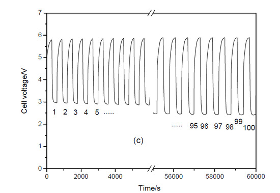
Figure 3 shows 100 charge-discharge cycles for the electrically rechargeable zinc-air battery stack. Enlargements of the initial and 100th cycles are shown in Figure 3a,b, respectively. The steady performance of the charging process was excellent and the charging potential of the three-cell zinc air battery stack only suffered a 1.56% increase after 100 C-D cycles indicating alpha-MnO2 and LaNiO3 exhibited excellent steady performance for the OER activity.
The energy efficiency was calculated using Equation (1) as follows:
Energies 07 06549 i001
In Equation (1), u(t), J and t represent the cell voltage, current density and time, respectively. Based on Equation (1), the average energy efficiency of the initial and the final 10 cycles reached 89.28% and 72.19% (current density: charging at 15 mA·cm−2, discharging at 25 mA·cm−2), respectively. The average charge-discharge cell voltage gap of the initial 10 cycles for the three-cell stack was ~2.82 V and about 0.94 V for each cell, which indicates a small charge-discharge voltage polarization. The high energy efficiency and small C-D voltage gap are mainly due to the high ORR and OER activity of alpha-MnO2 and LaNiO3 electrocatalysts.
Figure 3. Charge-discharge cycles for the electrically rechargeable three-cell zinc-air battery stack: (a) enlargement of the first cycle; (b) enlargement of the 100th cycle; (c) total cycles 100; charging or discharging for 300 s in each state; current density of 15 mA·cm−2 for the charging process; current density of 25 mA·cm−2 for the discharging process.
Energies 07 06549 g003
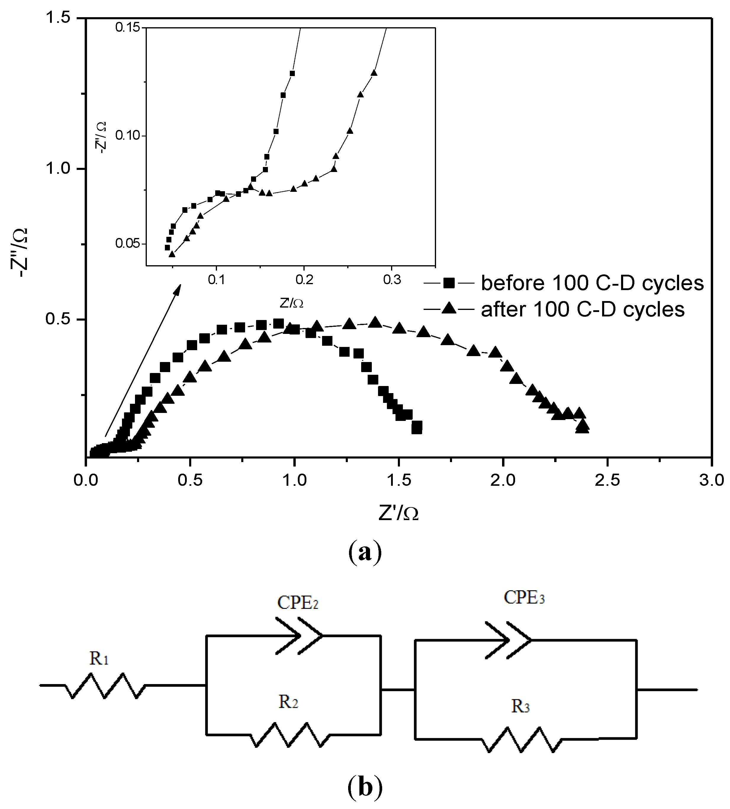
The discharging potential decreased by ~0.43 V and the energy efficiency decreased to 72.19% after 100 C-D cycles. For a further understanding of the degraded discharging performance for the cell, galvanostatic EIS method was carried out for cell #1 before and after 100 cycles in Figure 4a. An equivalent model (see Figure 4b) reported before in metal-air battery was used to analyze the degradation mechanisms of positive and negative electrodes [13]. R1 represents the ohmic resistance of the battery. R2/CPE2 and R3/CPE3 are associated with the negative (Zn − 2e → Zn2+) and positive (O2 + 2H2O + 4e → 4OH) reactions, respectively [13]. EIS results (not shown here) of cell #2 and cell #3 were almost the same with cell #1 for the uniform electrochemical profile of each single cells in the stack. The time constant occurred in the high frequency zone was assigned to R2/CPE2. The charge transfer resistance of negative reaction (Zn − 2e → Zn2+) increased from 0.21 to 0.34 Ω. The zinc plate did not completely regenerate the same structure after the charging process, which caused dendrite growth and degraded the performance of the negative electrode [1]. The time constant occurred at intermediate frequency was associated with R3/CPE3. The charge transfer resistance of the ORR increased from 1.57 to 2.21 Ω. Charging the battery may cause mechanical failure in the air electrode and the decay of ORR activity because of the ORR-OER cycle resulted in some detachment of the ORR catalyst from the supporting materials (CNTs) [9,14]. Besides, G. Toussaint found that MnO2 catalyst used for the ORR dissolved or degraded during the charging process at potentials of more than 0.5 V vs. Hg/HgO/KOH (1 M) [14]. Therefore, the structure or the morphology of the zinc anode (e.g., using Zn foam instead [15]), the ORR catalyst with excellent stability and the cell configuration with other structure (e.g., the tri-electrode structure) require an urgent redesign to improve the C-D cycle life of zinc air battery, which is our on-going research focused on the cell stack.
Figure 4. (a) Nyquist plot of cell #1 at a load current density of 25 mA·cm−2 before and after 100 C-D cycles; (b) the equivalent circuit for the impedance spectra.
Energies 07 06549 g004

4. Conclusions

The novel bipolar plate with air-breathing hole was used for the design of an electrically rechargeable three-cell zinc-air battery stack. The results of anodic and cathodic polarization indicated a uniform distribution cell voltage profile under constant current loads operating conditions in the stack. The charging potential of the battery stack only suffered a 1.56% increase after 100 C-D cycles, an exhibition of excellent stability. The average energy efficiency of the initial and final 10 cycles reached 89.28% and 72.19% (current density: charging at 15 mA·cm−2, discharging at 25 mA·cm−2), respectively. The average charge-discharge cell voltage gap of the initial 10 cycles for the three-cell stack was 2.82 V and the average cell voltage gap was about 0.94 V for each cell, which indicates a small charge-discharge voltage polarization. The degradation mechanism of discharging process for each single electrode analyzed by EIS revealed that the charge transfer resistance of ORR and Zn/Zn2+ reaction increased from 1.57 to 2.21 Ω and 0.21 to 0.34 Ω, respectively.

Glossary

ORR
oxygen reduction reaction
OER
oxygen evolution reaction
C-D
charge-discharge
EVs
electric vehicles
EIS
electrochemical impedance spectroscopy
GDL
gas diffusion layer
CCL
catalytic coated layer
CNTs
carbon nanotubes
R1
the ohmic resistance of the battery
R2
the charge transfer resistance of negative reaction
CPE2
the constant phase element associated with the double electric layer of negative reaction
R3
the charge transfer resistance of positive reaction
CPE3
the constant phase element associated with the double electric layer of positive reaction

Acknowledgments

The authors gratefully acknowledge financial support from the National Natural Science Foundation of China (21276134) and the National 973 Project (No. 2010CB227202).

Author Contributions

Hongyun Ma, Baoguo Wang, Yongsheng Fan and Weichen Hong developed the idea of the three-cell zinc air battery stack. Hongyun Ma, Yongsheng Fan and Weichen Hong established the stack and performed the expreiments. Hongyun Ma and Baoguo Wang analyzed the data and wrote the paper.

Conflicts of Interest

The authors declare no conflict of interest.

References

  1. Li, Y.; Dai, H. Recent advances in zinc-air batteries. Chem. Soc. Rev. 2014, 43, 5257–5275. [Google Scholar] [CrossRef] [PubMed]
  2. Lee, S.M.; Kim, Y.J.; Eom, S.W.; Choi, N.S.; Kim, K.W.; Cho, S.B. Improvement in self-discharge of Zn anode by applying surface modification for Zn-air batteries with high energy density. J. Power Sources 2013, 227, 177–184. [Google Scholar] [CrossRef]
  3. Chen, Z.; Yu, A.; Higgins, D.; Li, H.; Wang, H.; Chen, Z. Highly active and durable core-corona structured bifunctional catalyst for rechargeable metal-air battery application. Nano Lett. 2012, 12, 1946–1952. [Google Scholar] [CrossRef] [PubMed]
  4. Takeguchi, T.; Yamanaka, T.; Takahashi, H.; Watanabe, H.; Kuroki, T.; Nakanishi, H.; Orikasa, Y.; Uchimoto, Y.; Takano, H.; Ohguri, N.; et al. Layered perovskite oxide: A reversible air electrode for oxygen evolution/reduction in rechargeable metal-air batteries. J. Am. Chem. Soc. 2013, 135, 11125–11130. [Google Scholar] [CrossRef] [PubMed]
  5. Lee, J.S.; Kim, S.T.; Cao, R.; Choi, N.S.; Liu, M.; Lee, K.T.; Cho, J. Metal-air batteries with high energy density: Li-air versus Zn-air. Adv. Energy Mater. 2011, 1, 34–50. [Google Scholar] [CrossRef]
  6. Pei, P.; Ma, Z.; Wang, K.; Wang, X.; Song, M.; Xu, H. High performance zinc air fuel cell stack. J. Power Sources 2014, 249, 13–20. [Google Scholar] [CrossRef]
  7. Cheng, F.; Chen, J. Metal-air batteries: From oxygen reduction electrochemistry to cathode catalysts. Chem. Soc. Rev. 2012, 41, 2172–2192. [Google Scholar] [CrossRef] [PubMed]
  8. Du, G.; Liu, X.; Zong, Y.; Hor, T.S.A.; Yu, A.; Liu, Z. Co3O4 nanoparticle-modified MnO2 nanotube bifunctional oxygen cathode catalysts for rechargeable zinc-air batteries. Nanoscale 2013, 5, 4657–4661. [Google Scholar] [CrossRef]
  9. Li, Y.; Gong, M.; Liang, Y.; Feng, J.; Kim, J.E.; Wang, H.; Hong, G.; Zhang, B.; Dai, H. Advanced zinc-air batteries based on high-performance hybrid electrocatalysts. Nat. Commun. 2013, 4. [Google Scholar] [CrossRef]
  10. Chen, Z.; Yu, A.; Ahmed, R.; Wang, H.; Li, H.; Chen, Z. Manganese dioxide nanotube and nitrogen-doped carbon nanotube based composite bifunctional catalyst for rechargeable zinc-air battery. Electrochim. Acta 2012, 69, 295–300. [Google Scholar] [CrossRef]
  11. Ma, H.; Wang, B. A bifunctional electrocatalyst α-MnO2-LaNiO3/carbon nanotubes composite for rechargeable zinc-air batteries. RSC Adv. 2014. [Google Scholar] [CrossRef]
  12. Lee, D.U.; Scott, J.; Park, H.W.; Abureden, S.; Choi, J.Y.; Chen, Z. Morphologically controlled Co3O4 nanodisks as practical bi-functional catalyst for rechargeable zinc-air battery applications. Electrochem. Commun. 2014, 43, 109–112. [Google Scholar] [CrossRef]
  13. Noack, J.; Cremers, C.; Bayer, D.; Tuebke, J.; Pinkwart, K. Development and characterization of a 280 cm2 vanadium/oxygen fuel cell. J. Power Sources 2014, 253, 397–403. [Google Scholar] [CrossRef]
  14. Toussaint, G.; Stevens, P.; Akrour, L.; Rouget, R.; Fourgeot, F. Development of a rechargeable zinc-air battery. ECS Trans. 2010, 28, 25–34. [Google Scholar]
  15. Drillet, J.F.; Adam, M.; Barg, S.; Herter, A.; Koch, D.; Schmidt, V.M.; Wilhelm, M. Development of a novel zinc/air fuel cell with a Zn foam anode, a PVA/KOH membrane and a MnO2/SiOC-based air cathode. ECS Trans. 2010, 28, 13–24. [Google Scholar]