Experimental Study on Frost Height of Round Plate Fin-Tube Heat Exchangers for Mobile Heat Pumps


Abstract
:1. Introduction
2. Experimental Setup
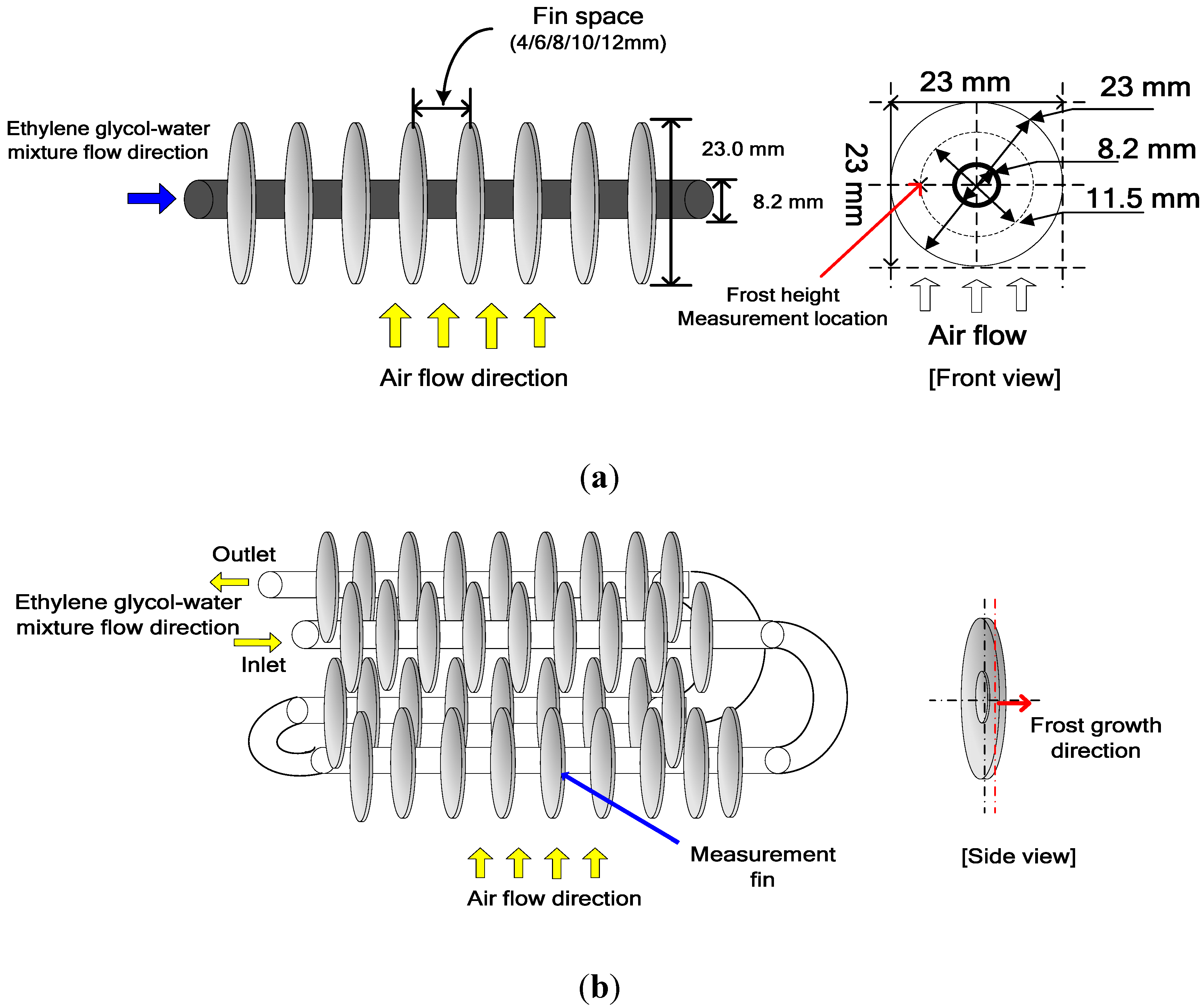
2.1. Test Specifications
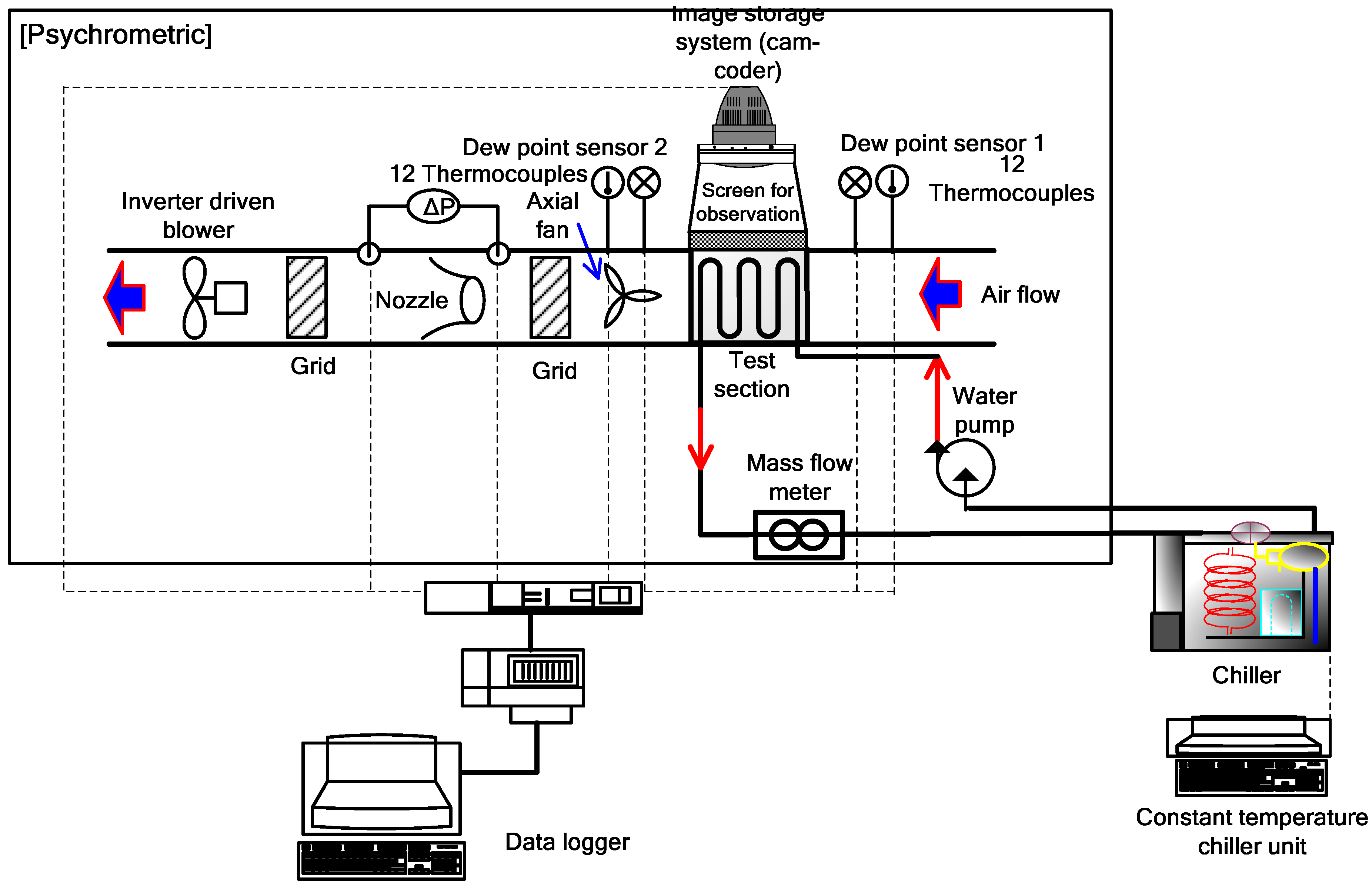
2.2. Frost Height Measurement

| Parameter | Value |
|---|---|
| Fin space (mm) | 4.0/6.0/8.0/10.0/12.0 |
| Fin diameter (mm) | 23.0 |
| Fin thickness (mm) | 0.15 |
| Tube outer diameter (mm) | 8.2 |
| Tube thickness (mm) | 0.5 |
| Tube length (mm) | 650.0 |
| Materials for a fin and a tube | Aluminum |
| Inlet air temperature (°C) | 5.0/8.0/11.0 |
| Inlet air relative humidity (%) | 50/60/70/80 |
| Airflow rate (m3/min) | 0.6/0.8/1.0/1.2 |
| Ethylene glycol-water mixture inlet temperature (°C) | −15.0 |
3. Results
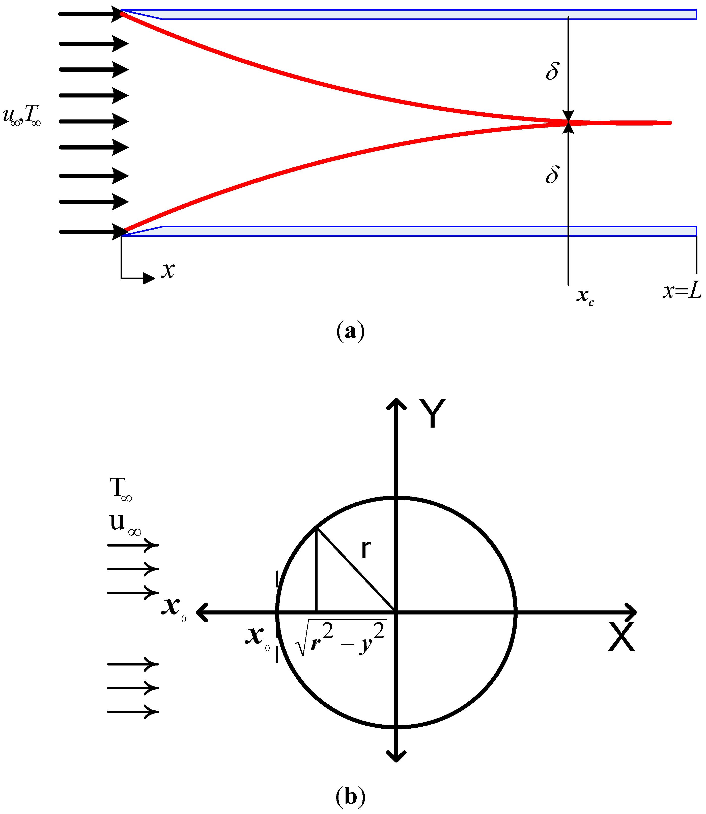
3.1. Boundary Layer
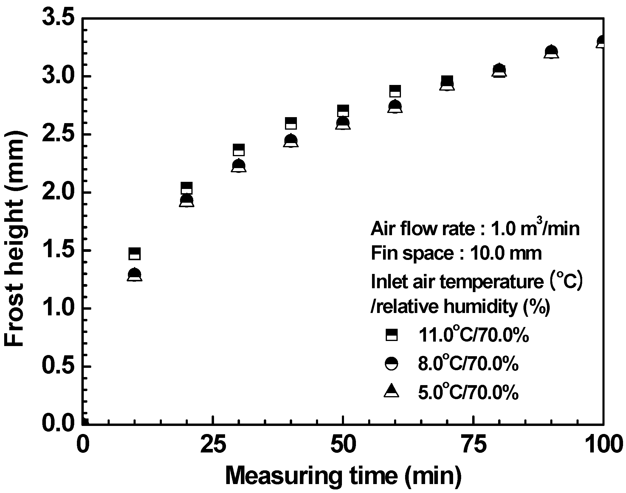
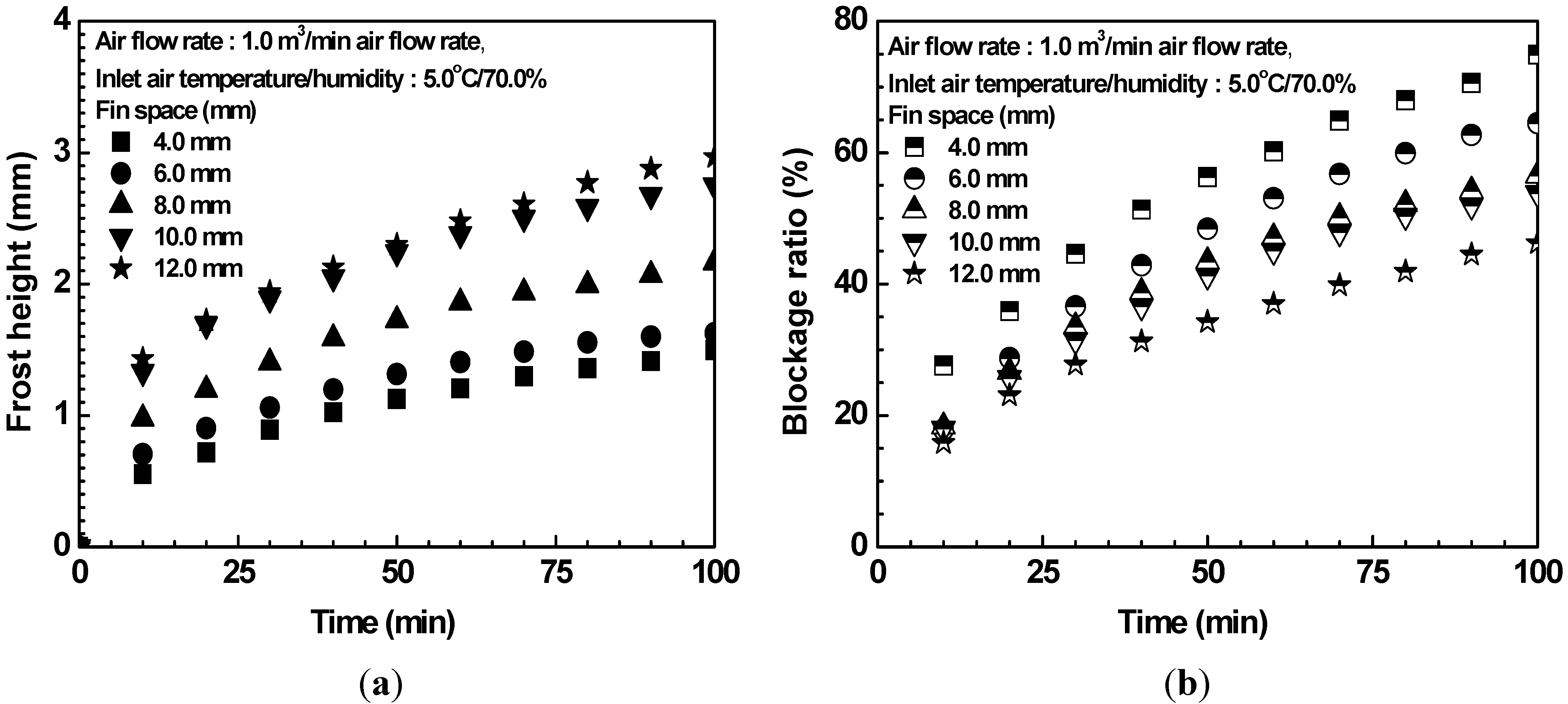
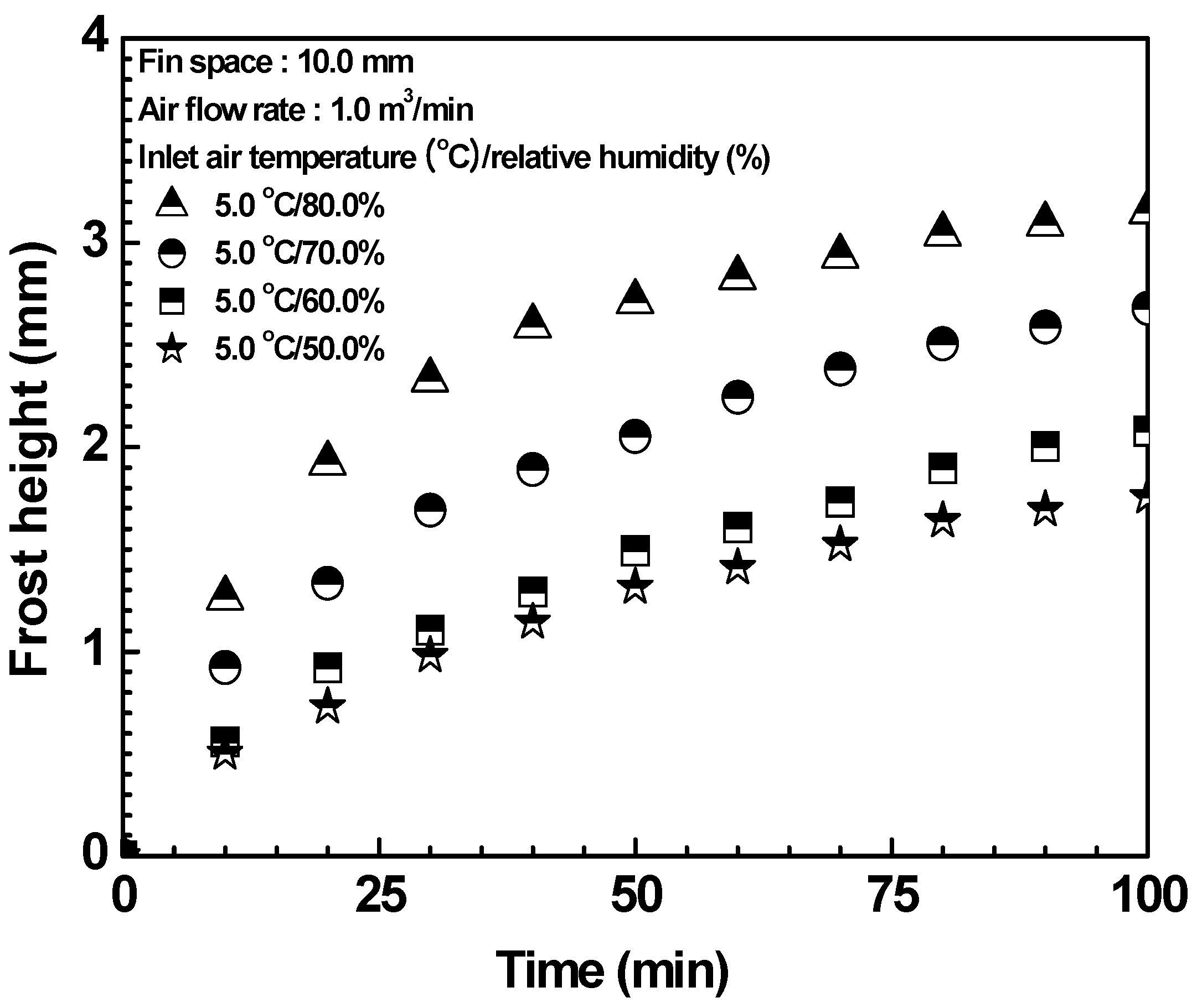
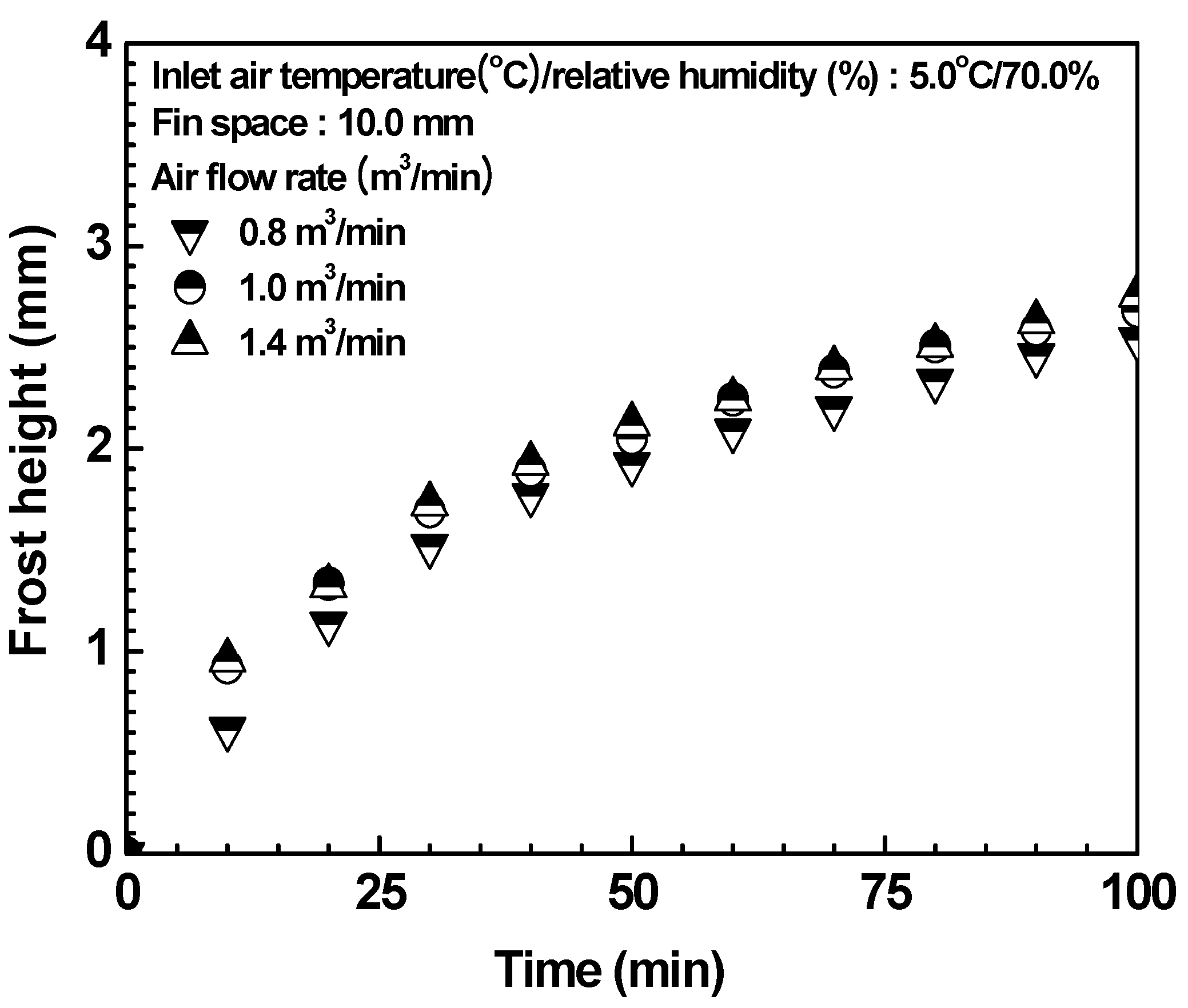
3.2. Frost Growth


4. Summary and Conclusion
Nomenclature
| Ff | Fin space (mm) |
| L | Appropriate characteristic length (mm) |
| T | Temperature (°C) |
| Xs | Frost layer height (mm) |
Greek symbols
| δ | Boundary layer thickness |
| r | Radius (mm) |
| γ | Blockage ratio (%) |
| u | Velocity component in x direction (mm/s) |
| v | Velocity component in y direction (mm/s) |
| x | X-axis |
| y | Y-axis |
Subscripts
| c | current |
| crit | critical |
| s | surface |
| ∞ | free stream |
Acknowledgments
References
- Huang, D.; Li, Q.; Yuan, X. Comparison between hot-gas bypass defrosting and reverse-cycle defrosting methods on an air-to-water heat pump. Appl. Energy 2009, 86, 1697–1703. [Google Scholar] [CrossRef]
- Byrne, P.; Miriel, J.; Lénat, Y. Experimental study of an air-source heat pump for simultaneous heating and cooling, Part 2: dynamic behaviour and two-phase thermosiphon defrosting technique. Appl. Energy 2011, 88, 3072–3078. [Google Scholar] [CrossRef]
- Jones, B.W.; Parker, J.D. Frost formation with varying environmental parameters. J. Heat Transfer 1975, 97, 255–259. [Google Scholar] [CrossRef]
- Brian, P.I.; Reid, R.C.; Shah, Y.T. Frost deposit on cold surfaces. Ind. Eng. Chem. Environ. 1969, 9, 375–380. [Google Scholar]
- Niederer, D.H. Frosting and defrosting effects on coil heat transfer. ASHRAE Trans. 1976, 82, 467–473. [Google Scholar]
- Kondepudi, S.N.; O’Neal, D.L. The effect of frost growth on the performance of louvered finned tube heat exchangers. ASHRAE Trans. 1989, 93, 258–274. [Google Scholar]
- O’Neal, D.L.; Bryant, J.A.; Parker, B. Impact of hydrophobic coating on frost buildup and defrost performance of a heat pump heat exchanger. In Proceedings of the 45th Oji International Seminar, Tomakomai, Japan, September 1997; pp. 181–187.
- Rite, R.W.; Crawford, R.R. The effect of frost growth on the performance of domestic refrigerator-freezer finned tube heat exchanger coils. ASHRAE Trans. 1991, 97, 428–437. [Google Scholar]
- Hayashi, Y.; Aoki, A.; Adachi, S.; Hori, K. Study of frost properties correlating with frost formation types. J. Heat Transfer 1977, 99, 239–245. [Google Scholar] [CrossRef]
- Schneider, H.W. Equation of growth rate of frost formation on the performance of a parallel plate heat exchanger. Int. J. Heat Mass Transfer 1978, 21, 1019–1024. [Google Scholar] [CrossRef]
- Sanders, C.T. The influence of frost formation and defrosting on the performance of air coolers. Ph.D. Thesis, Delft Technical University, Delft, The Netherlands, October 1974. [Google Scholar]
- Sommers, A.D.; Jacobi, A.M. Air-side heat transfer enhancement of a refrigerator evaporator using vortex generation. Int. J. Refrig. 2005, 28, 1006–1017. [Google Scholar] [CrossRef]
- Sommers, A.D.; Jacobi, A.M. Heat transfer enhancement by winglet-type vortex generator array in compact fin-and-tube heat exchangers. Int. J. Refrig. 2008, 31, 87–97. [Google Scholar] [CrossRef]
- Xia, Y.; Zhong, Y.; Hrnjak, P.S.; Jacobi, A.M. Frost, defrost, and refrost and its impact on the air-side thermal-hydraulic performance of louvered-fin, flat-tube heat exchangers. Int. J. Refrig. 2006, 29, 1066–1079. [Google Scholar] [CrossRef]
- Xie, G.; Wang, Q.; Sunden, B. Parametric study and multiple correlations on air-side heat transfer and friction characteristics of fin-and-tube heat exchangers with large number of large-diameter tube rows. Appl. Therm. Eng. 2009, 29, 1–16. [Google Scholar] [CrossRef]
- Shao, L.L.; Yang, L.; Zhang, C.L. Comparison of heat pump performance using fin-and-tube and microchannel heat exchangers under frost conditions. Appl. Energy 2010, 87, 1187–1197. [Google Scholar] [CrossRef]
- Hong, T.; Moallem, E.; Cremaschi, L.; Fisher, D.E. Measurements of frost growth on louvered folded fins of micro-channel heat exchangers Part 1: Experimental methodology. ASHRAE Trans. 2012, 118, 1–7. [Google Scholar]
- Moallem, E.; Cremaschi, L.; Fisher, D.E.; Padhmanabhan, S. Experimental measurements of the surface coating and water retention effects on frosting performance of micro-channel heat exchangers for heat pump systems. Exp. Therm. Fluid Sci. J. 2012, 39, 176–186. [Google Scholar] [CrossRef]
- Cho, C.W.; Lee, H.S.; Won, J.P.; Lee, M.Y. Measurement and evaluation of heating performance of heat pump systems using wasted heat from electric devices for an electric bus. Energies 2012, 5, 658–669. [Google Scholar] [CrossRef]
- Lee, M.Y.; Kang, T.H.; Joo, Y.J.; Kim, Y.C. Heat transfer characteristics of spirally-coiled circular fin-tube heat exchanger under frosting conditions. Int. J. Refrig. 2011, 34, 328–336. [Google Scholar] [CrossRef]
- Incropera, F.P.; Dewitt, D.P. Fundamentals of Heat and Mass Transfer, 4th ed.; John Wiley & Sons: Hoboken, NJ, USA, 2002. [Google Scholar]
- Lee, M.Y. Heat and mass transfer characteristics of a spirally-coiled circular fin tube heat exchanger. Ph.D. Thesis, Korea University, Seoul, Korea, February 2010. [Google Scholar]
- Kim, Y.H.; Kim, Y. Heat transfer characteristics of flat plate finned-tube heat exchangers with large fin pitch. Int. J. Refrig. 2005, 28, 851–858. [Google Scholar] [CrossRef]
- Mon, M.S. Numerical investigation of air-side heat transfer and pressure drop in circular finned-tube heat exchangers. Ph.D. Thesis, Technische Universität Bergakademie Freiberg, Freiberg, Germany, February 2003. [Google Scholar]
- Lee, K.S.; Lee, T.H.; Kim, W.S. An experimental study on the effects of design factors for the performance of fin-tube heat exchanger under cold weather conditions. Trans. KSME 1995, 19, 2657–2666. [Google Scholar]
- Sahin, A.Z. An experimental study on the initiation and growth of frost formation on a horizontal plate. Exp. Heat Transfer 1994, 7, 101–119. [Google Scholar] [CrossRef]
- Lee, S.H.; L, M.Y.; Won, Y.J.; Kim, Y. Frost growth characteristics of spirally-coiled circular fin-tube heat exchangers. Int. J. Refrig. 2012. submitted. [Google Scholar]
© 2012 by the authors; licensee MDPI, Basel, Switzerland. This article is an open access article distributed under the terms and conditions of the Creative Commons Attribution license (http://creativecommons.org/licenses/by/3.0/).
Share and Cite
Lee, M.-Y.; Kim, Y.; Lee, D.-Y. Experimental Study on Frost Height of Round Plate Fin-Tube Heat Exchangers for Mobile Heat Pumps. Energies 2012, 5, 3479-3491. https://doi.org/10.3390/en5093479
Lee M-Y, Kim Y, Lee D-Y. Experimental Study on Frost Height of Round Plate Fin-Tube Heat Exchangers for Mobile Heat Pumps. Energies. 2012; 5(9):3479-3491. https://doi.org/10.3390/en5093479
Chicago/Turabian StyleLee, Moo-Yeon, Yongchan Kim, and Dong-Yeon Lee. 2012. "Experimental Study on Frost Height of Round Plate Fin-Tube Heat Exchangers for Mobile Heat Pumps" Energies 5, no. 9: 3479-3491. https://doi.org/10.3390/en5093479
APA StyleLee, M.-Y., Kim, Y., & Lee, D.-Y. (2012). Experimental Study on Frost Height of Round Plate Fin-Tube Heat Exchangers for Mobile Heat Pumps. Energies, 5(9), 3479-3491. https://doi.org/10.3390/en5093479