1. Introduction
The efficient operation of wind parks calls for a long life time of each wind turbine. As many defects of a turbine can be related to vibrations of the system, the investigation of vibrations caused by rotor imbalances gets more and more attention. The growing size of new wind turbines leads to a more flexible structure and therefore even bigger vibrational amplitudes. Additionally, the operation of large off-shore wind parks requires a careful remote monitoring of imbalances. A well balanced rotor will prevent early fatigue and ensure a safe and economic operation of the wind turbine. Imbalances affect the drive train components as well as the structural health of the turbine [
1]. Hence the detection and elimination of imbalances are of vital importance.
There are two main imbalance causes: the so-called mass imbalance arising from inhomogeneous mass distributions caused by, e.g., manufacturing inaccuracies or water inclusions in the blades’ texture, and aerodynamic imbalances, arising, e.g., from errors in the pitch angles or profile changes of the blades. In wind turbines with no Condition Monitoring System (CMS), imbalances are only detected if the vibrations of the turbine are clearly visible, which is only the case if the turbine rotates with a frequency close to the bending eigenfrequency of the turbine, or if there are already damages in the drive train components. If the turbine is equipped with a standard CMS, an increased presence of the rotating frequency and its multiples in the Fourier spectrum can indicate rotor imbalances. In both cases an expert team has to be employed to detect the imbalance location and quantity. In a time consuming process, the team first tries to detect aerodynamic imbalances by using mainly optical methods. If the aerodynamic imbalances have been removed, the remaining vibrations are measured. With a known test mass placed on one blade, a second set of measurements is obtained, and from both measurements together the mass imbalances can be calculated. This process requires not only a lot of time but also expensive manpower. Therefore, it is advantageous to use automatic detection methods. Presently, such methods to detect mass and aerodynamic imbalances by using signal processing methods as well as trend analysis to generate an alarm system require a learning phase performed under faultless condition of the rotor [
2]. However, they do not allow to compute the actual value and position of the imbalance. To this aim, vibration measurements with and without test weights as described above are still necessary. To replace this expensive procedure by a new CMS feature is the main goal of the authors work.
First results in that direction were achieved for the observation and reconstruction of mass imbalances only [
3]. The mass imbalance reconstruction from noisy vibration measurements was treated as an inverse problem with methods from the regularization theory [
4]. To solve an inverse problem, first we have to handle the direct problem of computing the turbine vibrations for a given imbalance. This can be done by using a mathematical model of the turbine that solves the vibration equation with the Finite Element Method (FEM). Although there already exist several models for wind turbines, in [
3] we developed a new and comparably simple model for two reasons: Firstly, in order to find a solution for the inverse problem the direct problem has to be solved several times. Thus the computations should be very fast. Secondly, the imbalance identification algorithm should be applicable to a large variety of wind turbine types, which means the model should be adaptable without much effort. In short, in our approach the information from the test run with reference imbalances is replaced by the model information, the additional measurements are superficial due to the mathematical model. However, the model proposed in [
3] was restricted to mass imbalances and did not consider aerodynamic imbalances. Moreover, we dealt with a one dimensional model only,
i.e., we considered lateral vibrations. Beside axial and torsional vibrations, aerodynamic imbalances also cause vibrations in lateral direction. Thus, neglecting aerodynamic imbalances leads to wrong reconstructions. The resulting error depends on the location of the aerodynamic imbalance and on the rotational frequency, as loads from aerodynamic imbalances depend on the frequency. If the aerodynamic imbalance is located close to the mass imbalance the forces in lateral direction add and we will end up with a reconstructed mass imbalance that is too big. On the other hand, if the aerodynamic imbalance is located opposite to the mass imbalance, we will get a mass imbalance reconstruction that is too small.
In the present paper we consider a model that allows for a reconstruction of both mass imbalances and aerodynamic imbalance caused by deviations in pitch angles at the same time. Since aerodynamic imbalances also cause vibrations in axial directions and torsional vibration around the tower axis, we had to expand our turbine model in these dimensions. To describe the forces and moments from aerodynamic imbalances we have used the blade element momentum (BEM) method. Due to the BEM method, the direct problem of relating the imbalance cause (here the pitch angle deviation and a mass imbalance) to the vibrations of the turbine becomes non-linear. Nevertheless, the regularization techniques for solving the inverse problem also apply to non-linear problems. To ensure a good imbalance reconstruction we observed that the initial value should already be a fairly good guess for the mass imbalance, which we obtained by our old method described above, assuming the absence of aerodynamic imbalances. We reconstructed a good guess for the mass imbalance from the lateral vibrations neglecting the influence from the pitch error. The result is surely not the correct mass imbalance but serves very well as an initial value for the reconstruction of both imbalance causes.
The paper is organized as follows: In
Section 2, we will present the system of equations connecting vibrations and imbalances. The mass and stiffness matrices are calculated by a model of the turbine that considers vibration in lateral and axial direction as well as torsional vibrations around the tower axis. The description of forces and moments from mass imbalances is relatively easy, the aerodynamic forces and moments are derived with the BEM method. In
Section 3, the vibration equation is solved explicitly, whereas in
Section 4, the inverse problem of deriving the imbalances from the vibrations is considered. It results in a nonlinear optimization problem.
Section 5 contains examples for the numerical calculation of mass and aerodynamic imbalances from artificial vibration data at the top of the tower.
2. System Equation
Before we can think about reconstructing imbalances from vibration measurements we have to be able to handle the other direction,
i.e., for a given imbalance cause we should compute the resulting vibrations of the wind turbine tower. In order to derive appropriate formulas we have to make simplifying assumptions. First we assume that the wind turbine is a flexible shaft (the tower) with an additional mass (the nacelle and the rotor) at the top point, where one part of that mass (the rotor) rotates with a rotational frequency Ω. The movement of such a shaft is described by a Partial Differential Equation (PDE) in time and space. An explicit solution of that equation is seldom possible. Using the Finite Element Method (FEM), the problem can be discretized in space, which results in an Ordinary Differential Equation (ODE) in time. The solution of the ODE is much easier and is a good approximation to the solution of the PDE. The final ODE has the form
where
denotes the mass or inertia matrix,
the stiffness matrix,
the vector of the degrees of freedom and
the load vector.
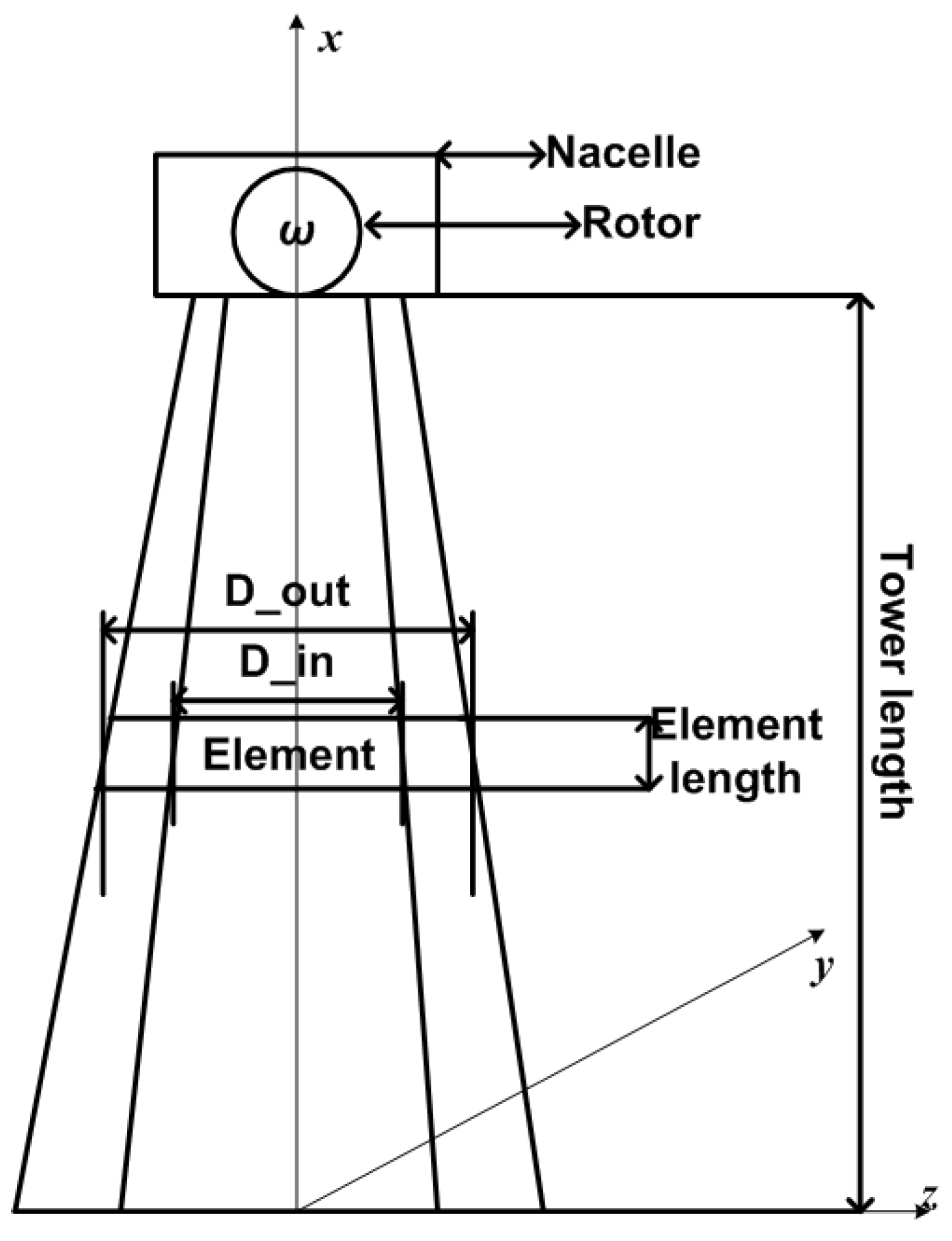
For the FEM approach, we divide the tower into elements that are in our case hollow cylinders. We consider movements in lateral or
z-direction, in axial or
y-direction and torsional movements around the
x-axis, see
Figure 1 for the coordinate system. There are no movements in
x-direction as the tower is supposed to be rigid against shear forces.
Figure 1.
Model of wind turbine.
Figure 1.
Model of wind turbine.
2.1. Establishment of the Mass and Stiffness Matrix
The mass matrix
and the stiffness matrix
are derived based on the Ritz method following exactly the way described in [
5]. We have divided the tower into
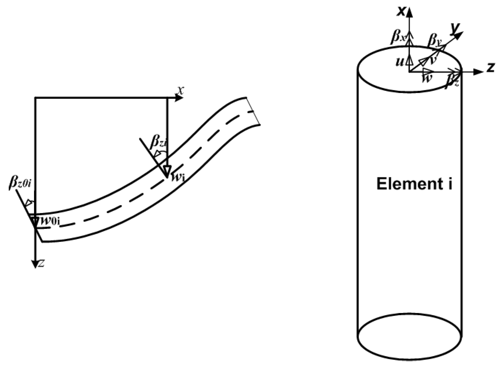
N elements with one node at the bottom and one at the top of each element. Each node has five degrees of freedom (DOF),
- displacement in y- and z-direction,
- cross section rotation (or torsion angle), and
- cross section slope in y- and z-direction,
c.f. Figure 2. We have to take into account the boundary and transition conditions between the elements. The global system displacement vector or vector of DOF is defined by
where the index number denotes the node number. We assume that the base of the tower does not move. Therefore all DOF of the first node are zero and we have
entries. The system stiffness matrix and mass matrix are build from the element stiffness and element mass matrices according to the order in the global displacement vector and have the dimension
. The mass characteristics from rotor and nacelle have to be added in the mass matrix at the corresponding DOF.
Figure 2.
Displacement of a beam.
Figure 2.
Displacement of a beam.
2.2. Establishment of the Load Vector
To complete the description of the system Equation (1), it remains to describe the load vector
. Within the scope of this paper, we assume the wind turbine is only affected at the top node of our FE model, and neglect all loads created, e.g., by wind, in other nodes. The forces and moments in the load vector are ordered according to the order of the DOF in the displacement vector
. Hence, the load vector has the form
where
and
denote forces in
y- and
z-direction,
, and
are moments of forces or torques w.r.t. the
x-,
y- and
z-axis, respectively. Here
because we assume mechanical energy related to
is transformed into electrical energy.
In the following, we want to consider loads that result from
inhomogeneous mass distribution of the rotor, and
aerodynamic forces arising from incorrect pitch angles settings of the rotor blades.
Mass Imbalance
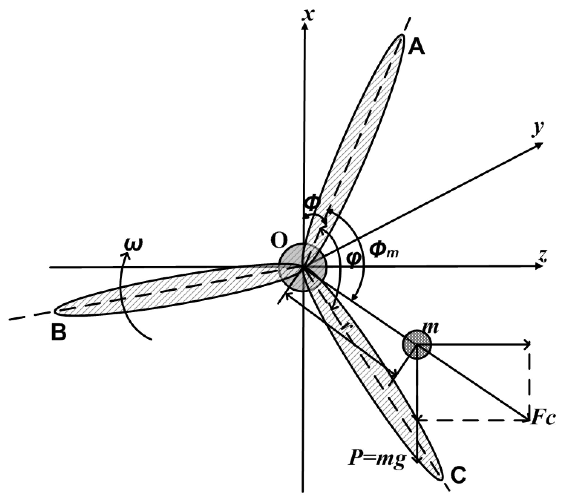
The inhomogeneity of the rotor mass distribution is modeled as point mass
m located in the rotor plane at a distance
r under an angle
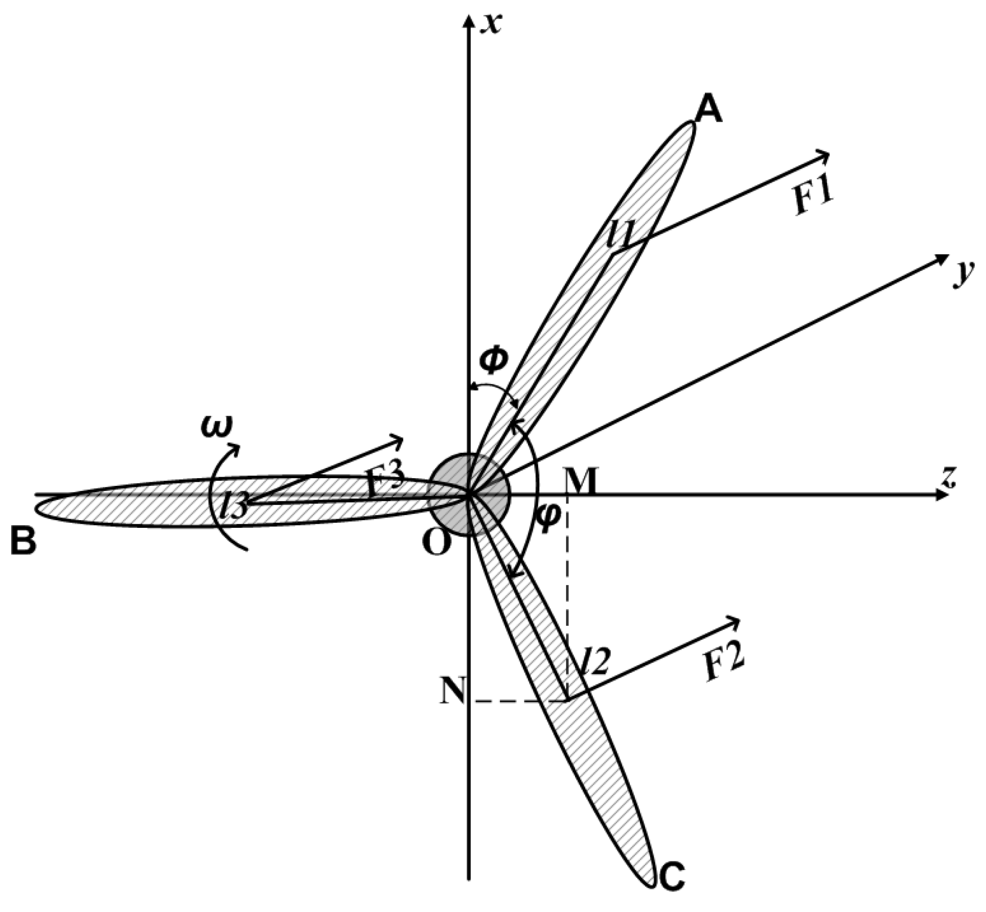
w.r.t. the zero mark at blade A, see
Figure 3. The forces caused by this mass are gravity and centrifugal force. With the angular frequency
, the absolute value for the centrifugal force is given by
Its projections onto the
z- and
x-axis are
Figure 3.
Mass imbalance model.
Figure 3.
Mass imbalance model.
Here,
t is time variable, and
φ is the angle between blade A and the
x-axis. Because the rotational plane has a distance
L to the tower, the forces
and
also produce moments around the
x- and the
z-axes with respect to the tower
Besides, the gravity force of the point mass also creates a small moment around the z-axis. However, this moment is neglected.
Aerodynamic Imbalance
To describe the aerodynamic loads on a wind turbine, we have employed the well known Blade Element Momentum (BEM) theory,
c.f. [
7,
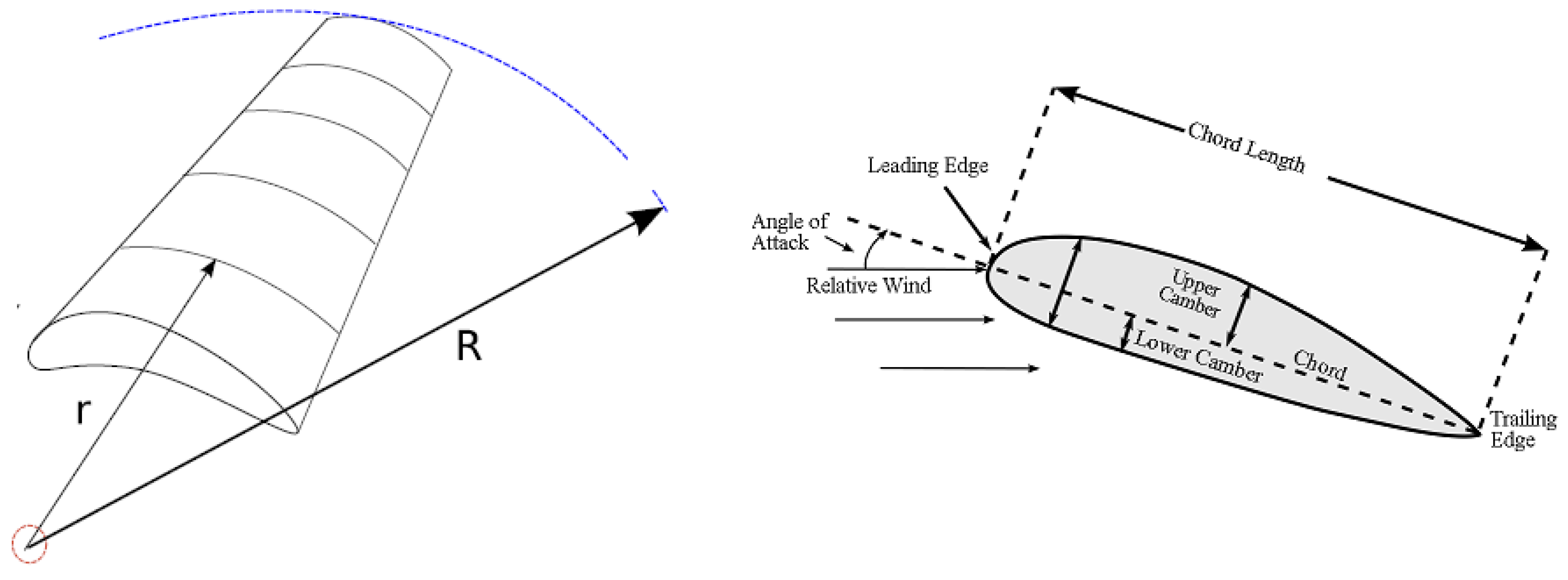
10]. In the BEM theory, we divide the blades into a finite number of elements which are sections of the blades into annulus segments with the center at the root of the blades. The cross section of each element is called “airfoil”, see
Figure 4.
Figure 4.
Blade element model with airfoil.
Figure 4.
Blade element model with airfoil.
Figure 5.
Thrust force on Wind Turbine.
Figure 5.
Thrust force on Wind Turbine.
Figure 6.
Tangential force on Wind Turbine.
Figure 6.
Tangential force on Wind Turbine.
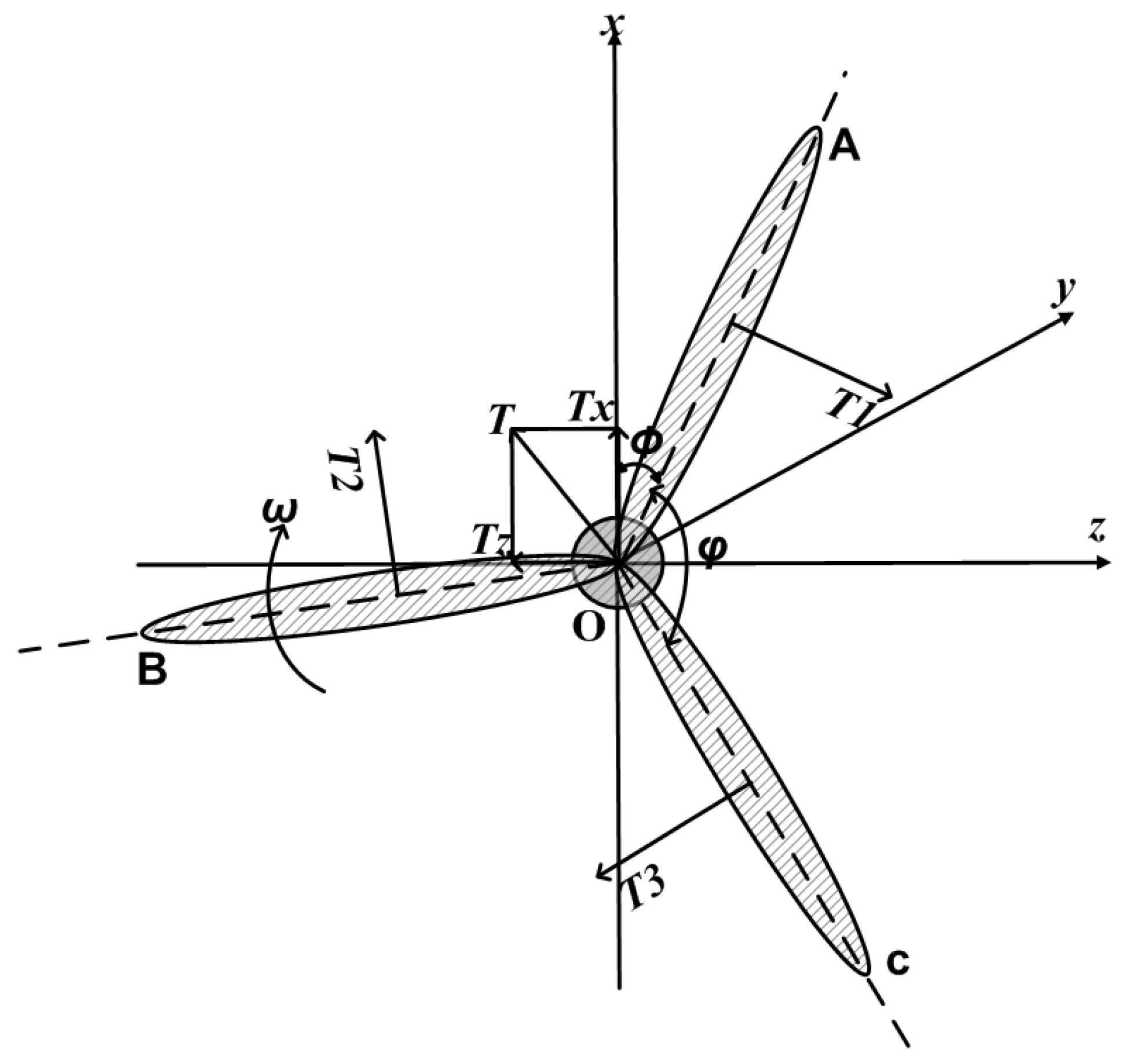
If we are given the airfoil data, the angle of attack of the wind, and the relative wind velocity, as well as a lift and drag coefficient table, we can calculate the normal or thrust forces
F and the tangential forces
T according to the BEM method, see, e.g., [
10], and
Figure 5 and
Figure 6.
The local pitch angle
θ for each blade element,
i.e., the angle between chord and the plane of rotation, is the sum of the adjusted pitch angle
at the blades root and the twist of the blade
β:
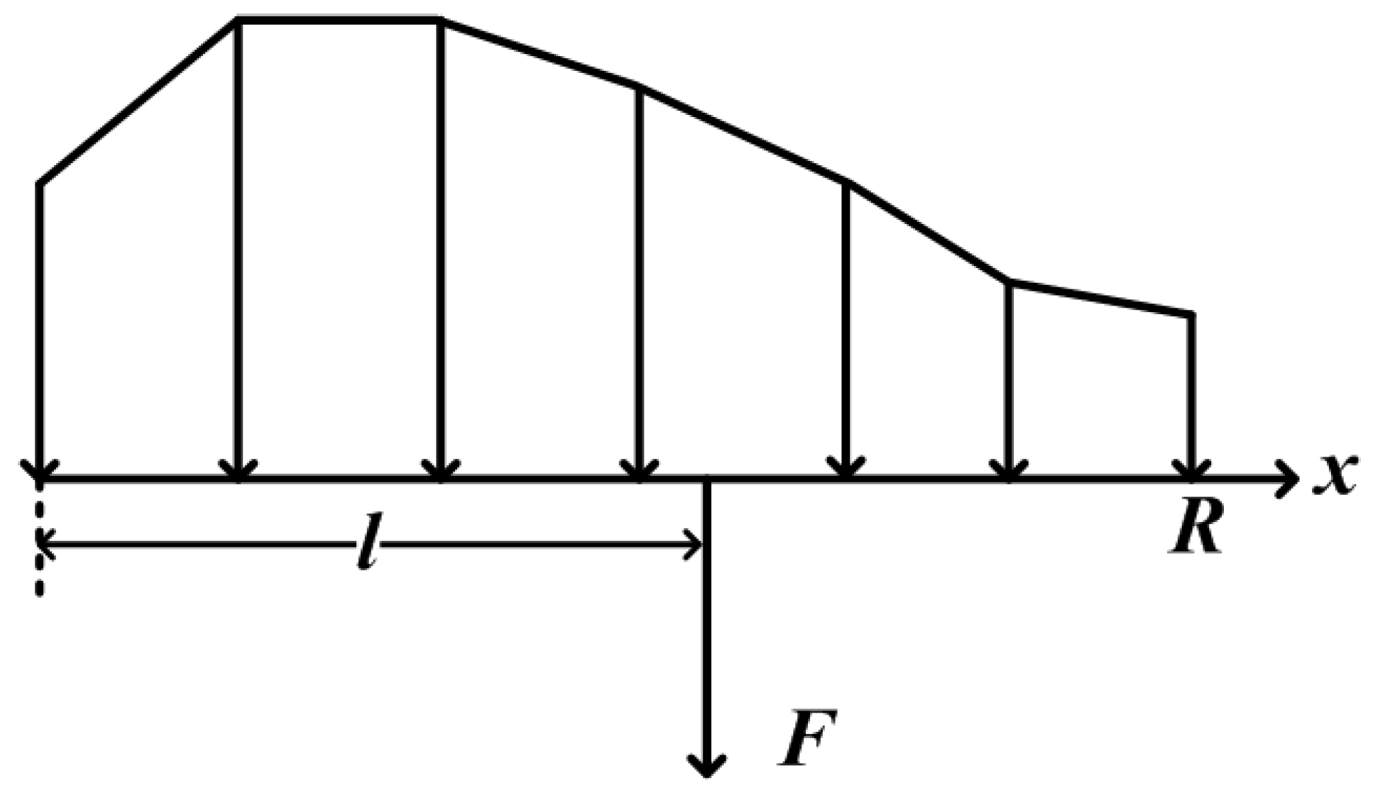
The result of this procedure are forces on each of the blades distributed over all blade elements. However, for manipulation it is more convenient to change the distributed forces on a blade into one equivalent force, see
Figure 7.
The distributed forces and the corresponding lengths are calculated by
Figure 7.
Force equivalent to distributed force.
Figure 7.
Force equivalent to distributed force.
Then, the aerodynamic forces can be modeled as three different thrust forces (normal to the rotor plane) and three different tangential forces as shown in
Figure 5 and
Figure 6. Observing
Figure 5 we see that torques caused by
and
are given by
where we denote by
and
the torques around the
x- and the
z-axis on the rotor of the wind turbine and by
the angle between the rotor blades. Note that if all blades have the same pitch angle, we have
and
. This means that the torques
and
vanish. In addition, it is easy to see that the sum of
and
is the force applying to the rotor in
y direction
Observing the
Figure 5, we know the total force
T is
Projecting
T onto
z axis and
x axis yields
As mentioned before, we have a small distance
L between rotor plane and tower, thus
and
also produces moments around the
x- and the
z-axes:
Load Vector
With the Formulas (3)–(8) the forces and moments from aerodynamic and mass imbalances in (2),
summarize to:
3. Direct Problem
So far we have derived the matrices
,
, and the load vector
. The load
is a function of the absolute value
of the mass imbalances, its phase angle
, and the pitch angles
and
. These five variables determine the forces and moments of forces in (9). The solution of (1) is the sum of the general solution of the homogeneous equation and a particular solution of the inhomogeneous equation with right hand side
. Since
can be written as a sum of a vector
that contains constant entries only, and vectors
and
that contain the amplitudes of the cos- and sin- terms, respectively, we can solve the inhomogeneous equation analytically. Using standard methods,
c.f. [
11], we get
where
Therefore, given a mass imbalance
and a set of pitch angles
the corresponding vibrations
are calculated by first determining
, and applying Formulas (10) and (11) afterwards. The forward problem can be solved for every node in our FE-model. However, in view of the inverse problem, where we rely on measured vibration data, we have to consider that vibration sensors are only mounted at a few positions. In practice there will be an acceleration sensor in
y-direction, one in
z-direction in the middle of the tower top, and, in the best case, one in
z-direction at the end of the tower top. From the difference of the last two the torsional movement around the
x-axis can be derived. Thus only data for the DOF
will be available. Therefore it is necessary to restrict our solution to these positions or DOF. We denote the restricted vibration by
. The final forward operator
A that relates the imbalances causes to the vibrations is the mapping
which performs the calculation of
summarized in Equation (
9), the solution calculation Equation (
10) and the restriction step. Unfortunately, this operator is nonlinear due to the BEM method. This property will determine the possible solution methods for the inverse problem of reconstructing
from measurements of
.
