A Wind Farm Electrical Systems Evaluation with EeFarm-II


Abstract
:1. Introduction
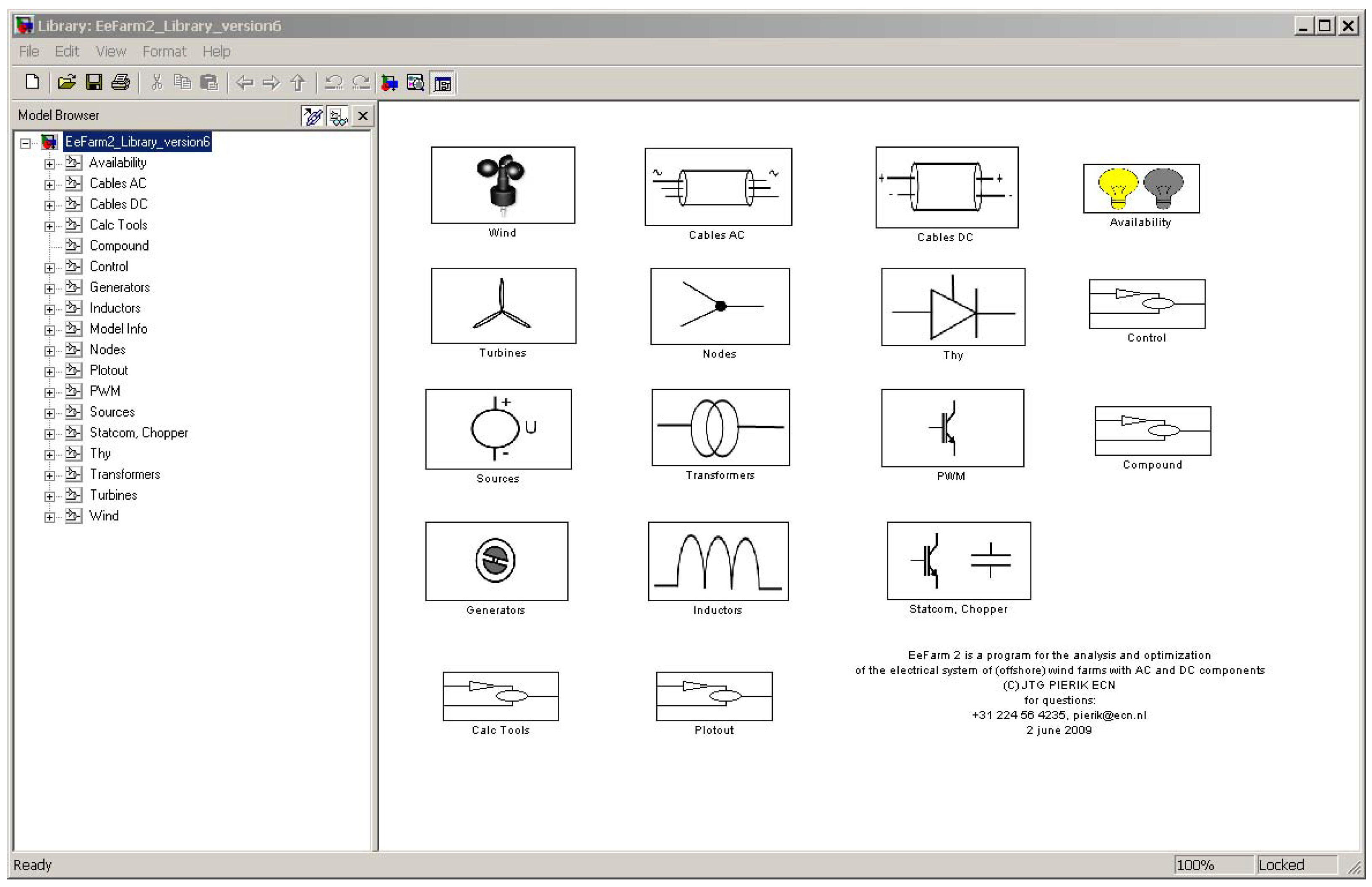
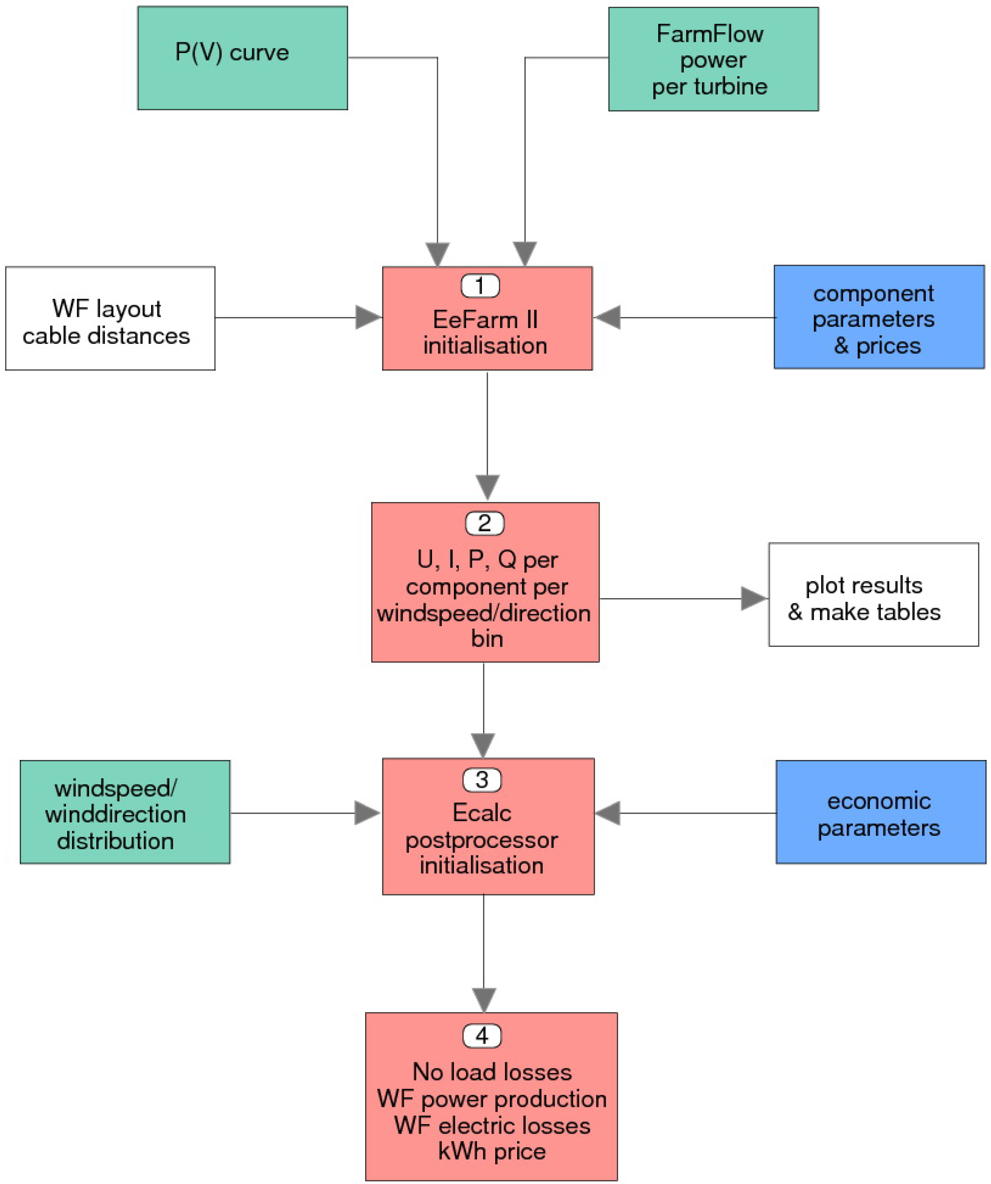
2. EeFarm-II Model and Database Description
- the graphical user interface and library facility, which makes setting up a new wind farm model from an existing set of component models very easy and transparent;
- the Simulink bus signal, which results in simple and error free connection of component models in the wind farm model;
- the Matlab data structure, which simplifies the transfer of component parameters to the wind farm model: complete sets of parameters are assigned by a single command.


| line voltage phasor (RMS) at component output, complex number | (V) | |
| current phasor (RMS) at component output, complex number | (A) | |
| power at component output | (W) | |
| reactive power at component output | (VA) | |
| component losses | (W) | |
| reactive power produced by component | (VA) | |
| sum of component losses | (W) | |
| f | frequency | (Hz) |
| sum of component investment costs | (kEuro) | |
| power not produced due to component failure | (W) | |
| sum of power not produced due to component failure | (W) |
| Model | Simulink block | Remarks |
|---|---|---|
| Wind | Wind | wind input block |
| GCL wake model | Simulink implementation of GCL wind farm wake model | |
| Turbine | Turbine internal curve | single P(V) curve or FyndFarm or FluxFarm input |
| Turbine WF eff. | VSP, CSP or CSS turbine, lookup table GCL preprocessor | |
| VSP turb | single P(V) curve or FyndFarm or FluxFarm input | |
| Generator | Generator Generic | type independent simple generator model |
| IM stat | directly connected induction machine | |
| DFIG | doubly fed induction machine | |
| FCIM | induction machine with full converter | |
| FCSM | synchronous machine with full converter | |
| Transformer | TrafoQ | AC transformer with reactive power calculation |
| Trafo Noloss Nofail | AC transformer, only the transformer ratio | |
| Cable | CableAC | constant temperature π cable model |
| CableDC | constant temperature, earth return DC cable | |
| CableDCbipolar | constant temperature, bipolar DC cable | |
| Node | NodeAC | connects two AC bus signals |
| NodeDC | connects two DC bus signals | |
| SplitterAC | splits an AC bus signal | |
| SplitterDC | splits a DC bus signal | |
| Inductor | InductorQ | fixed size inductor for reactive power compensation |
| Thy | Thy rect | thyristor rectifier |
| Thy inv | thyristor inverter | |
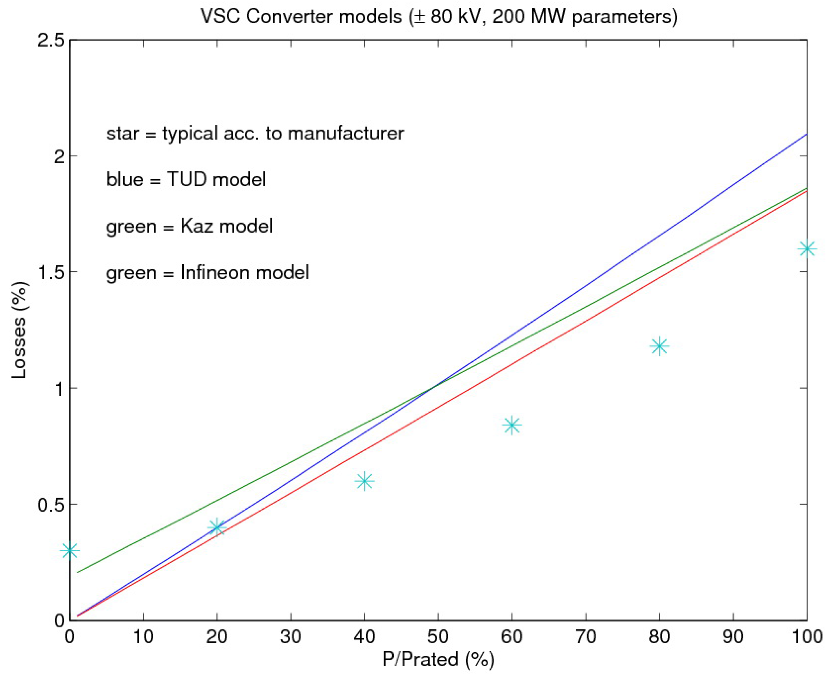
| PWM | PWM rect Kaz, TUD, Inf | IGBT rectifier Kazmierkovski, TUD, Infineon model |
| PWM inv Kaz, TUD, Inf | IGBT inverter Kazmierkovski, TUD, Infineon model | |
| Chopper | Step-up chopper | DC-DC transformer |
| Statcom | Statcom TUD | IGBT inverter TU Delft model modified as Statcom |
| Availability | Availability | power reduction due to component failure |
| Control | Qfeedback | sets the reactive power of individual turbines |
3. Wind farm electrical system evaluation
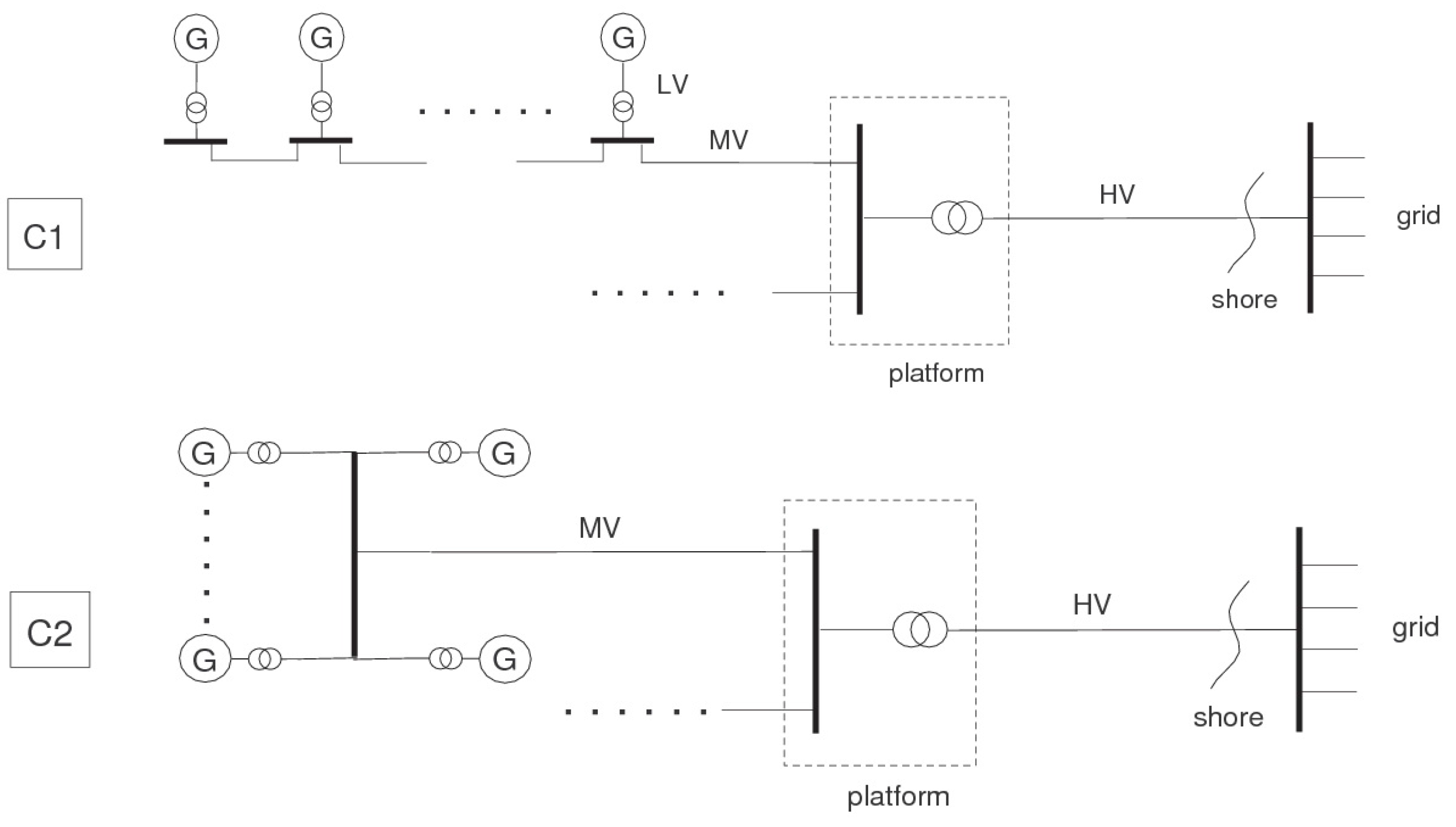
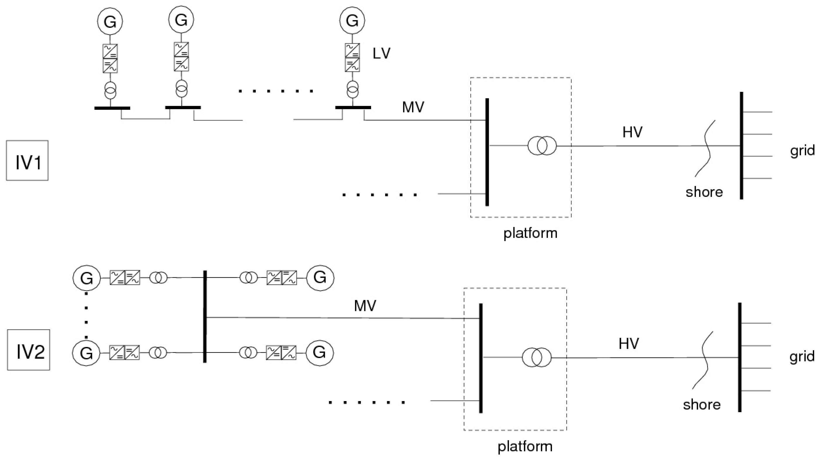
3.1. Wind farm electrical system description


- a wind farm size of 200 MW;
- a wind turbine size of 5 MW;
- the length of the cable to shore is 100 km;
- two wind farm layouts: strings of five turbines (daisy chain) or stars of nine turbines connected to turbine number 10 at the center;
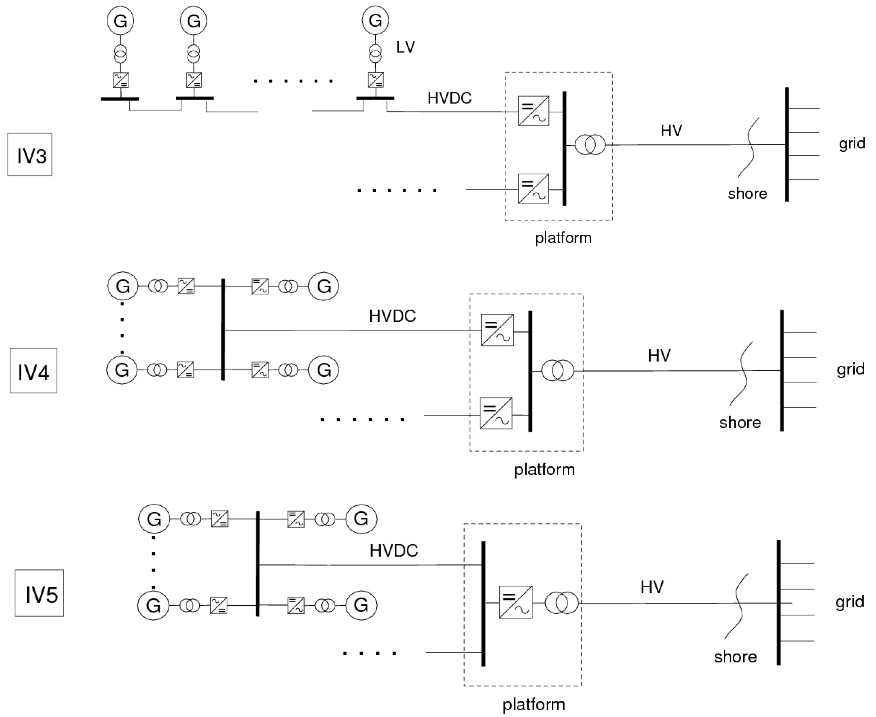
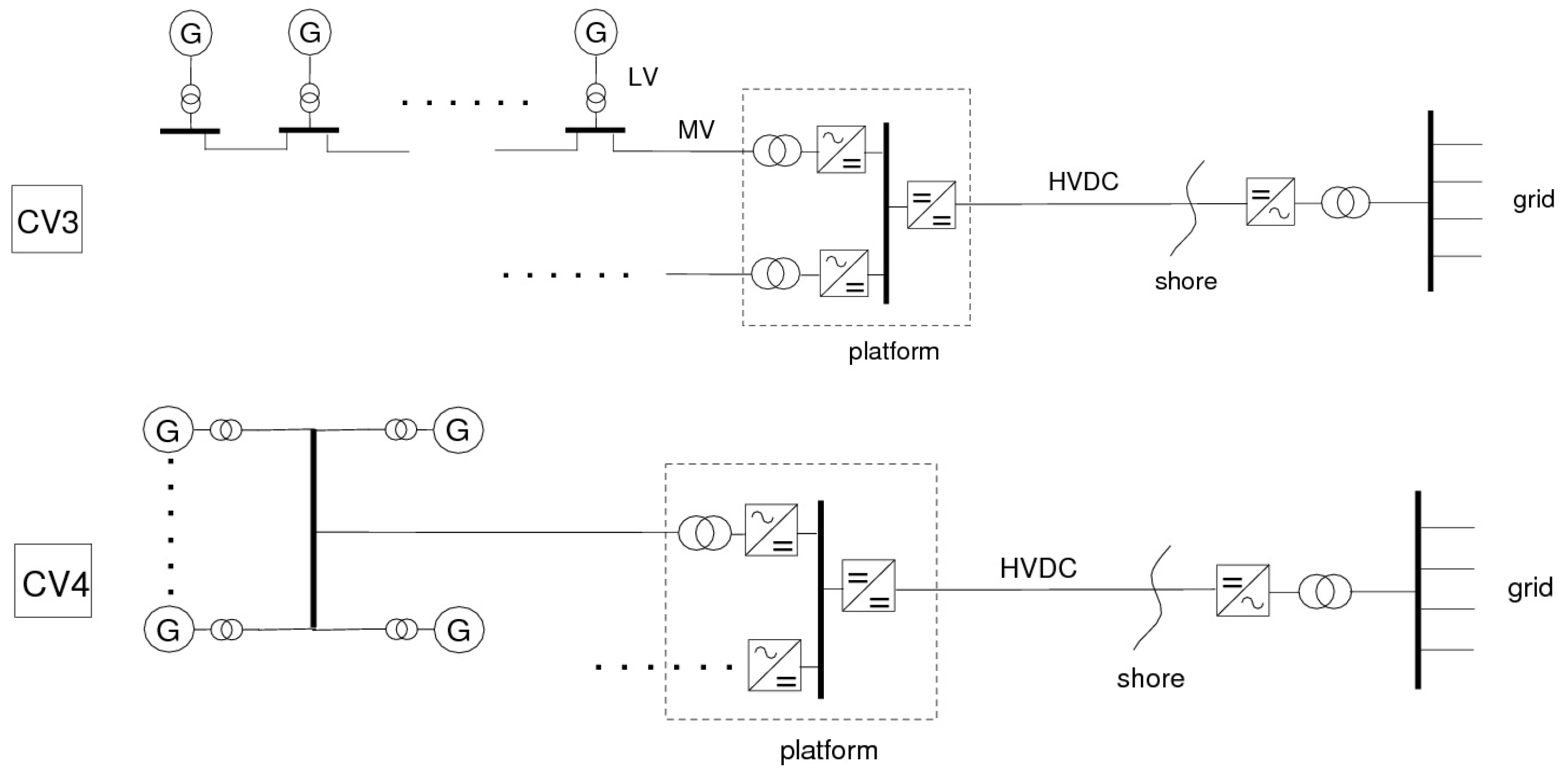
- four types of system operation:
- −
- constant speed, all AC system (C1 and C2);
- −
- individual variable speed with AC or DC connection to shore (IV1-IV5);
- −
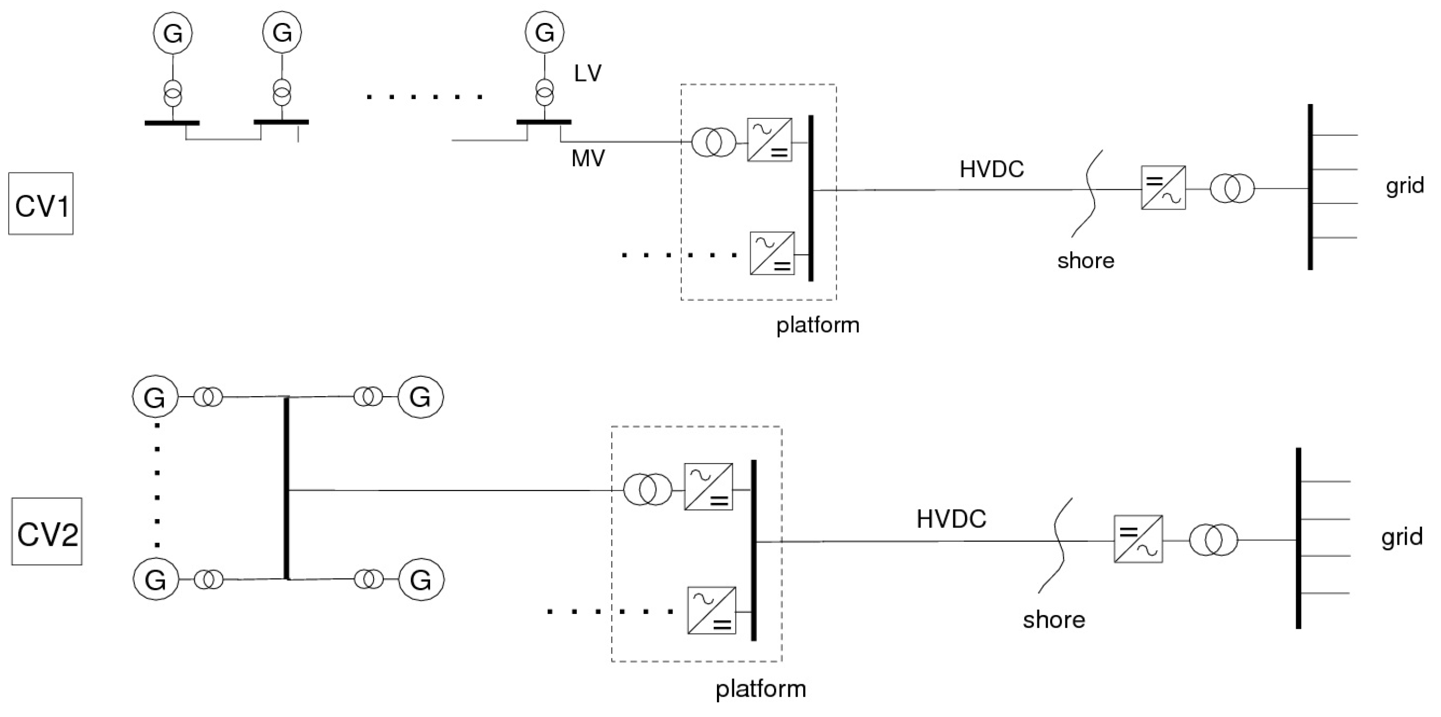
- cluster variable speed with a number of turbines AC connected to a single rectifier (CV1-CV4);
- −
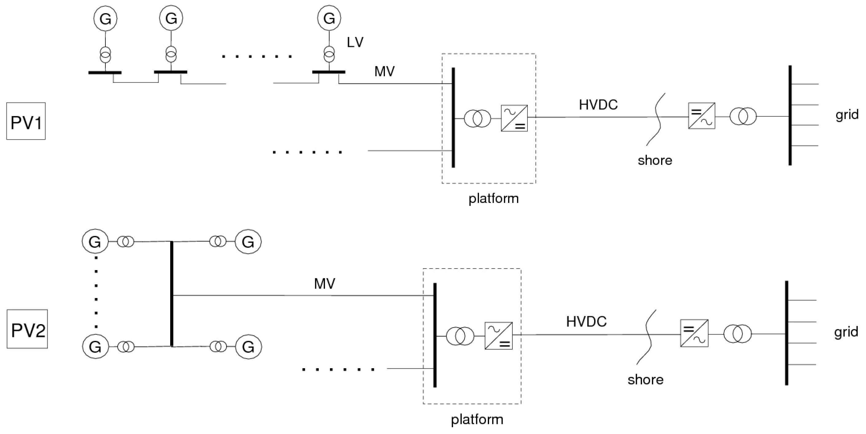
- park variable speed: all turbines in the farm are connected to a single AC-DC converter with a DC connection to shore (PV1 and PV2);
- in configuration CV3 and CV4 a chopper is used to increase the DC voltage of the DC connection to shore.
- a wind farm life time of 12 years;
- a nominal interest rate of 7% and an inflation of 1.5%;
- the investment costs and the LPC do not include the turbine costs, only the costs of the electrical components connecting the turbines in the farm to the HV grid on land are included;
- the LPC does not include operation and maintenance costs.
- an average wind speed of 9.7 m/s;
- a Weibul factor k = 2.08.
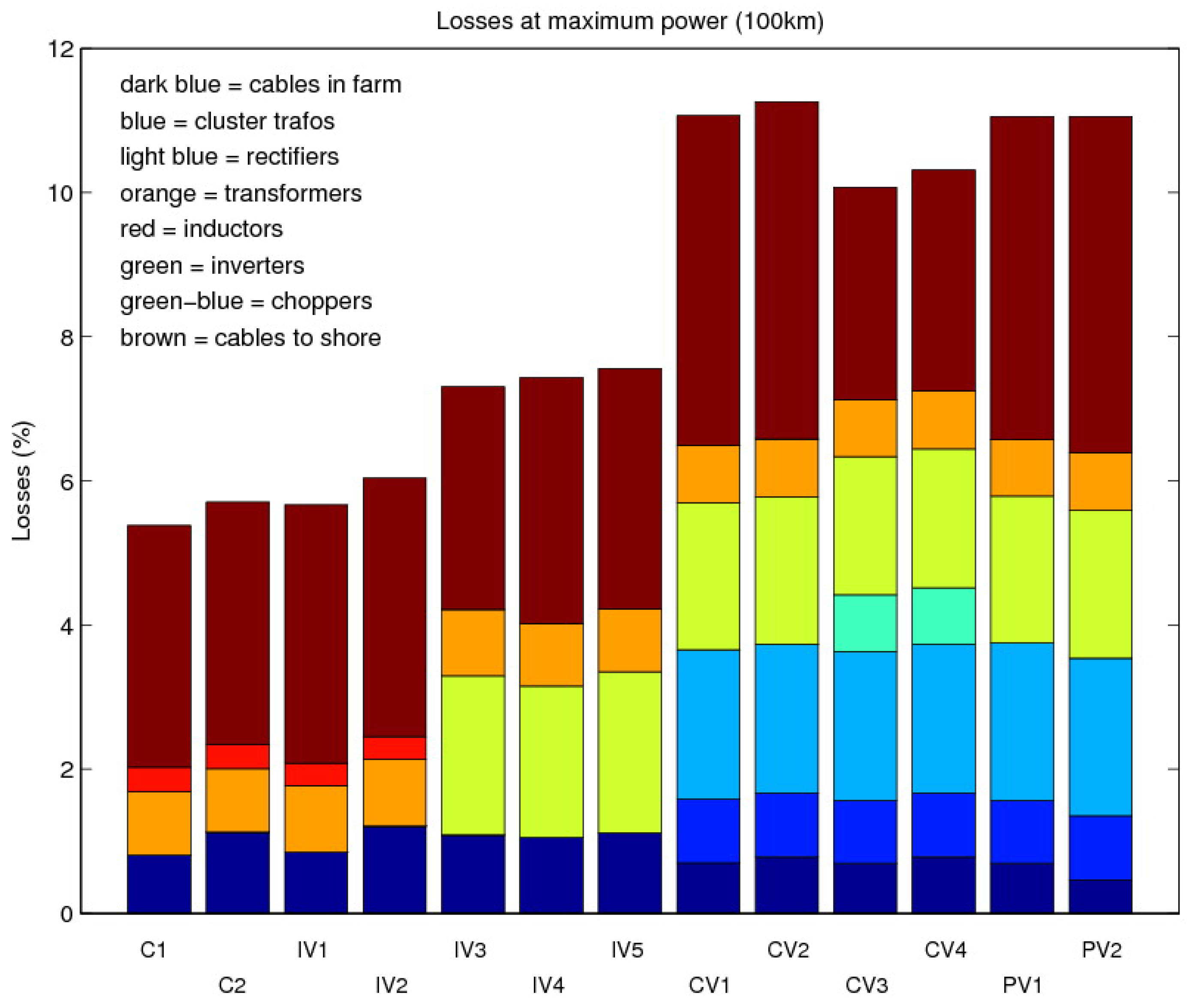
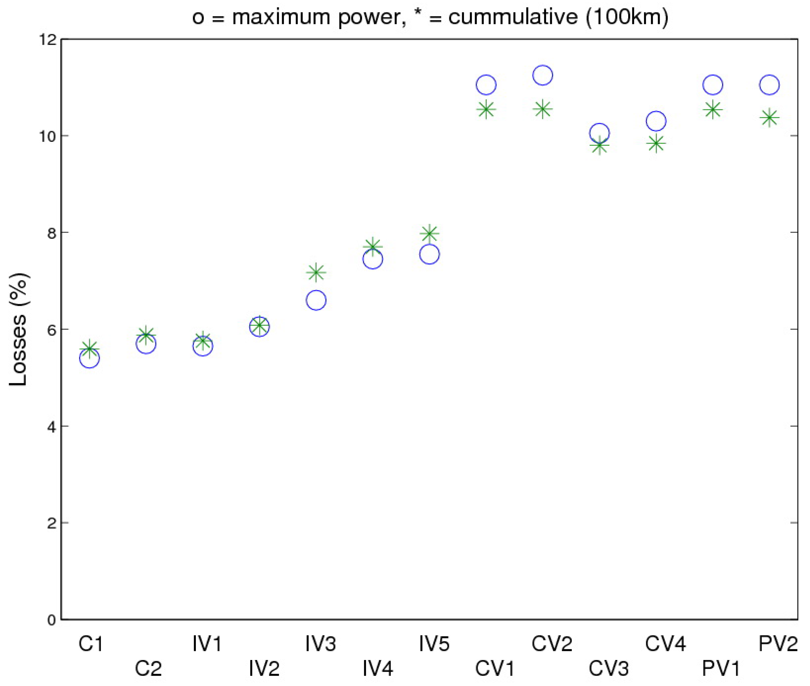
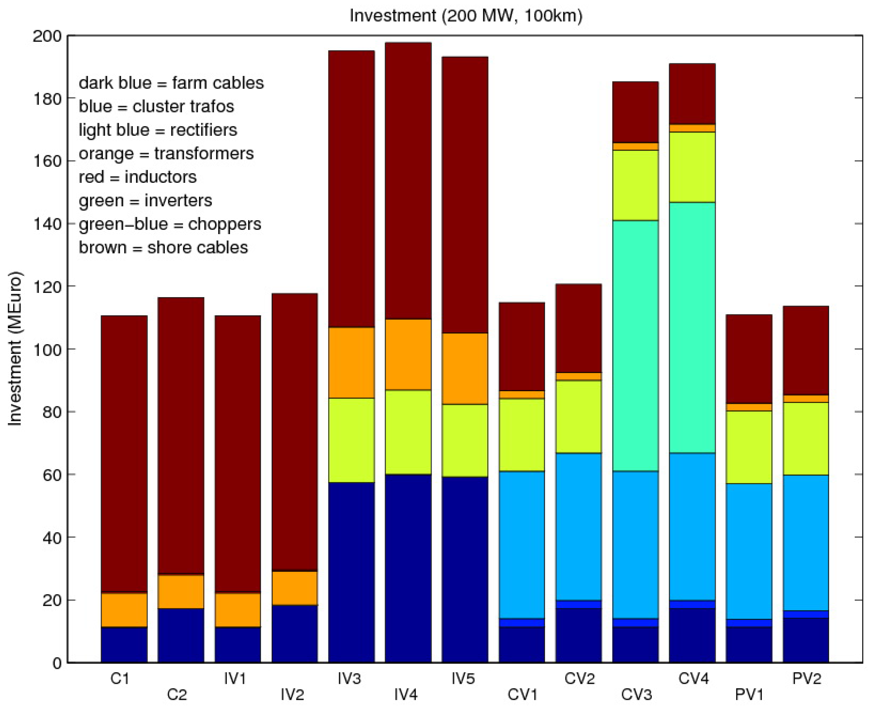
3.2. Wind farm electrical system evaluation results
| Voltage | Current | Power | Reactive Power | Losses | Relative losses | |
|---|---|---|---|---|---|---|
| (kV) | (A) | (MW) | (Mvar) | (MW) | (-) | |
| C1 | 133 | 902 | 189.2 | 87.3 | 10.8 | 0.0538 |
| C2 | 133 | 903 | 188.6 | 86.6 | 11.4 | 0.0570 |
| IV1 | 128 | 914 | 188.7 | 74.0 | 11.3 | 0.0566 |
| IV2 | 127 | 915 | 187.9 | 73.3 | 12.1 | 0.0604 |
| IV3 | 137 | 907 | 185.4 | 110.0 | 14.6 | 0.0730 |
| IV4 | 132 | 993 | 185.1 | 132.2 | 14.9 | 0.0743 |
| IV5 | 133 | 980 | 184.9 | 129.9 | 15.1 | 0.0755 |
| CV1 | 142 | 725 | 177.9 | −12.2 | 22.1 | 0.1106 |
| CV2 | 140 | 733 | 177.5 | −12.4 | 22.5 | 0.1125 |
| CV3 | 128 | 813 | 179.9 | −12.0 | 20.1 | 0.1007 |
| CV4 | 125 | 829 | 179.4 | −12.5 | 20.6 | 0.1031 |
| PV1 | 143 | 718 | 177.9 | −11.9 | 22.1 | 0.1104 |
| PV2 | 141 | 732 | 177.9 | −12.4 | 22.1 | 0.1105 |


| Energy produced | Energy losses | Relative losses | |
| (MWh/y) | (MWh/y) | (-) | |
| C1 | 938940 | 55638 | 0.0593 |
| C2 | 936141 | 58437 | 0.0624 |
| IV1 | 937275 | 57303 | 0.0611 |
| IV2 | 934051 | 60527 | 0.0648 |
| IV3 | 916412 | 78171 | 0.0853 |
| IV4 | 917979 | 76611 | 0.0835 |
| IV5 | 915285 | 79299 | 0.0866 |
| CV1 | 889662 | 104875 | 0.1179 |
| CV2 | 889597 | 104944 | 0.1180 |
| CV3 | 897070 | 97480 | 0.1087 |
| CV4 | 896641 | 97913 | 0.1092 |
| PV1 | 889702 | 104835 | 0.1178 |
| PV2 | 891353 | 103189 | 0.1158 |
| Investment | Energy produced | Specific investment | LPC | |
| (MEuro) | (MWh/y) | (MEuro/MW) | (Euro/kWh) | |
| C1 | 110.6 | 935227.7 | 0.5530 | 0.0137 |
| C2 | 116.4 | 932445.8 | 0.5820 | 0.0144 |
| IV1 | 110.6 | 933371.3 | 0.5530 | 0.0137 |
| IV2 | 117.6 | 930167.4 | 0.5881 | 0.0146 |
| IV3 | 195.0 | 915328.5 | 0.9751 | 0.0246 |
| IV4 | 197.6 | 917680.2 | 0.9881 | 0.0249 |
| IV5 | 193.1 | 913794.9 | 0.9655 | 0.0244 |
| CV1 | 114.8 | 884801.7 | 0.5742 | 0.0150 |
| CV2 | 120.6 | 886043.7 | 0.6031 | 0.0157 |
| CV3 | 185.1 | 892104.8 | 0.9256 | 0.0240 |
| CV4 | 190.9 | 892962.7 | 0.9546 | 0.0247 |
| PV1 | 110.9 | 884866.5 | 0.5544 | 0.0145 |
| PV2 | 113.6 | 887782.1 | 0.5680 | 0.0148 |
4. Conclusions and recommendations
- The user friendly EeFarm-II program for wind farm electrical and economic evaluations has been described and demonstrated by comparing thirteen different electrical systems for a 200 MW wind farm at 100 km from shore;
- For this wind farm size and distance, two options have the best performance, expressed as costs of one kWh averaged over the lifetime of the wind farm: the AC system and the system with a DC connection to shore;
- The losses of the DC systems are considerably higher than for the AC systems. The losses in the DC cables to shore can be decreased considerably however by increasing the voltage, which was relatively low (±80 kV). For long AC cables increasing the voltage is problematic due to the increasing capacitive current;
- Only losses and costs have been considered in this evaluation. Systems with PWM converters do have a number of advantages which have not been taken into account, for example better controllability and reactive power production or consumption. Therefore it is recommended to develop a method to take more aspects, positive as well as negative, into account in future wind farm electrical system evaluations.
Acknowledgements
References
- Fichaux, N.; Wilkes, J. Oceans of Opportunity Harnessing Europe Largest Domestic Energy Resource; European Wind Energy Association: Brussels, Belgium, September 2009. [Google Scholar]
- Pierik, J.T.G.; Axelsson, U.; Eriksson, E.; Salomonsson, D. EeFarm II: Description, testing and application. ECN 2009. ECN-E-09-051. [Google Scholar]
- Pierik, J.T.G.; Damen, M.E.C.; Bauer, P.; de Haan, S.W.H. Electrical and control aspects of offshore wind farms. Phase 1: Steady state electrical design, power performance and economic modeling. Volume 1: Project results. ECN 2001. ECN-CX-01-083. [Google Scholar]
- Barberis Negra, N.; Todorovic, J.; Ackermann, T. Loss evaluation of HVAC and HVDC transmission solutions for large offshore wind farms. Electr. Power Syst. Res. 2006, 76, 916–927. [Google Scholar] [CrossRef]
- Axelsson, U. Losses for a typical VSC converter. Personal communication, November 2008. [Google Scholar]
© 2010 by the authors; licensee Molecular Diversity Preservation International, Basel, Switzerland. This article is an open access article distributed under the terms and conditions of the Creative Commons Attribution license http://creativecommons.org/licenses/by/3.0/.
Share and Cite
Pierik, J.; Axelsson, U.; Eriksson, E.; Salomonsson, D.; Bauer, P.; Czech, B. A Wind Farm Electrical Systems Evaluation with EeFarm-II. Energies 2010, 3, 619-633. https://doi.org/10.3390/en3040619
Pierik J, Axelsson U, Eriksson E, Salomonsson D, Bauer P, Czech B. A Wind Farm Electrical Systems Evaluation with EeFarm-II. Energies. 2010; 3(4):619-633. https://doi.org/10.3390/en3040619
Chicago/Turabian StylePierik, Jan, Urban Axelsson, Emil Eriksson, Daniel Salomonsson, Pavol Bauer, and Balazs Czech. 2010. "A Wind Farm Electrical Systems Evaluation with EeFarm-II" Energies 3, no. 4: 619-633. https://doi.org/10.3390/en3040619
APA StylePierik, J., Axelsson, U., Eriksson, E., Salomonsson, D., Bauer, P., & Czech, B. (2010). A Wind Farm Electrical Systems Evaluation with EeFarm-II. Energies, 3(4), 619-633. https://doi.org/10.3390/en3040619