Gas Turbine Combustion and Ammonia Removal Technology of Gasified Fuels

Abstract
:1. Introduction


| Fuel | BFGa | COGb | LDGc | Gasified fuel | |||||||||
|---|---|---|---|---|---|---|---|---|---|---|---|---|---|
| Resource | Coald | Heavy residue | OrimulsionTM | ||||||||||
| Coal type or mine | 1 | -g | 2 | 3 | 4 | 5 | 6 | 7 | |||||
| Gasifier type | Fixed | Fluidized | Entrained | Entrained | Entrained | ||||||||
| Coal supply | Dry | Dry | Dry | Slurry | |||||||||
| Developer | BGL[4] | BC[5] | IGC[6] | Shell[7] | HYCOL[8] | Texaco[9] | Texaco | CRIEPI[11] | |||||
| Oxidizer | O2 | Air | Air | O2 | O2 | O2 | O2 | O2 | |||||
| Composition | |||||||||||||
| CO [%] | 20 | 6 | 75 | 56.4 | 7.9–14.7 | 27.6 | 25.9 | 67.8 | 69.5 | 55.2–59.4 | 40.9 | 51.7 | 43.5 |
| H2 [%] | 3 | 56 | - f | 25.6 | 13.2–15.0 | 9.4 | 10.9 | 28.8 | 31.0 | 31.1–33.7 | 29.9 | 43.1 | 42.2 |
| CH4 [%] | - f | 30 | - g | 6.6 | 1.5–2.8 | 0.5 | 1.4 | 0.01 | 0.03 | 1.0–2.0 | 0.1 | 0.2 | 0.4 |
| CO2 [%] | 20 | - f | 13 | 2.8 | 10.0–12.0 | 5.4 | 6.7 | 2.3 | 1.0 | 7.6–10.4 | 9.5 | 3.2 | 11.8 |
| H2O [%] | - f | - f | - g | - g | 11.5–18.4 | - g | - g | - i | - i | - g | 12.3 | - i | - i |
| NH3 [ppm] | - f | - f | - g | - g | 500–1000 | 1000 h | 100 | 600 | - g | - g | - g | - g | |
| H2S+COS[ppm] | - f | - f | - g | 20 | - g | 714 | 404 | 1.1% | 0.14% | - g | - g | 1.6% | 1.35% |
| Others[%] | N2 | C2H2 etc. | O2, N2 | 8.6 | 45.9– 47.3 | 56.1 | 54.2 | - g | - g | - g | 7.3 | 0.2 | 0.75 |
| CO/H2 mole ratio | 7 | 0.1 | - f | 2.2 | - g | 2.9 | 2.4 | 2.1 | 2.4 | 1.6–1.9 h | 1.4 | 1.2 | 1.0 |
| HHV[MJ/m3] | 2.9 | 21 h | 9.5 h | 13.0 | - g | 4.9 | 5.2 | 12.2 | 12.5 | 12.0 h | 9.0 | 12.1 i | 11.0 i |
| LHV [MJ/m3] | 2.9 | 19 h | 9.5 h | 12.0 | 3.6–4.1 | 3.6 | 3.9 | 11.7 | 11.9 | 11.3 h | 7.4 | 11.3 i | 10.2 i |
| Resource | Wood | Wastek | RDFm | Black Liquor | |||||||||||||
|---|---|---|---|---|---|---|---|---|---|---|---|---|---|---|---|---|---|
| Feedstock type | Planer chip | Mill ends | Planer Bark briquette | Waste chip | Pellet | Round timber chip | Chip | ||||||||||
| Moisture content[%] | 13.3 | 45 | 27 | 15 | 8 | 9 | -g | -g | -g | -g | 15 – 40 | -f | -f | -g | |||
| Gasifier type | Kiln | Fixed-bed down-draft | Fluidized | Entrained | |||||||||||||
| Developer | Chugairo Co., Ltd. | Kawasaki Heavy Ind | Indian Inst. Sci. | Lurgi | Guessing | CHOREN Ind. | Tampella [13] | Chemrec [14] | |||||||||
| Oxidizer | Dry | Dry+O2 | Air | Air | Air | O2 | Air+steam | Air | O2 | Air+steam | Air | Air+O2 | O2 | ||||
| distillation | |||||||||||||||||
| Composition | |||||||||||||||||
| CO [%] | 36.1 | 26.0 | 9.7 | 14.6 | 20.6 | 19.8 | 17.9 | 19 | 20 | 46 | 25 | 22 | 40 | 8.0–15.0 | 6 | 30 | 38.08 |
| H2 [%] | 20.2 | 30.1 | 11.2 | 14.3 | 16.7 | 15.2 | 14.5 | 16 | 10 | 13 | 40 | 22 | 40 | 8.0–12.0 | 1.6 | 22 | 39.17 |
| CH4 [%] | 16.6 | 2.5 | 1.2 | 1.4 | 1.3 | 1.9 | 1.3 | 12 | 5 | 10 | 10 | - g | - g | 4.0–8.0 | 0.9 | 0.4 | 1.34 |
| CO2 [%] | 15.8 | 17.9 | - g | - g | - g | - g | - g | 2 | 14 | 23 | 22 | 11 | 20 | 13.0–18.0 | 12.4 | 4.1 | 19.05 |
| H2O [%] | - g | - g | 1.3 | 0.7 | 2.8 | 0.9 | 1.8 | - g | - g | - g | - g | - g | - g | 7.0–15.0 | 23.4 | 5.9 | 0.18 |
| N2 [%] | 5.6 | 17.9 | 56.9 | 53.5 | 50.2 | 49.9 | 52.1 | 51 | 51 | 8 | - g | 45 | - g | - g | - f | - f | 0.24 |
| NH3 [ppm] | - g | - g | - g | - g | - g | - g | - g | - g | - g | - g | - g | - g | - g | - g | - f | - f | - g |
| H2S+COS[ppm] | - g | - g | - g | - g | - g | - g | - g | - g | - g | - g | - g | - g | - g | - g | - f | - f | 19,400 |
| Others[%] | 5.7 | 5.6 | - g | - g | - g | - g | - g | - g | - g | - g | - g | - g | - g | - g | N2, C2H4 etc. N2 | - g | |
| Tar [mg/m3] | 25,000 | 5 | 261 | 438 | 95 | 400 | 103 | 100 | - g | - g | - g | - n | - n | - g | - f | - f | 115 |
| Dust [mg/m3] | 11,000 | <2 | - g | - g | - g | - g | - g | - g | - g | - g | - g | - g | - g | <5 | - f | - f | - g |
| CO/H2 mole ratio | 1.8 | 0.9 | 0.9 | 1.0 | 1.2 | 1.2 | 1.2 | 1.2 | 2 | 3.5 | 0.6 | 1.0 | 1.0 | - g | 3.8 | 1.4 | 1.0 |
| HHV[MJ/m3] | - g | - g | - g | - g | - g | - g | - g | - g | - g | - g | - g | - g | - g | - g | 1.8 | 6.8 | 10.3 |
| LHV [MJ/m3] | 15.2 | 7.5 | 3.1 | 4.0 | 5.0 | 5.1 | 4.5 | 5.4 | 6.3 | 11.7 | 13.8 | 6.3 | 10.5 | 4 - 6 | 1.2 | 6.2 | 9.5 |
2. Background of IGCC Development in the World


2.1. Progress in IGCC developments worldwide
- (1)
- Air-blown gasifier + hot/dry type synthetic gas cleanup method.
- (2)
- Oxygen-blown gasifier + wet type synthetic gas cleanup method.
- (3)
- Oxygen-blown gasifier + hot/dry type synthetic gas cleanup method.
2.2. Subjects of gas turbine combustors for IGCCs
| Synthetic gas cleanup | |||
|---|---|---|---|
| Wet type | Hot/Dry type | ||
| Gasification agent | Air |
|
|
| O2 |
|
| |
2.3. De-NOx technologies of gas turbine combustors for IGCCs
2.3.1. Low-NOx combustion technology
2.3.2. Ammonia removal technology from gasified fuels
3. Basic Investigation of De-NOx Technologies for IGCCs
3.1. Low-NOx combustion technologies
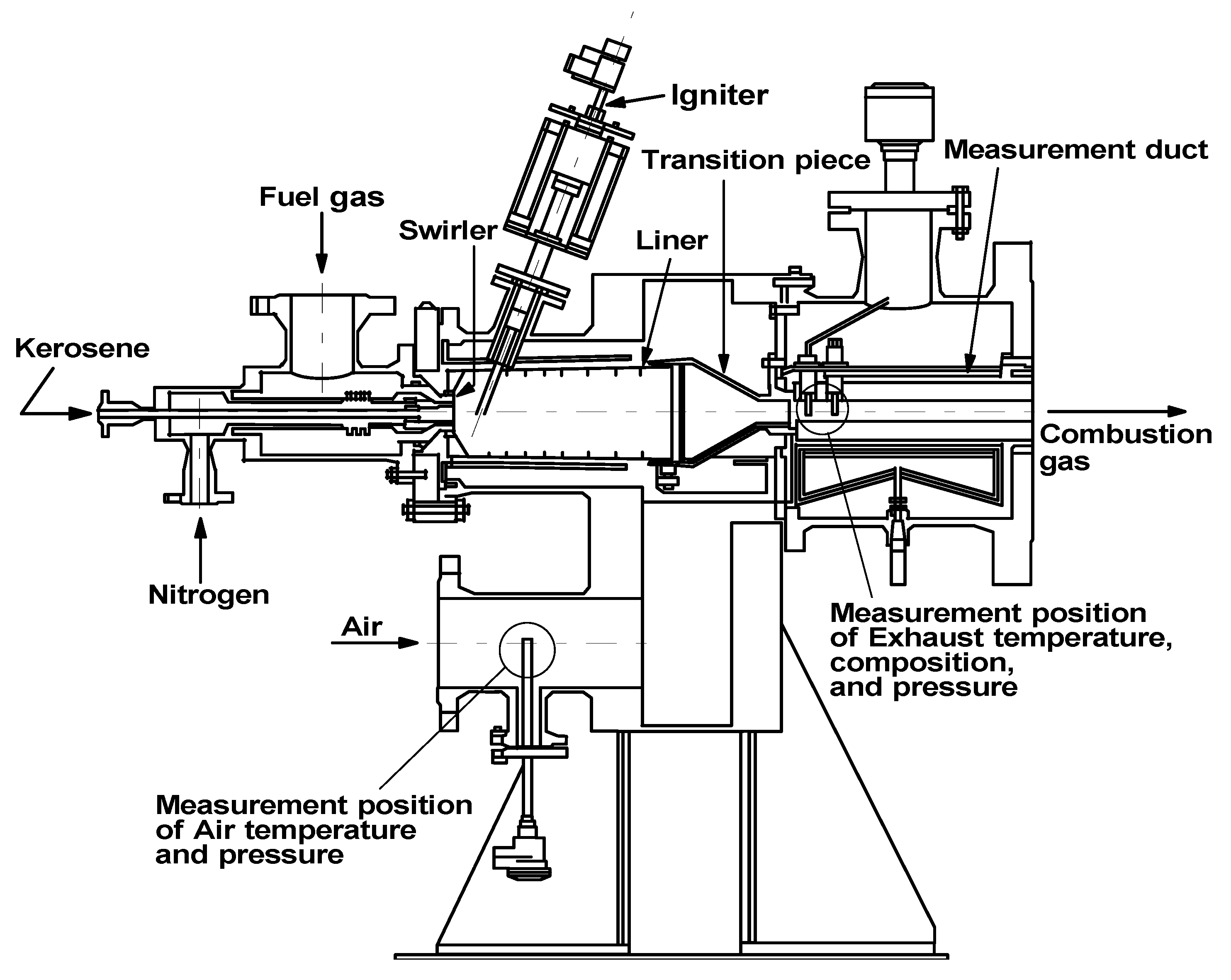
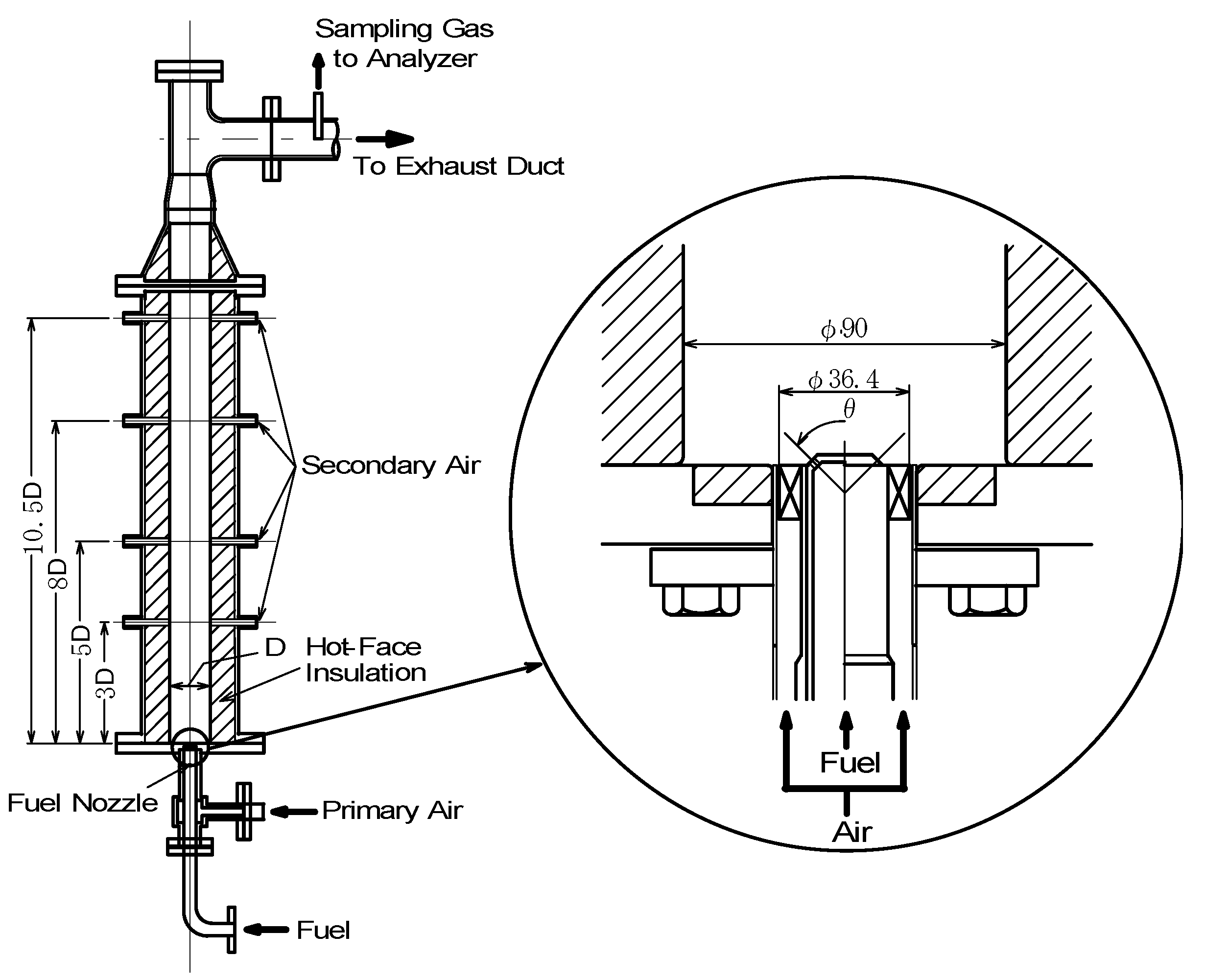
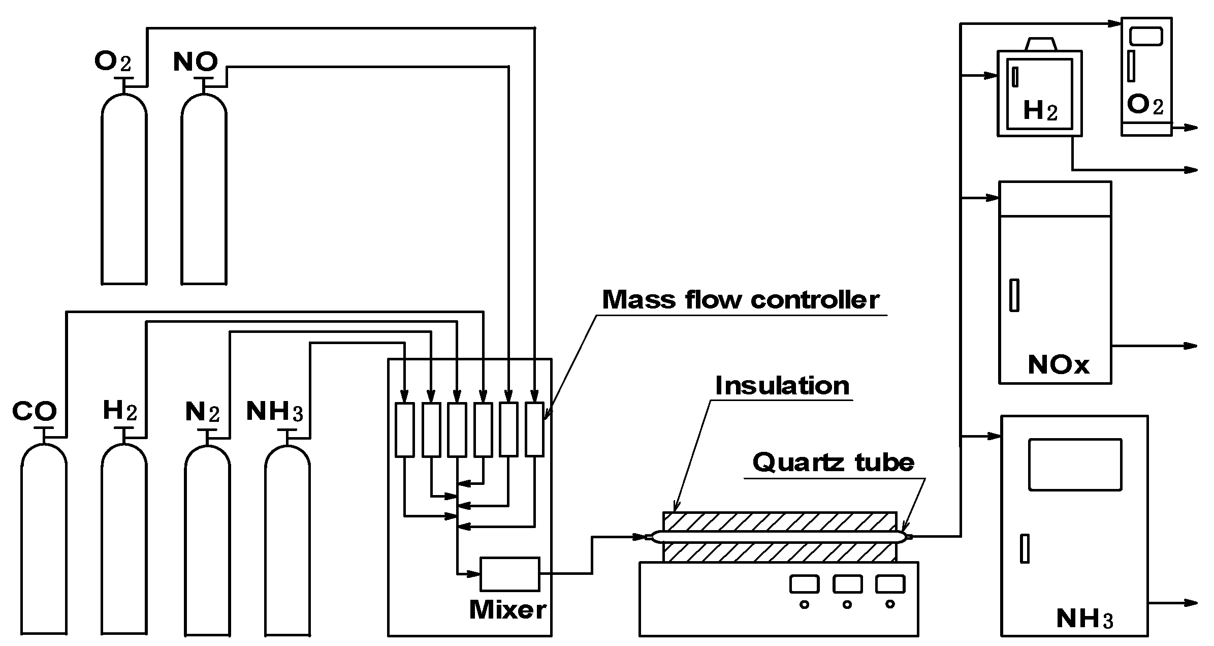
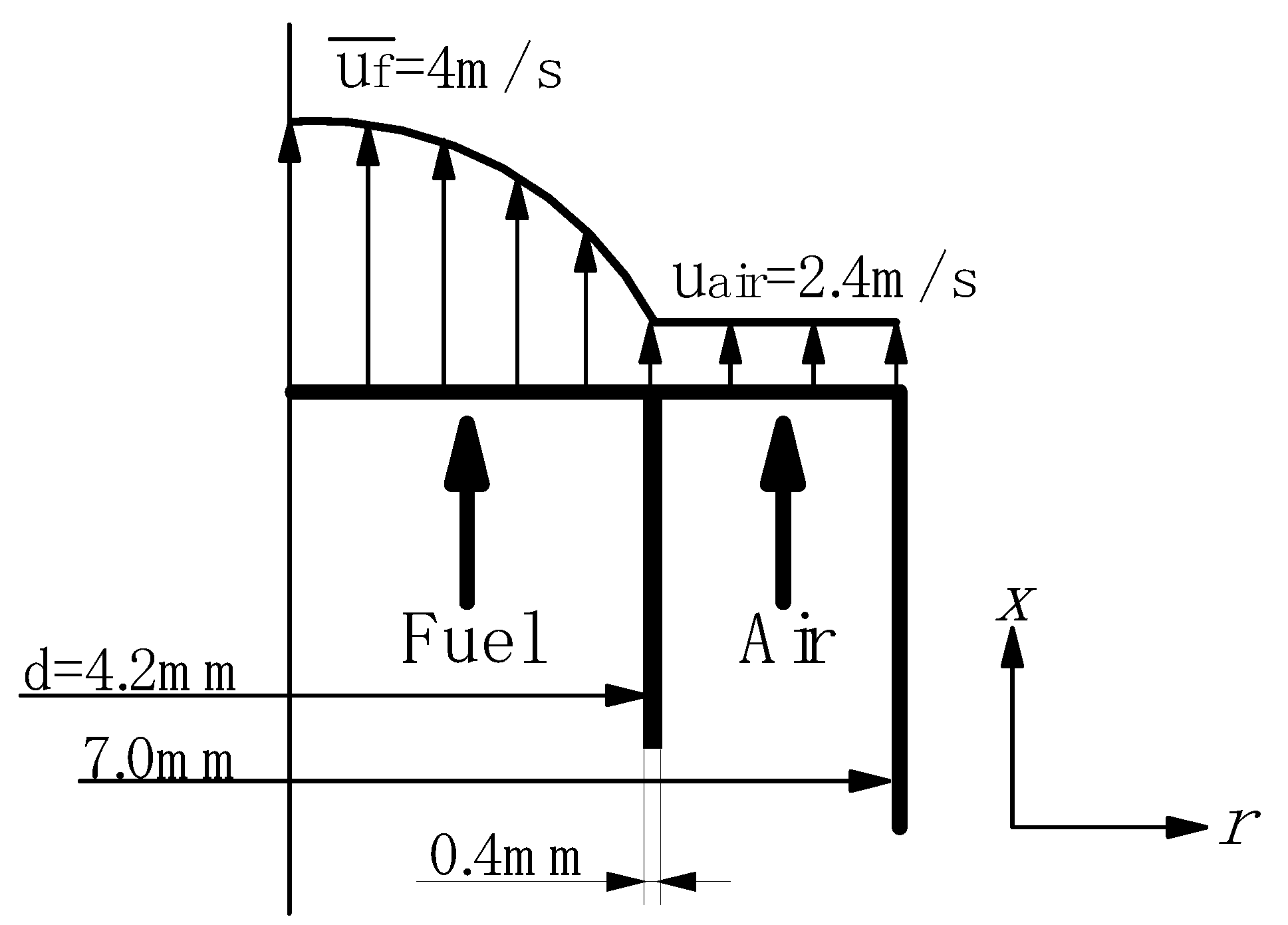
3.1.1. Experimental device and methods of small diffusion burner
Experimental device

Supplied fuels and test conditions
| Fuel properties/Conditions | Fuel standard conditions | ||||||
|---|---|---|---|---|---|---|---|
| Constituent | |||||||
| CO [vol%] | 24.3~13.3 | 17.3 | 10.4 | 16~70 | 23.1 | 46.4 | 63.0 |
| H2 [vol%] | 10.4~5.7 | 17.3 | 24.2 | 7~30 | 9.9 | 19.9 | 27.0 |
| CH4 [vol%]*1 | 0~5.0 | 0, (2.6) | 0 | ||||
| CO2 [vol%] | 0 | ||||||
| H2O [vol%] | 0 | ||||||
| NH3 [ppmv] | 0, 1000, (0~3000) | ||||||
| N2 [vol%] | Balance*2 | ||||||
| CO/H2molar ratio | 2.33 | 1.00 | 0.43 | 2.33 (1, 0.43*3) | 2.33 | 2.33 | 2.33 |
| HHV[MJ/m3](at 273 K, 0.1 MPa) | 4.4 | 2.9~12.7 | 4.2 | 8.4 | 11.4 | ||
| LHV[MJ/m3](at 273 K, 0.1 MPa) | 4.2~4.1 | 4.1 | 3.9 | 4.0~12.1 | 4.0 | 8.0 | 10.9 |
| Tfuel [K] | 423, 298 | 633 | |||||
| Tair [K] | 673 | 643 | |||||
| Vfuel [m/s] | 92, 32 | 96 | |||||
| Pressure | Atmospheric pressure condition | ||||||
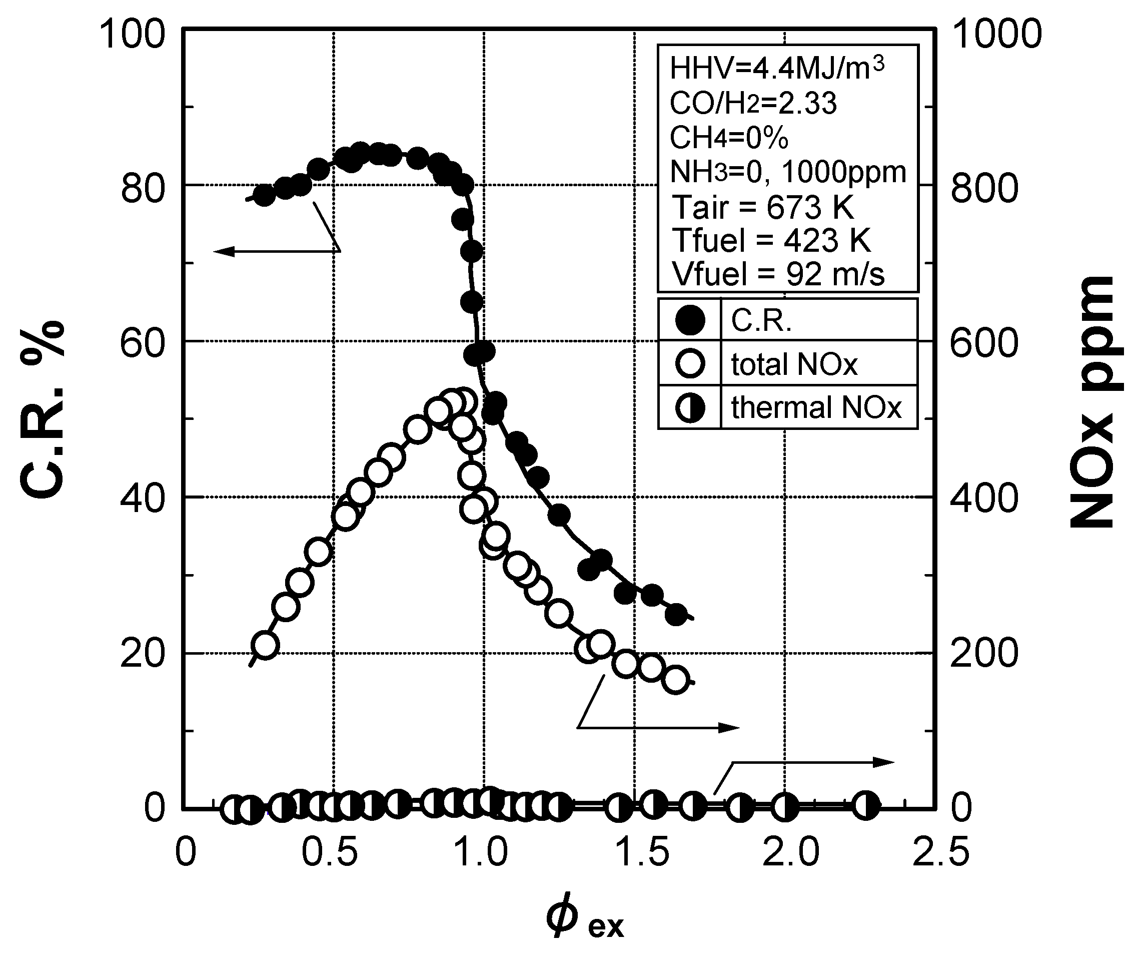
3.1.2. NOx emission characteristics of low-Btu fuel
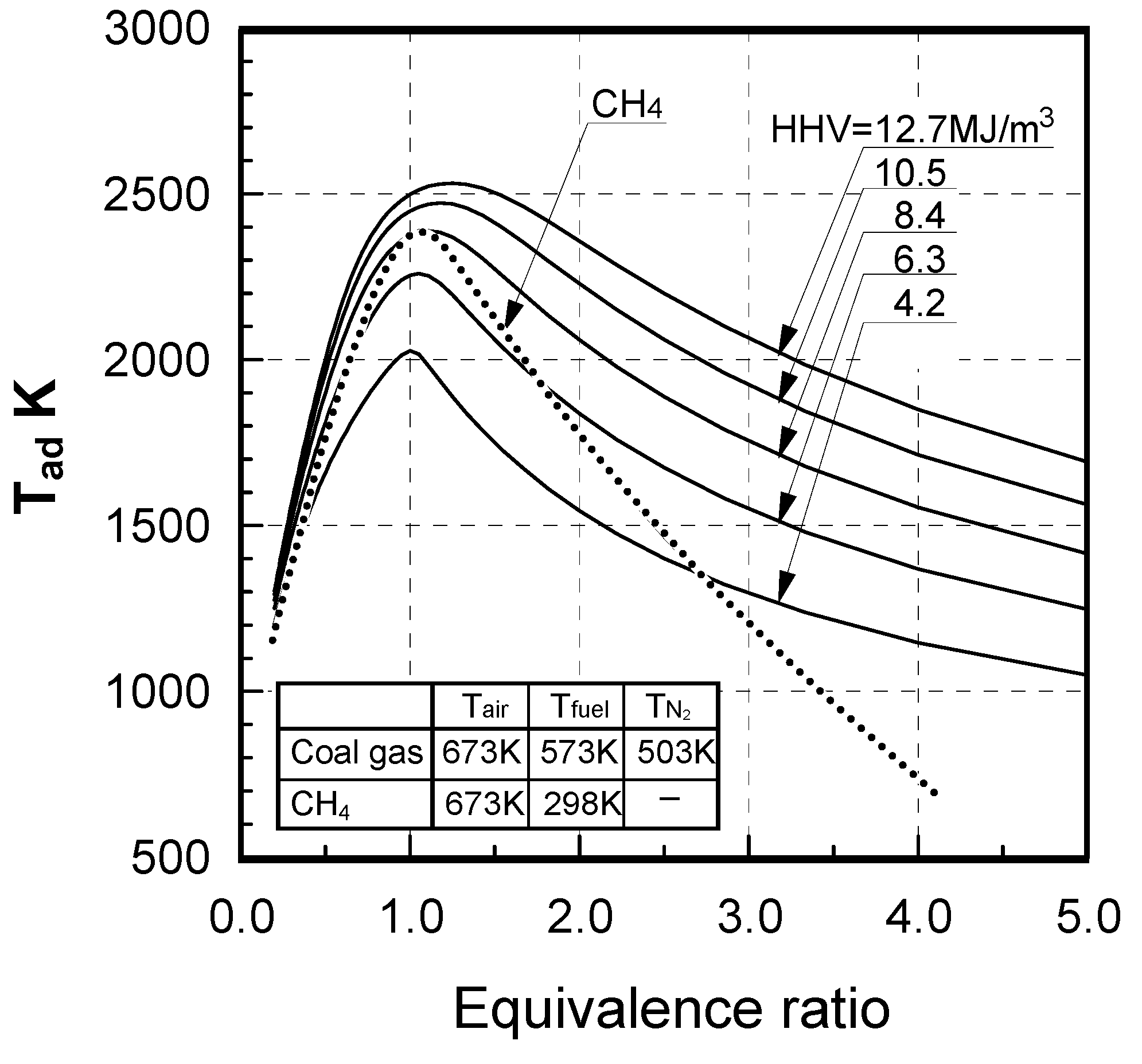
Effects of equivalence ratio

Effects of fuel constituents
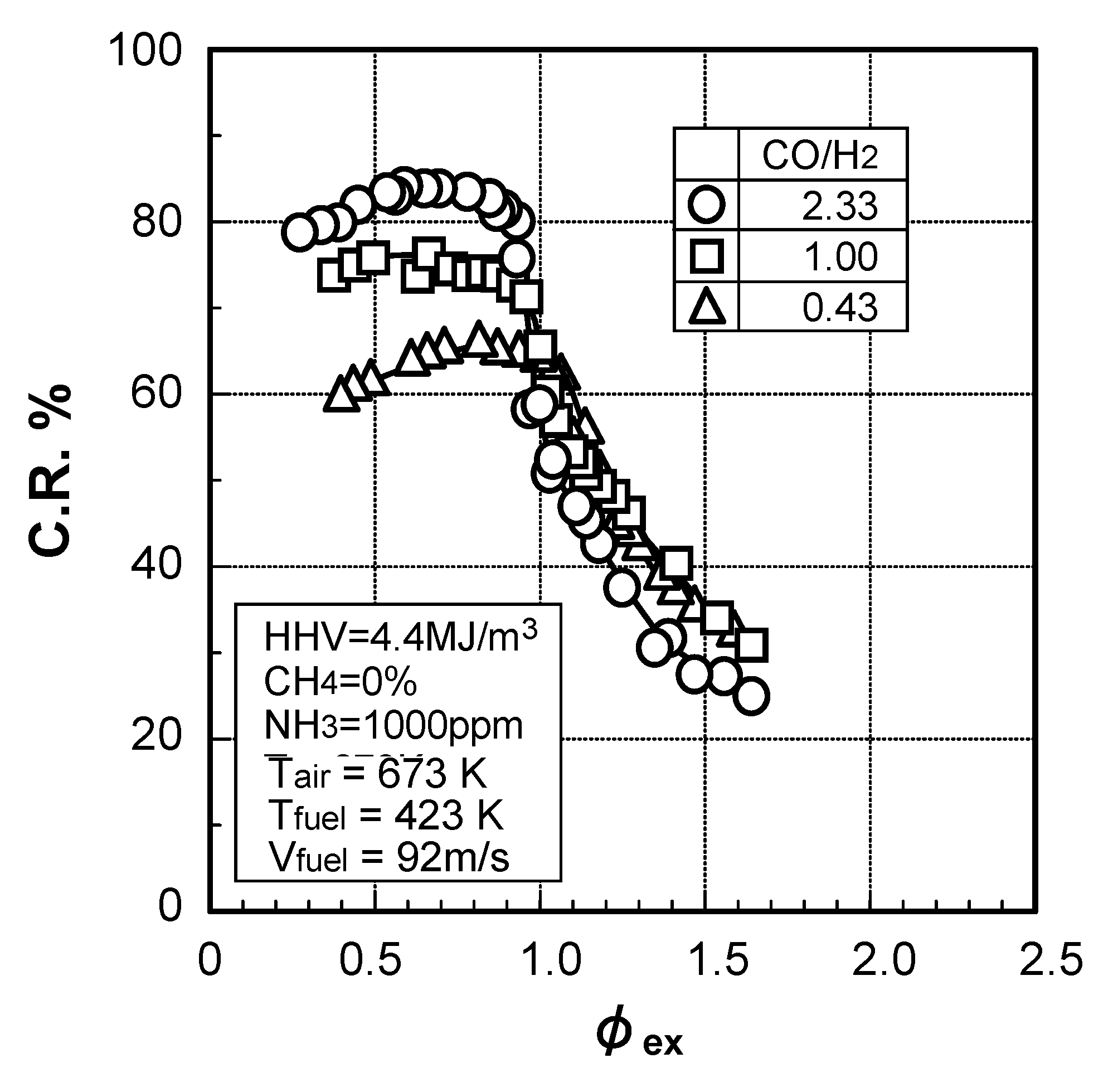
(1) Effect of CO/H2 molar ratio in fuel


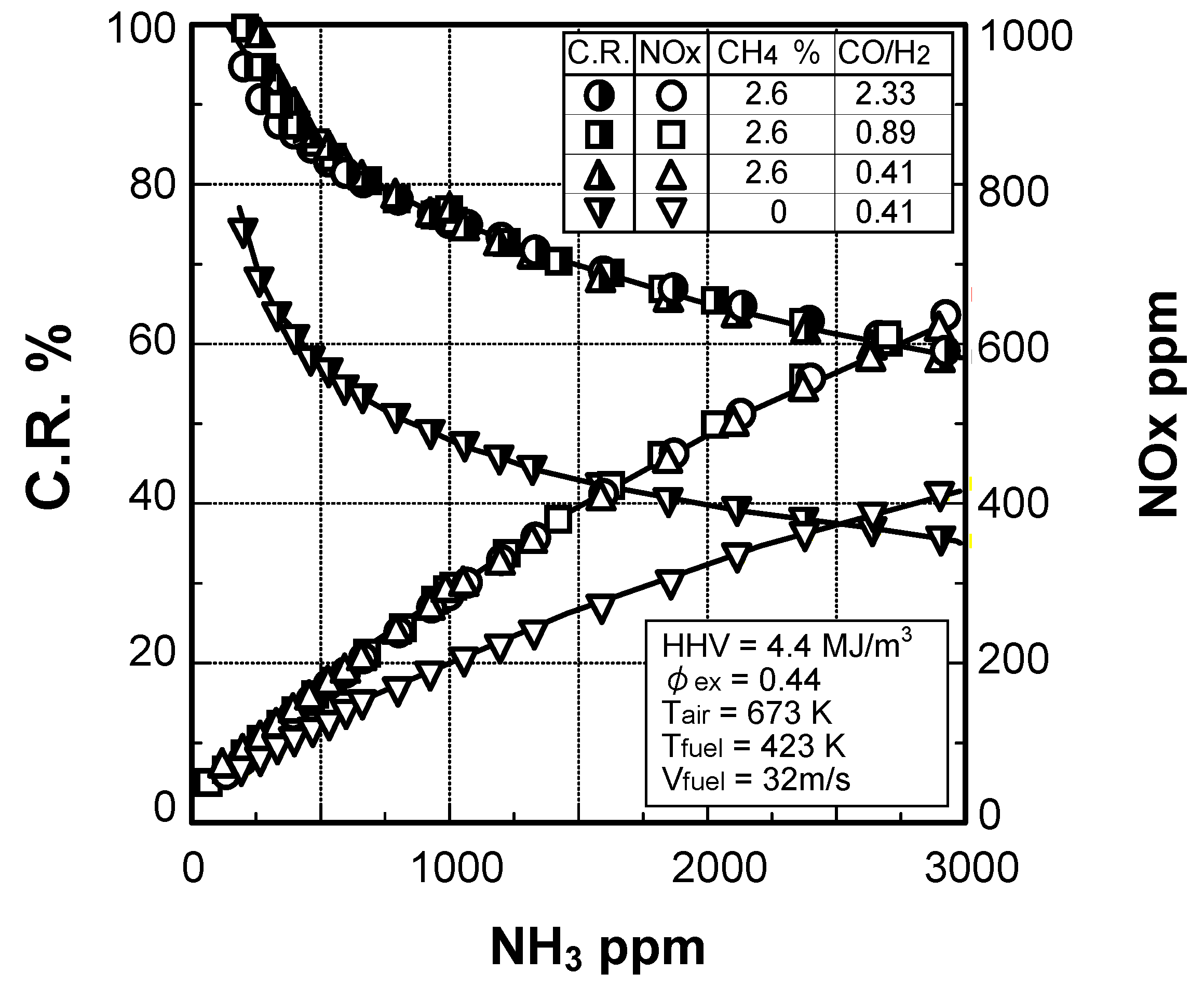
(2) Effect of NH3 concentration in fuel
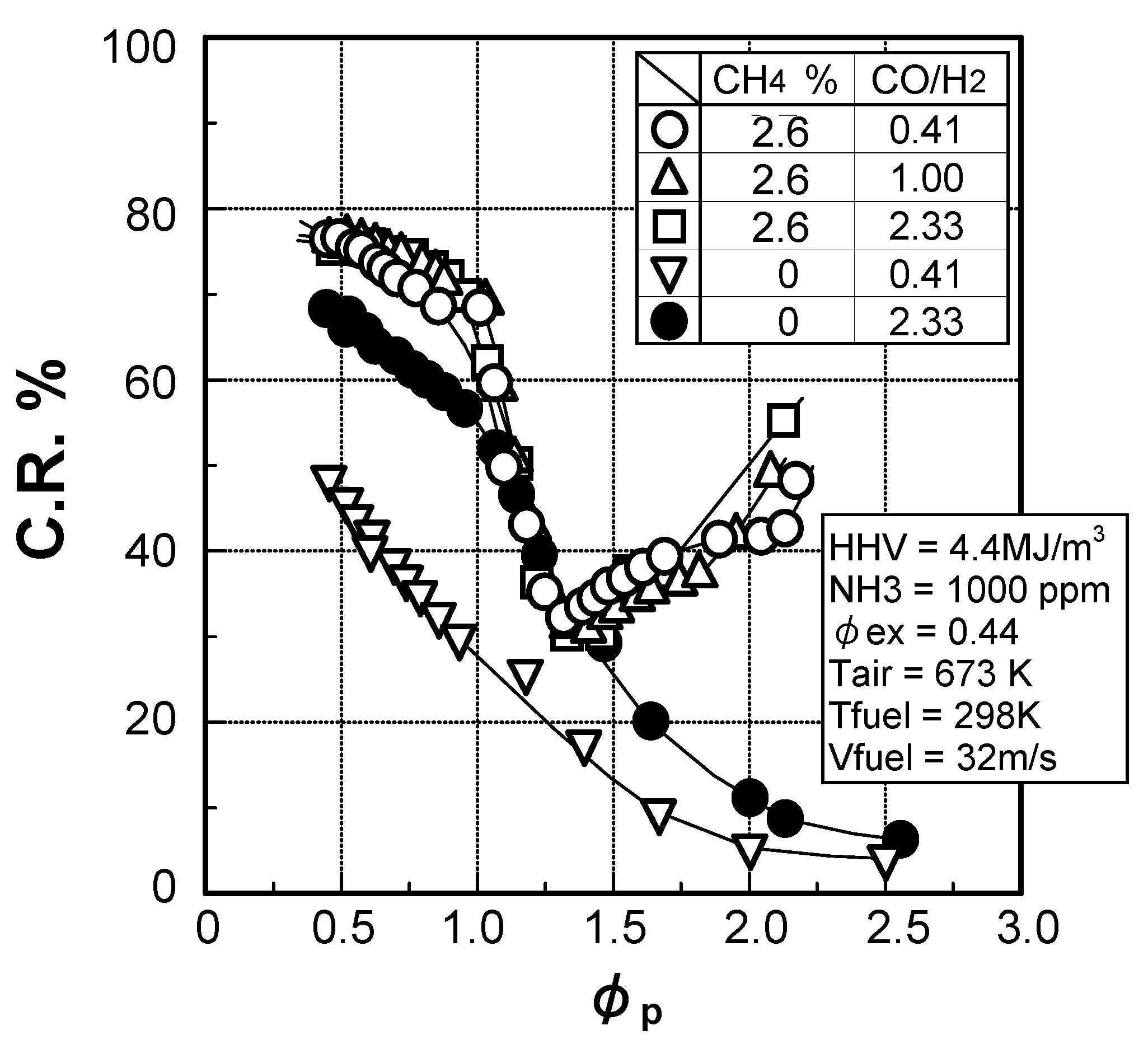
3.1.3. Fuel-NOx emission characteristics in supplied-air staging combustion
Effects of fuel constituents
(1) Effects of CO/H2 molar ratio in fuel

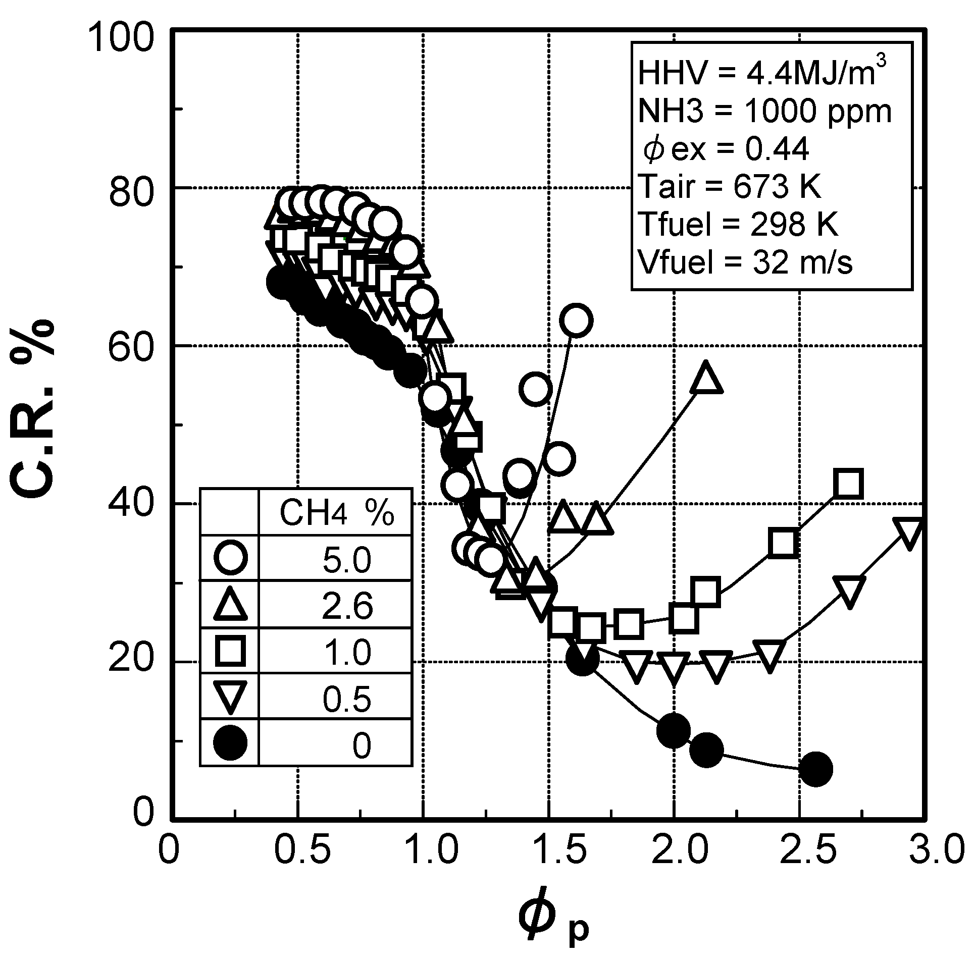
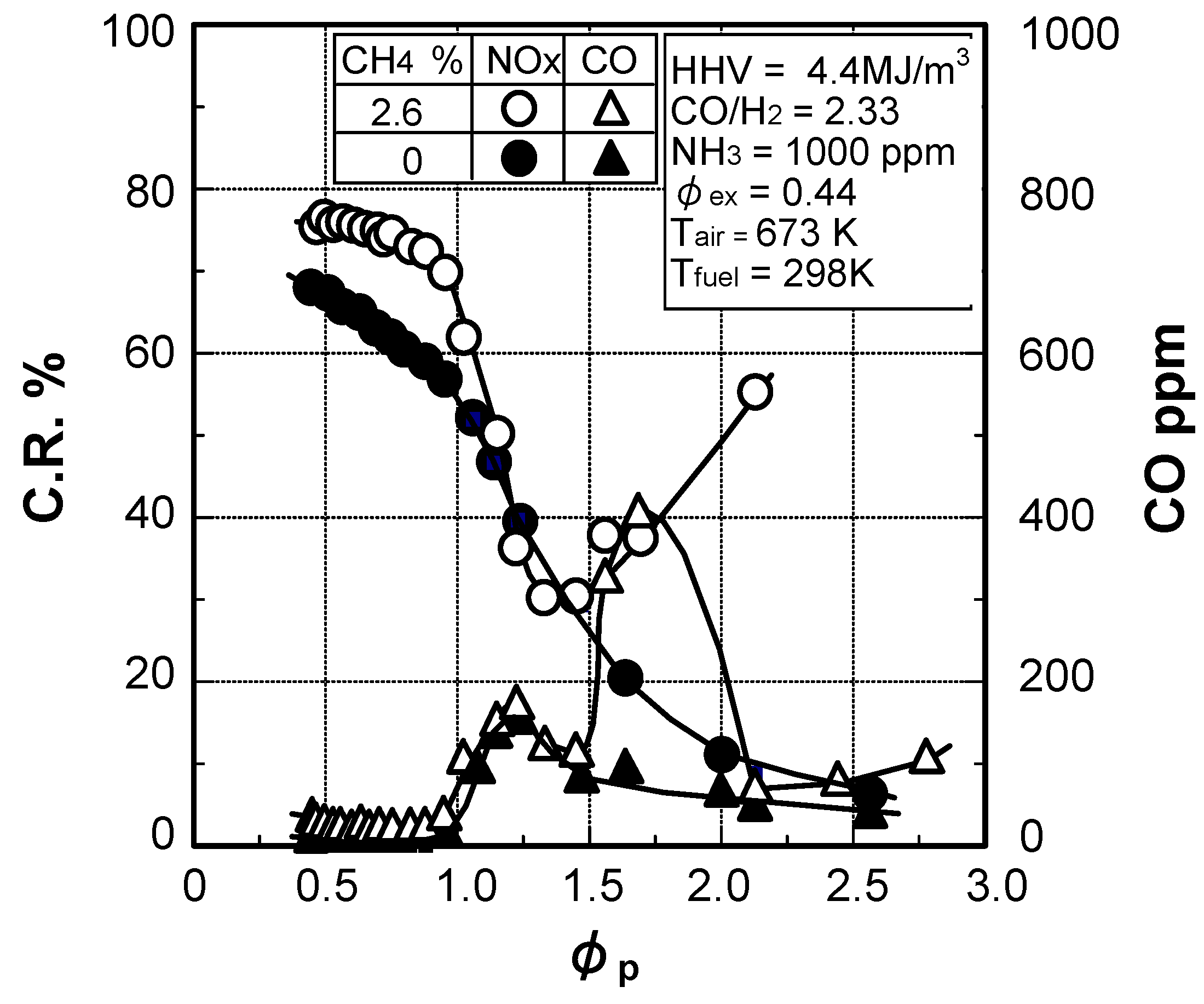
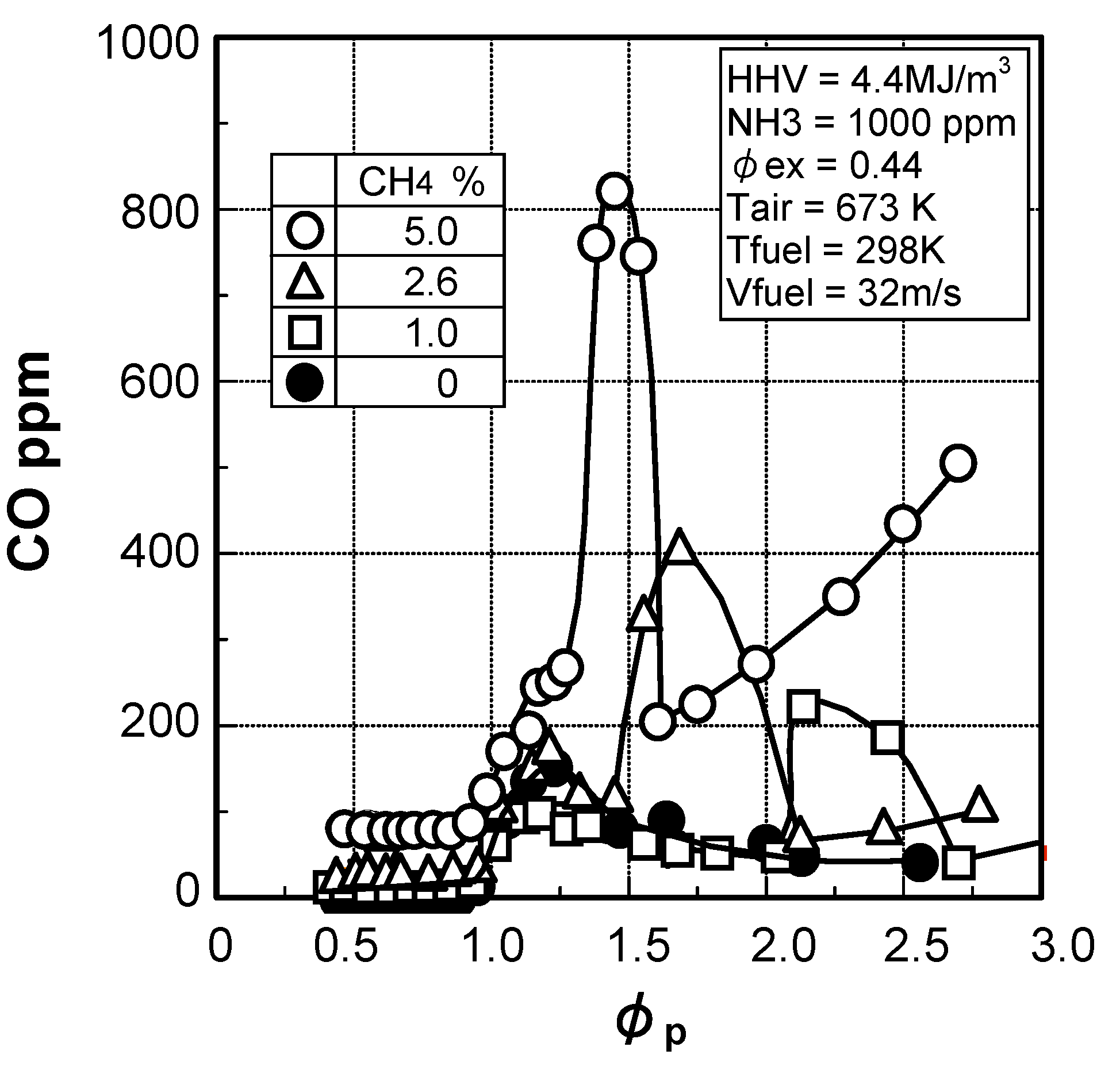
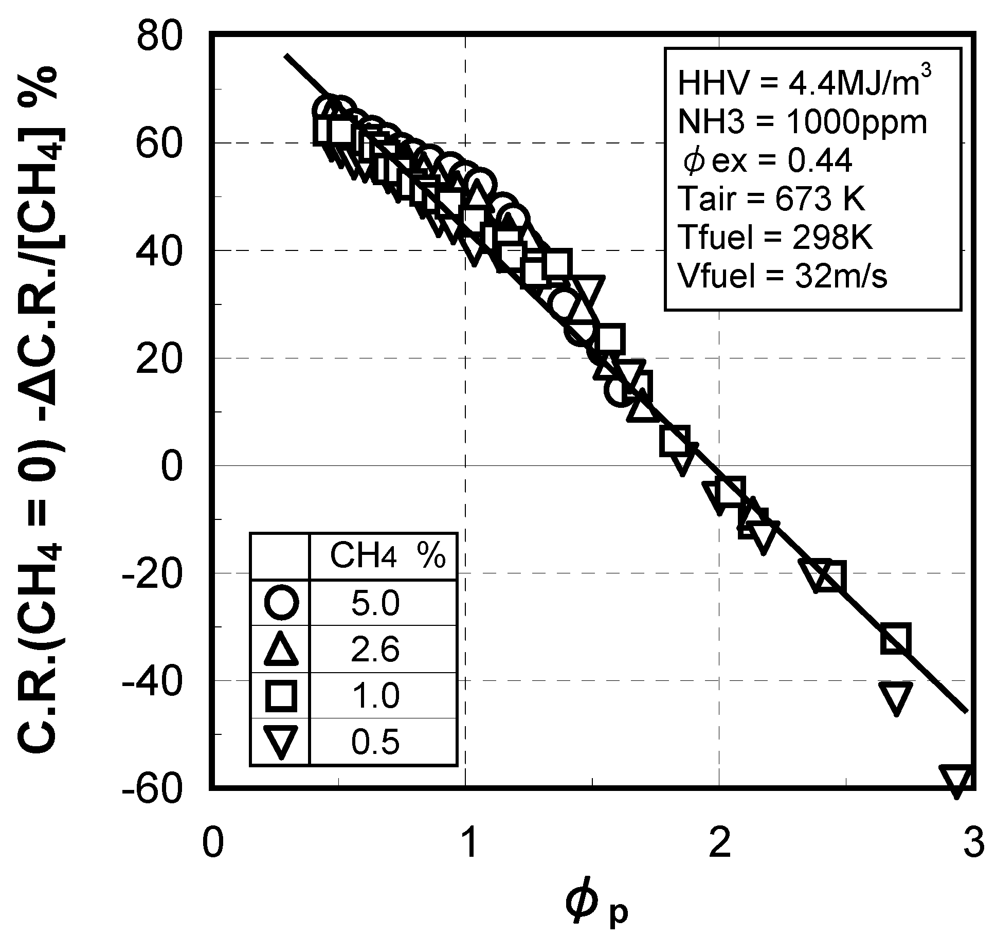
(2) Effect of CH4 concentration in fuel

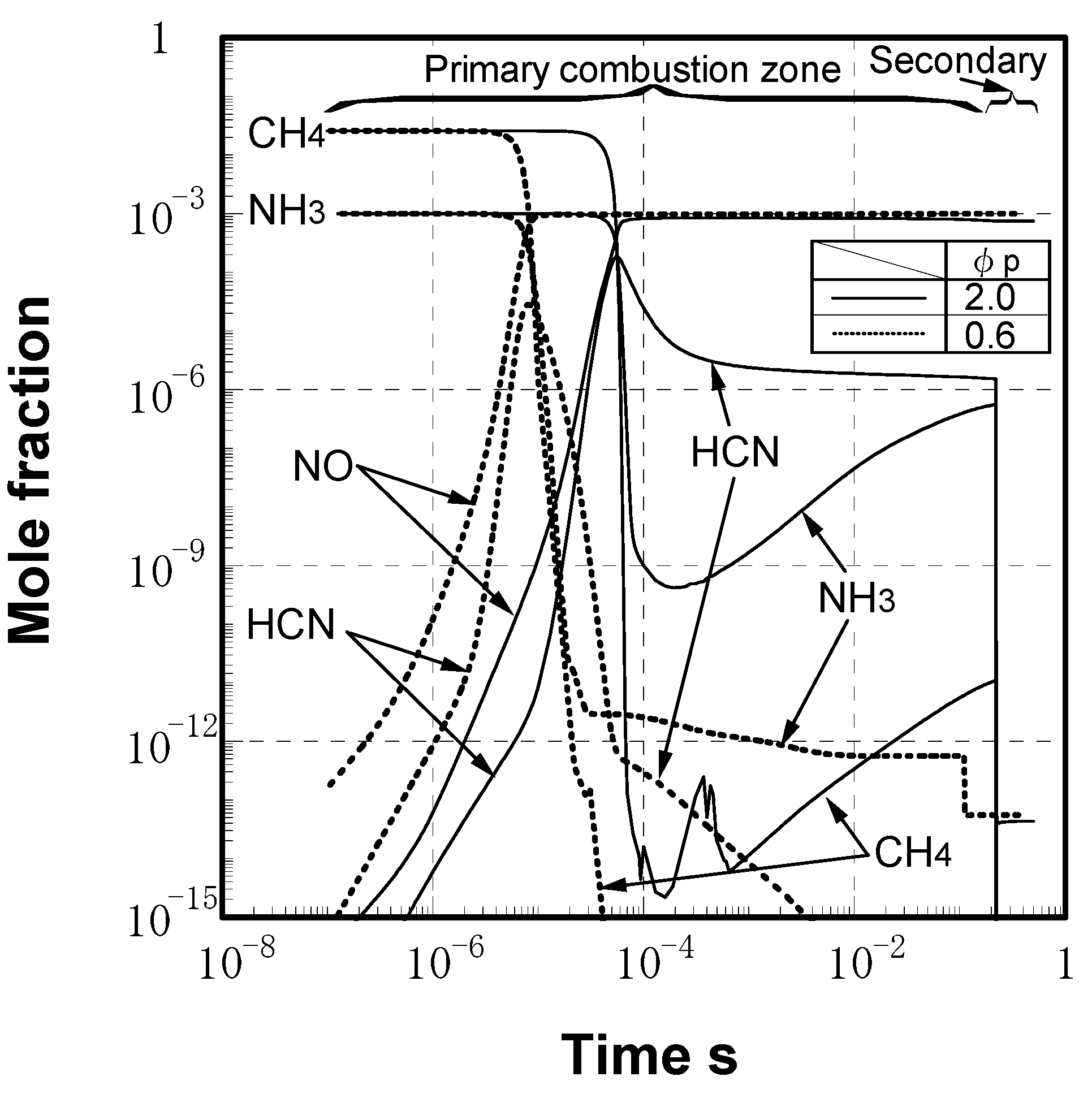
(3) Numerical analysis using an elementary reaction model for gauging the effects of a CH4 constituent on fuel-NOx formation


(4) Prediction methodology of fuel-NOx emissions


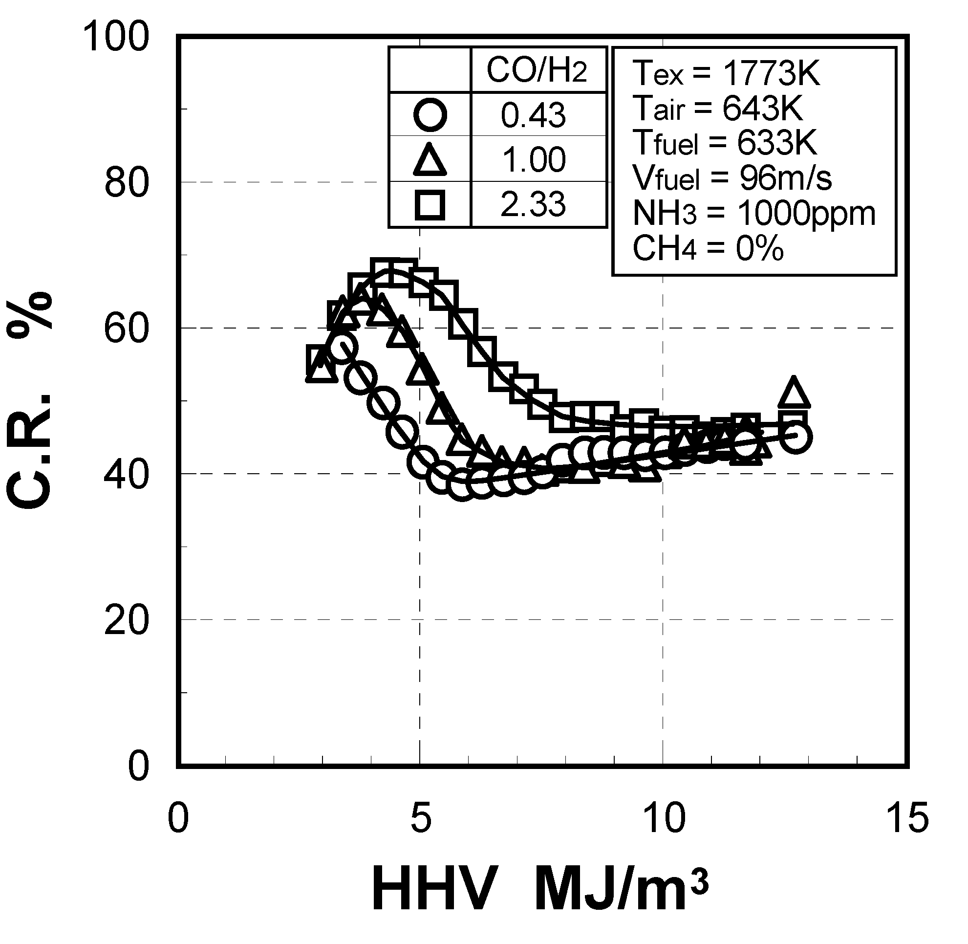
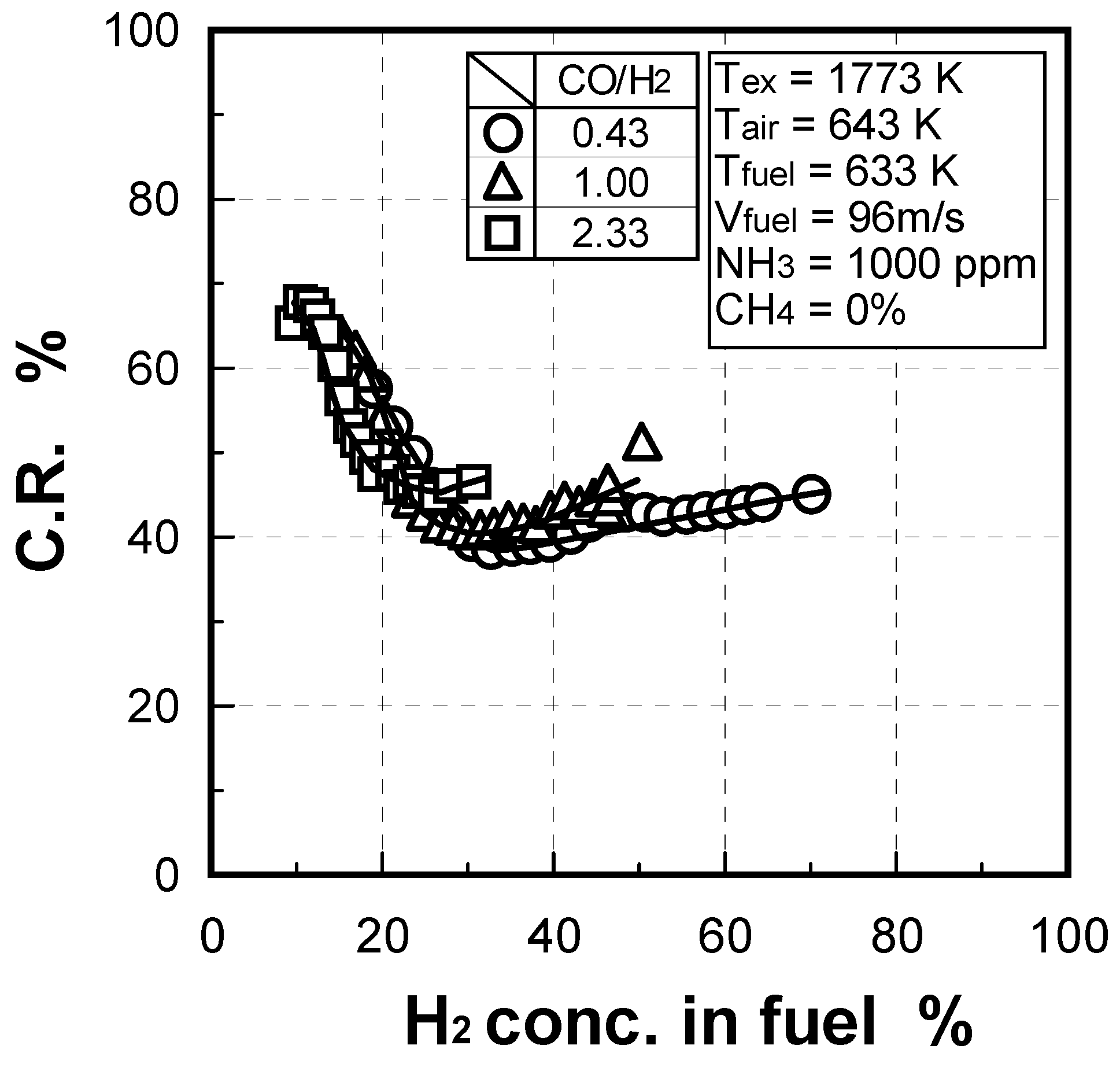
3.1.4. Combustion emission characteristics of medium-Btu fuel
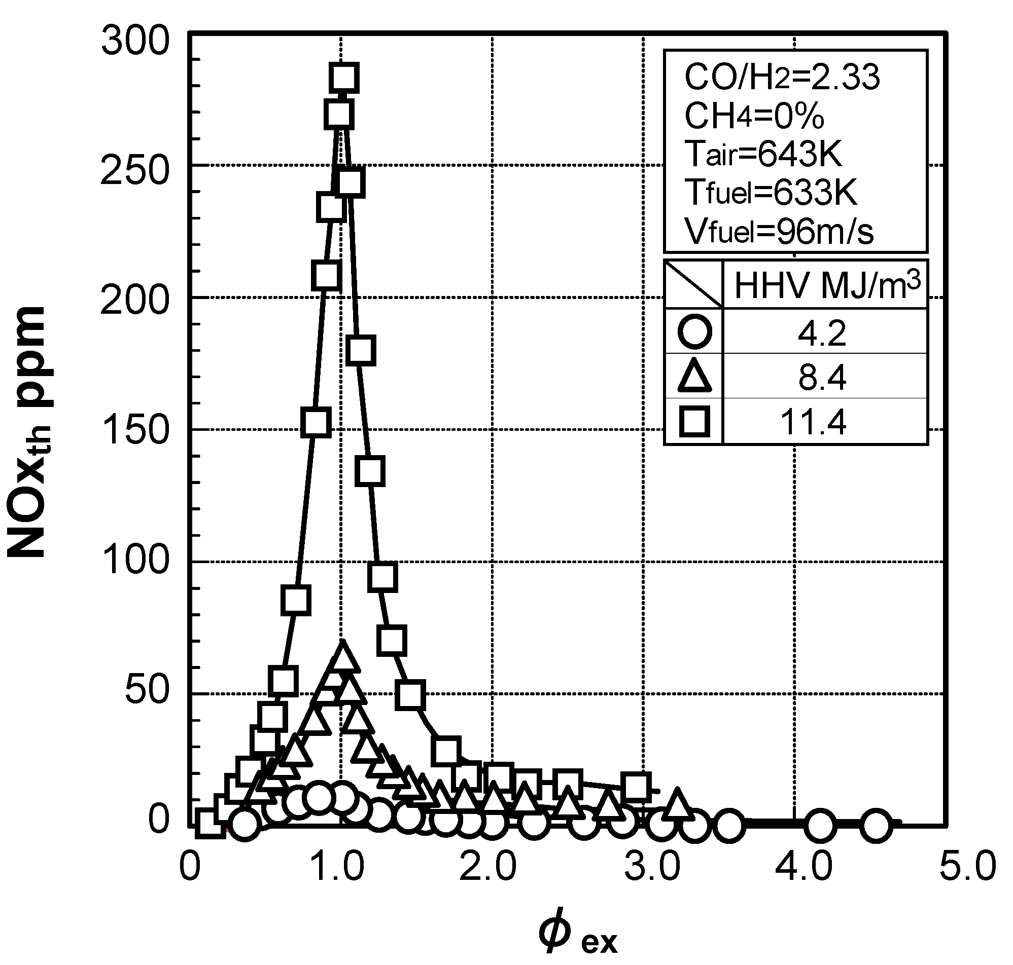
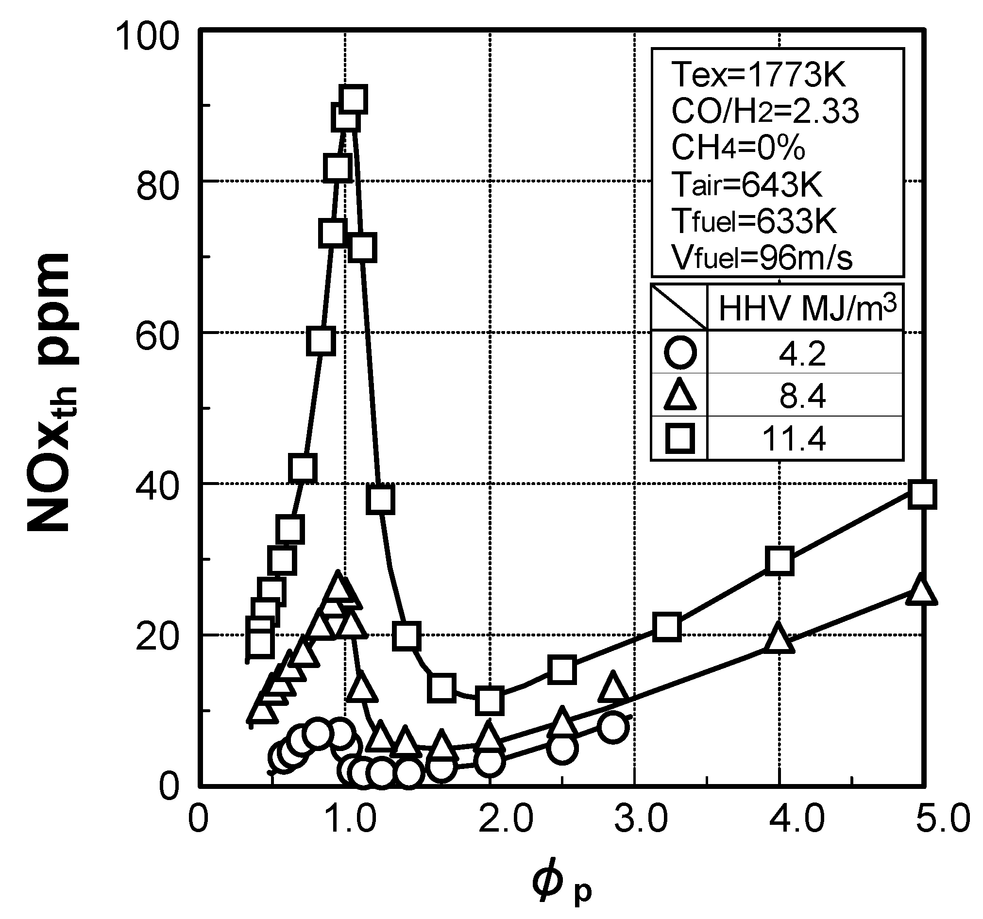
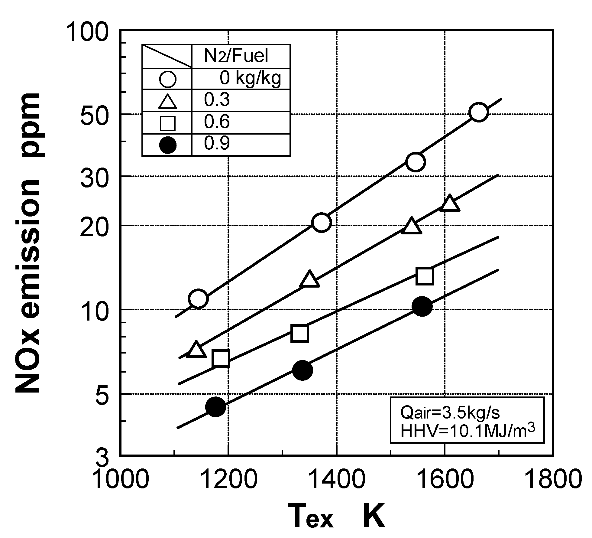
Thermal-NOx emission characteristics


Fuel-NOx emission characteristics

3.2. Non-catalytic reduction of NH3 from gasified fuel
3.2.1 Experimental device and numerical analysis model
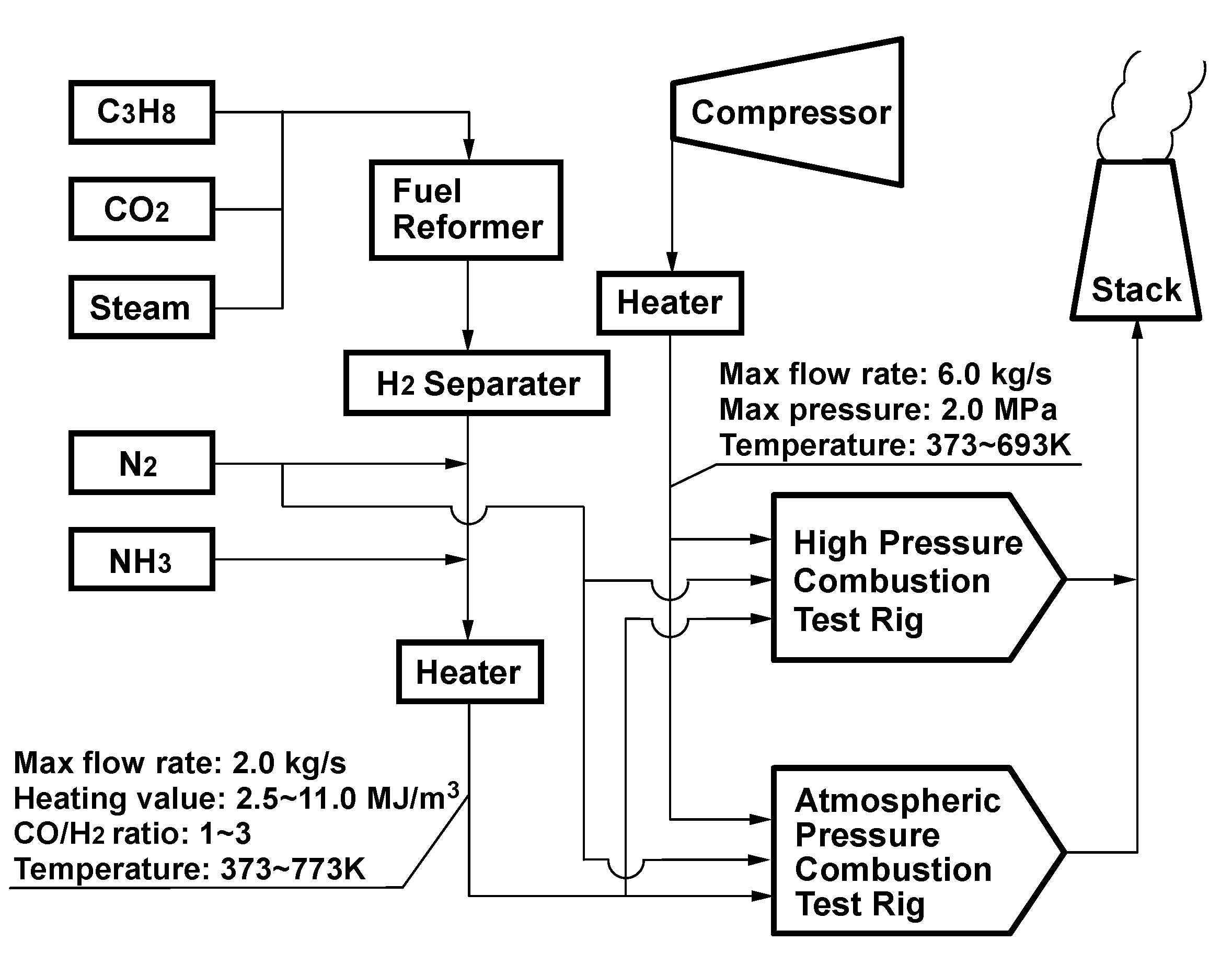
Experimental device and method
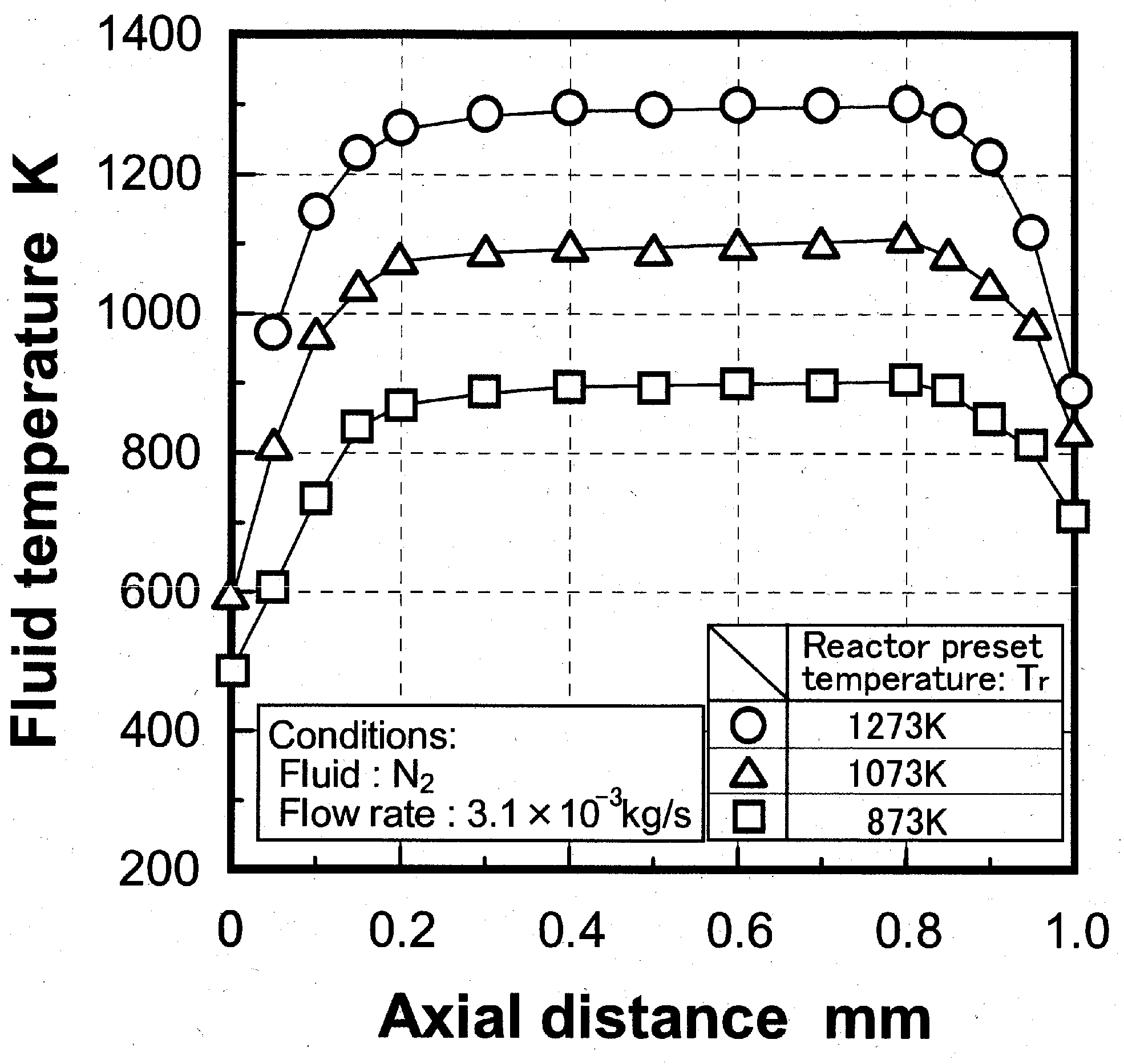
Temperature distribution in reactor
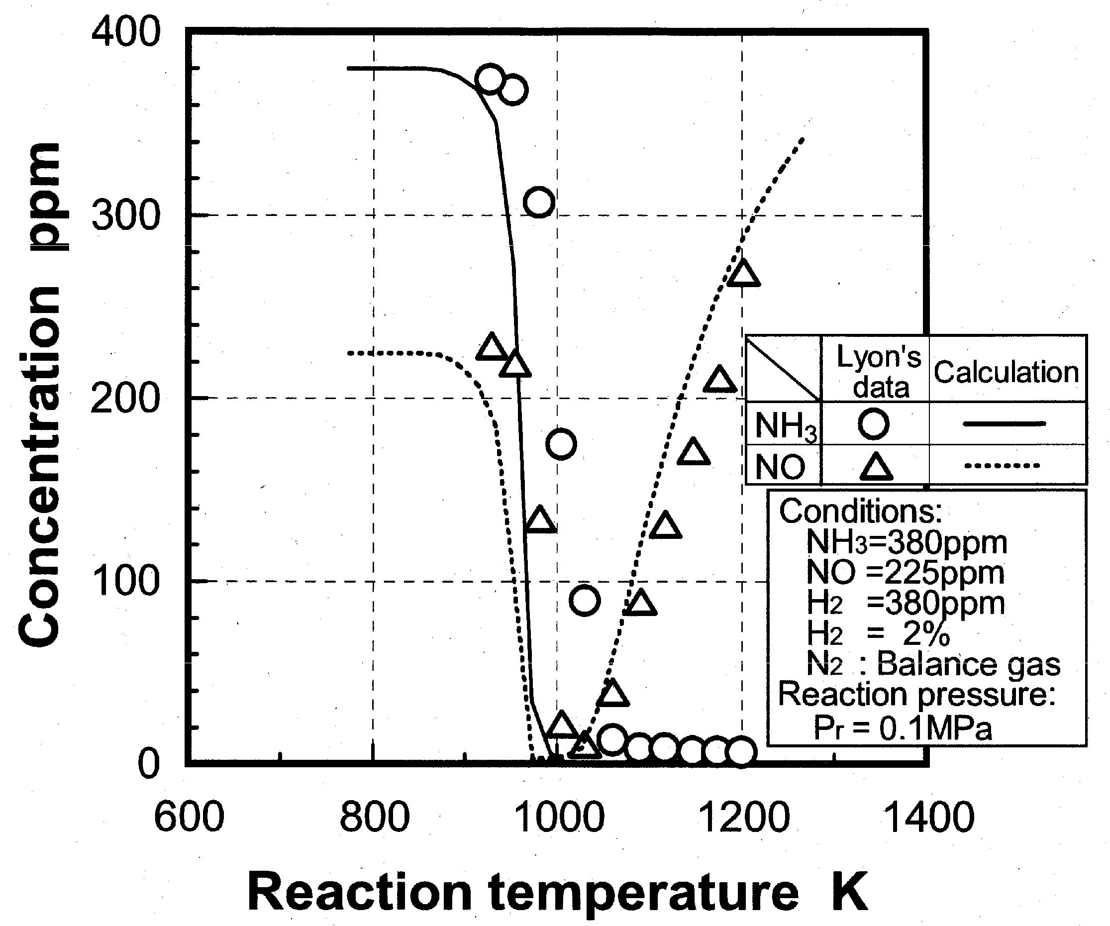
Analysis model and validity of numerical analysis

3.2.2. Influence of various factors on ammonia removal characteristics
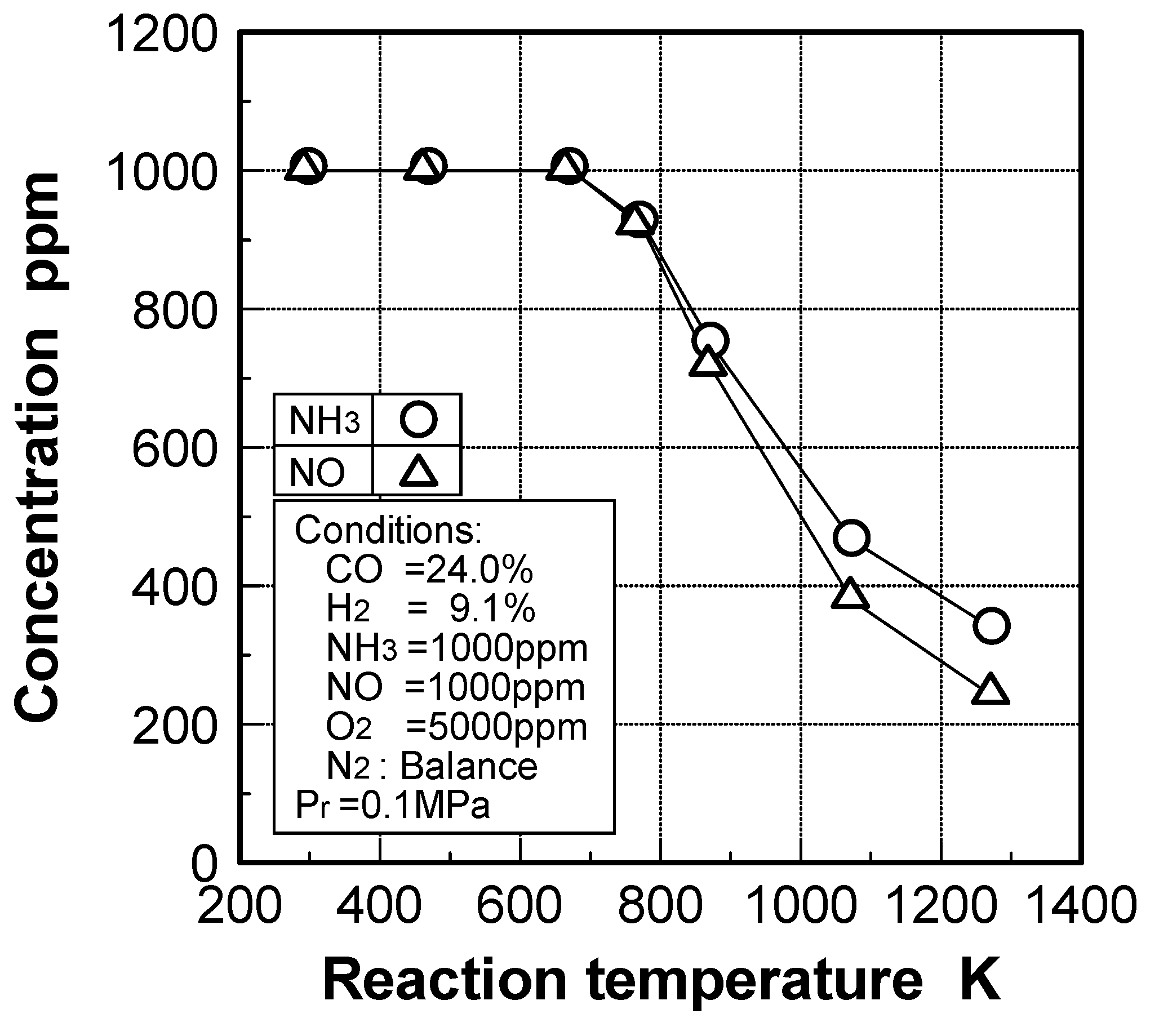
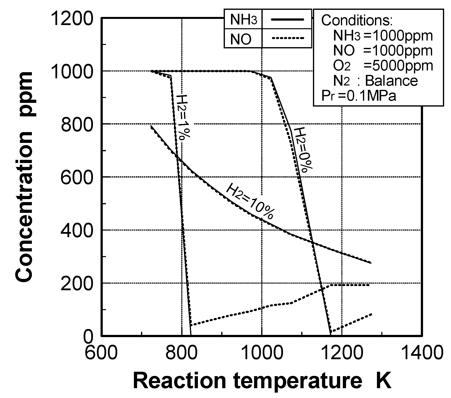
Effects of reaction temperature

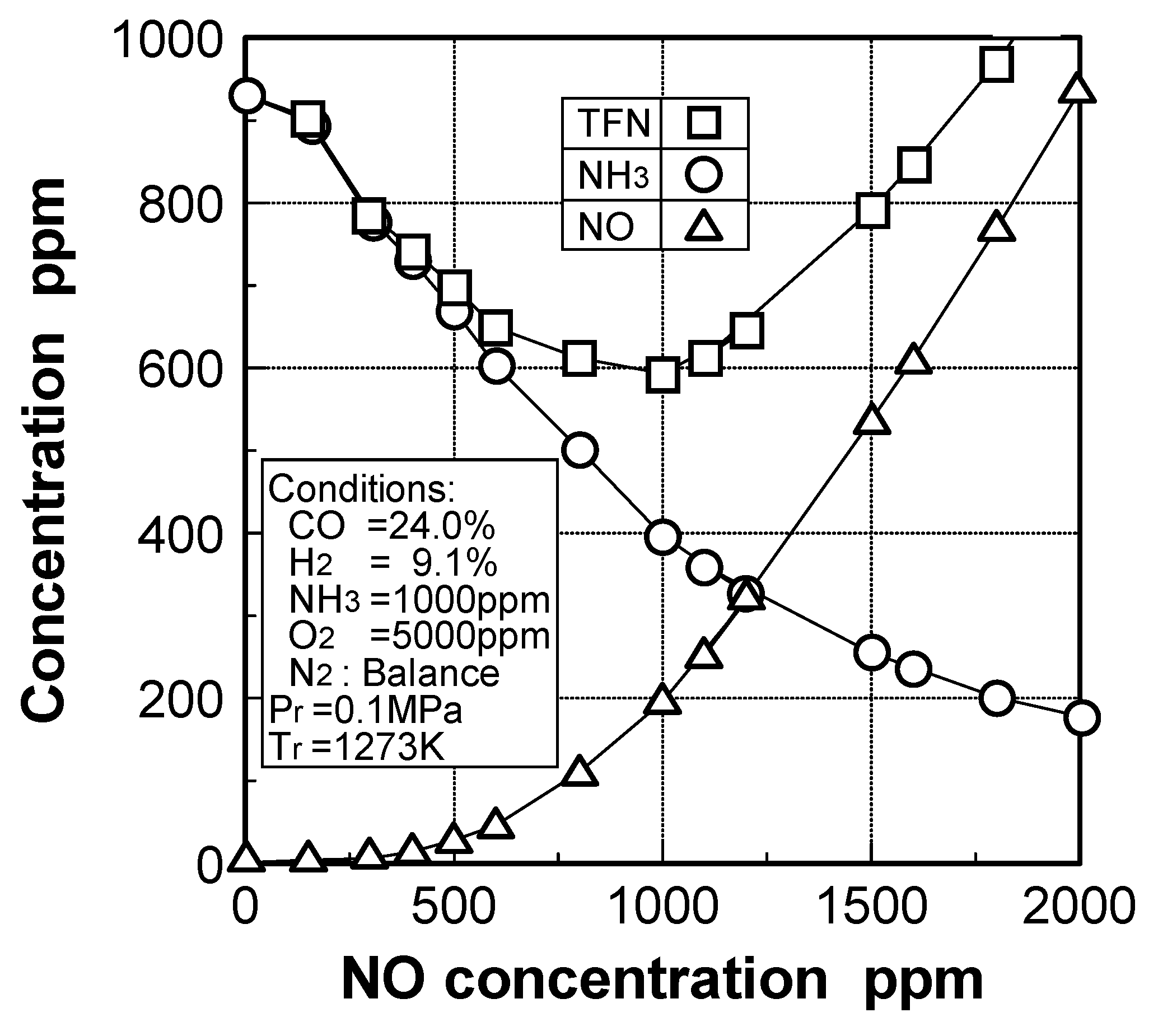
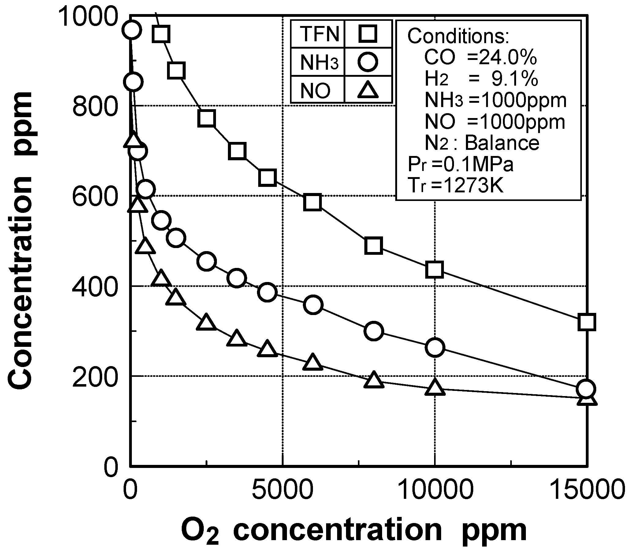
Effects of adding O2 and NO

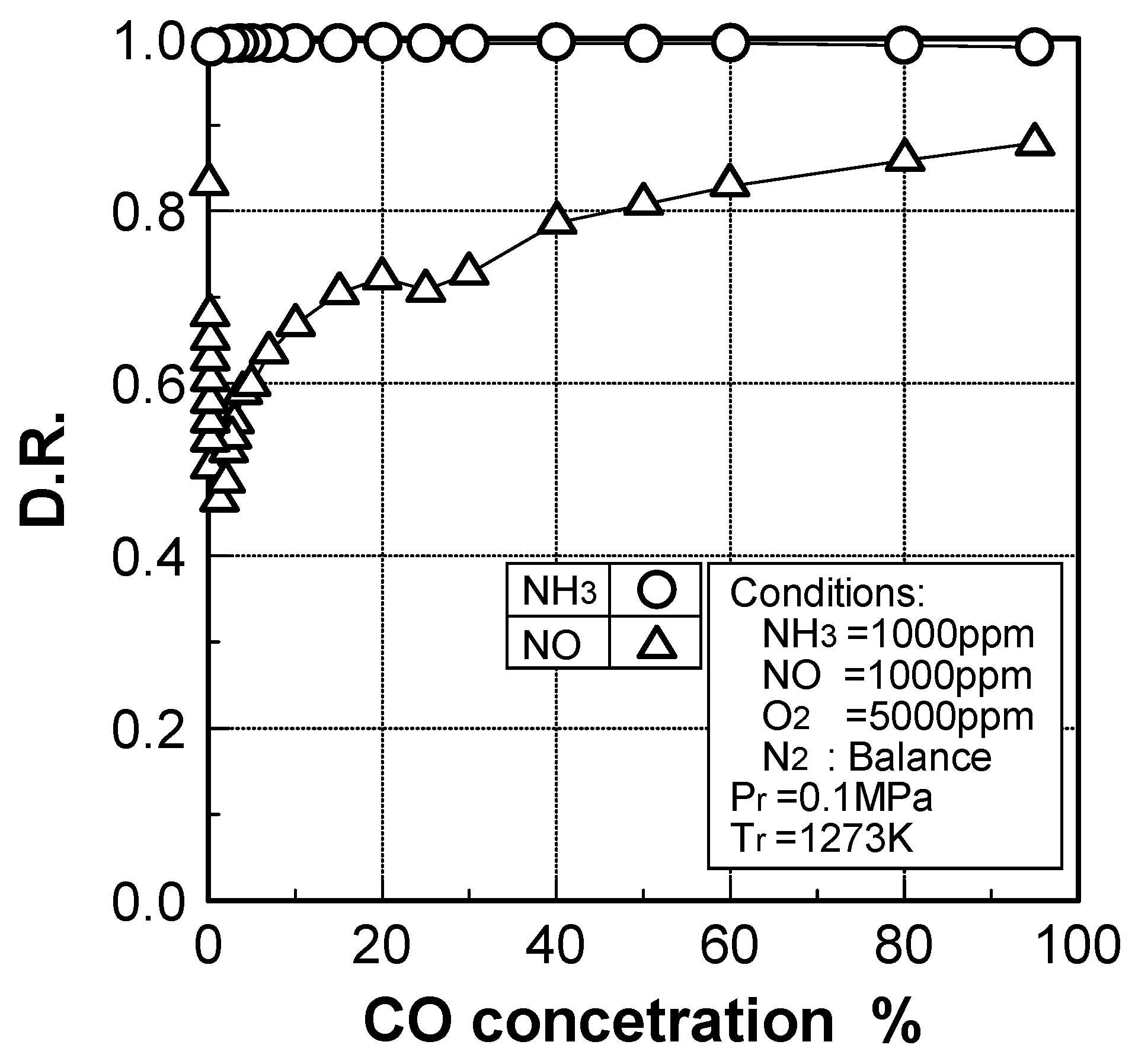
Effects of combustible components
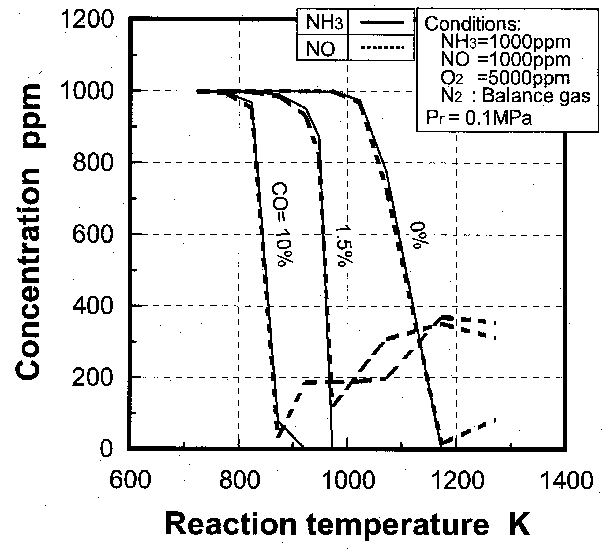
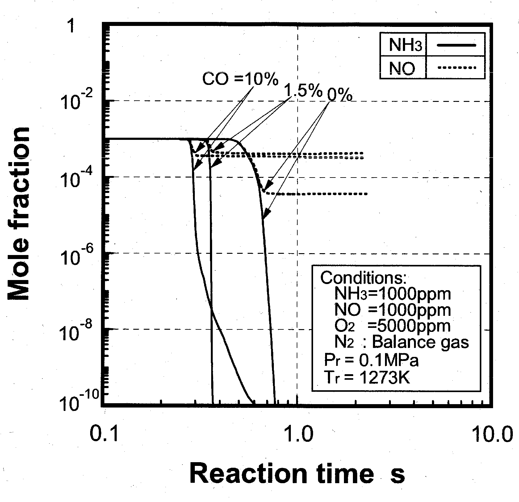
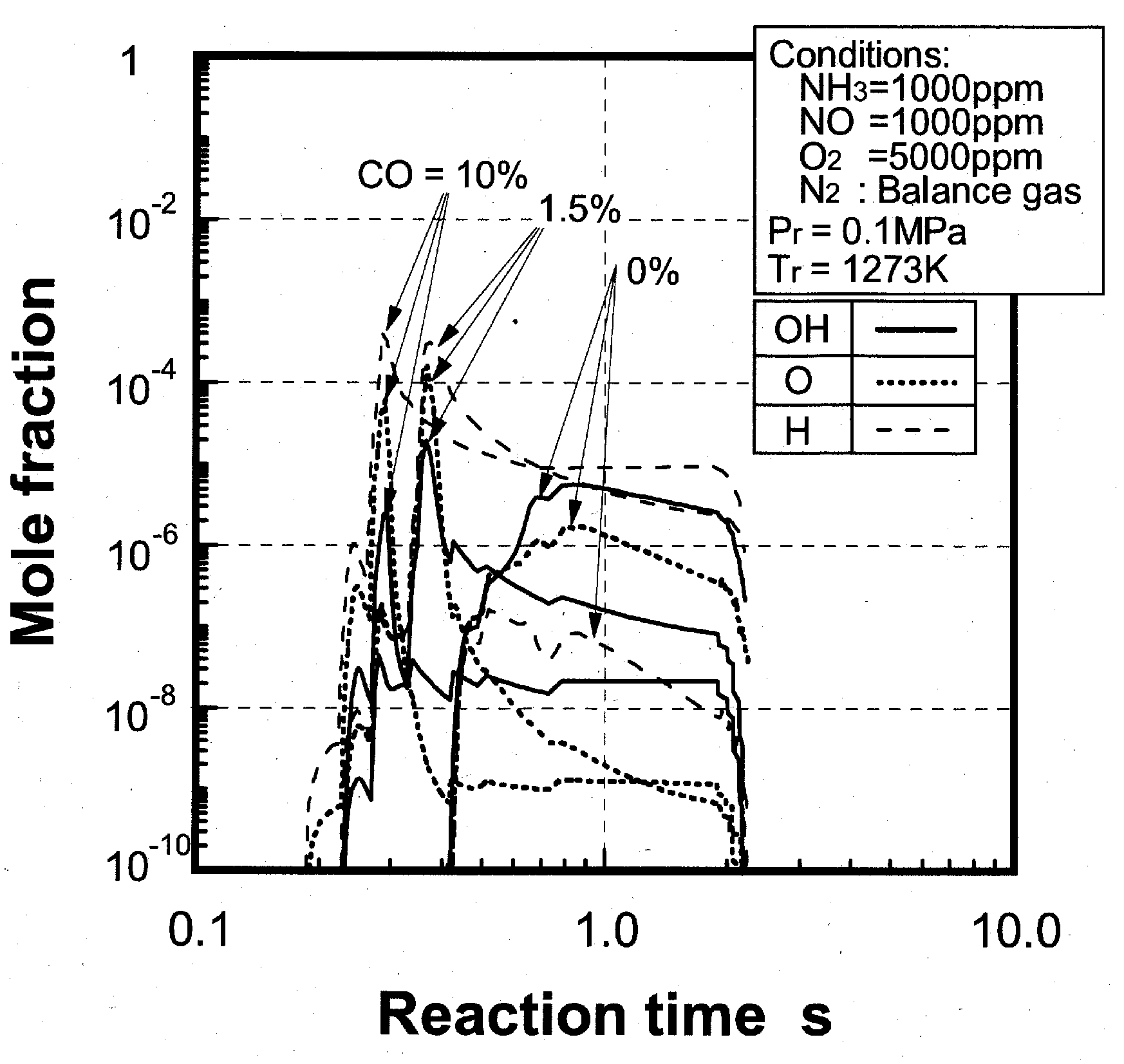
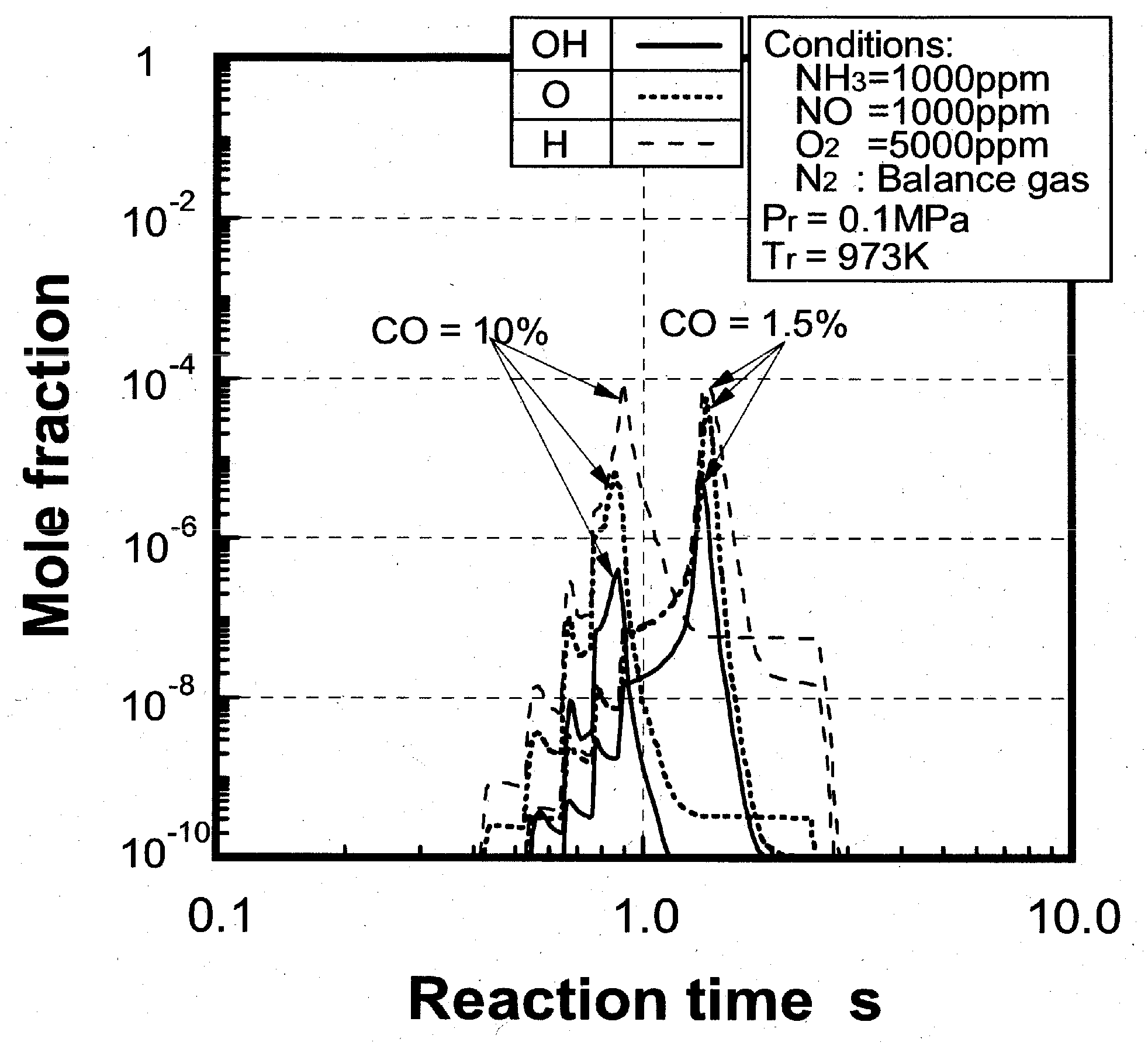
(1) Effects of CO constituent


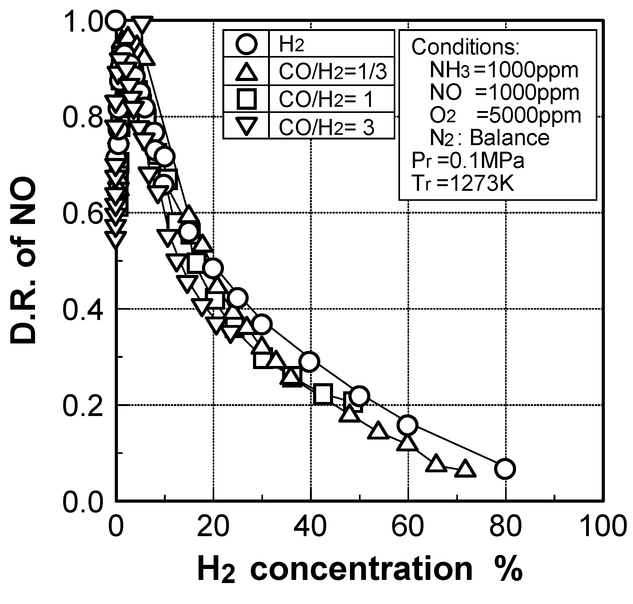
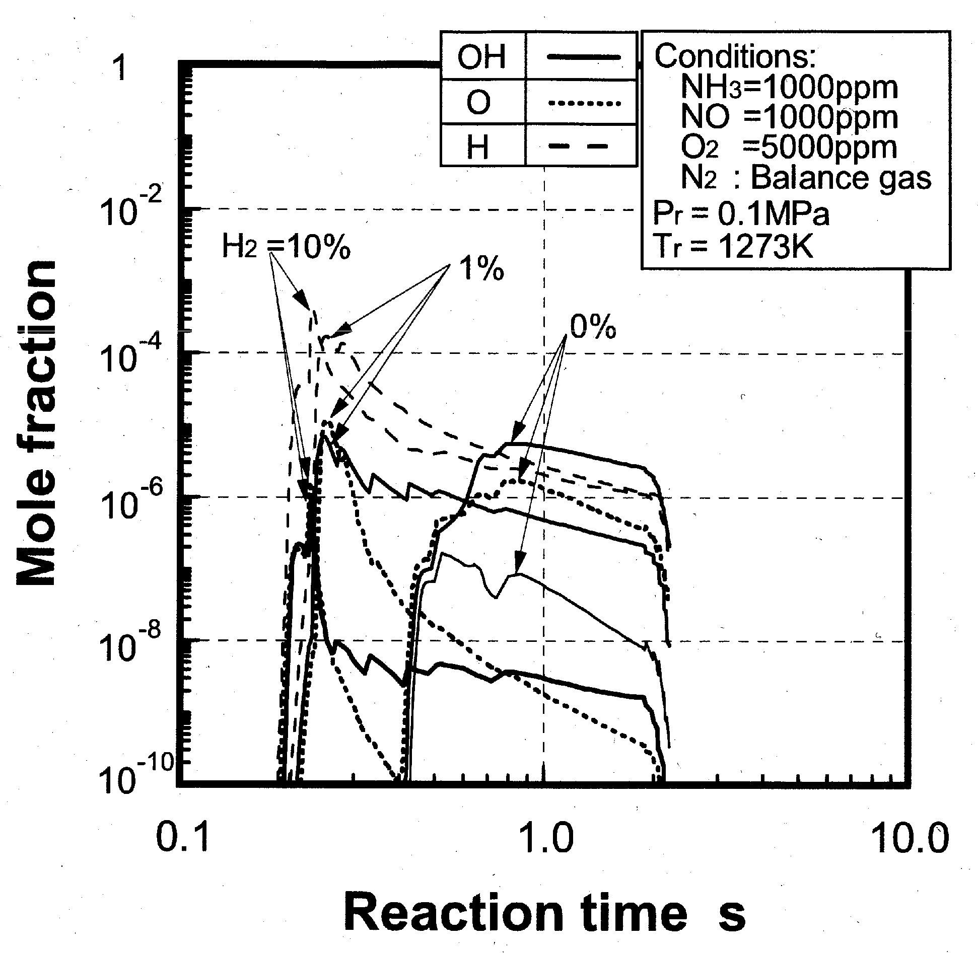
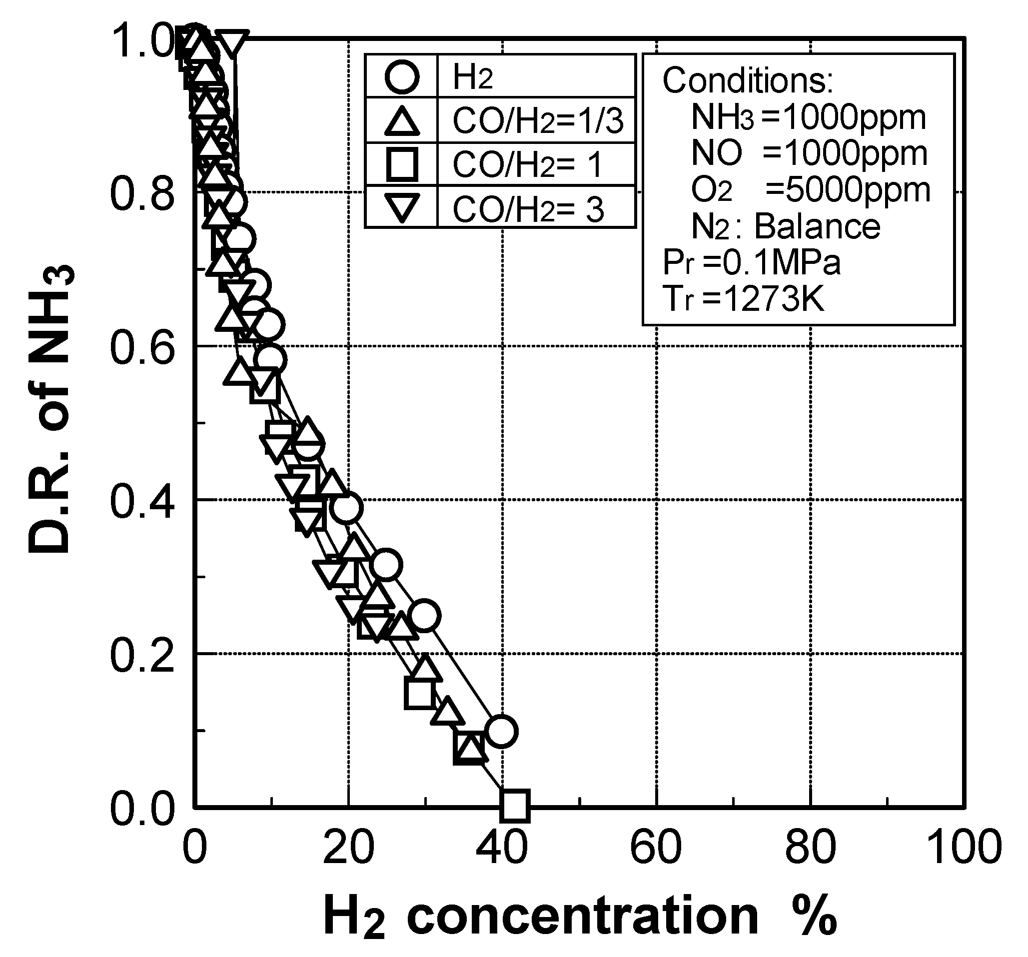
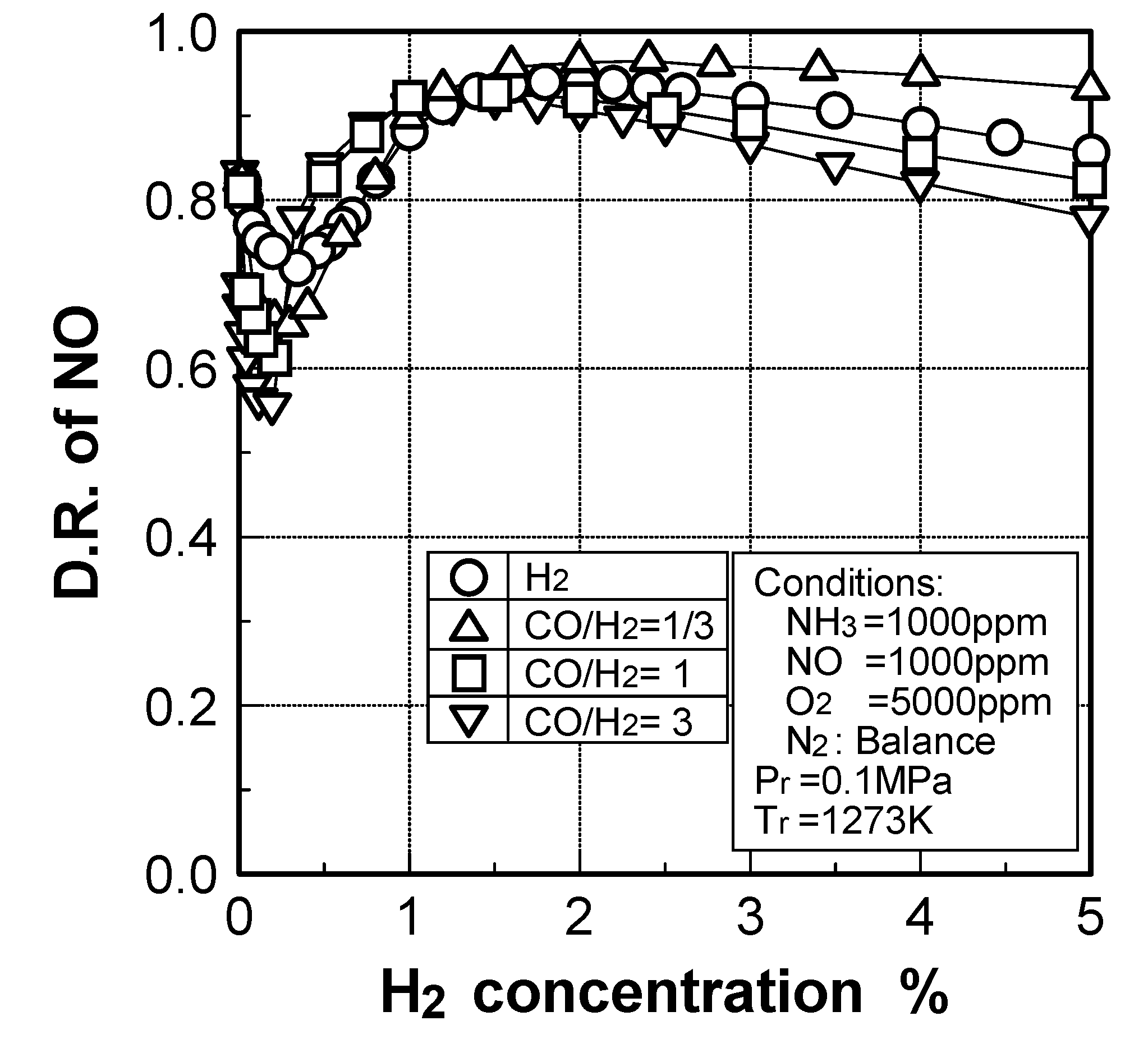
(2) Effects of H2 constituent


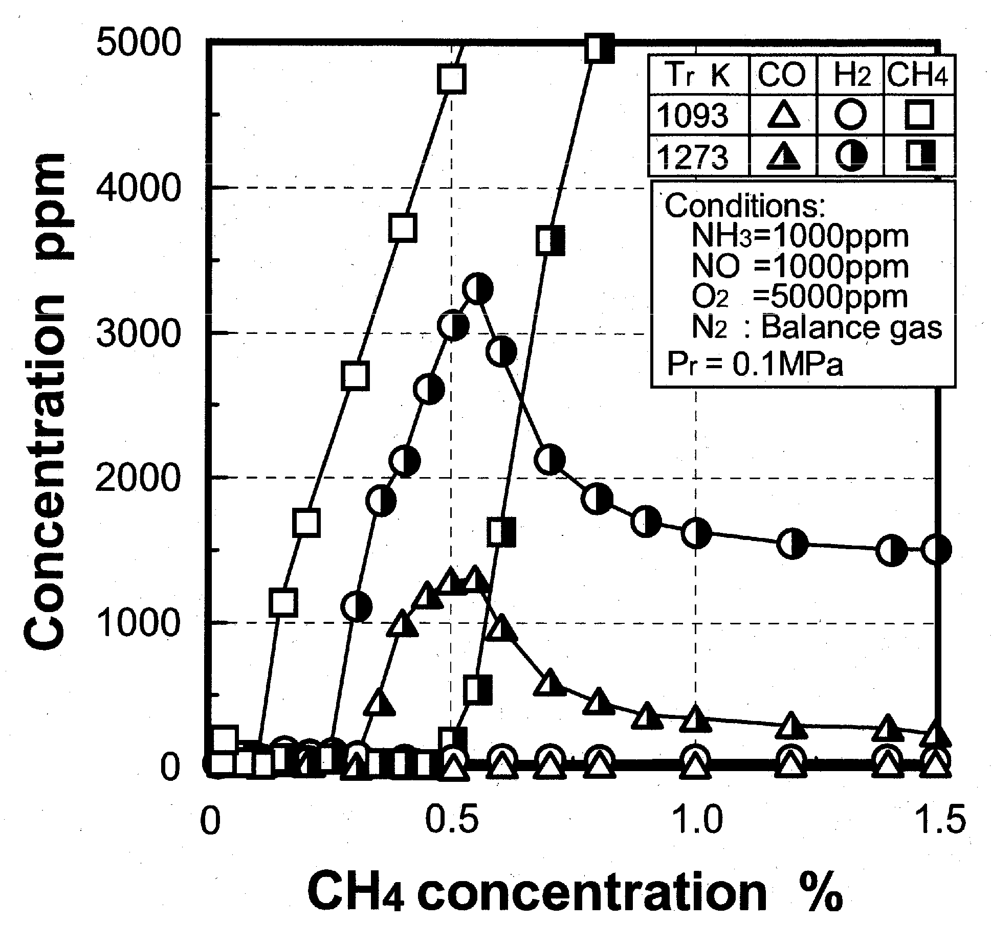
(3) Effects of CH4 constituent
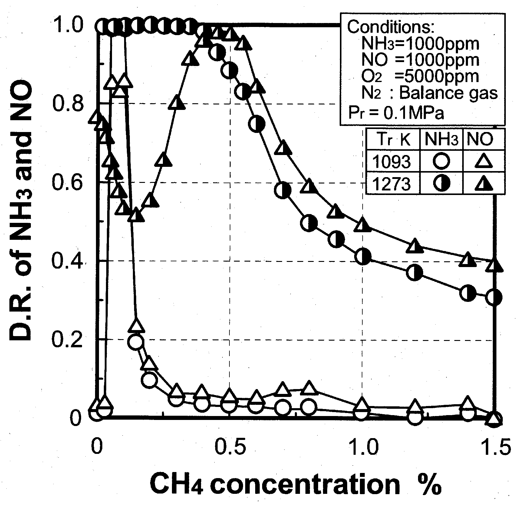

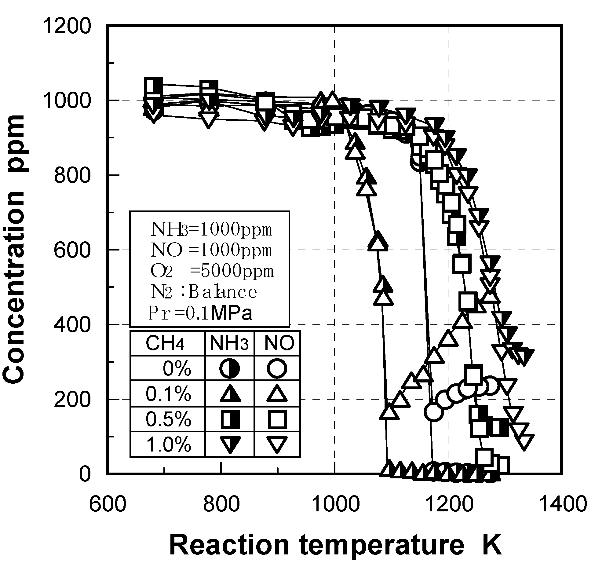
3.2.3. Scope of application
4. Test Facility and Method for Demonstration and Combustion Characteristic-Evaluation of Gasified Fueled Combustors
4.1. Test facilities

4.2. Measurement system

5. Combustor for Air-Blown Gasification System with Hot/Dry Type Synthetic Gas Cleanup
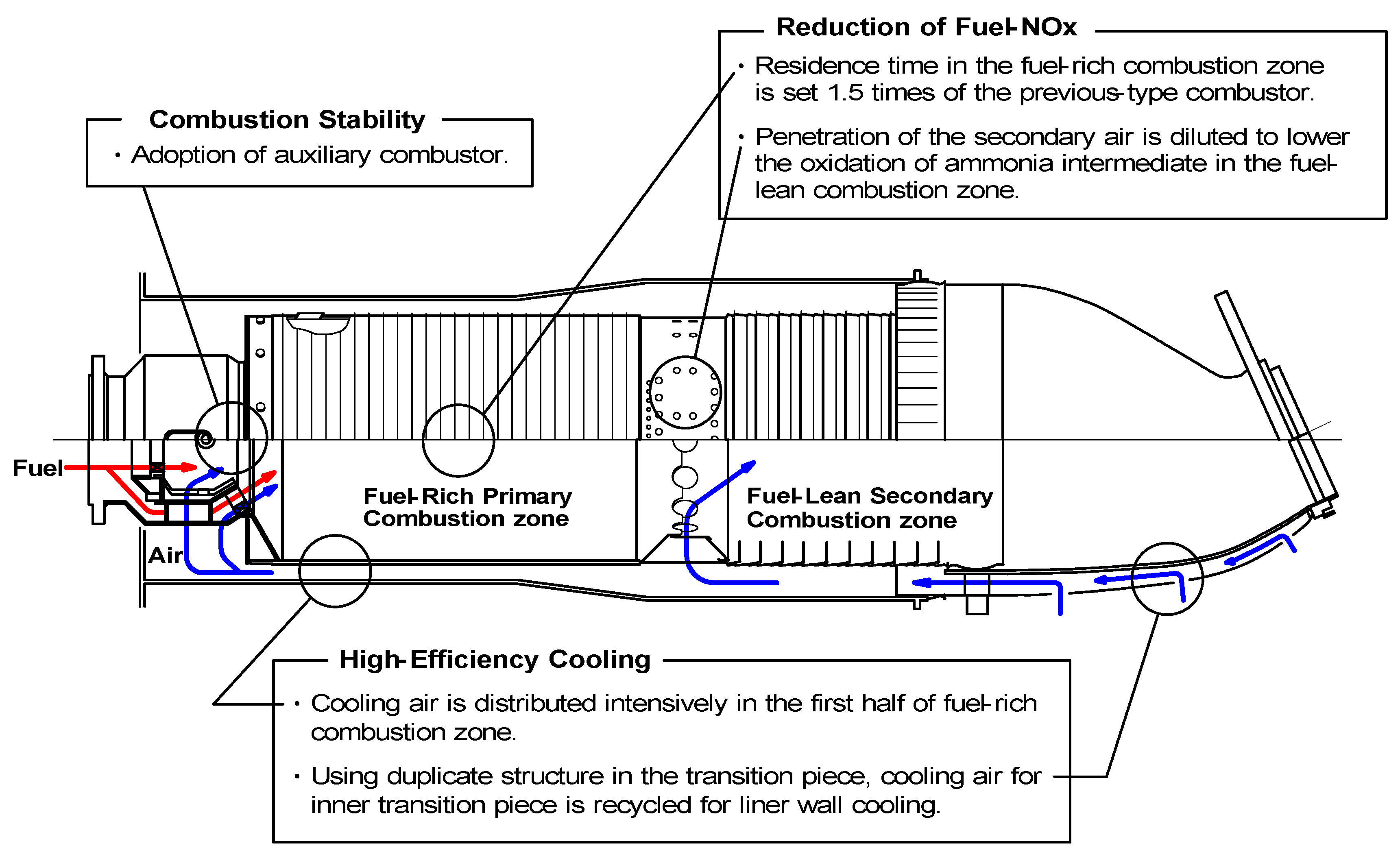
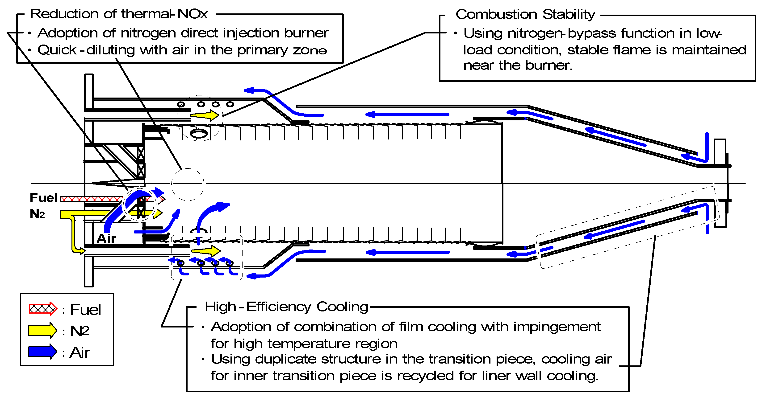
5.1. Design concept of combustor

- (1)
- Combustion stability. It is necessary to stabilize the flame of low-calorific fuel.
- (2)
- Low NOx emission technology to restrain the production of fuel-NOx from NH3 in the fuel.
- (3)
- Cooling structure to cool the combustor wall efficiently with less amount of air.

5.1.1. Assurance of flame stabilization
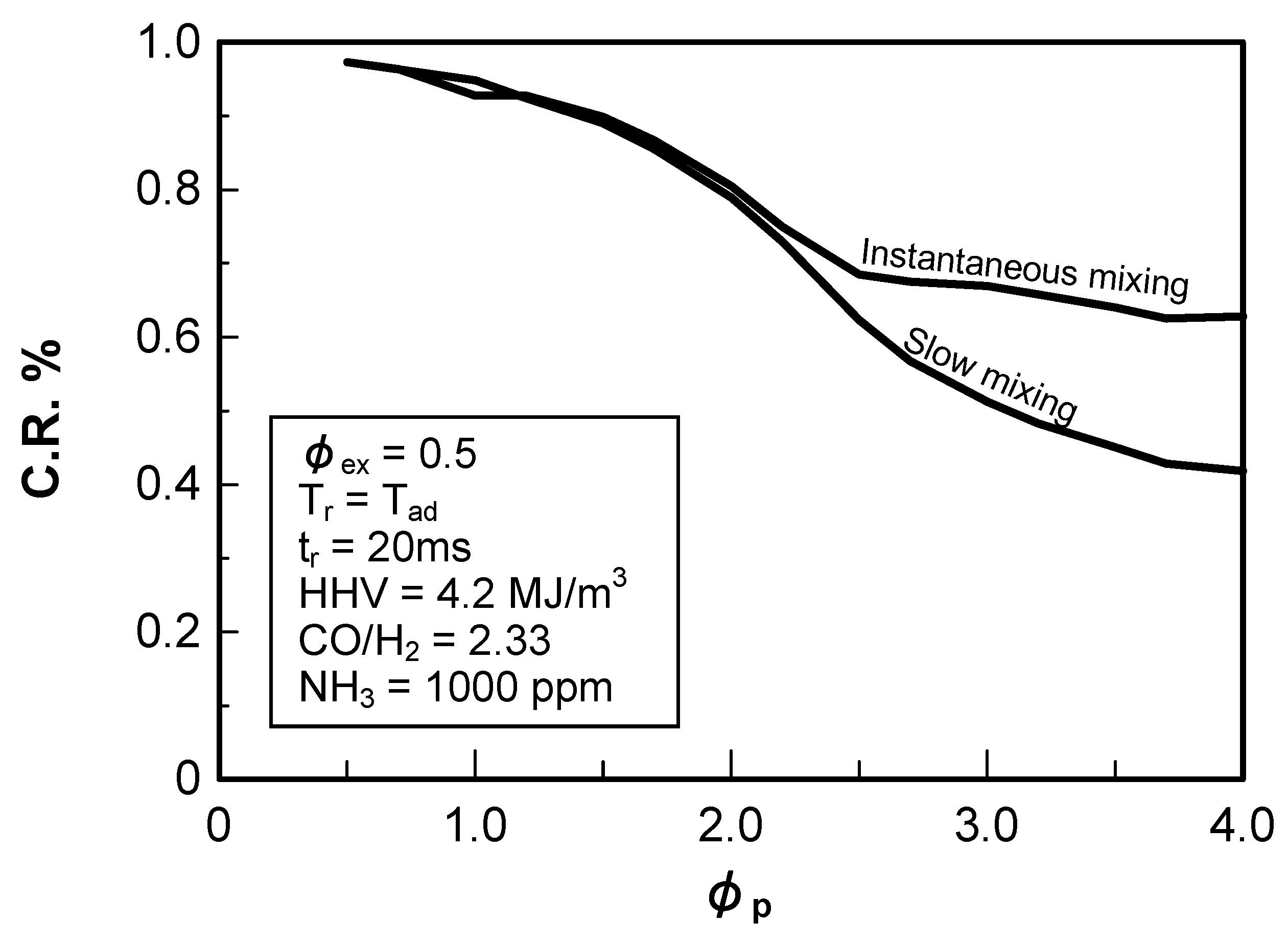
5.1.2. Fuel-NOx reduction
(1) Air to fuel ratio in primary combustion zone
(2) Introduction method of secondary air

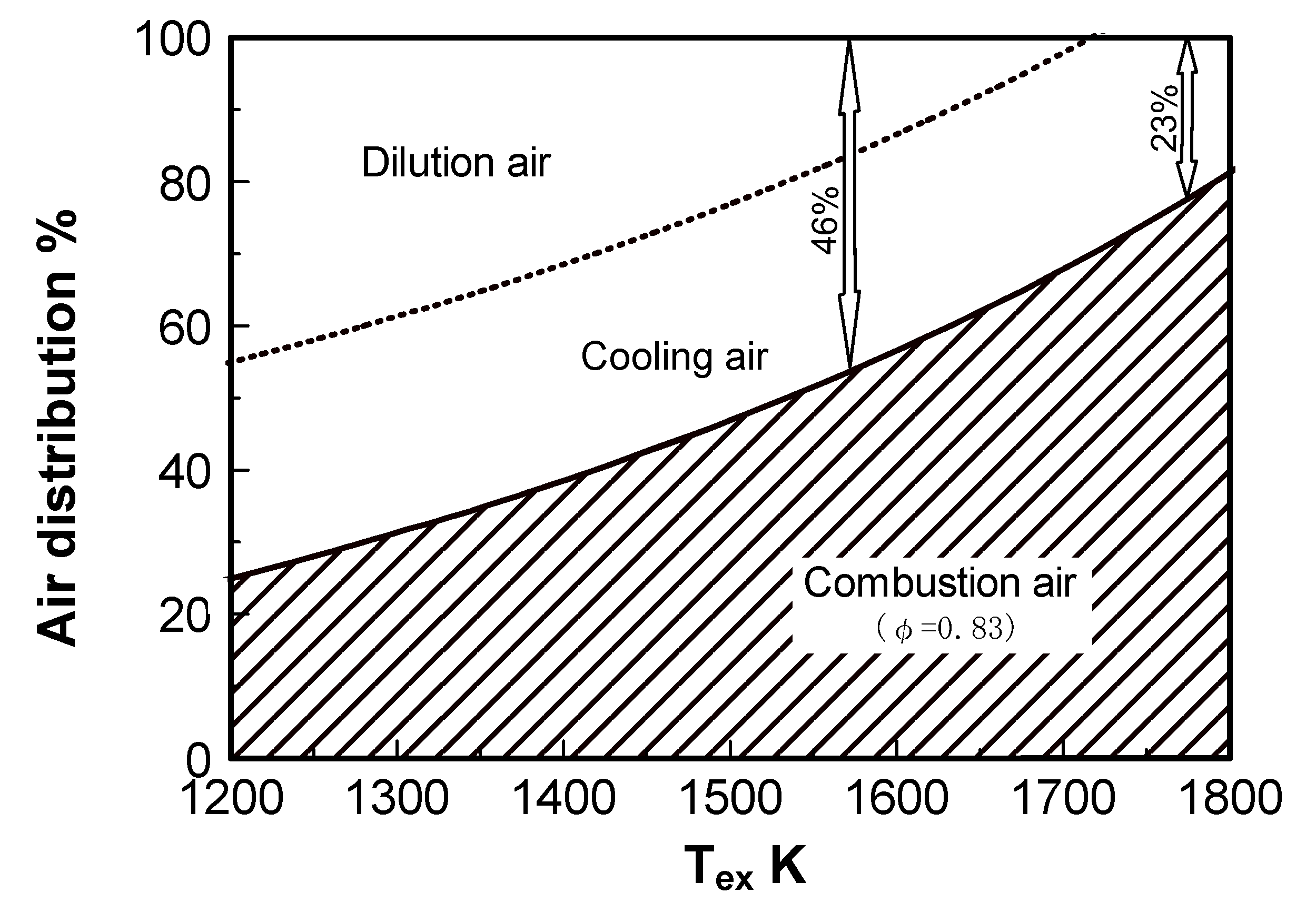
5.1.3. Cooling of combustor liner wall
| Tair | 700 K |
| Tfuel | 633 K |
| Tex | 1773 K |
| Ur | 16 m/s |
| P | 1.4 MPa |
| φex | 0.62 |
| Combustion Intensity | 2.0 × 10² W/(m3 ·Pa) |
5.2. Test results
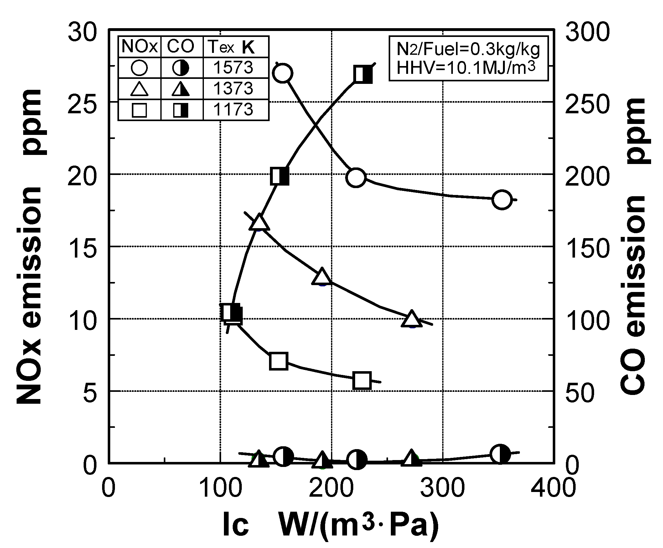
5.2.1. Combustion emission characteristics
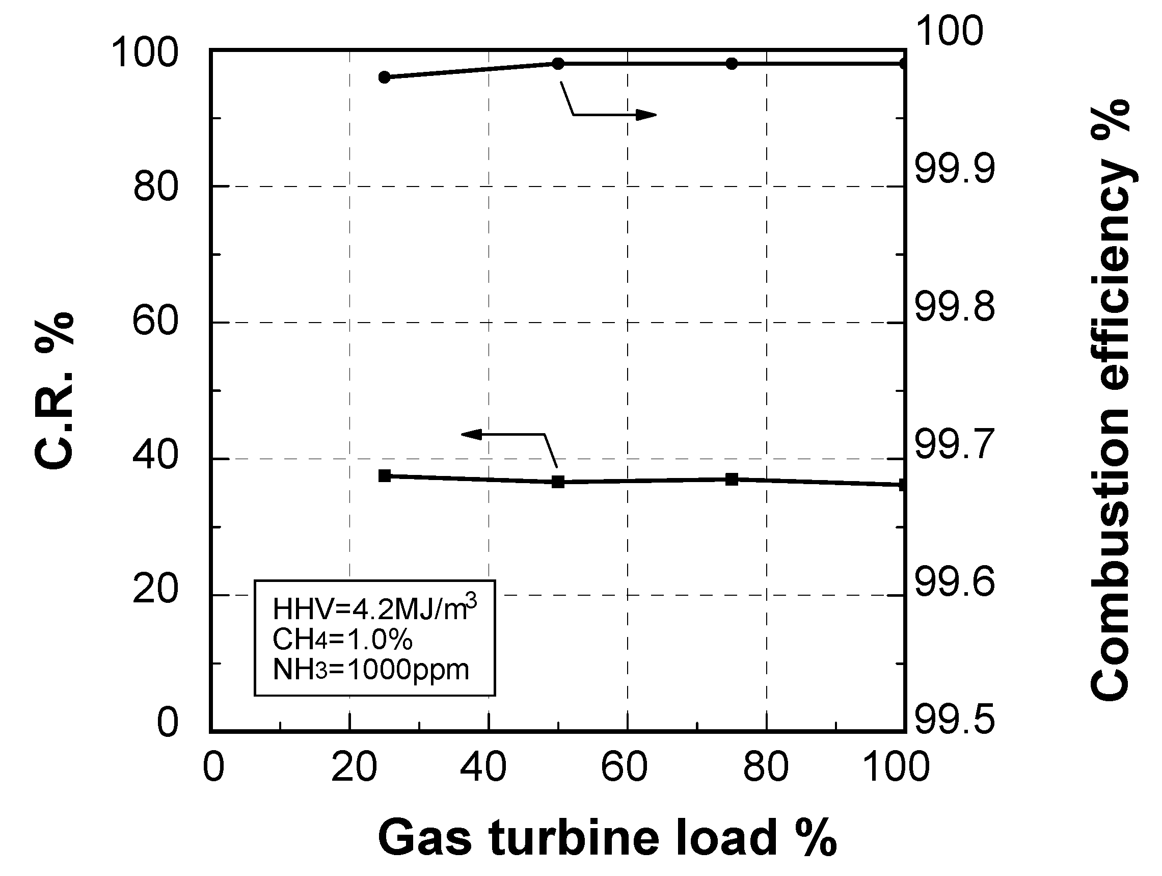
Emission characteristics in gas turbine operations
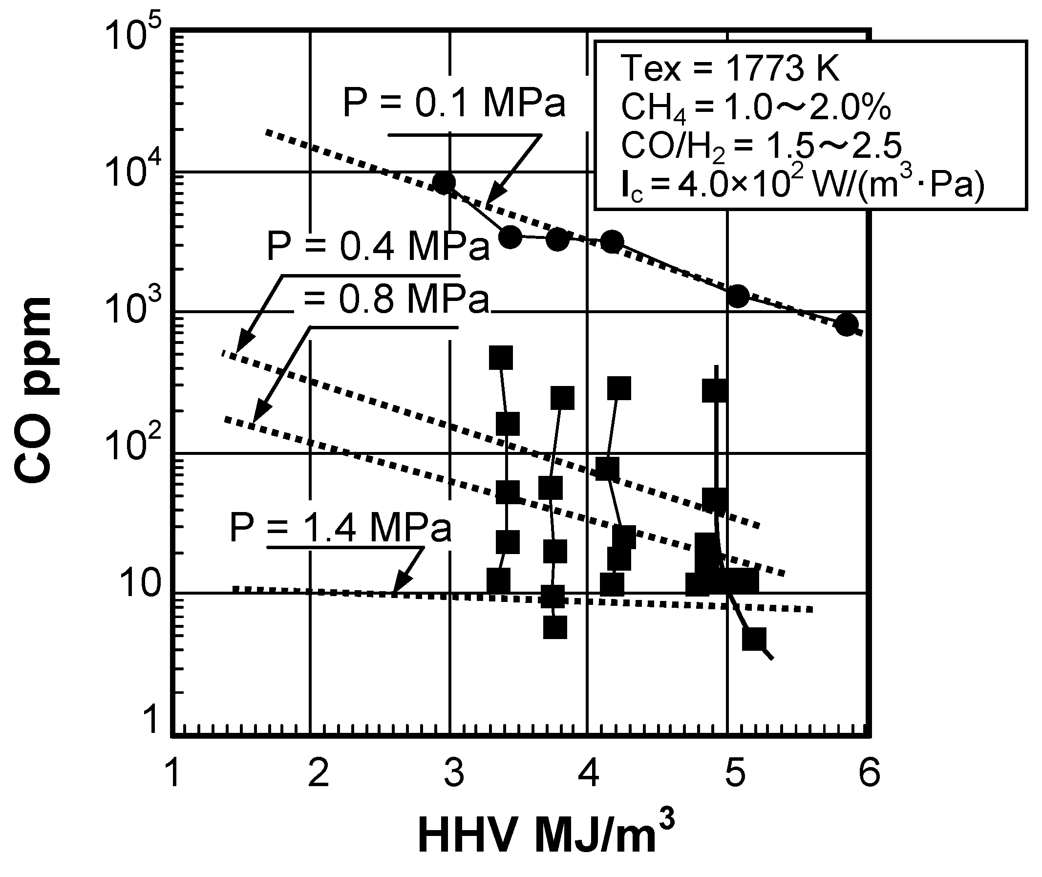
Effect of fuel calorific value on CO emission characteristics

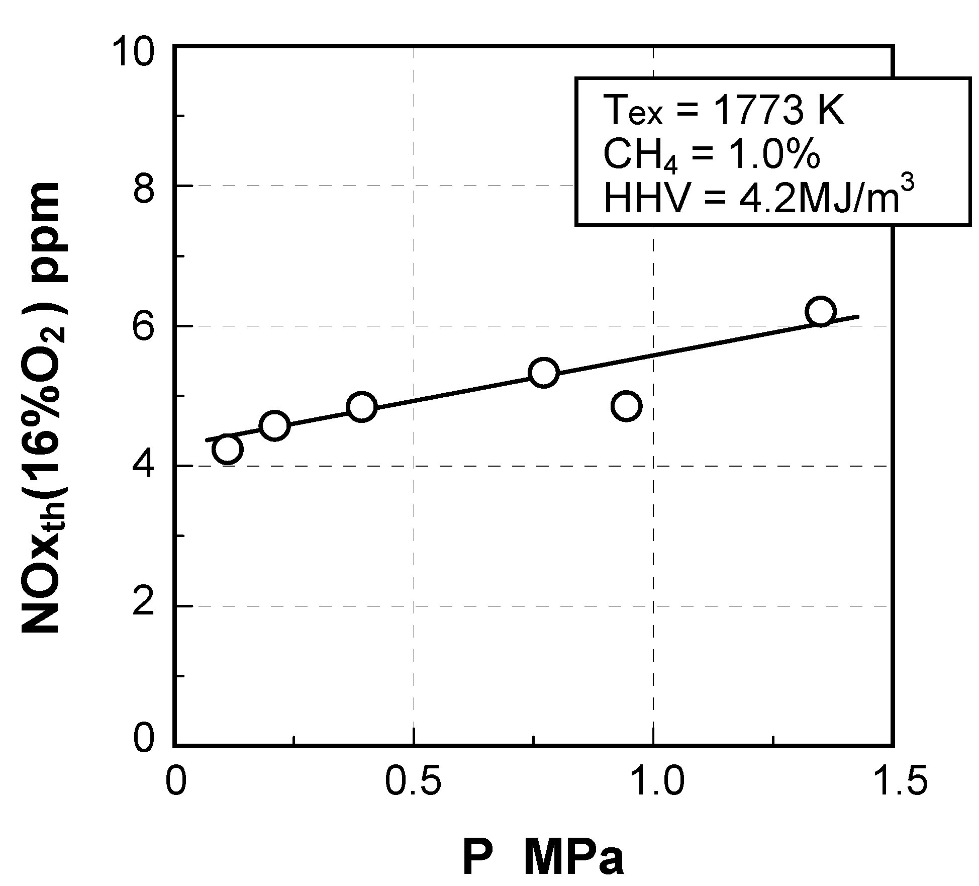
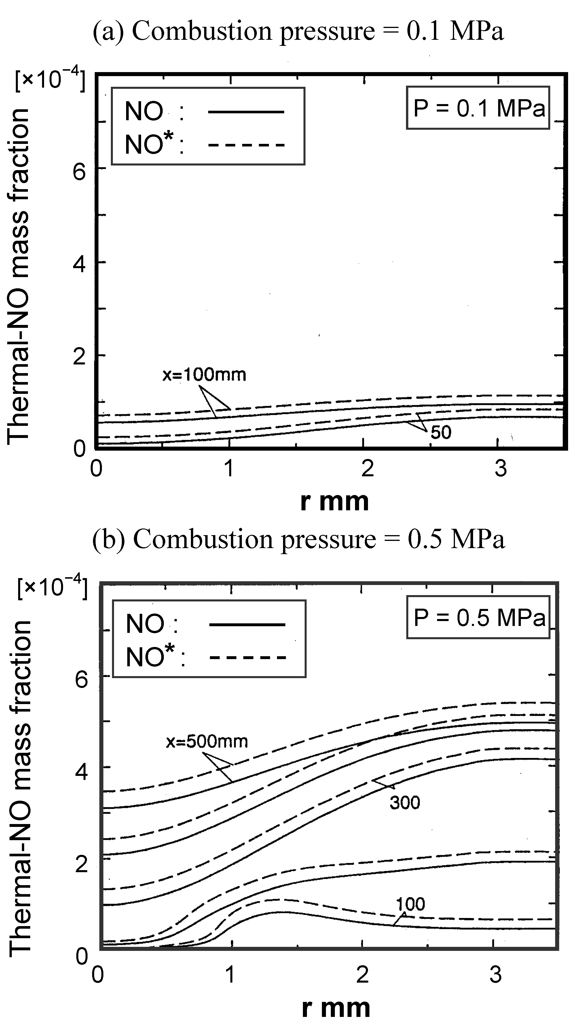
Thermal-NOx emission characteristics

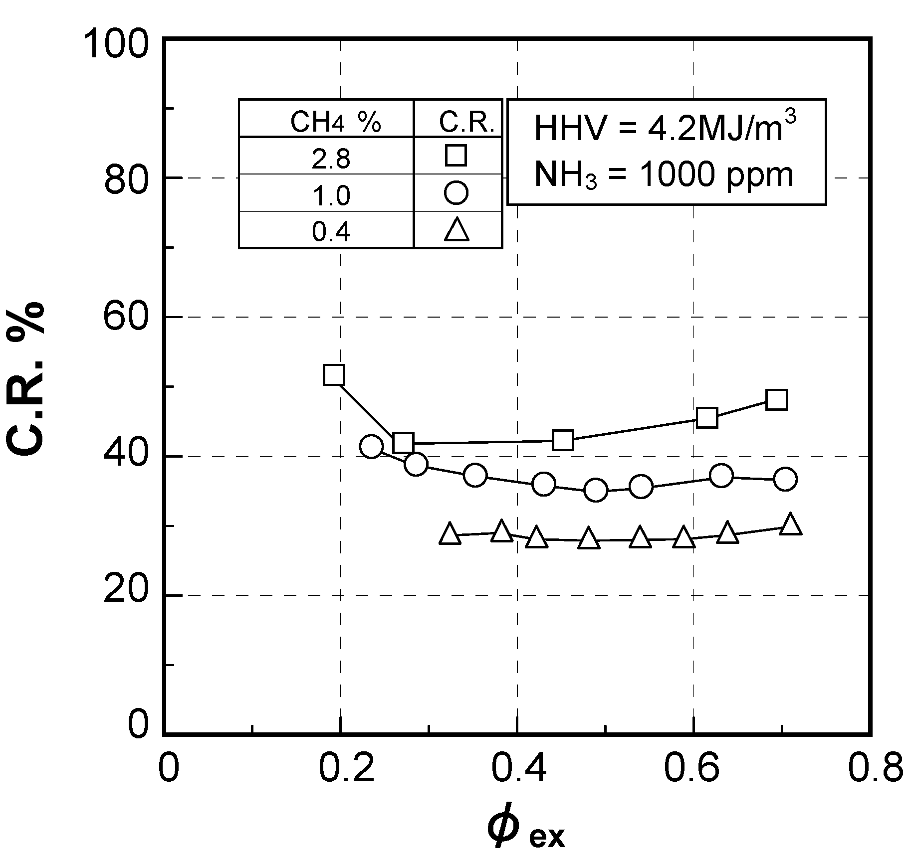
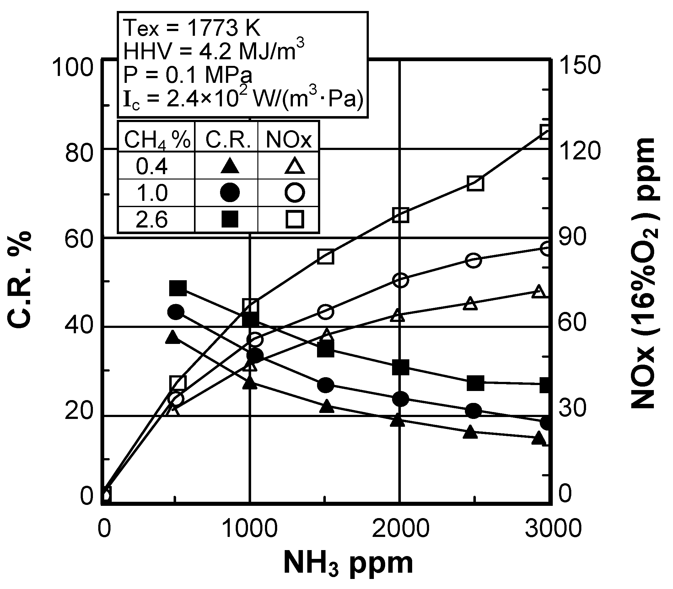
Fuel-NOx emission characteristics
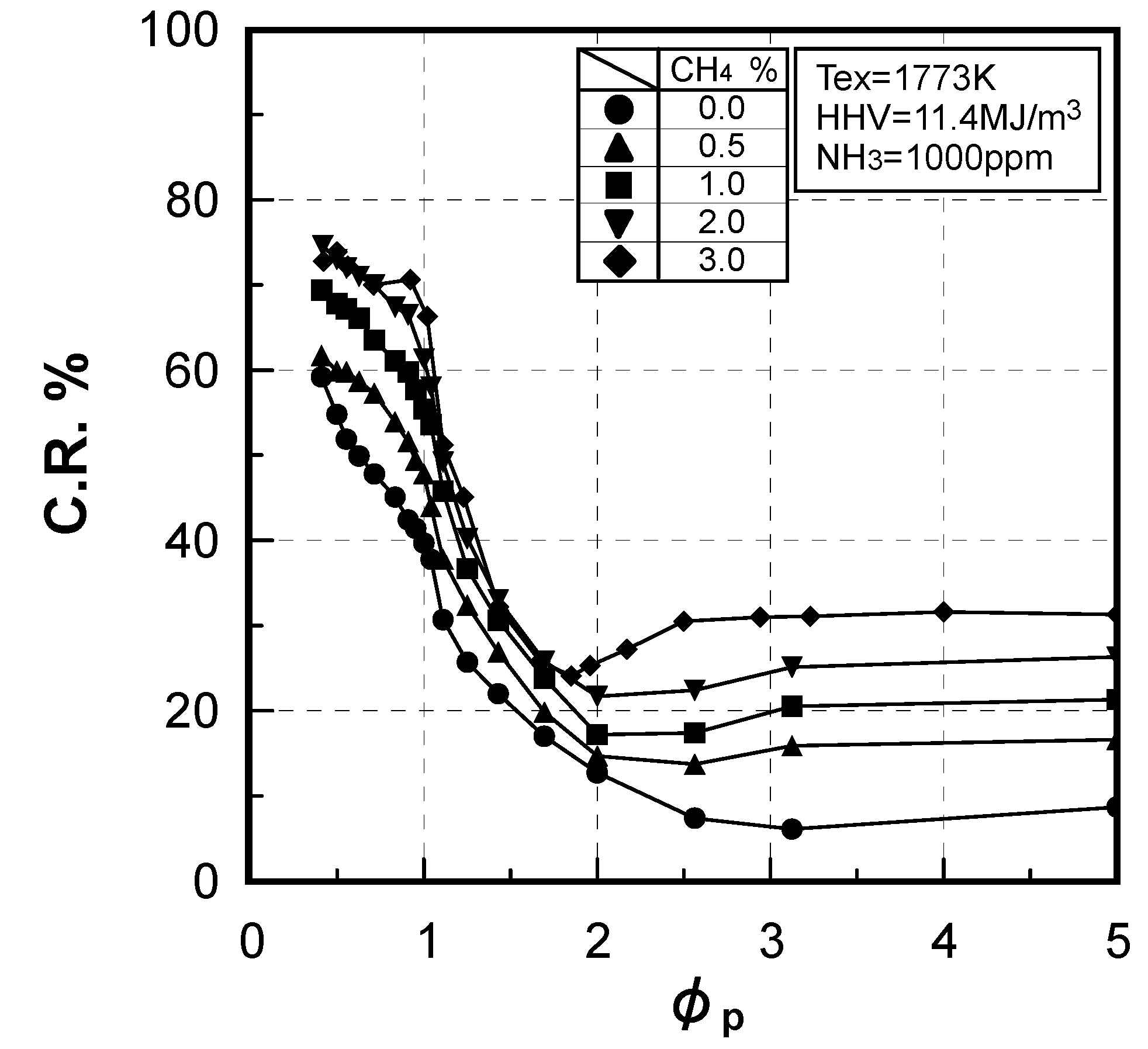
(1) Effect of CH4 constituent

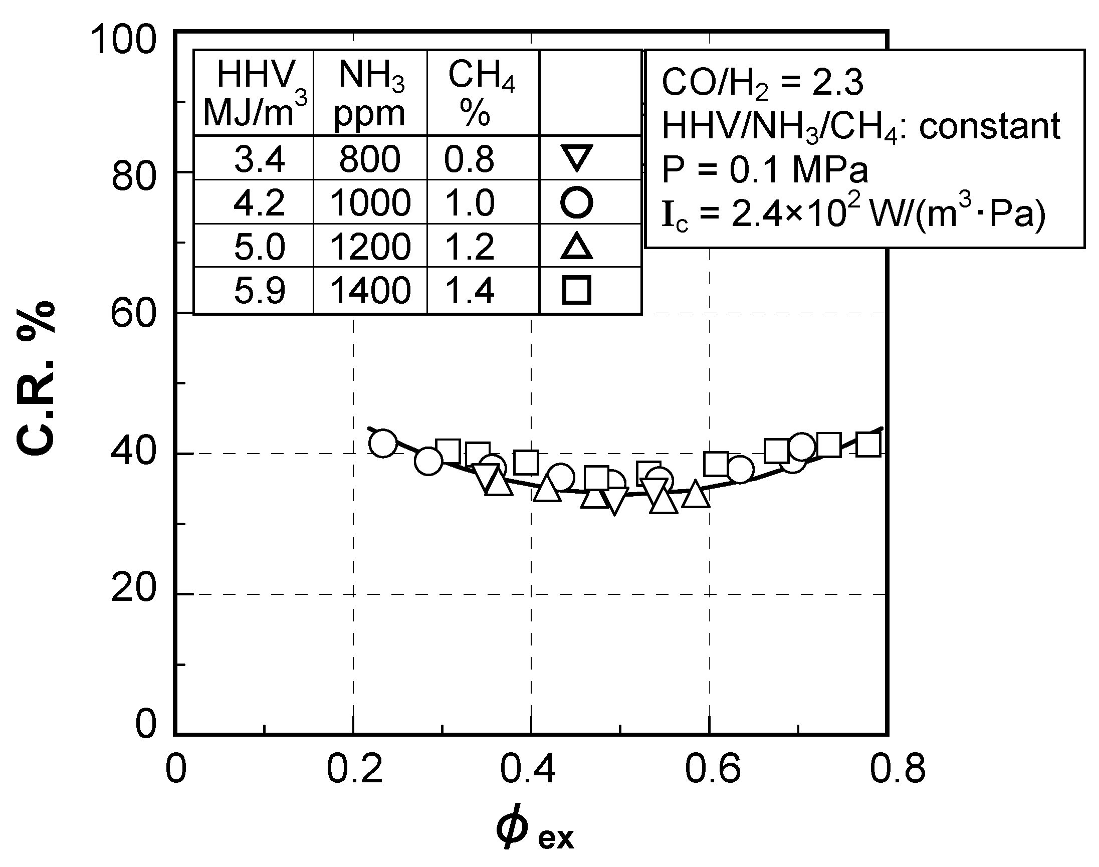
(2) Effect of fuel calorific value
(3) Effect of fuel-bound nitrogen

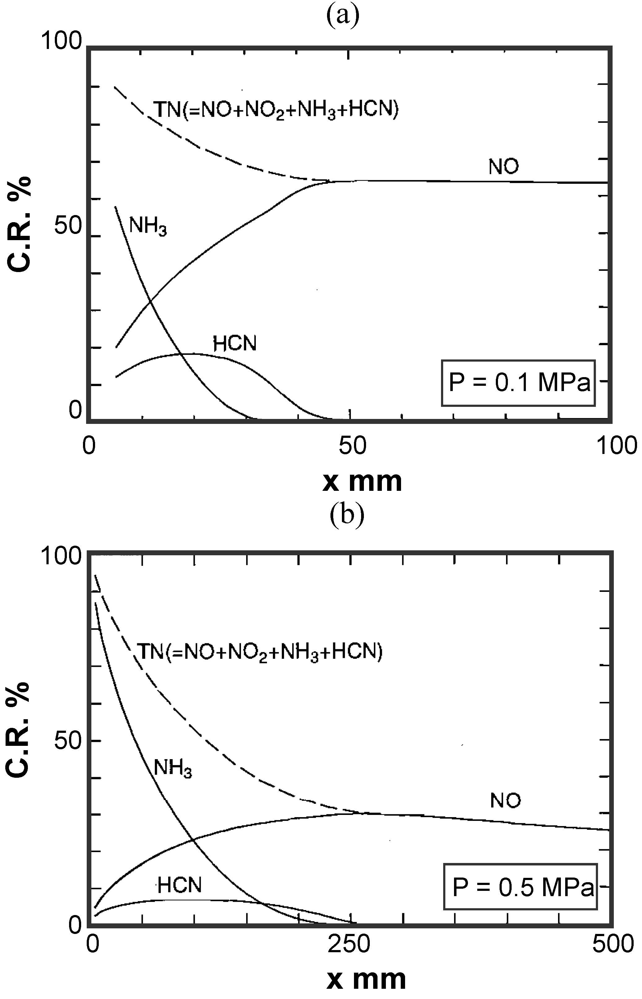
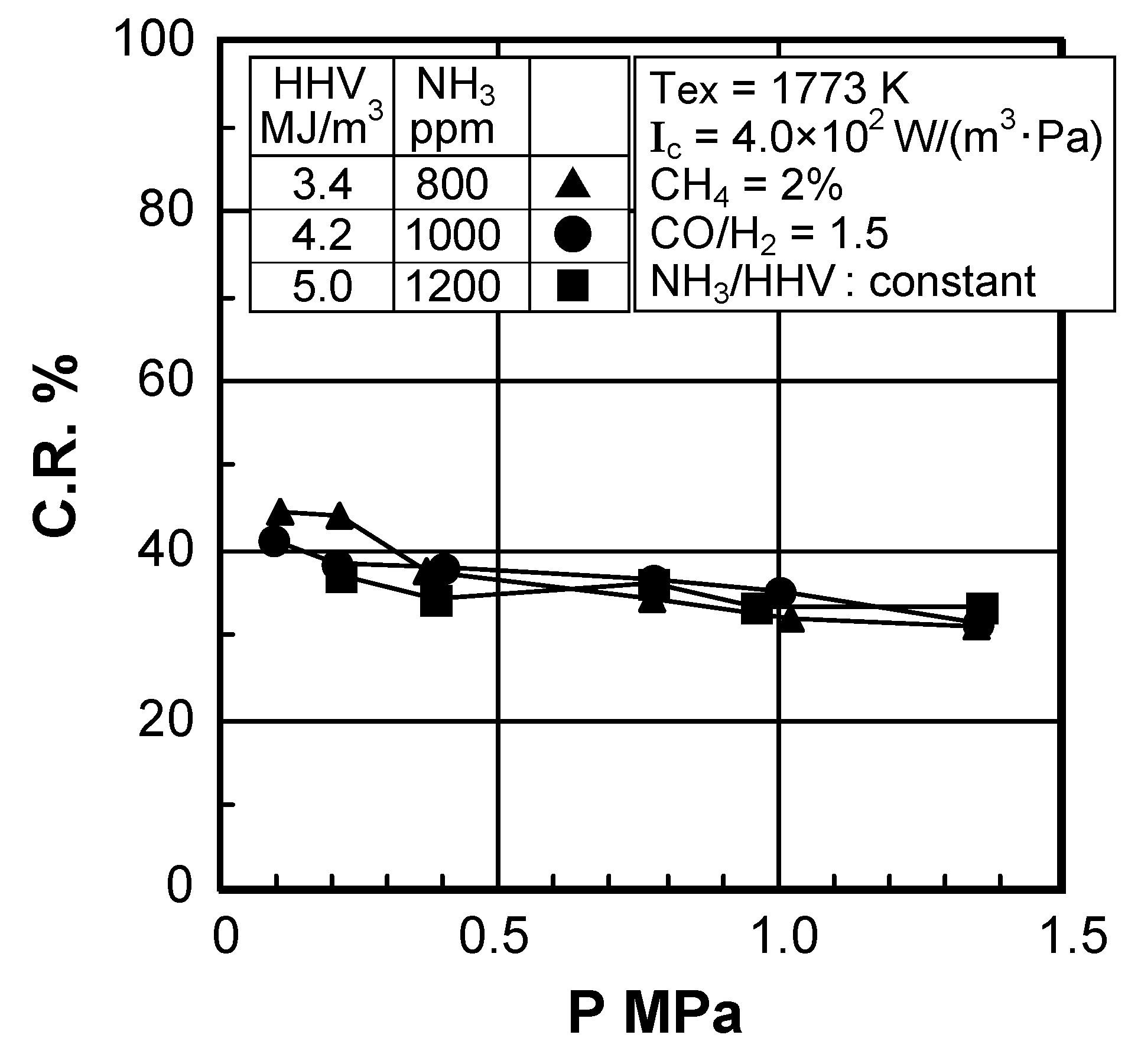
(4) Effect of pressure
- CO = 18.3vol%, H2 = 6.9vol%, CH4 = 2.5vol%,
- CO2 = 15.9vol%, N2 = 56.3vol%, NH3 = 1000 ppmv
- HHV = 4.2 MJ/m3, LHV = 4.0 MJ/m3
- Mass
- Momentum
- Species
- Energy


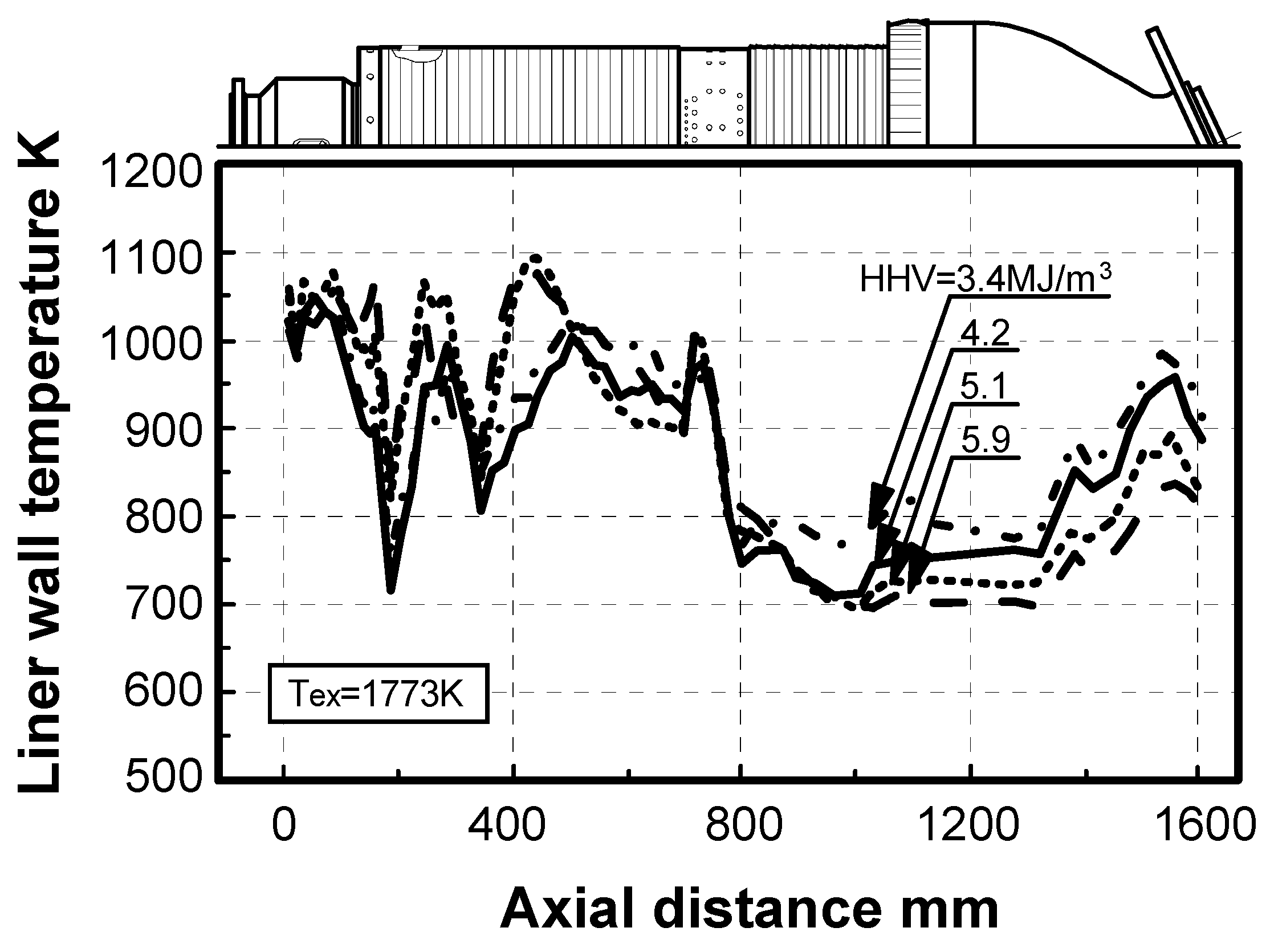
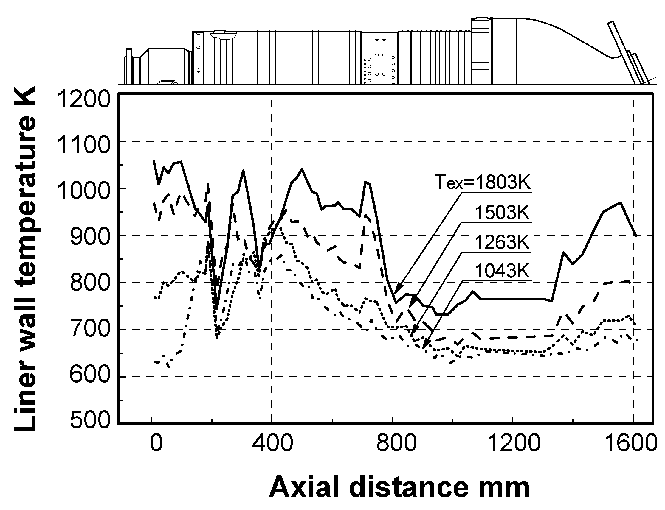
5.2.2. Thermal characteristics of combustor liner wall
Effect of fuel calorific value

Effect of exhaust gas temperature
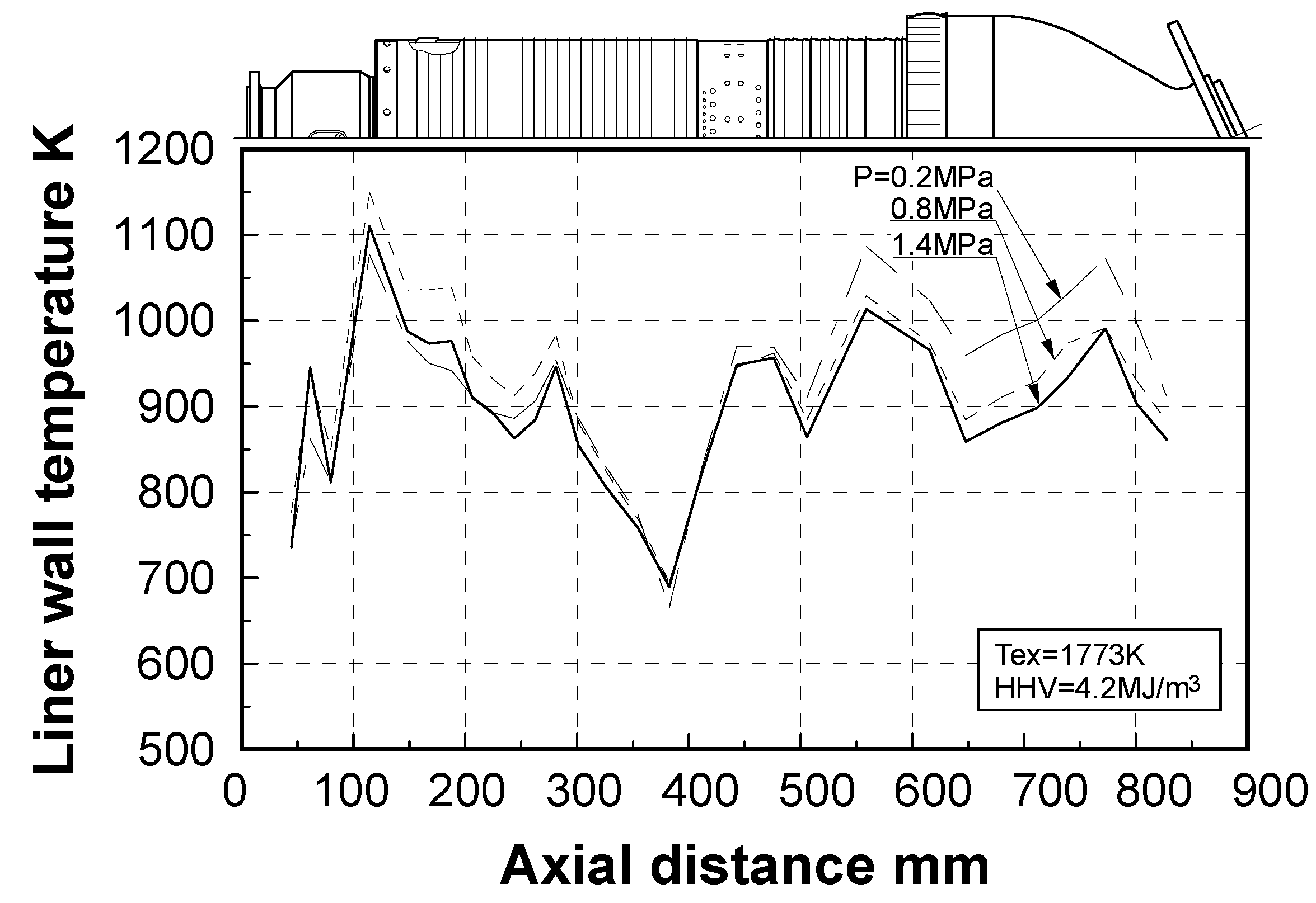
Effect of combustion pressure
6. Combustor for Oxygen-Blown Gasification System with Wet Type Synthetic Gas Cleanup
6.1. Subjects of combustor
6.2. Design concept of combustor


6.3. Test conditions
| Composition | CO | 30.4 vol% |
| H2 | 27.5 vol% | |
| CH4 | 6.8 vol% | |
| CO2 | 35.3 vol% | |
| HHV (at 273 K, 0.1 MPa) | 10.1 MJ/m3 | |
| Tair | 603 K |
| Tfuel | 583 K |
| TN2 | 333 K |
| Tex | 1700 K |
| N2 / fuel ratio | 0.3 kg/kg |
| P | 1.4 MPa |
| Combustion Intensity | 2.2 × 10² W/(m3 ·Pa) |
6.4. Test results


7. Combustor for Oxygen-Blown Gasification System with Hot/Dry Type Synthetic Gas Cleanup
7.1. Subjects of combustor
- (1)
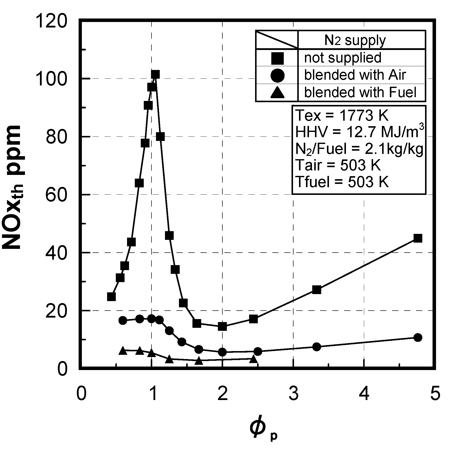
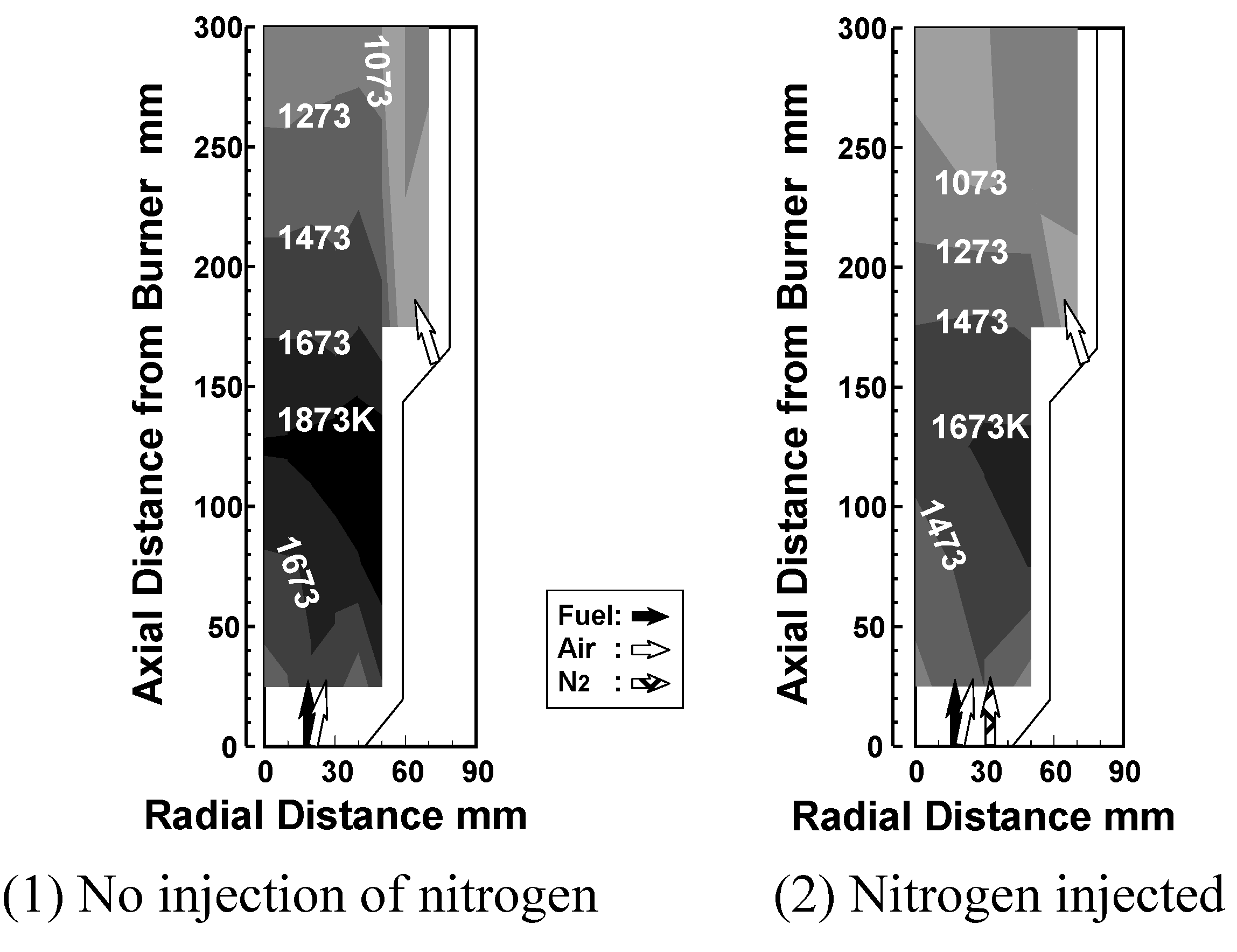
- Low NOx-emission technology: Thermal-NOx emissions produced by thermochemical reactions, mainly of the Zel’dovich NO mechanism using nitrogen injection, and fuel-NOx emissions originating from NH3 using a two-stage combustion, must be simultaneously restrained.
- (2)
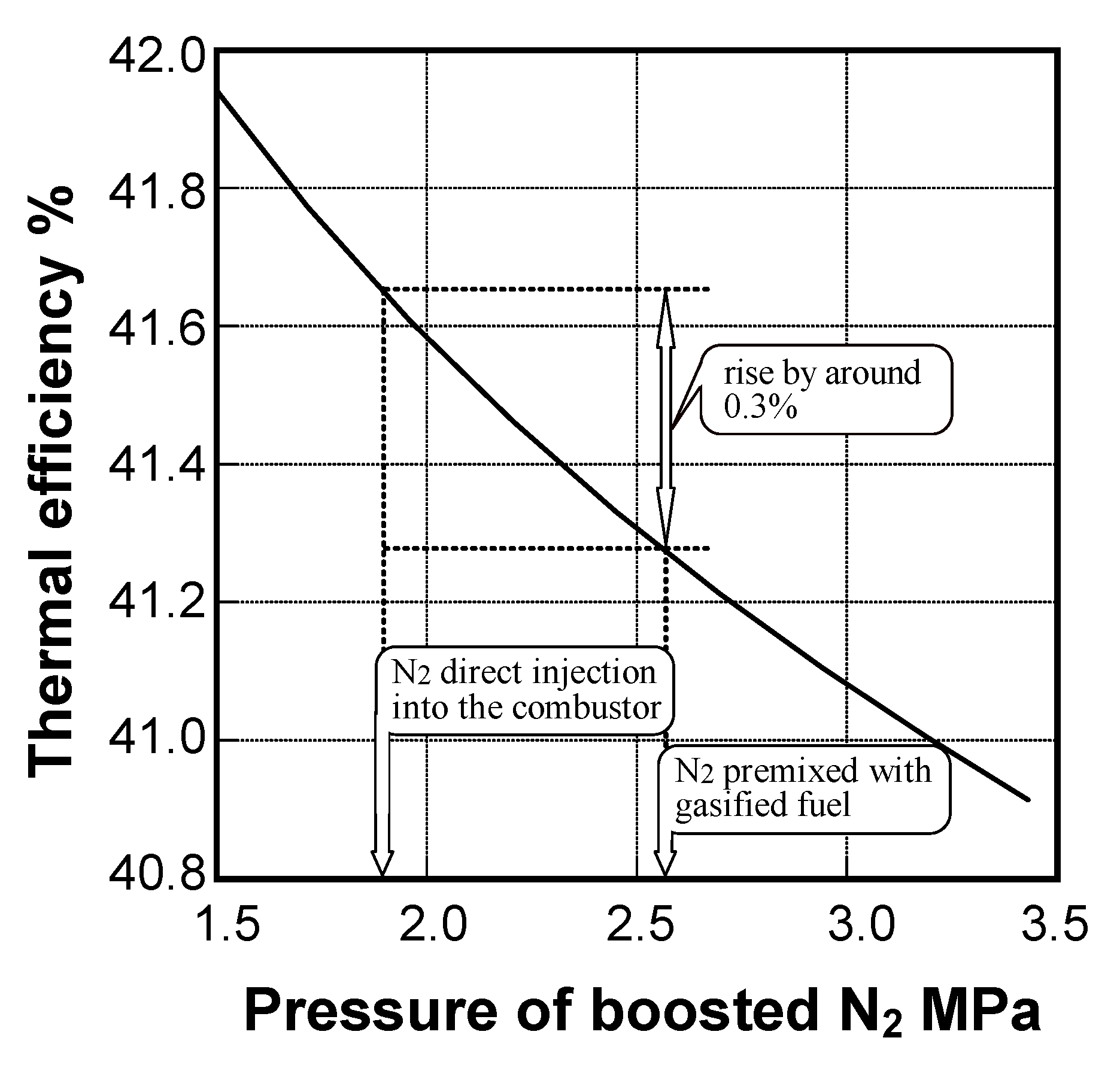
- Higher thermal efficiency: Nitrogen injection must be tailored so as to decrease the power to compress nitrogen, which is returned into the gas turbine in order to recover a part of the power used for the air-separation unit.
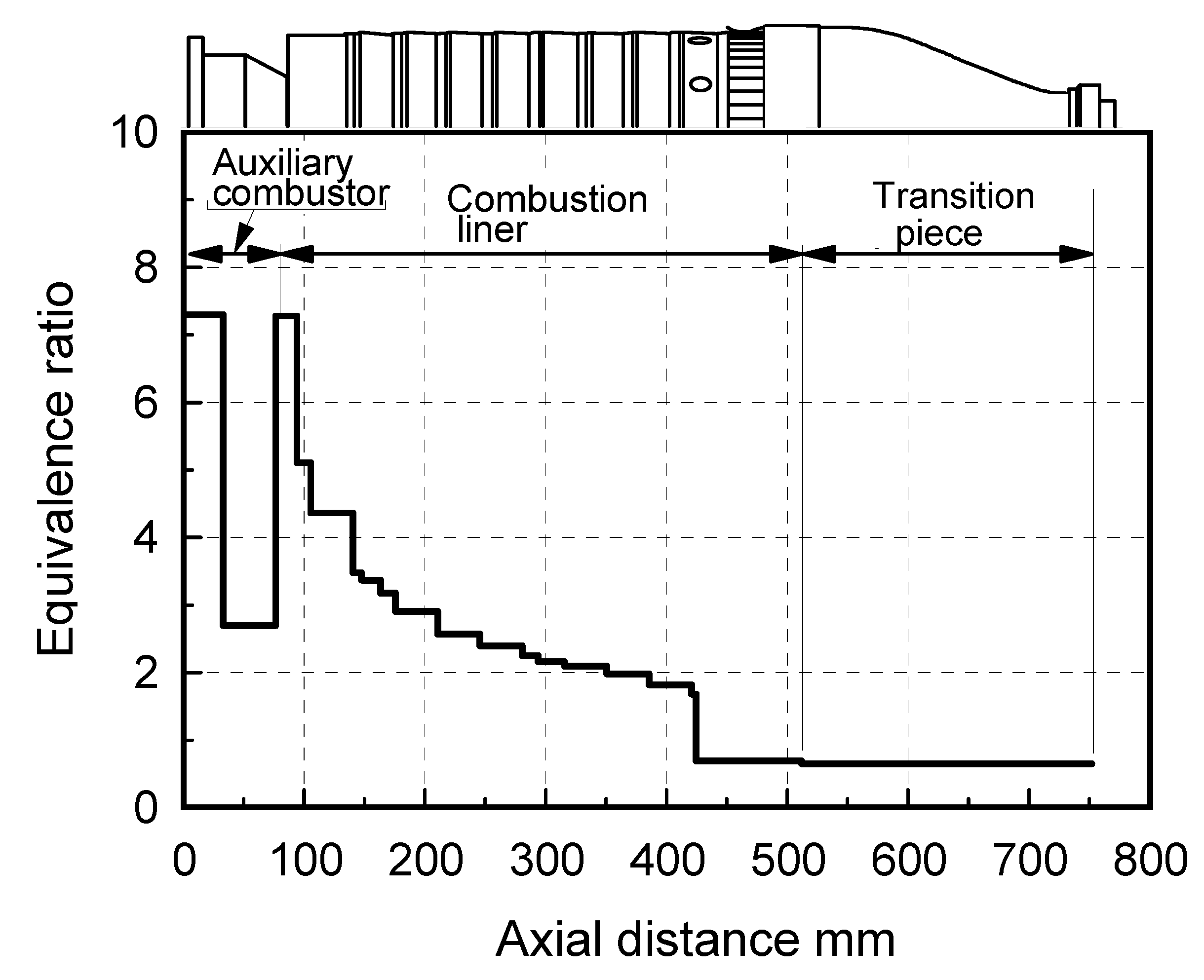
7.2. Design concept of combustor
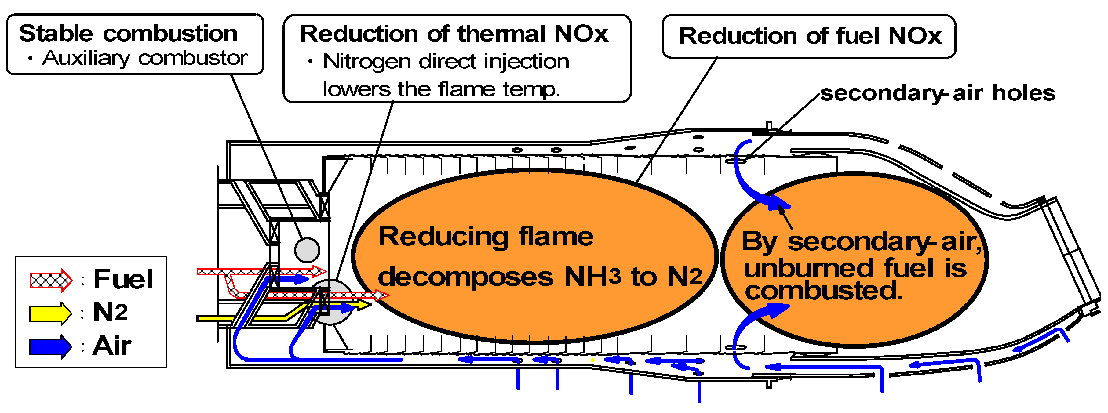

(1) Assurance of flame stabilization
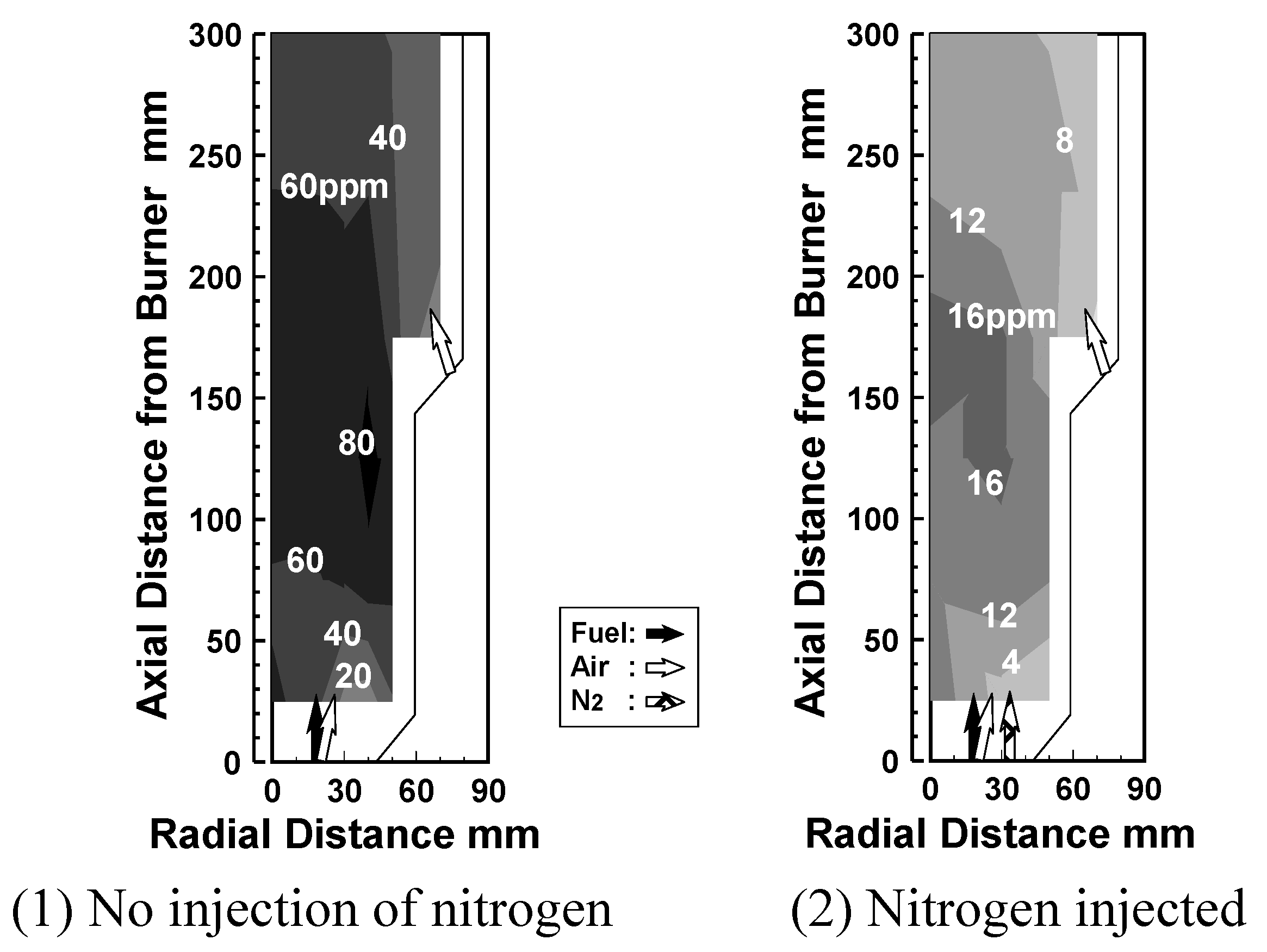
(2) Nitrogen injection

(3) Fuel-NOx / Thermal-NOx reduction
7.3. Test results
| Supplied fuel in test | Commercial gasified fuel | |
|---|---|---|
| Constituent | ||
| CO | 31.4 % | 40.9 % |
| H2 | 28.6 % | 29.9 % |
| CH4 | 0~3.0 %*1 | 0.1 % |
| CO2 | 32.0 % | 9.5 % |
| H2O | 0.0 % | 12.3 % |
| N2 | 5.0 % | 7.3 % |
| NH3 | 0~3000 ppm*2 | 500 ppm |
| HHV (at 273 K, 0.1 MPa) | 8.8 MJ/m3 | 9.0 MJ/m3 |
| LHV (at 273 K, 0.1 MPa) | 8.1 MJ/m3 | 8.2 MJ/m3 |
| Tair | 603 K |
| Tfuel | 583K |
| TN2 | 333 K |
| N2/fuel | 0.70 kg/kg |
| Tex | 1773 K |
| φex | 0.66 |
| P | 1.2 MPa |
| Ic | 4.0 × 10² W/(m3·Pa) |
| Ur | 5.6 m/s (at 273 K basis) |
| ΔP/q | 1.64 × 10² |
7.3.1. Combustion emission characteristics
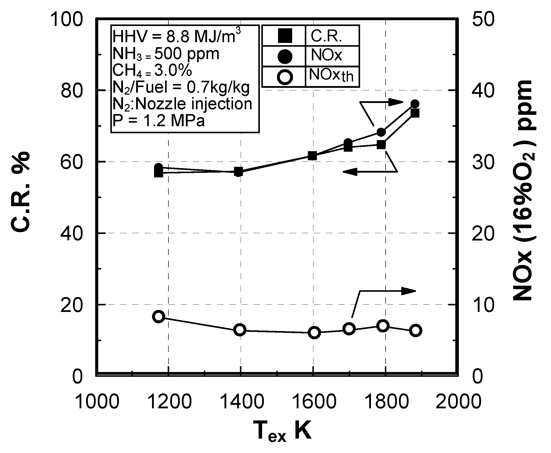
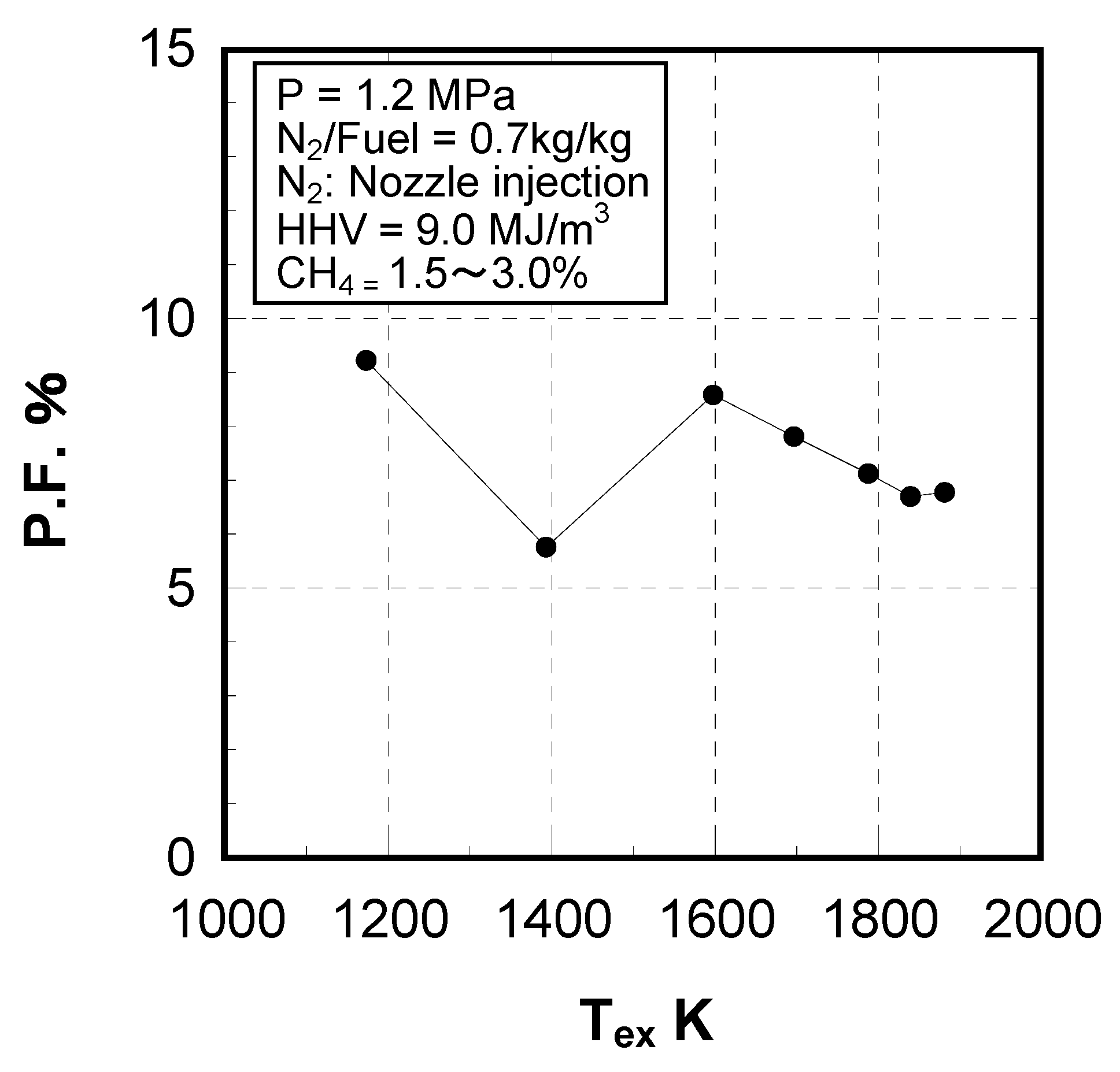
Effect of exhaust gas temperature
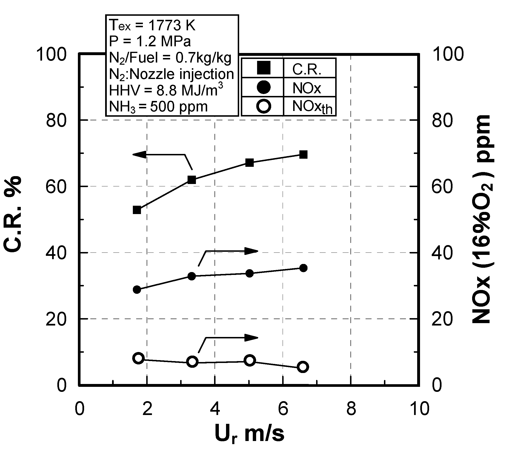
Effect of sectional flow velocity
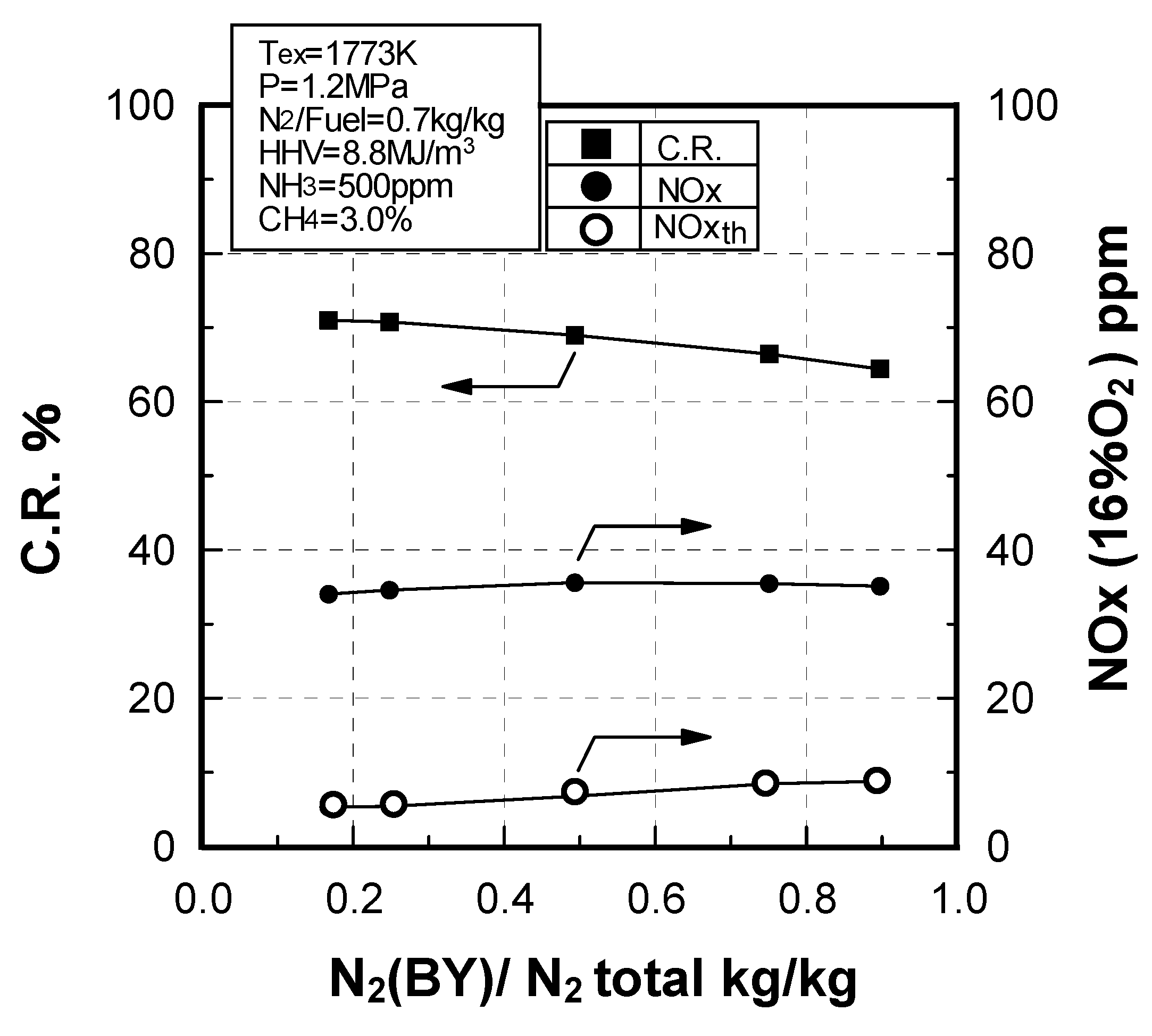
Effect of N2 bypassing way
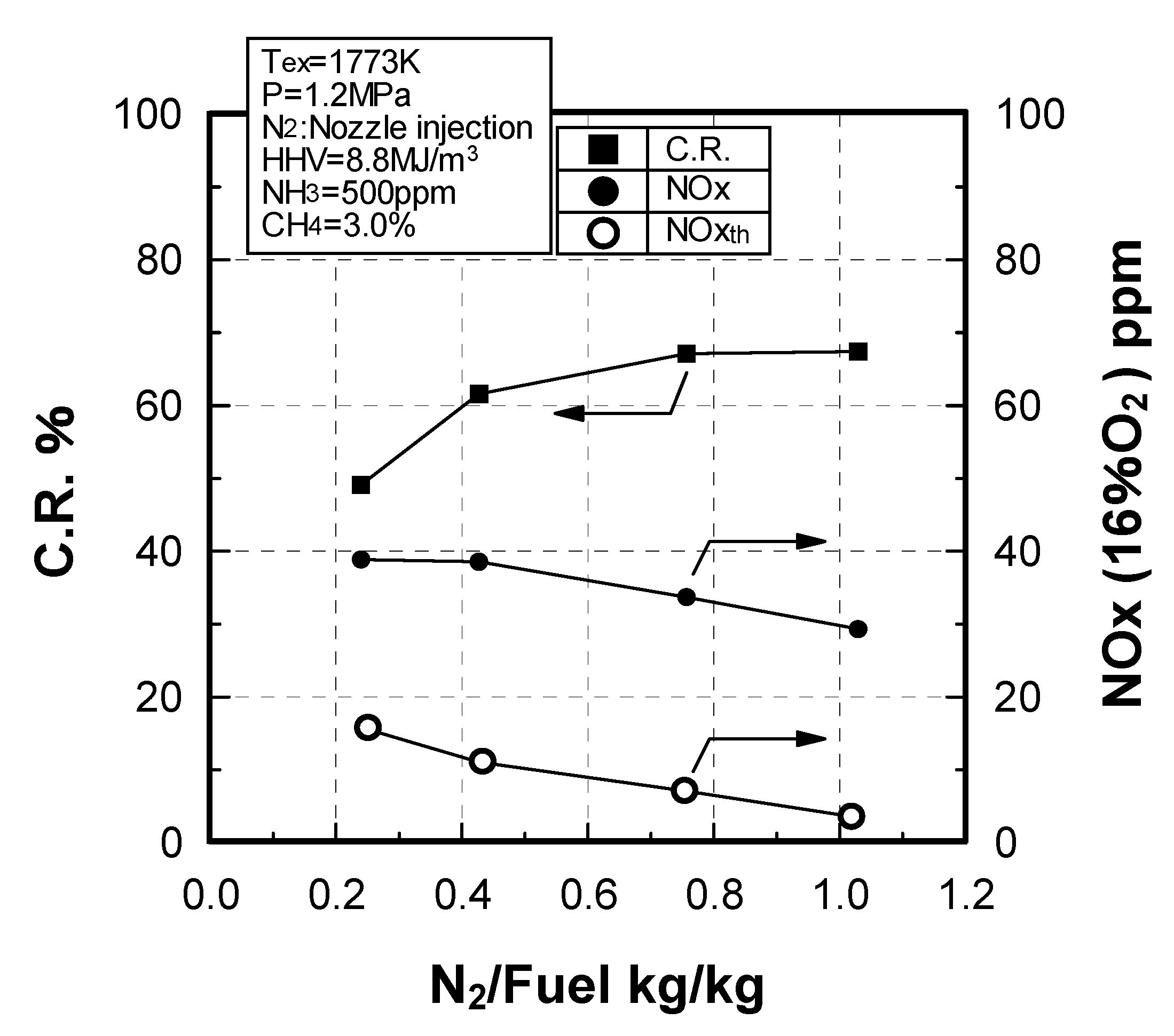
Effect of N2 flow rate
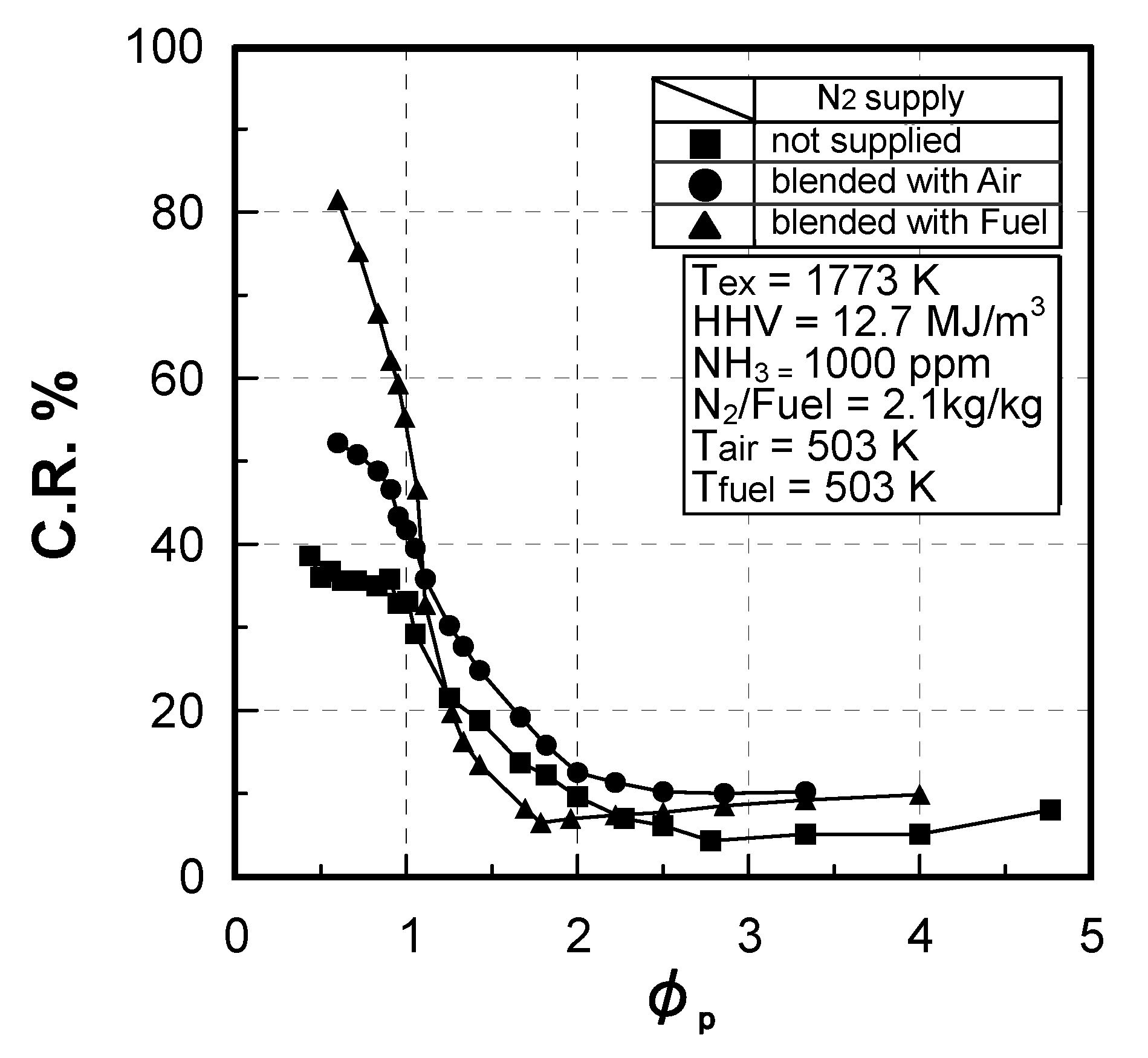
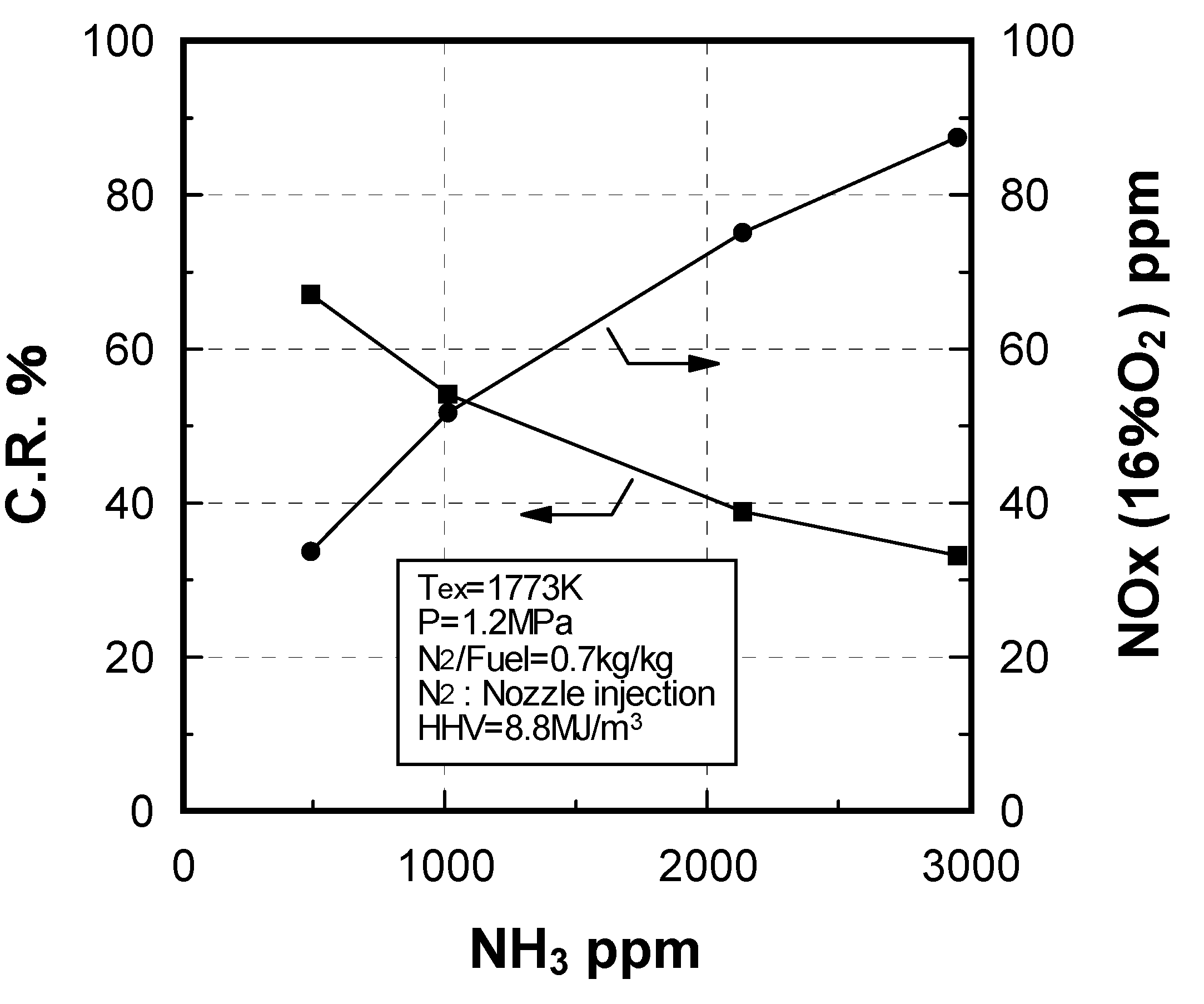
Effect of NH3 constituent

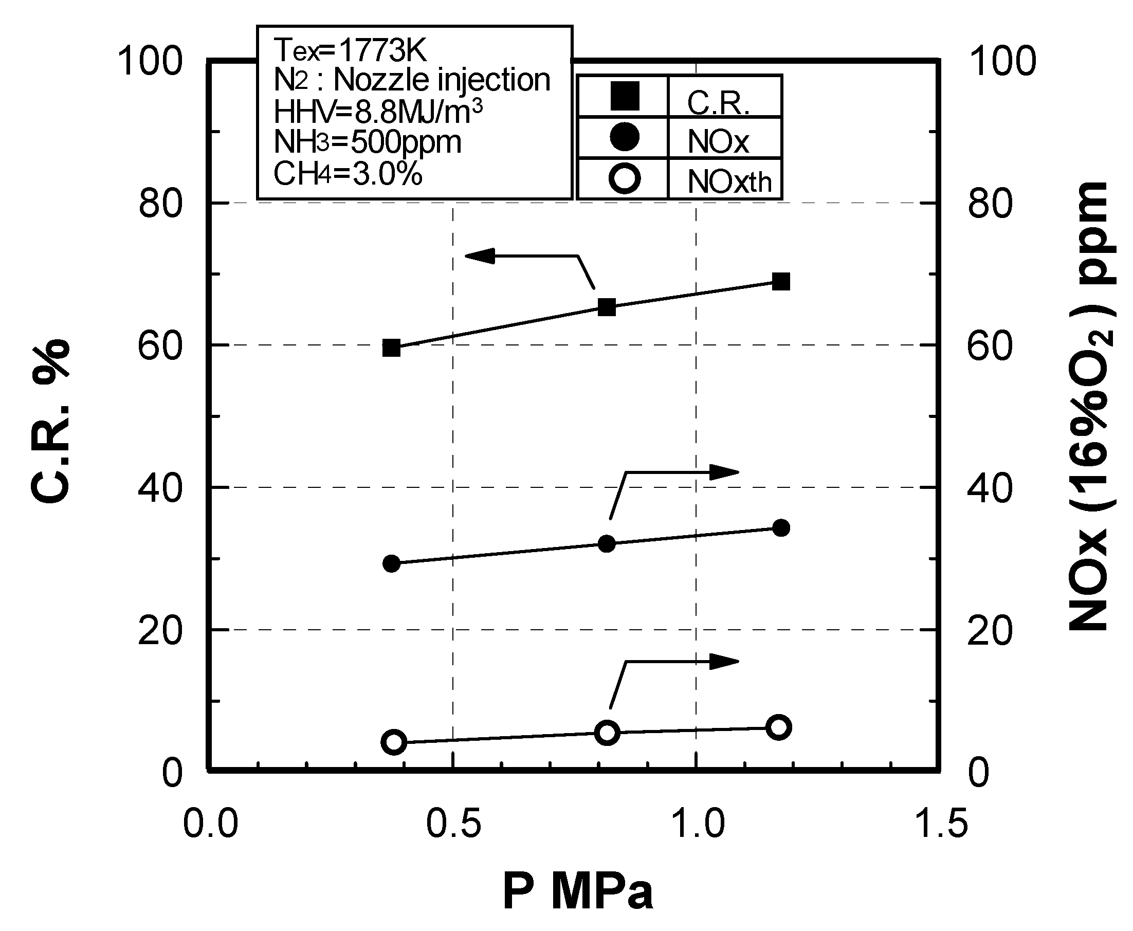
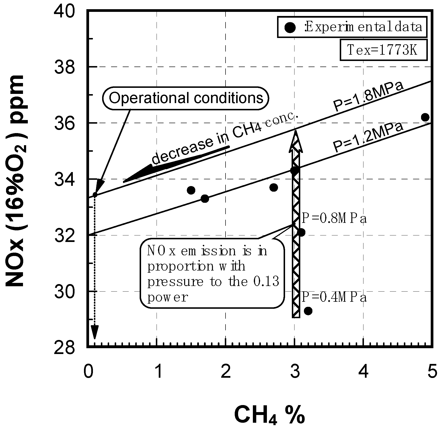
Effect of combustion pressure

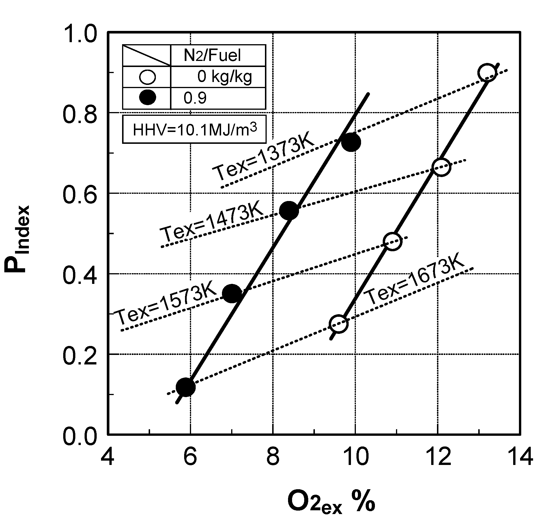
Prediction of combustor’s performance

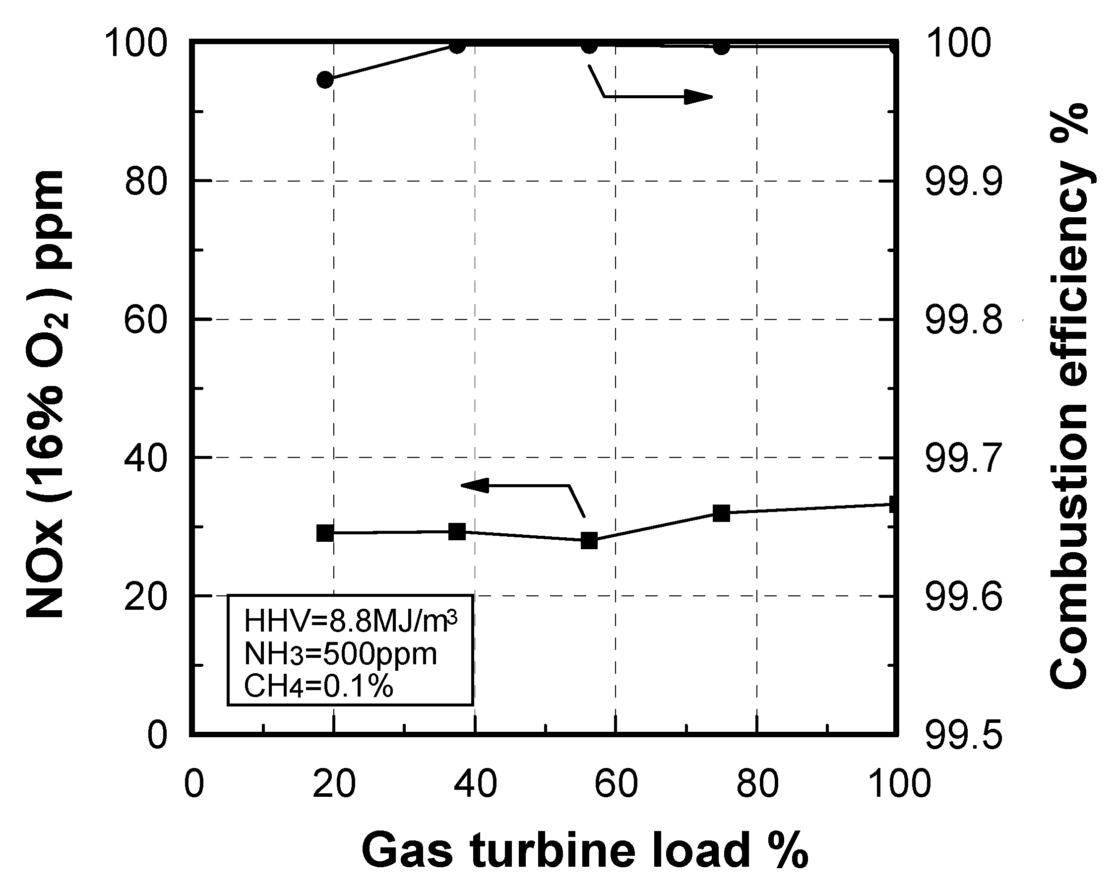
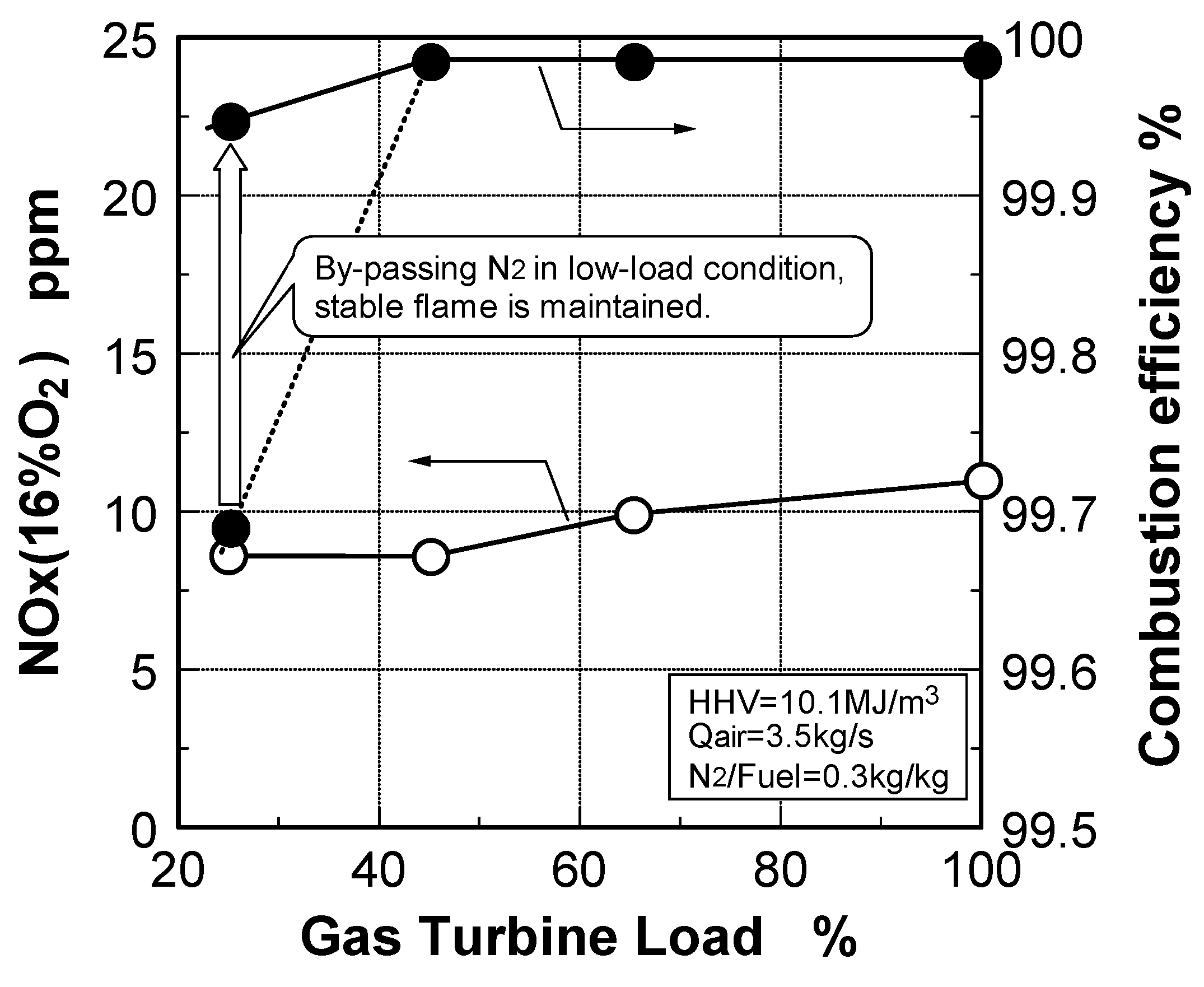
Emission characteristics in gas turbine operations

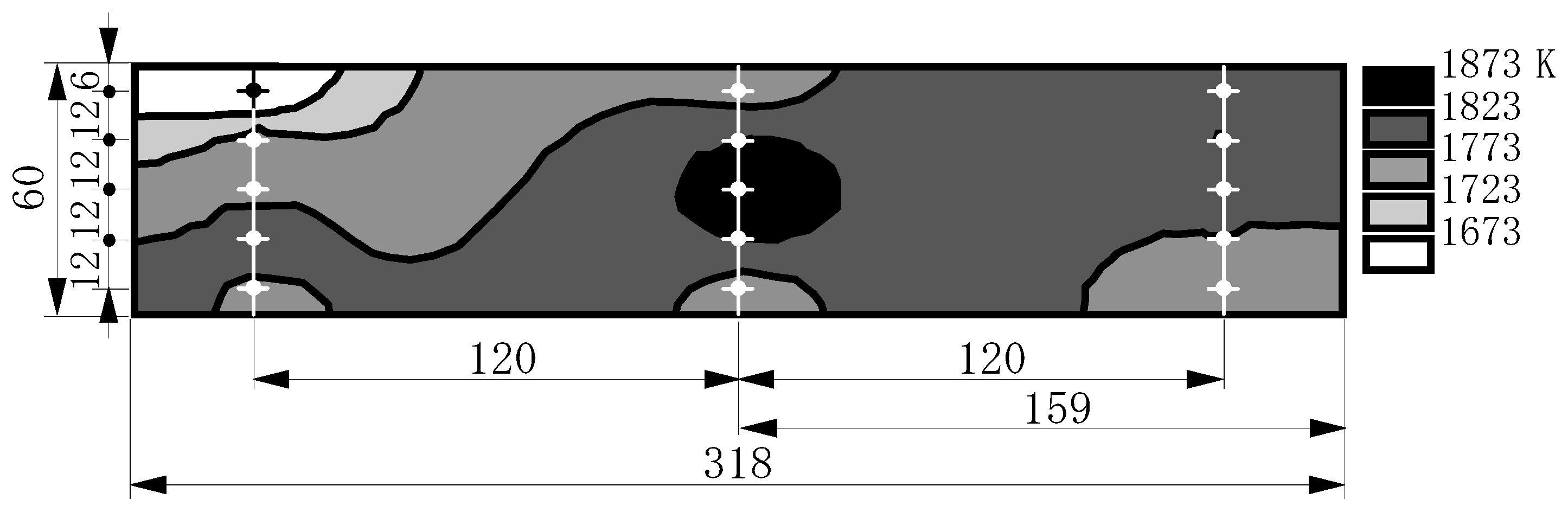
7.3.2. Thermal characteristics of combustor exhaust
8. Conclusions
- Air-blown gasifier + Hot/Dry type synthetic gas cleanup method
- Oxygen-blown gasifier + Wet type synthetic gas cleanup method
- Oxygen-blown gasifier + Hot/Dry type synthetic gas cleanup method
(1) Non-catalytic reduction of NH3
| Gasification type | Air-blown | Oxygen-blown | ||||
|---|---|---|---|---|---|---|
| Carrier type of feedstock | Dry feed | Dry or Slurry | Dry feed | |||
| Gas cleanup method | Wet type | Hot/Dry type | Wet type | Hot/Dry type | ||
Plant system
| Oxygen production unit not required | In operation now | Simpler system | |||
| +2.5 points | +4.5 points | +1.5 points*3 | +2.5 points*3 | |||
| Features of gasified fuel |
|
| ||||
| Fuel contains NH3 and a lot of fuel-NOx emissions are discharged. | Fuel contains NH3 and a lot of fuel-NOx emissions are discharged. | |||||
| Subjects of combustors’ development | Combustion stability of low calorific fuel | Reduction of thermal-NOx emissions | Reduction of thermal-NOx and fuel-NOx emissions simultaneously | |||
| Reduction of fuel-NOx emissions | ||||||
| Developed technologies | 40%~70%
| - |
| |||
Non-catalytic reduction of NH3 in fuel
| - | |||||
| Low NOx combustion methods and advantageous effect (1) Auxiliary combustor + Two stage combustion NH3/HHV*6 [ppm/(kcal/m3)] [ppm/( MJ/m3)]
| - | 1.00
2.4 × 10² 60%≦ ≦7 ppm | - | - | ||
(2) N2 direct injection
| - | - | 80%*7≦ | - | ||
(3) N2 direct injection + quick quench by combustion air
| - | - | 80%*8≦ | - | ||
(4) Auxiliary combustor + Two stage combustion + N2 direct injection
| - | - | - | ≦0.25 / 1.00≦
≦0.6 × 10² / 2.4 × 10²≦ ≦40% / 60%≦ 80%≦ | ||
| Features of developed low-NOx combustor |
|
|
| |||
| Combustors’ performance | ||||||
| Evaluation items | Target | |||||
| Rated exhaust temperature | 1773 K (1500 °C) | 1673 K (1400 °C) | 1773 K | 1873 K (1600 °C) | ||
| Combustion efficiency | ≧99.5% | ≧99.99% (CO ≦ 20 ppm) | ≧99.99% (CO ≦ 20 ppm) | ≧99.99% (CO ≦ 20 ppm) | ||
| NOx emissions*1 Total NOx*5 | ≦60 ppm | - | ≦60 ppm*2 | - | ≦34ppm*4 | ≦40 ppm*4 |
| Thermal-NOx | ≦10 ppm | ≦7 ppm | ≦8 ppm~11 ppm | ≦7 ppm | ≦8 ppm | |
| Pattern factor (P.F.*10) at rated load condition | ≦15% | ≦7% | ≦13% | ≦7% | ≦7% | |
| Maximum temperature of Liner wall | ≦850 °C | ≦1123 K (850 °C) | ≦1123 K | ≦1123 K | ≦1123 K | |
Remarks
HHV: corrected at 273 K, 0.1 MPa. |
|
|
| |||
| ||||||
(2) The advantage of low NOx combustion
- Two-stage combustion was effective for decreasing fuel-NOx and thermal-NOx emissions; the primary equivalence ratio was set depending on CH4 concentration in the fuels.
- Adopting the auxiliary-combustion chamber was effective for stabilizing combustion of low calorific fuel in reducing flame.
- In oxygen-blown medium-Btu fuels, the combustion method, in which direct injection of surplus N2 by-product from the oxygen production unit was combined with rapid dilution by combustion air, was effective in reducing thermal-NOx emissions.
- The surplus N2 direct injection method improved plant thermal efficiency by 0.3 points.
- To simultaneously reduce thermal-NOx and fuel-NOx emissions, the method that combined surplus N2 direct injection with two-stage, reducing combustion was effective. It is also necessary to adopt an auxiliary-combustion chamber for stable combustion.
Air-blown IGCC
Oxygen-blown IGCC
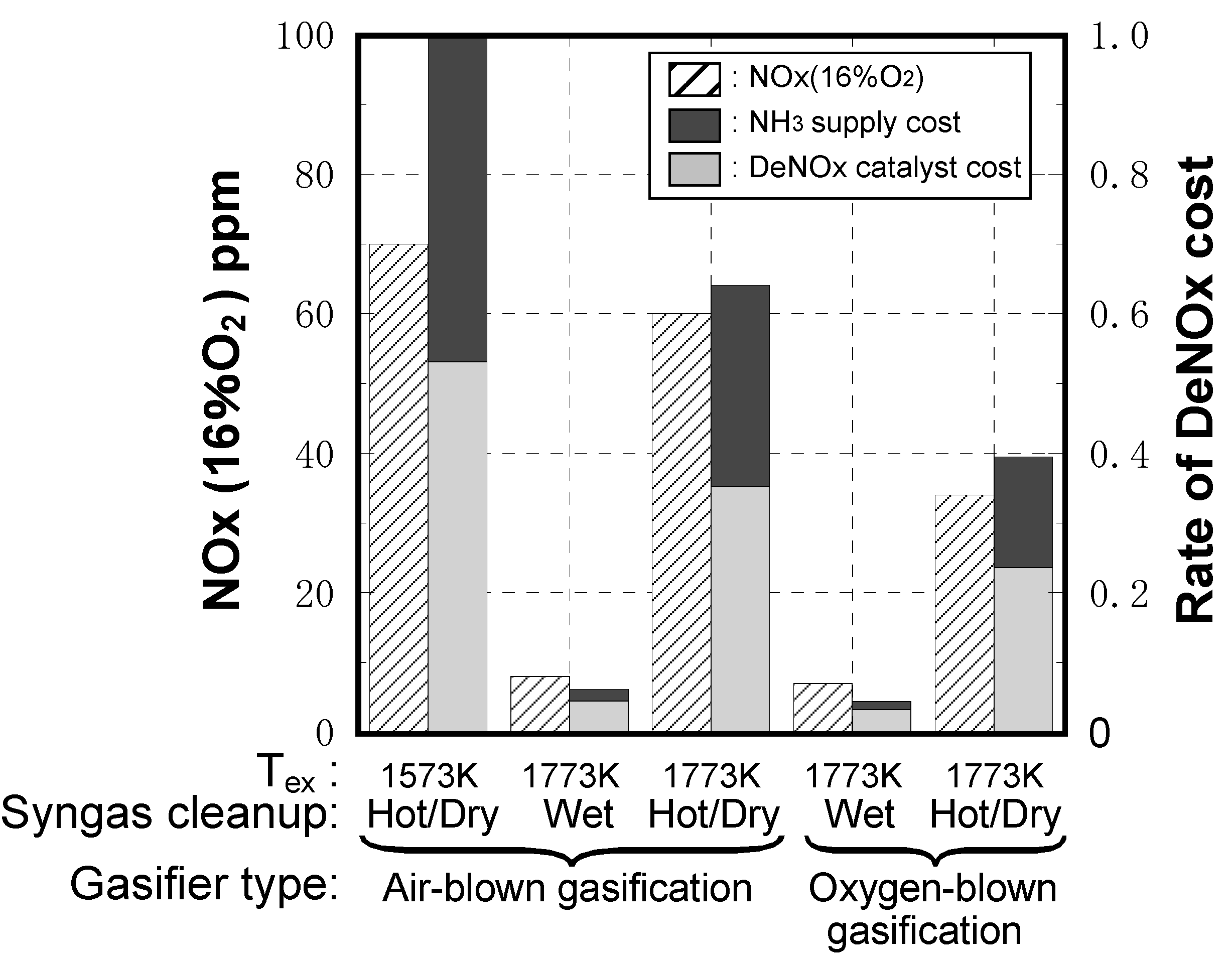
Economical evaluation

- IGCC plant output: 250 MW class
- IGCC plant operation rate: 24 hours × 333 days per year
- NH3 concentrations: NH3 concentrations in the cases of air-blown gasified fuel and oxygen-blown gasified fuel are set at 1000 ppm and 500 ppm, respectively.
- Rate of DeNOx cost estimation: NOx removal efficiency, NH3 supply quantity and NOx removal catalyst quantity are different for each type IGCC. DeNOx facility is based on conventional denitration equipment; spatial velocities at DeNOx rates of 28%, 72%, 83% and 90% are set at 220,000, 50,000, 33,000 and 20,000 [hour−1], respectively. An air-blown IGCC with hot/dry type synthetic gas cleanup adopting a 1573 K-class gas turbine is set as a standard, and the rate of DeNOx cost is the calculated proportion of each case to the standard, due to fluctuations in unit prices of catalysts’ supplied NH3, and exchange rates.
Nomenclature
| CO/H2 | Molar ratio of carbon monoxide to hydrogen in fuel |
| C.R. | Conversion rate from ammonia to NOx [%] |
| D.R. | Decomposition rate from NH3 or NO to N2 |
| HHV | Higher heating value of fuel at 273 K, 0.1 MPa basis [MJ/m3] |
| LHV | Lower heating value of fuel at 273 K, 0.1 MPa basis [MJ/m3] |
| Ic | Combustion intensity at 273 K basis [W/(m3·Pa)] |
| M | The third body |
| N2/Fuel | Nitrogen over fuel supply ratio [kg/kg] |
| NOx(16%O2) | NOx emissions corrected at 16% oxygen in exhaust [ppm] |
| NOxth | Thermal NOx emissions [ppm] |
| Pr | Reaction pressure in tubular flow reactor [MPa] |
| q | Dynamic pressure at cross-sectional surface of combustor-exit |
| Tad | Adiabatic flame temperature [K] |
| Tair | Temperature of supplied air [K] |
| Tex | Average temperature of combustor exhaust gas [K] |
| Tfuel | Temperature of supplied fuel [K] |
| Tn2 | Temperature of supplied nitrogen [K] |
| Tr | Averaged reaction temperature in tubular flow reactor [K] |
| tr | Averaged reaction time in tubular flow reactor [s] |
| Ur | Mean velocity of cross-sectional flow of air at 273 K basis [m/s] |
| φex | Average equivalence ratio at combustor exhaust |
| φp | Average equivalence ratio in primary combustion zone |
| ΔP/q | Total pressure loss coefficient (characteristic section is combustor-exit) |
References
- Petroleum Association of Japan, Statistical Information. Available online: http://www.paj.gr.jp/ (accessed on 1 February 2010).
- Kuvenvolden, K.A. Estimates of the Methane Content of Worldwide Gas-Hydrate Deposits. In Methane Hydrates: Resources in the Near Future? Japan National Oil Corporation (JNOC)—The Technology and Research Center (TRC) in Japan Oil, Gas and Metals National Corporation (JOGMEC) of Japan: Kanagawa, Japan, 1998; p. 389. [Google Scholar]
- Kuvenvolden, K.A. Methane hydrate: A Major Reservoir of Carbon in Shallow Geoshere? Chem.Geol. 1988, 71, 41–51. [Google Scholar] [CrossRef]
- Official Energy Statistics from the U.S. Government, World Electricity Data, International Energy Annual 2004, Report Released: May-July 2006. Available online: http://www.eia.doe.gov/emeu/iea/elec.html (accessed on 1 February 2010).
- Clean Coal 5 eyes BGL Gasification at Camden, Modern Power Systems; Smith, L.D. (Ed.) Wilmington Publishing: Wilmington, UK, 1993; Volume 13, Issue 8, pp. 21–24.
- Kalsall, G.J.; Smith, M.A.; Cannon, M.F. Low Emissions Combustor Development for an Industrial Gas Turbine to Utilize LCV Fuel Gas. Trans. ASME: J. Eng. Gas Turbines Power 1994, 116, 559–566. [Google Scholar]
- Ichikawa, K.; Araki, S. Test Results of the IGCC System by the 200T/D Nakoso Pilot Plant. In Proceedings of the 9th Thermal Engineering Symp., The Japan Society of Mechanical Engineers, Sapporo, Japan, July 12, 1996; pp. 11–12. (in Japanese).
- Bush, W.V.; Baker, D.C.; Tijm, P.J.A. Shell Coal Gasification Plant(SCGP-1) Environmental Performance Results; EPRI Interim Report No. GS-7397,Project 2695-1; EPRI: Palo Alto, California, USA, 1991. [Google Scholar]
- Ueda, T.; Kida, E.; Nakaya, Z.; Shikata, T.; Koyama, S.; Takagi, M. Design of the HYCOL Gasifier. In Proceedings of the CSPE-JSME-ASME International Conference on Power Engineering, Shanghai, China, May 1995; pp. 242–247.
- Cook, C.S.; Corman, J.C.; Todd, D.M. System Evaluation and L-Btu Fuel Combustion Studies for IGCC Power Generation. ASME Paper 1994. No.94-GT-366. [Google Scholar]
- Ashizawa, M.; Takahashi, T.; Taki, M.; Mori, K.; Kanehira, S.; Takeno, K. A study on Orimulsion Gasification Technology. In Proceedings of the 9th Int. Conference & Exhibition for the Power Generating Industries, Orlando, Florida, USA, December 1996; pp. 235–243.
- Moritsuka, H. Basic Principles of Various Gasification Furnaces and the Comparisons. In Gaseous Fuel Production from Biomass and Use of Its Energy; NTS: Tokyo, Japan, 2007; pp. 62–88. [Google Scholar]
- Biomass Looks Good for Gasification Process, Modern Power Systems; Smith, L.D. (Ed.) Wilmington Publishing: Wilmington, UK, 1994; Volume 14, Issue 4, pp. 61–65.
- Consonni, S.; Larson, E.D.; Berglin, N. Black Liquor-Gasifier/Gas Turbine Cogeneration. ASME Paper 1997. No.97-GT-273. [Google Scholar]
- Brown, T.D. Coal Gasification: Combined Cycles for Electricity Production. Prog. Energy Combust. Sci. 1982, 8, 277–301. [Google Scholar] [CrossRef]
- Littlewood, K. Gasification: Theory and Application. Prog. Energy Combust. Sci. 1977, 3, 35–71. [Google Scholar] [CrossRef]
- Hobbs, M.L.; Radulovic, P.T.; Smoot, L.D. Combustion and Gasification of Coals in Fixed-beds. Prog. Energy Combust. Sci. 1993, 19, 505–586. [Google Scholar] [CrossRef]
- Savelli, J.F.; Touchton, G.I. Development of a Gas Turbine Combustion System for Medium-Btu Fuel. ASME Paper 1985. No.85-GT-98. [Google Scholar]
- Roll, M.W. The Construction, Startup and Operation of the Repowered Wabash River Coal Gasification Project. In Proceedings of the 12th Annual Int. Pittsburgh Coal Conference, Pittsburgh, USA, September 1995; pp. 72–77.
- Jenkins, S.D. Tampa Electric Company’s Polk Power Station IGCC Project. In Proceedings of the 12th Annual Int. Pittsburgh Coal Conference, Pittsburgh, PA, USA, September 1995; p. 79.
- Isles, J. Europe Clean Coal Power Priorities are on Carbon Capture and Storage. In Gas Turbine World; DeBiasi, V., Ed.; Pequot Publishing: Fairfield, CT, USA, 2007; Volume 37, pp. 20–24. [Google Scholar]
- Beer, J.M. High Efficiency Electric Power Generation: The Environmental Role. Prog. Energy Combust. Sci. 2007, 33, 107–134. [Google Scholar] [CrossRef]
- Ichikawa, K. Test results of 200T/D IGCC Coal Gasification Pilot Plant. In Proceedings of the 8th DOE-METC/ANRE-NEDO Joint Technical Meeting on Surface Coal Gasification, University Park, PA, USA, October 1996.
- Kurimura, M.; Hara, S.; Inumaru, J.; Ashizawa, M.; Ichikawa, K.; Kajitani, S. A Study of Gasification Reactivity of Air-Blown Entrained Flow Coal Gasifier. In Proceedings of the 8th International Conference on Coal Science, Oviedo, Spain, September 1995; pp. 563–566.
- Nakayama, T.; Ito, S.; Matsuda, H.; Shirai, H.; Kobayashi, M.; Tanaka, T.; Ishikawa, H. Development of Fixed-Bed Type Hot Gas Cleanup Technologies for Integrated Coal Gasification Combined Cycle Power Generation; Report No.EW89015; Central Research Institute of Electric Power Industry: Ohtemachi, Chiyoda-ku, Tokyo, Japan, 1990. [Google Scholar]
- Nakata, T.; Sato, M.; Ninomiya, T.; Yoshine, T.; Yamada, M. Effect of Pressure on Combustion Characteristics in LBG-Fueled 1300 °C-Class Gas Turbine. ASME Paper 1993. No.93-GT-121. [Google Scholar]
- Hasegawa, T.; Sato, M.; Ninomiya, T. Effect of Pressure on Emission Characteristics in LBG-Fueled 1500 °C-Class Gas Turbine. Trans. ASME: J. Eng. Gas Turbines Power 1998, 120, 481–487. [Google Scholar]
- Hasegawa, T.; Sato, M. Study on NOx Formation Characteristics of Medium-Btu Coal Gasified Fuel. Trans. Jap. Soc. Mechan. Eng.: B 1997, 63, 3123–3130. (in Japanese). [Google Scholar] [CrossRef]
- Hasegawa, T.; Hisamatsu, T.; Katsuki, Y.; Sato, M.; Yamada, M.; Onoda, A.; Utsunomiya, M. A Study of Low NOx Combustion on Medium-Btu Fueled 1300 °C-Class Gas Turbine Combustor in IGCC. ASME Paper No.98-GT-331. 1998. [Google Scholar]
- Hasegawa, T.; Hisamatsu, T.; Katsuki, Y.; Sato, M.; Iwai, Y.; Onoda, A.; Utsunomiya, M. A Development of Low NOx Combustion in Medium-Btu Fueled 1300 °-Class Gas Turbine Combustor in IGCC. In Proceedings of the International Gas Turbine Congress, Kobe, Japan, November 1999; pp. 783–791.
- Hasegawa, T.; Hisamatsu, T.; Katsuki, Y.; Sato, M.; Koizumi, H.; Hayashi, A.; Kobayashi, N. Development of Low NOx Combustion Technology in Medium-Btu Fueled 1300 °C-Class Gas Turbine Combustor in IGCC. Trans. ASME: J. Eng. Gas Turbines Power 2003, 125, 1–10. [Google Scholar]
- Hasegawa, T.; Sato, M. A Study of Medium-Btu Fueled Gas Turbine Combustion Technology for Reducing both Fuel-NOx and Thermal-NOx Emissions in Oxygen-Blown IGCC. ASME Paper 2002. No.2002-GT-30666. [Google Scholar]
- Hasegawa, T. Effect of Primary Equivalence Ratio on Reducing both Fuel-NOx and Thermal-NOx Emissions of Gas Turbine Combustor for Oxygen-blown IGCC with Hot/Dry Syngas Cleanup. J. Gas Turbine Soc. Jap. 2006, 34, 452–461. [Google Scholar]
- Hasegawa, T.; Tamaru, T. Gas Turbine Combustion Technology Reducing both Fuel-NOx and Thermal-NOx Emissions in Oxygen-Blown IGCC with Hot/Dry Synthetic Gas Cleanup. Trans. ASME: J. Eng. Gas Turbines Power 2007, 129, 358–369. [Google Scholar]
- Hasegawa, T.; Sato, M.; Hisamatsu, T.; Ninomiya, T.; Koizumi, A.; Hayashi, A.; Kobayashi, N.; Yamada, M.; Iwai, Y.; Onoda, A. Developments of Gas Turbine Combustors for Air-blown and Oxygen-blown IGCC. In International Conference on Coal Science and Technology, Okinawa, Japan, October 2005. No.1D02.
- Hasegawa, T. Prediction Methodology of Fuel-NOx Emissions in Gasified Fuels’ Combustion. In Asian Congress on Gas Turbines, Komaba Meguro-ku, Tokyo, Japan, August 2009.
- Kelleher, E.G. Gasification of Kraft Black Liquor and Use of the Products in Combined Cycle Cogeneration; Phase 2 final report, DOE/CS/40341-T5; Champion Int’1. Co. for U.S. Dept. of Energy: Washington DC, USA, 1985. [Google Scholar]
- Paisley, M.A.; Anson, D. Biomass Gasification for Gas Turbine Based Power Generation. ASME paper 1997. No.97-GT-5. [Google Scholar]
- Haavisto, I. Fixed Bed Gasification of Solid Biomass Fuel. In Power Production from Biomass Ⅱ with Special Emphasis on Gasification and Pyrolysis Rⅅ Sipila, K., Korhonen, M., Eds.; Technical Research Centre of Finland: Espoo, Finland, 1996; Volume164, pp. 127–132. [Google Scholar]
- Regenbogen, R.W. Demkolec IGCC Project Update. In Proceedings of the 12th Annual Int. Pittsburgh Coal Conference, Pittsburgh, PA, USA, September 1995; p. 78.
- Krishnan, G.N.; Wood, B.J.; Sanjurjo, A.A. Study of Ammonia Removal in Coal Gasification Processes; Topical Report: Literature Review, Report No.DOE/MC/23087-2504; U.S. Department of Energy: Morgantown, WV, USA, 1987.
- Temkin, M.I.; Pyzhev, V. Kinetics of Ammonia Synthesis on Promoted Iron Catalysts. Acta. Physicochim. URSS 1940, 12, 327. [Google Scholar]
- Amano, A.; Taylor, H. The Decomposition of Ammonia on Ruthenium, Rhodium and Palladium Catalysts Supported on Alumina. J. Amr. Chem. Soc. 1954, 76, 4201. [Google Scholar] [CrossRef]
- Ståhl, K.; Neergaard, M.; Nieminen, J. Progress report: Varnamo Biomass Gasification Plant. In Gasification Technologies Conference, San Francisco, CA, USA, October, 1999.
- Noordally, E.; Przybylski, L.M.; Witton, J.J. Catalytic Conversion of NH3 to N2 in Gasified Biomass Fuel. In 5th Int. Workshop on Catalytic Combustion, Seoul, Korea, April 29–May 1, 2002; pp. 73–74.
- Dixon-Lewis, G.; Willians, D.J. The Oxidation of Hydrogen and Carbon Monoxide, chapter 1. In Comprehensive Chemical Kinetics; Bamford, C.H., Tipper, C.F.H., Eds.; Elsevier Pub. Co.: Amsterdam, The Netherlands, 1969. [Google Scholar]
- Ishizuka, S.; Tsuji, H. An Experimental Study of Effect of Inert Gases on Extinction of Laminar Diffusion Flames. In Proceedings of the 18th Symp.(Int.) on Combust., Waterloo, Canada, August 1980; pp. 695–703.
- Cohen, N. Flammability and Explosion Limits of H2 and H2/CO: A Literature Review; Aerospace Report No.TR-92(2534)-1; the Aerospace Corporation: El Segundo, CA, USA, September 10 1992. [Google Scholar]
- Morgan, G.H.; Kane, W.R. Some Effects of Inert Diluents on Flame Speeds and Temperatures. In Proceedings of the 4th Symp.(Int.) on Combust., Cambridge, MA, USA, September 1952; pp. 313–320.
- Coward, H.F.; Jones, G.E. Flammability Characteristics of Combustion Gases and Vapors; Bulletin 627; U.S. Bureau of Mines: Washington DC, USA, 1971.
- Ishibasi, Y.; Oomori, T.; Uchiyama, Y. Experimental Study on Swirl Flame of Low-Calorific Gas. In Proceedings of the 6th Annual Conference. Gas Turbine Soc., Tokyo, Japan, June 1978; pp. 7–11. (in Japanese).
- Folsom, B.A.; Courtney, C.W.; Heap, M.P. The Effects of LBG Composition and Combustor Characteristics on Fuel NOx Formation. Trans. ASME: J. Eng. Power 1980, 102, 459–467. [Google Scholar] [CrossRef]
- Drake, M.C.; Pitz, R.W.; Correa, S.M.; Lapp, M. Nitric Oxide Formation from Thermal and Fuel-bound Nitrogen Sources in a Turbulent Nonpremixed Syngas Flame. In Proceedings of the 20th Symp.(Int.) Combust., Ann Arbor, MI, USA, August 1984; pp. 1983–1990.
- Merryman, E.L.; Levy, A. NOx Formation in CO Flames; Report No.EPA-600/2-77-008c; Battelle-Columbus Laboratories: Columbus, OH, USA, January 1997. [Google Scholar]
- Miller, J.A.; Branch, M.C.; McLean, W.J.; Chandler, D.W.; Smooke, M.D.; Kee, R.J. The Conversion of HCN to NO and N2 in H2-O2-HCN-Ar Flames at Low Pressure. In Proceedings of the 20th Symp.(Int.) Combust., Ann Arbor, MI, USA, August 1984; pp. 673–684.
- Song, Y.H.; Blair, D.W.; Simisnski, V.J.; Bartok, W. Conversion of Fixed Nitrogen to N2 in Rich Combustion. In Proceedings of the 18th Symp.(Int.) on Combust., Waterloo, Canada, August 1980; pp. 53–63.
- White, D.J.; Kubasco, A.J.; LeCren, R.T.; Notardonato, J.J. Combustion Characteristics of Hydrogen-Carbon Monoxide Based Gaseous Fuels. ASME Paper 1983. No.83-GT-142. [Google Scholar]
- Sato, M.; Nakata, T.; Yamauchi, K. NOx Emission Characteristics of Coal-Derived Low BTU Gas Fuel. J. Fuel Soc. Jap. 1990, 69, 952–959. (in Japanese). [Google Scholar] [CrossRef]
- Nakata, T.; Sato, M. Reaction Analysis of Coal Gaseous Fuel in a Gas Turbine Combustor. J. Jap. Inst. Energy 1991, 71, 34–41. (in Japanese). [Google Scholar] [CrossRef]
- Yamauchi, K.; Sato, M.; Nakata, T. The Effect of CH4 Contained in Coal Gas Fuel on NOx Formation. Trans. Jap. Soc. Mechanic. Eng. B 1991, 57, 811–818. (in Japanese). [Google Scholar] [CrossRef]
- Nakata, T.; Sato, M.; Hasegawa, T. Reaction Kinetics of Fuel NOx Formation for Gas Turbine Conditions. Trans. ASME: J. Eng. Gas Turbines Power 1998, 120, 474–480. [Google Scholar]
- Martin, F.J.; Dederick, P.K. NOx from Fuel Nitrogen in Twostage Combustion. In Proceedings of the16th Symp. (Int.) on Combust., Cambridge, MA, August 1976; pp. 191–198.
- Yamagishi, K.; Nozawa, M.; Yoshie, T.; Tokumoto, T.; Kakegawa, Y. A Study of NOx emission Characteristics in Twostage Combustion. In Proceedings of the 15th Symp. (Int.) on Combust., Tokyo, Japan, August 1974; pp. 1157–1166.
- Pillsbury, P.W.; Cleary, E.N.G.; Singh, P.P.; Chamberlin, R.M. Emission Results from Coal Gas Burning in Gas Turbine Combustors. Trans. ASME: J. Eng. Power 1976, 98, 88–96. [Google Scholar] [CrossRef]
- Clark, W.D.; Folsom, B.A.; Seeker, W.R.; Courtney, C.W. Bench Scale Testing of Low-NOx LBG Combustors. Trans. ASME: J. Eng. Power 1982, 104, 120–128. [Google Scholar]
- Battista, R.A.; Farrell, R.A. Development of an Industrial Gas Turbine Combustor Burning a Variety of Coal-Derived Low Btu Fuels and Distillate. ASME Paper 1979. No.79-GT-172. [Google Scholar]
- Beebe, K.W.; Symonds, R.A.; Notardonato, J. Evaluation of Advanced Combustion Concepts for Dry NOX Suppression with Coal-Derived, Gaseous Fuels. In IEEE/ASME/ASCE Joint Power Generation Conference, Denver, CO, USA, October 1982. CONF-821018-4.
- Döbbeling, K.; Eroglu, A.; Winkler, D.; Sattelmayer, T.; Keppel, W. Low NOx Premixed Combustion of MBtu Fuels in a Research Burner. ASME paper 1996. No.96-GT-126. [Google Scholar]
- Döbbeling, K.; Knöpfel, H.P.; Polifke, W.; Winkler, D.; Steinbach, C.; Sattelmayer, T. Low NOx Premixed Combustion of MBtu Fuels Using the ABB Double Cone Burner (EV Burner). ASME Paper 1994. No.94-GT-394. [Google Scholar]
- Zanello, P.; Tasselli, A. Gas Turbine Firing Medium Btu Gas from Gasification Plant. ASME Paper 1996. No.96-GT-8. [Google Scholar]
- Becker, B.; Schetter, B. Gas Turbines Above 150 MW for Integrated Coal Gasification Combined Cycles (IGCC). Trans. ASME: J Eng. Gas Turbines Power 1992, 114, 660–664. [Google Scholar]
- Walsh, P.M. A Review of Ammonia and Hydrogen Cyanide Concentrations in Low and Medium-Btu Coal Gases; Contract No. EF-77-S-01-2762; Princeton Univ.: Princeton, NJ, USA, 1979. [Google Scholar]
- Lyon, R.K. Method for the Reduction of the Con-centration of NO in Combustion Effluents Using Ammonia. US Patent No. 3,900,554, 1975. [Google Scholar]
- Lyon, R.K. Thermal DeNOx: How It Works. In Hydrocarbon Processing; Gulf Publishing: Houston, TX, October 1979; pp. 109–112. [Google Scholar]
- Lyon, R.K.; Hardy, J.E. Discovery and Development of the Thermal DeNOx Process. Ind. Eng. Chem. Fundam. 1986, 25, 19–24. [Google Scholar] [CrossRef]
- Muzio, L.J.; Arand, J.K.; Teixeira, D.P. Gas Phase Decomposition of Nitric Oxide in Combustion Products. In Proceedings of the 16th Symp. (Int.) on Combust., Cambridge, MA, USA, August 1976; pp. 199–207.
- Broga, T.R. Method for Reducing NOx Emissions from Combustion Processes. US Patent No. 4,335,084, 1982. [Google Scholar]
- Arand, J.K. Urea Reduction of NOx in Fuel Rich Combustion Effluents. US Patent No. 4,325,924, 1982. [Google Scholar]
- Chen, S.L.; Cole, J.A.; Heap, M.P.; Kramlich, J.C.; McCarthy, J.M.; Pershing, D.W. Advanced NOx Reduction Processes Using -NH and -CN Compounds in Conjunction with Staged Air Addition. In Proceedings of the Twenty-Second Symp. (Int.) on Combust., Seattle, WA, USA, August 1988; pp. 1135–1145.
- Kasaoka, S.; Sasaoka, E.; Ikoma, M. Noncatalytic Oxidation of Ammonia in NH3-CO-H2-O2-H2O-N2 System (Consideration on Combustion for Low NOx-formation). J. Chem. Soc. Jap. 1980, 8, 1274–1281. (in Japanese). [Google Scholar]
- Zhao, Z.S.; Arai, N.; Hasatani, M. Effect of Coexisting H2 and CO on the Gas-Phase Formation of NO, NO2 and N2O via NH3. Kagaku Kogaku Ronbunshu (ISSN 0386-216X). 1990, 16, 1180–1186. (in Japanese). [Google Scholar] [CrossRef]
- Hasegawa, T.; Sato, M.; Nakata, T. A Study of Combustion Characteristics of Gasified Coal Fuel. Trans. ASME: J. Eng. Gas Turbines Power 2001, 123, 22–32. [Google Scholar] [CrossRef]
- Sarofim, A.F.; Williams, G.C.; Modell, M.; Slater, S.M. Conversion of Fuel Nitrogen to Nitric Oxide in Premixed and Diffusion Flames. AIChE Symp. Series 1975, 71, 51–61. [Google Scholar]
- Kato, K.; Fujii, K.; Kurata, T.; Mori, K. Formation and Control of Nitric Oxide from Fuel Nitrogen: 1st Report, Experimental and Modeling Studies of Fuel NO in Premixed Flat Flames. Trans. Jap. Soc. Mechanic. Eng. Series 2 1976, 42, 582–591. (in Japanese). [Google Scholar] [CrossRef]
- Fenimore, C.P. Formation of Nitric Oxide from Fuel Nitrogen in Ethylene Flames. Combust. Flame 1972, 19, 289–296. [Google Scholar] [CrossRef]
- Takagi, T.; Ogasawara, M.; Daizo, M.; Tatsumi, T. Fundamental Studies on NO and CO Emissions and their Control in Combustion Systems: 4th Report, Characteristics of NO Formation in Turbulent Diffusion Flames and Behaviors of HCN. Trans. Jap. Soc. Mechanic. Eng. Series 2 1977, 43, 1426–1439. (in Japanese). [Google Scholar] [CrossRef]
- Pratt, D.T.; Bowman, B.R.; Crowe, C.T. Prediction of Nitric Oxide Formation in Turbojet Engines by PSR Analysis. AIAA paper 1971. No.71–713. [Google Scholar]
- Fenimore, C.P. Effects of Diluents and Mixing on Nitric Oxide from FuelNitrogen Species in Diffusion Flames. In Proceedings of the 16th Symp. (Int.) on Combust., Cambridge, MA, USA, August 1976; pp. 1065–1071.
- Heap, M.P.; Tyson, T.J.; Cichanowicz, J.E.; Gershman, R.; Kau, C.J.; Martin, G.B.; Lanier, W.S. Environmental Aspects of Low BTU Gas Combustion. In Proceedings of the 16th Symp. (Int.) on Combust., Cambridge, MA, USA, August, 1976; pp. 535–545.
- Takagi, T.; Tatsumi, T.; Ogasawara, M.; Tatsumi, K. Fundamental Studies on NO and CO Emissions and their Control in Combustion Processes: 5th Report, Processes and Characteristics of NO Formation from Fuel Nitrogen. Trans. Jap. Soc. Mechanic. Eng. Series 2 1978, 44, 4282–4291. (in Japanese). [Google Scholar] [CrossRef]
- Kato, K.; Fujii, K.; Kurata, T.; Mori, K. Formation and Control of Nitric Oxide from Fuel Nitrogen: 3rd Report, Measurements in Laminar Diffusion Flames. Trans. Jap. Soc. Mechanic. Eng. Series 2 1977, 43, 280–292. (in Japanese). [Google Scholar] [CrossRef]
- Miller, J.A.; Bowman, C.T. Mechanism and Modeling of Nitrogen Chemistry in Combustion. Prog. Energy Combust. Sci. 1989, 15, 287–338. [Google Scholar] [CrossRef]
- Hasegawa, T.; Sato, M. Study of Ammonia Removal from Coal-Gasified Fuel. Combust. Flame 1998, 114, 246–258. [Google Scholar] [CrossRef]
- Glarborg, P.; Dam-Johansen, K.; Miller, J.A. The Reaction of Ammonia with Nitrogen Dioxide in a Flow Reactor: Implications for the NH2 + NO2 Reaction. Int. J. Chem. Kinet. 1995, 27, 1207–1220. [Google Scholar] [CrossRef]
- Bromly, J.H.; Barnes, F.J.; Nelson, P.F.; Haynes, B.S. Kinetics and Modeling of the H2-O2-NOx System. Int. J. Chem. Kinet. 1995, 27, 1165–1178. [Google Scholar] [CrossRef]
- Dagaut, P.; Lecomte, F.; Mieritz, J.; Glarborg, P. Experimental and Kinetic Modeling Study of the Effect of NO and SO2 on the Oxidation of CO-H2 Mixtures. Int. J. Chem. Kinet. 2003, 35, 564–575. [Google Scholar] [CrossRef]
- Smith, G.P.; Golden, D.M.; Frenklach, M.; Moriarty, N.W.; Eiteneer, B.; Goldenberg, M.; Bowman, C.T.; Hanson, R.K.; Song, S.; Gardiner, W.C., Jr.; Lissianski, V.V.; Qin, Z. Available online: http://www.me.berkeley.edu/gri_mech/ (accessed on 1 February 2010).
- Chase, M.W., Jr.; Davies, C.A.; Downey, J.R., Jr.; Frurip, D.J.; McDonald, R.A.; Syverud, A.N. JANAF Thermodynamical Tables. J. Phys. Chem. 1985, 14. [Google Scholar]
- Kee, R.J.; Rupley, F.M.; Miller, J.A. The CHEMKIN Thermodynamic Data Base; Sandia Report, SAND 87-8215B; Sandia National Laboratories: Livermore, CA, USA, 1987. [Google Scholar]
- Hindmarsh, A.C. GEAR: Ordinary Differential Equation System Solver; Lawrence Livermore Laboratory Report No. UCID-30001; Univ. California: San Francisco, CA, USA, 1974. [Google Scholar]
- Xu, Z.; Sato, M.; Hasegawa, T.; Takagi, T. Numerical Analysis of Diffusion Combustion of Coal-Gasified Fuel (Effect of Pressure on NOx Formation). JSME Int. J. Series B, Fluid Therm. Eng. 1997, 40, 439–446. [Google Scholar] [CrossRef]
- Miller, J.A.; Smooke, M.D.; Green, R.M.; Kee, R.J. Kinetic Modeling of the Oxidation of Ammonia in Flames. Combust. Sci. Technol. 1983, 34, 149–176. [Google Scholar] [CrossRef]
- Katayama, K. Heat Transfer; JSME: Tokyo-To, Japan, 1986; pp. 52–53. [Google Scholar]
- Fujii, S. Formation Mechanisms and Controls of Pollutants in Combustion System; JSME: Tokyo-To, Japan, 1980; p. 185. [Google Scholar]
- Fenimore, C.P. Formation of Nitric Oxide in Premixed Hydrocarbon Flames. In Proceedings of the 13th Symp. (Int.) on Combust., Salt Lake City, Utah, August, 1970; pp. 373–379.
- Kee, R.J.; Rupley, F.M.; Miller, J.A. Chemkin-II: A FORTRAN Chemical Kinetics Package for the Analysis of Gas-Phase Chemical Kinetics; Sandia Report, SAND 89-8009B; Sandia National Laboratories: Livermore, CA, USA, 1989. [Google Scholar]
- Kee, R.J.; Dixon-Lewis, G.; Warnatz, J.; Coltrin, M.E.; Miller, J.A. A Fortran Computer Code Package for the Evaluation of Gas-Phase Multicomponent Transport Properties; Sandia Report, SAND 86-8246; Sandia National Laboratories: Livermore, CA, USA, 1986. [Google Scholar]
- Spalding, D.B. HMT Genmix-A General Computer Program for Two-Dimensional Parabolic Phenomena; Pergamon: New York, USA, 1977. [Google Scholar]
- Xu, Z.; Sato, M.; Hasegawa, T.; Takagi, T. Numerical Analysis of Diffusion Combustion of Coal Gasified Fuel (Effect of Pressure on NOx Formation). Trans. Jap. Soc. Mechanic. Eng. Series B 1996, 62, 811–818. (in Japanese). [Google Scholar]
- Hayashi, A.; Koizumi, H.; Kobayashi, N.; Hasegawa, T.; Hisamatsu, T.; Katsuki, Y.; Sato, M. Combustion Characteristics of Gas Turbine Combustor for Medium-Btu Fuels. In Proceedings of the 13th Fall Annual Conference of The Gas Turbine Society of Japan, Onuma, Hokkaido, Japan, October 1998; pp. 125–130. (in Japanese).
- Childs, J.H.; Graves, C.C. Correlation of Turbine Engine Combustion Efficiency with Theoretical Equations. In Proceedings of the 6th Symp. (Int.) on Combust., New Haven, CT, USA, August 1956; pp. 869–878.
- Herbert, M.V. A Theoretical Analysis of Reaction Rate Controlled Systems—Part 1. In AGARD Combustion Researches and Reviews; Buttterworths: London, UK, 1957; pp. 76–111. [Google Scholar]
- Sawyer, R.F.; Cernansky, N.P.; Oppenheim, A.K. Factors Controlling Pollutant Emissions from Gas Turbine Engines, Atmospheric Pollution by Aircraft Engines. AGARD CPP-125 1973, 22, 1–13. [Google Scholar]
- Blazowski, W.S.; Walch, D.E.; Mach, K.D. Prediction of Aircraft Gas Turbine NOx Emission Dependence on Engine Operating Parameters and Ambient Conditions. AIAA Paper 1973. No.73-1275. [Google Scholar]
- Davis, L.B.; Murad, R.J.; Wilhelm, C.F. Emission and Controll of NOx in Industrial Gas Turbine Combustors: Experimental Results. In Proceedings of the 66th annual AIChE Meeting, Philadelphia, PA, USA, November 1973.
- Tamaru, T. Research and Development of Combustors for Gas Turbine and Jet Engines in the National Aerospace Laboratory; Technical memorandum No. NAL TM-676; National Aerospace Laboratory: Tokyo-To Japan, 1995; pp. 32–34. (in Japanese) [Google Scholar]
- Takagi, T.; Ogasawara, M.; Daizo, M.; Tatsumi, T. NOx Formation from Nitrogen in Fuel and Air during Turbulent Diffusion Combustion. In Proceedings of the 16th Symp. (Int.) Combust., Cambridge, Massachusetts, August 1976; pp. 181–189.
- Longwell, J.P.; Weiss, M.A. High Temperature Reaction Rates in Hydrocarbon Combustion. Industr. Eng. Chem. 1995, 47, 1634–1643. [Google Scholar] [CrossRef]
© 2010 by the author; licensee Molecular Diversity Preservation International, Basel, Switzerland. This article is an open-access article distributed under the terms and conditions of the Creative Commons Attribution license (http://creativecommons.org/licenses/by/3.0/).
Share and Cite
Hasegawa, T. Gas Turbine Combustion and Ammonia Removal Technology of Gasified Fuels. Energies 2010, 3, 335-449. https://doi.org/10.3390/en3030335
Hasegawa T. Gas Turbine Combustion and Ammonia Removal Technology of Gasified Fuels. Energies. 2010; 3(3):335-449. https://doi.org/10.3390/en3030335
Chicago/Turabian StyleHasegawa, Takeharu. 2010. "Gas Turbine Combustion and Ammonia Removal Technology of Gasified Fuels" Energies 3, no. 3: 335-449. https://doi.org/10.3390/en3030335
APA StyleHasegawa, T. (2010). Gas Turbine Combustion and Ammonia Removal Technology of Gasified Fuels. Energies, 3(3), 335-449. https://doi.org/10.3390/en3030335