1. Introduction
Natural gas hydrates (NGHs) located under the deep sea or permafrost are a potential energy source. For example, deposits of NGHs have been reported in marine sediments in the Nankai Trough off the Pacific coast of Japan, where the water depth is more than 500 m [
1]. Estimates suggest that the reserves of NGHs correspond to several decades of supply of natural gas to Japan [
2], making it an important potential source of energy. Currently, natural gas is transported from a production site to the place of consumption mainly by a liquefied natural gas (LNG) system. However, for economic reasons an LNG system can only be applied to large gas fields. The increasing demand for natural gas requires the development of systems to transport natural gas that are more economical and practical and can be applied to small and/or medium size gas fields. An NGH system is a promising solution because hydrates can contain a large amount of gases under thermal conditions milder than those of an LNG system. Recently, a continuous NGH system has been developed to efficiently store and transport natural gases using hydrate pellets [
3,
4].
In addition to the natural gas carrier, attention has also been paid to clathrate hydrates as a novel carrier of hydrogen (H
2). H
2 hydrate has a type-II structure in the pressure range of 0.18 to 0.22 GPa at a temperature of 249 K [
5]. It was recently found that the addition of a second guest substance, such as tetrahydrofuran (THF) [
6,
7,
8,
9,
10], quaternary ammonium salts [
8,
11,
12], cyclohexanone [
13] or amines [
14] is effective in lowering the stability pressure. However, this technique is still highly discussed because the addition of second guests reduces the overall H
2 storage capacity. Most researchers have reported that the maximum amount of H
2 stored in THF + H
2 hydrates is at most 1 wt% [
10,
13,
15,
16,
17], which is a fourth of that in a pure H
2 hydrate. If the H
2 storage capacity is improved up to that expected in pure H
2 hydrate, the utilization of clathrate hydrates becomes realistic as a future engineering technology [
18]. In fact, the technique has been developed to increase the H
2 storage to 3.4 wt% in THF + H
2 hydrate [
19].
Since the materials are treated as powder or pelletized particles and the storage conditions are set at around 253 K, moderate temperatures below the melting point of ice, and atmospheric pressure for economic reasons, it is necessary to consider the sintering of hydrate particles for their easy handling. Sintering is a thermal treatment for bonding particles to a coherent, predominantly solid structure via mass transport events that often occur on the atomic scale. The bonding leads to improved strength and lower system energy [
20,
21]. Sintering is observed for snow and ice particles, especially when they are stored at temperatures near the melting point. Clathrate hydrates have a framework similar to that of ice, and thus, sintering may occur even though not only water molecules but also guest molecules are required. However, experimental investigations of sintering on clathrate hydrates are very limited [
22]. In the present study, we observed the sintering processes of clathrate hydrates to estimate how fast it progressed under several conditions below the ice point.
2. Results and Discussion
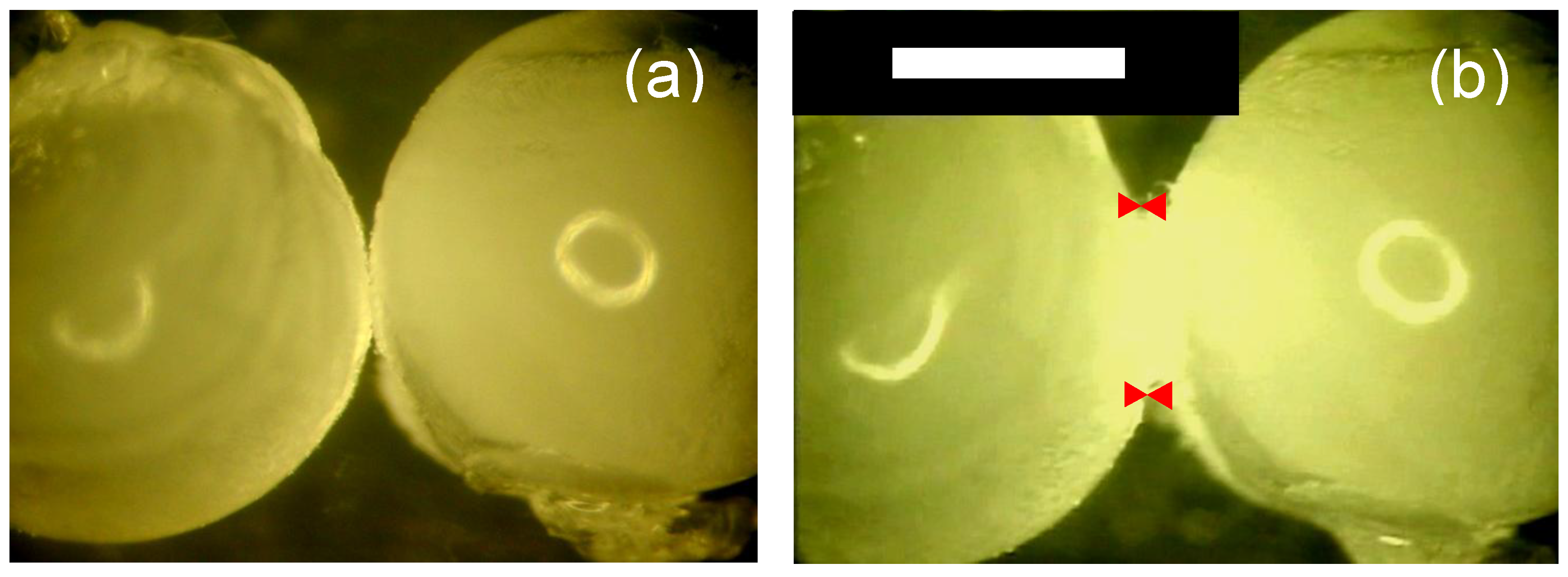
Optical microscopic images of ice particles (approximately 2 mm in diameter) showed sintering during storage at 263.1 K for 6 h (
Figure 1). The necks of the particles grew from the contact points, while the surfaces of particles became smooth.
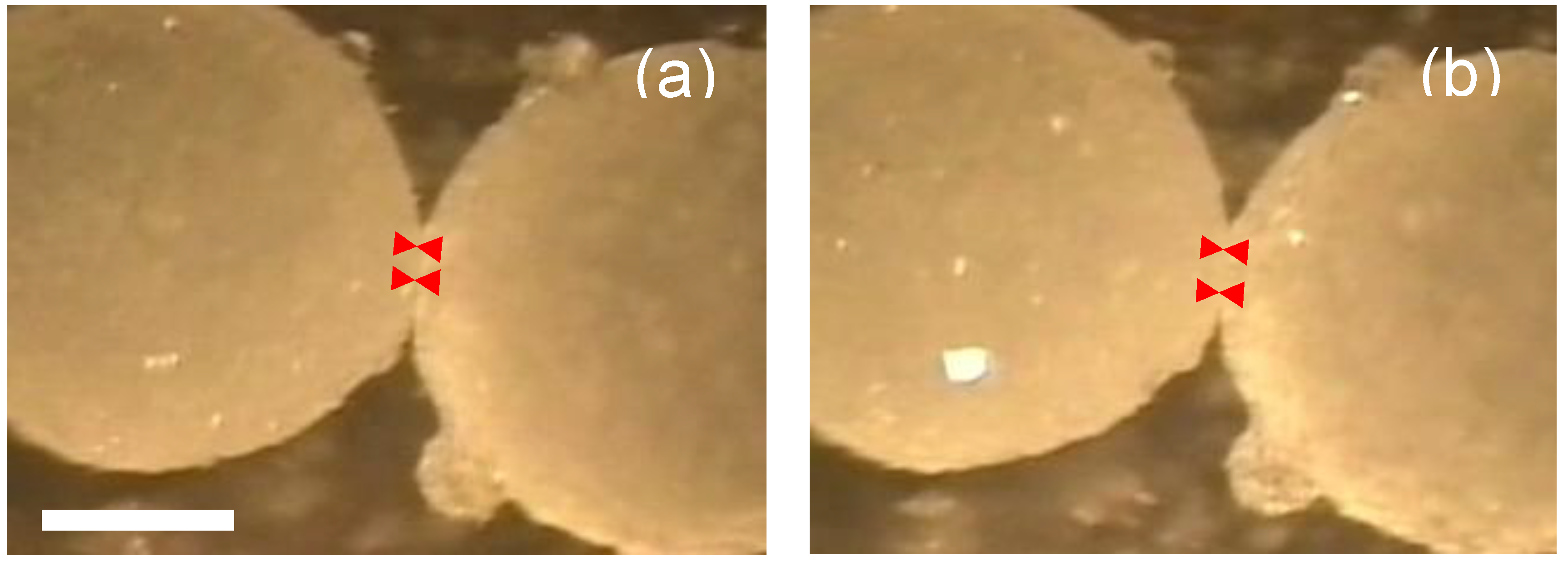
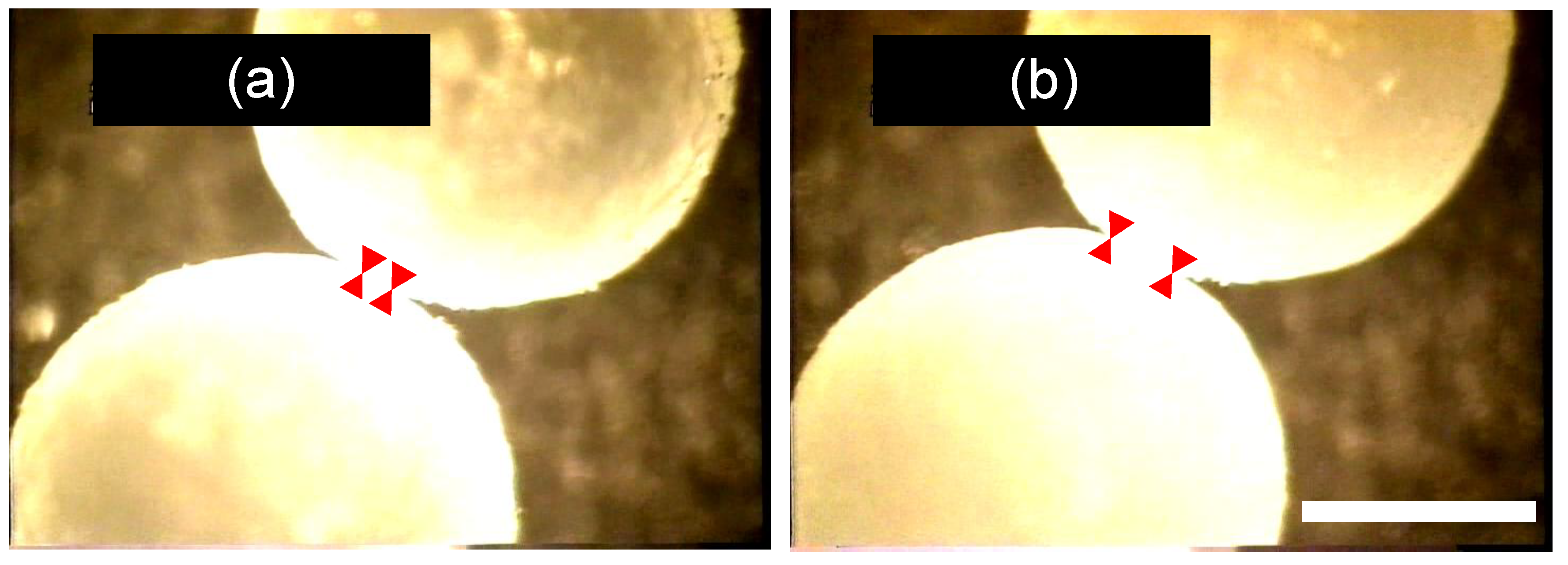
The microscopic observations of THF hydrate particles indicated the sintering occurred at similar conditions for ice particles (263.2 K and 0.1 MPa,
Figure 2); however, the growth rate of the necks was lower than that for ice. We confirmed that the sintering part was not ice but THF hydrate by increasing the temperature above 273.2 K after the completion of each experiment.
Figure 1.
Sintering of ice particles at 263.1 K: (a) initial condition and (b) 6 h after contact. Scale bar indicates 1 mm. Red allow heads indicate the edges of sintering neck.
Figure 1.
Sintering of ice particles at 263.1 K: (a) initial condition and (b) 6 h after contact. Scale bar indicates 1 mm. Red allow heads indicate the edges of sintering neck.
Figure 2.
Sintering of THF hydrate particles at 263.2 K: (a) 10 min after contact and (b) 6 h after contact. Scale bar indicates 1 mm. Red allow heads indicate the edges of sintering neck.
Figure 2.
Sintering of THF hydrate particles at 263.2 K: (a) 10 min after contact and (b) 6 h after contact. Scale bar indicates 1 mm. Red allow heads indicate the edges of sintering neck.
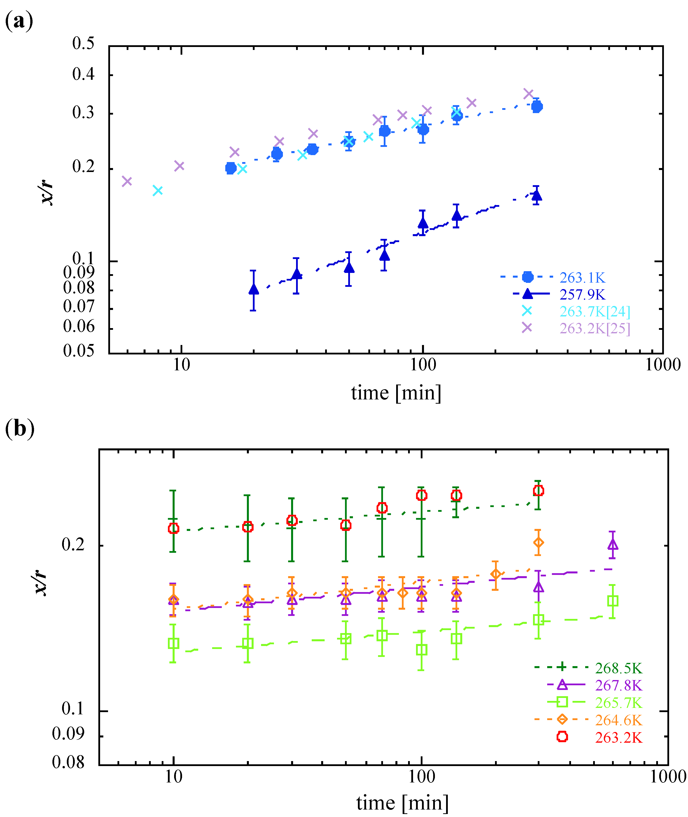
To compare the sintering rates quantitatively, we measured the size ratio between the neck radius
x and the particle radius
r as a function of time. The sintering rate is usually expressed as:
where
t is time, C is a parameter which captures material and geometric constants, and
p and
q are numerical constants depending on the working mechanism [
21,
23]. The logarithmic relationship of
x/r with
t for the results obtained in the present study (
Figure 3) indicates that both the sintering of ice and THF hydrate particles follow Equation (1).
Figure 3a shows that the sintering rates of ice particles coincided well with the rates obtained in previous studies [
24,
25]. These agreements validate our experimental procedures. Previous studies [
23] and the present observations indicate that the main rate-determining process of ice-particle sintering under the present experimental conditions was H
2O molecule transportation through the vapor phase.
Figure 3.
Relative neck growth
x/
r (
x: neck radius,
r: average particle radius)
versus time
t for (a) ice particles and (b) THF hydrate particles. The data from [
25] is drawn as the average of three experiments at 263.2 K.
Figure 3.
Relative neck growth
x/
r (
x: neck radius,
r: average particle radius)
versus time
t for (a) ice particles and (b) THF hydrate particles. The data from [
25] is drawn as the average of three experiments at 263.2 K.
The sintering rates for THF hydrates were less than those for ice particles (
Figure 3b). The time constant
q−1 was approximately 0.055 for THF hydrates and 0.16 for ice particles at 263 K (see
Table 1). Although the surfaces of THF hydrate particles were smoothed during sintering (it can be seen that the reflection of the light increased in
Figure 2b), the values of
q−1 for THF hydrates were much smaller than expected for the vapor transportation mechanism [
21]. If we assume that the rate-determining process for THF hydrate particles is the vapor transportation mechanism under the present experimental conditions, we consider that the lower sintering rate for THF hydrates than for ice would result from a lack of guest molecules being supplied for the clathrate hydrate formation at the neck because it requires both guest and host molecules.
To investigate the sintering process mentioned above, we carried out similar experiments under almost saturation conditions with THF vapor in the reaction cell. The THF hydrate particles were set in the sample cell, which was in turn immersed in THF solution. The microscopic images of THF particles are shown in
Figure 4 and their sintering rates in
Figure 5. The figures show the sintering rates that were obviously higher than those of previous experiments under the normal vapor conditions (
Figure 2 and
Figure 3b) at the same temperatures.
Figure 4.
Sintering of THF hydrate particles under saturation condition in vapor at 262.2 K: (a) 10 min after contact and (b) 6 h after contact. Scale bar indicates 1 mm. Red allow heads indicate the edges of sintering neck.
Figure 4.
Sintering of THF hydrate particles under saturation condition in vapor at 262.2 K: (a) 10 min after contact and (b) 6 h after contact. Scale bar indicates 1 mm. Red allow heads indicate the edges of sintering neck.
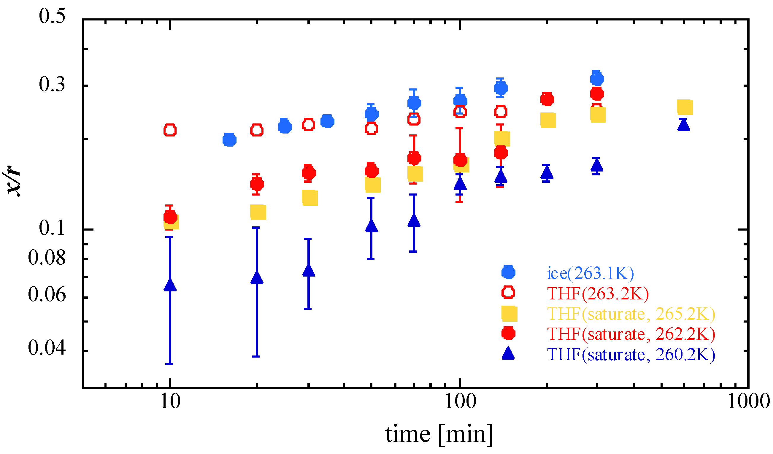
Figure 5.
Relative neck growth x/r (x: neck radius, r: average particle radius) versus time t for THF hydrate particles when the atmosphere was saturated with THF vapor. For comparison, experiments for ice at 263.1 K (right blue solid circles) and for THF hydrate under the normal vapor condition at 263.2 K (red open circles) are also plotted.
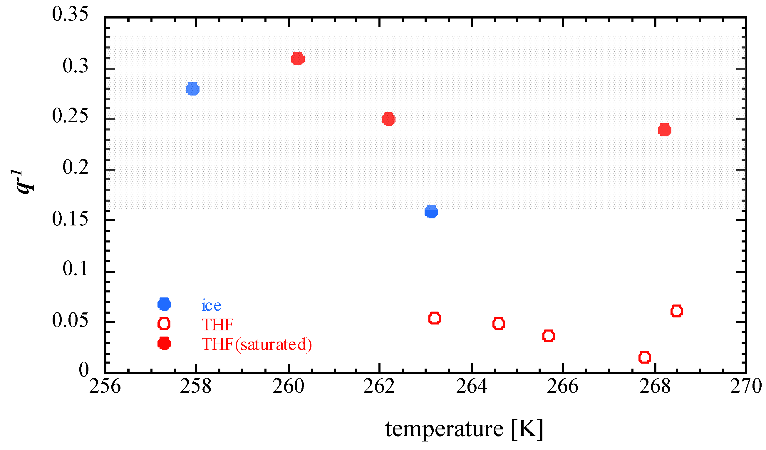
The time constant of the sintering rate of THF hydrates under saturation conditions was approximately 0.25 (
Figure 6), within the temperature range of the present study. This time constant was approximately five times that for THF hydrates under the normal vapor condition and almost of the same order as that for ice particles at similar temperature. Blackfold [
21] summarized previous works discussing about the relation between the value of the time constant and the dominant mass transport mechanisms. Although the estimation of the time constant related to each suggested mechanism has not been agreed upon yet, the estimated value for both ice and THF hydrate under saturated conditions are belong to the range of the time constants suggested previously [
21] (shown by hatched area in
Figure 6). Therefore, it is considered that the sintering rate of THF hydrates was mainly controlled by the supplementing of guest molecules from the vapor phase accompanied with the host water molecule transportation.
Figure 6.
Temperature dependence of
q−1 for ice (blue solid circle) and THF hydrates (normal vapor condition: red open circle, THF saturated vapor conditions: red solid circle). The hatched area indicates the expected
q−1 value for the vapor transportation mechanism [
21].
Figure 6.
Temperature dependence of
q−1 for ice (blue solid circle) and THF hydrates (normal vapor condition: red open circle, THF saturated vapor conditions: red solid circle). The hatched area indicates the expected
q−1 value for the vapor transportation mechanism [
21].
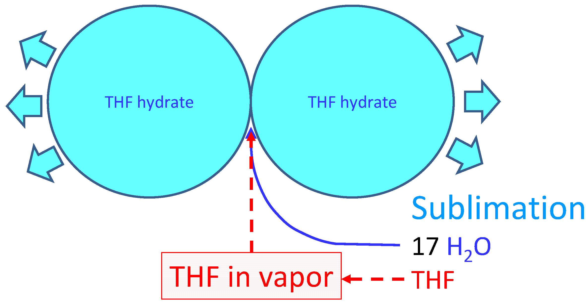
Thus the supposed process of THF hydrate sintering is illustrated in
Figure 7. The early stage of sintering is the molecular transportation to the contact point mainly by surface diffusion [
23]. However, we could not observe this process owing to low spatial resolution of the experimental setup. In the following process under the storage condition, the THF hydrate sublimated when the vapor was undersaturated with H
2O and THF.
Figure 7.
Schematic illustration of sintering of THF hydrate particles.
Figure 7.
Schematic illustration of sintering of THF hydrate particles.
The sublimation was observed under a microscope by the gradual increase in reflection from the surface of particles. Since the molecular composition of the original THF solution was THF:H2O = 1:17, and the formed THF hydrates were usually polycrystals with some composition variations heterogeneously, the molecules emitted into the surrounding atmosphere are considered to be H2O rich (the THF concentration would be less than 5.5 mol%). The H2O molecules moved to the sintering site under the concentration gradient according to the Gibbs-Thomson effect. If THF molecules were saturated in the vapor phase under the storage condition, they would also be transferred easily to the sintering site to form THF hydrate. This would be the case in the sintering experiment of THF hydrates in saturated THF vapor. Under this condition, THF hydrate sintered as quickly as ice. However, the experiments without THF solution around the particles had much lower sintering rates. This is explained by the lack of THF molecules to form THF hydrate at the sintering site. Although we do not have enough data of the saturated vapor pressure of THF at temperatures below 273.2 K in the presence of THF hydrate, the results obtained in the present study indicate that THF molecules emitted only by sublimation were insufficient to grow the sintering neck.
On the basis of this THF hydrate sintering process, we can consider the storage and transportation processes of NGHs. Although the sintering rate is lower than that of ice, gas hydrates also undergo sintering when they are stored for a significant period at temperatures below the melting point of ice. Since the sintering of gas hydrate particles requires the supplement of both host H
2O and guest gas molecules, the sintering of gas hydrates was controlled by the vapor concentration of both molecules. In other words, the rate of sintering depends on the vapor pressure of guest or host molecules. However, if the hydrate particles are coated by ice to emphasize the self-preservation effect, such as in the case of hydrate pellets [
25], the sintering process would be similar to that of ice because sintering occurs mainly at the surface of the sample.
3. Experimental Section
We prepared a spherical THF hydrate to observe sintering under a microscope. A droplet of the THF solution prepared from 99.5% THF (Wako Pure Chemical Industries, Ltd.) and de-ionized distilled water with a stoichiometric concentration (THF:H
2O = 1:17 in mole fraction) was rapidly frozen in liquid nitrogen. The quench process made the sample a polycrystal containing very fine grains with random crystal orientation. Therefore, we eliminated the effect of crystal orientation on the sintering rate reported by Hobbs and Mason [
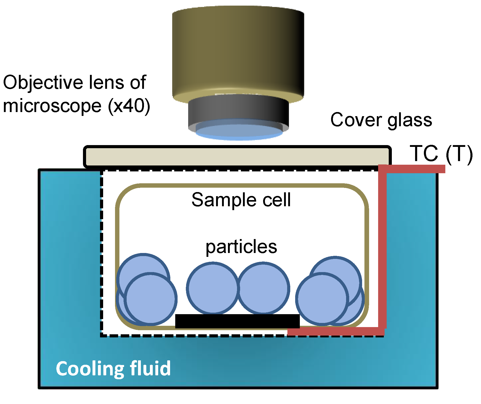
26]. Then the particles annealed at 274–275 K to make a small spherical particle of THF hydrate (2–3 mm in diameter). At the same time, the very fine ice grains would be consumed for the recrystallization of THF hydrate polycrystal. THF hydrate particles were stored in a temperature-controlled cell placed on the stage of a microscope (Nikon FMZ-10) equipped with a CCD camera (Olympus CS230B) and a time-lapse S-VHS video recorder (Victor SR-S990). The lighting of the sample was Nikon cold-fiber optics light system to eliminate the temperature increase during the experiment. Two particles were selected to observe the sintering in the experiment, and remaining other particles worked for maintaining a stable atmosphere in the cell. A schematic diagram of the experimental setup is shown in
Figure 8. The temperature of the sample cell was controlled at above 260 K within ±0.2 K.
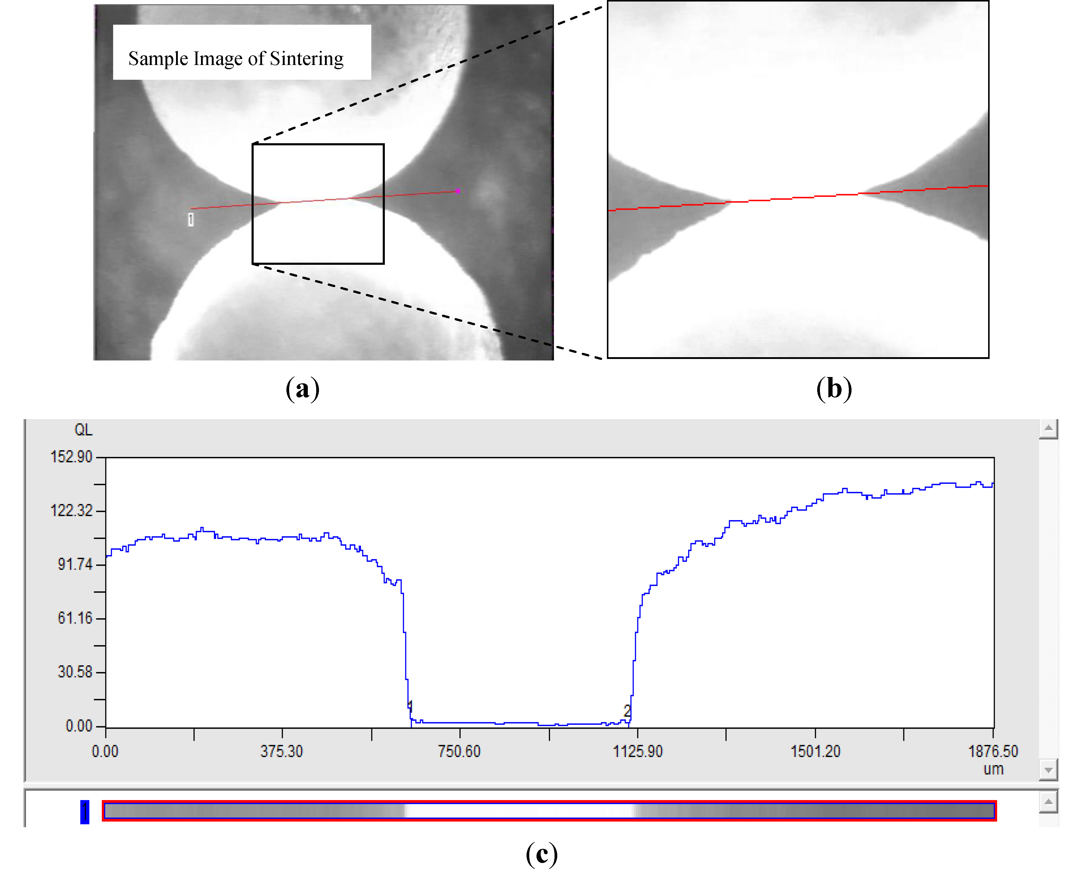
The video images were analyzed using an image analyzing software (Fuji Photo Film Co., Ltd. MultiGauge) to measure the sizes of particles and the sintering neck. The spatial resolution was approximately 5 m for the present experimental setup. The uncertainty for measuring the neck size x was severe in early stage (less than one hour) because the image of the contact point was fuzzy, especially for some particles having rough surface near the contact point. The estimated uncertainties were drawn in x/r-time diagrams with error bars. The irregularity of ice particle size was ignored in the error estimation due to its small contribution to the uncertainty of x/r. One example of measurements of x is shown in the Electronic Supplementary Information.
Figure 8.
Schematic illustration of experimental setup.
Figure 8.
Schematic illustration of experimental setup.
To validate the experimental procedure, the same experiments were carried out on pure ice particles. For experiments under the THF saturation condition, the particle samples were placed on the stage in the sample cell (black rectangle in
Figure 8), which was immersed in a small amount of THF solution at the bottom of the cell instead of extra particles. The sample sizes used in the present study are summarized in
Table 1.
Table 1.
Experimental conditions and rate constants of sintering. r1 and r2 are the radii of the two particles used in the sintering experiment.
Table 1.
Experimental conditions and rate constants of sintering. r1 and r2 are the radii of the two particles used in the sintering experiment.
| | r1 (mm) | r2 (mm) | q−1 |
|---|
| Ice (263.1 K) | 1.14 | 1.15 | 0.16 |
| Ice (257.9 K) | 0.99 | 1.13 | 0.28 |
| THF (268.5 K) | 1.19 | 1.20 | 0.061 |
| THF (267.8 K) | 1.09 | 1.10 | 0.015 |
| THF (265.7 K) | 1.19 | 1.25 | 0.037 |
| THF (264.6 K) | 0.92 | 0.97 | 0.049 |
| THF (263.2 K) | 0.79 | 0.82 | 0.055 |
| THF (saturated, 268.2 K) | 1.32 | 1.19 | 0.24 |
| THF (saturated, 262.2 K) | 1.06 | 1.08 | 0.25 |
| THF (saturated, 260.2 K) | 1.07 | 1.18 | 0.31 |


