


Abstract
Traditional overburden bed-separation grouting technology often leads to issues of grout leakage and insufficient control of surface subsidence, primarily due to its poor adaptability to specific mining conditions such as isolated coal pillar recovery, the development of stratigraphic faults and fractures, or the absence of clearly identifiable key strata. To address these limitations, this study proposes an innovative multi-bed-separation precise grouting technology. The formation mechanism of multi-bed separations is analyzed, their development positions are determined, and an engineering solution for controlling surface subsidence after multi-bed-separation grouting is proposed. Key technical parameters, including grouting pressure, stability of grout-isolating layers, grouting space volume, and grout amount, are theoretically analyzed. A “three-step” precise grouting process—consisting of separation detection and verification, fracture curtain sealing, and precise grouting for subsidence reduction—was developed and applied in the 12030 isolated coal pillar panel of Xinyi Coal Mine. A total of 504,500 tons of fly ash (including cement) was grouted, of which 398,600 tons was used for precise grouting in multi-bed separations of overburden. This approach recovered 1,364,400 tons of coal resources beneath village buildings, with a grouting–extraction ratio (volume ratio) of 0.53. The technology demonstrates clear advantages: no grout leakage occurred during the process, the surface subsidence reduction rate reached approximately 75.81%, and building damage was controlled within Grade I. The results demonstrate that this technology has a significant effect on subsidence reduction and damage control, enabling safe and green mining of coal resources beneath villages under special geological and mining conditions.
1. Introduction
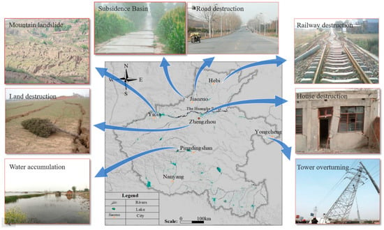
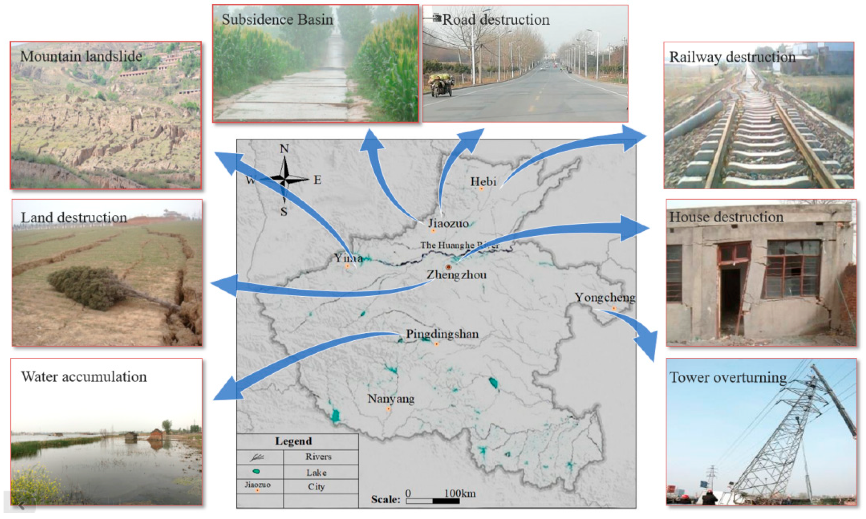
Large-scale coal mining induces overburden damage and bed-separation development, which propagate to the surface as subsidence and fractures, directly damaging surface structures, water bodies, and railways [1,2,3]. Additionally, coal mining and utilization inevitably generate solid wastes such as gangue, fly ash, and slag, which not only occupy land resources but also pose severe threats to the ecological environment [4,5]. Against the backdrop of global carbon emission reduction and ecological protection, the coal industry must pursue a path of green and sustainable development [6,7]. Henan Province, a core region in central China, is both a populous province and one of China’s major coal-producing regions [8]. Surface subsidence, village house damage, and land destruction caused by coal mining are particularly prominent, as shown in Figure 1.
Figure 1.
Damage caused by coal mining.
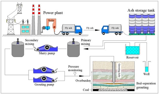
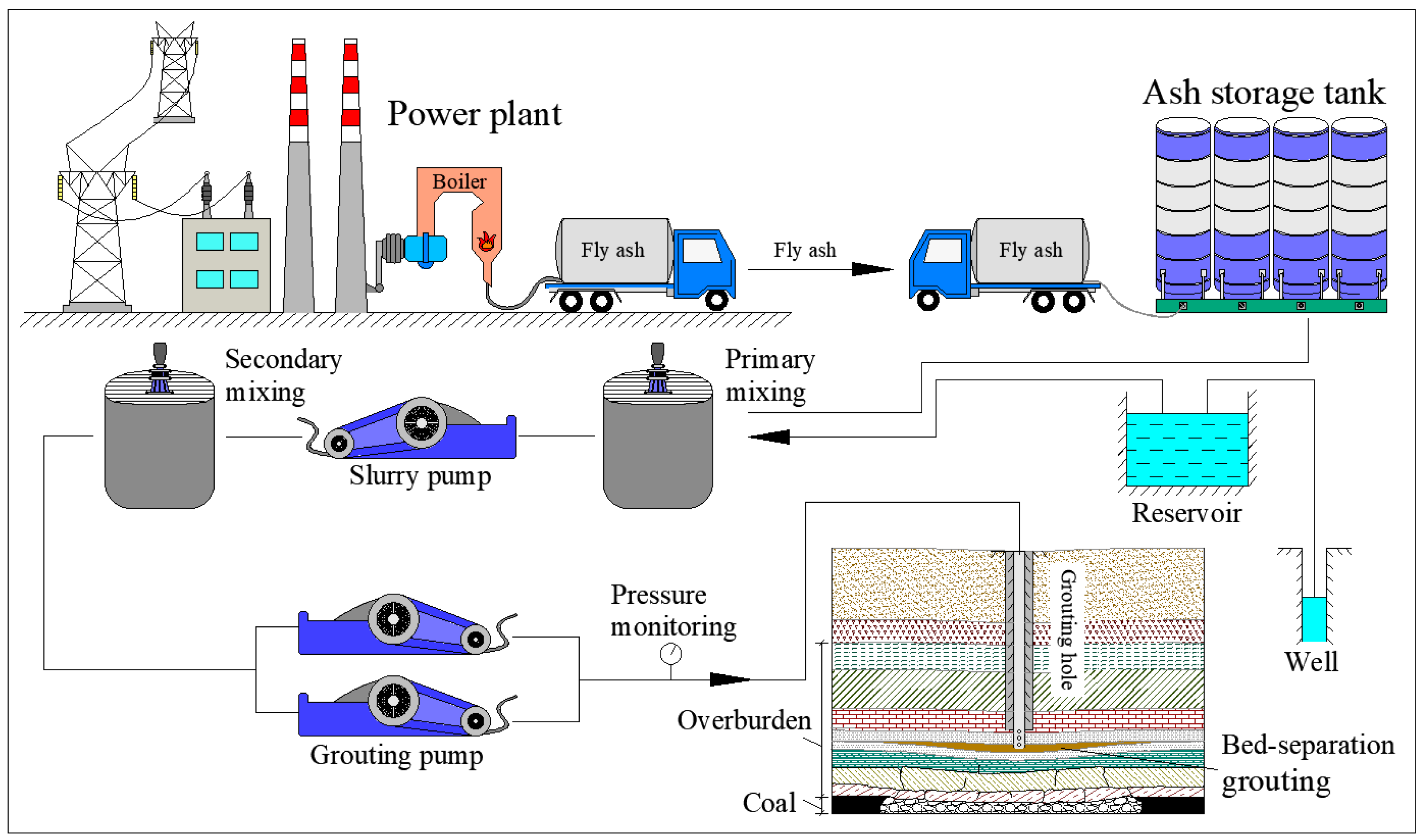
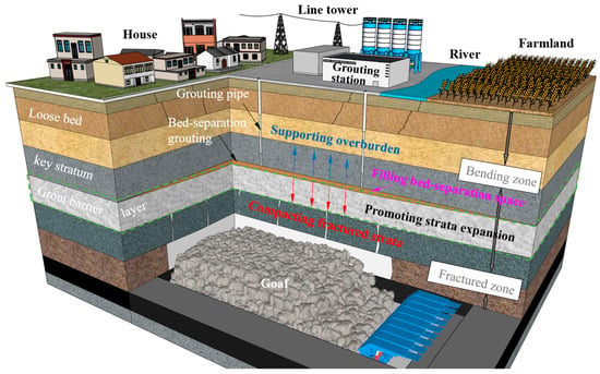
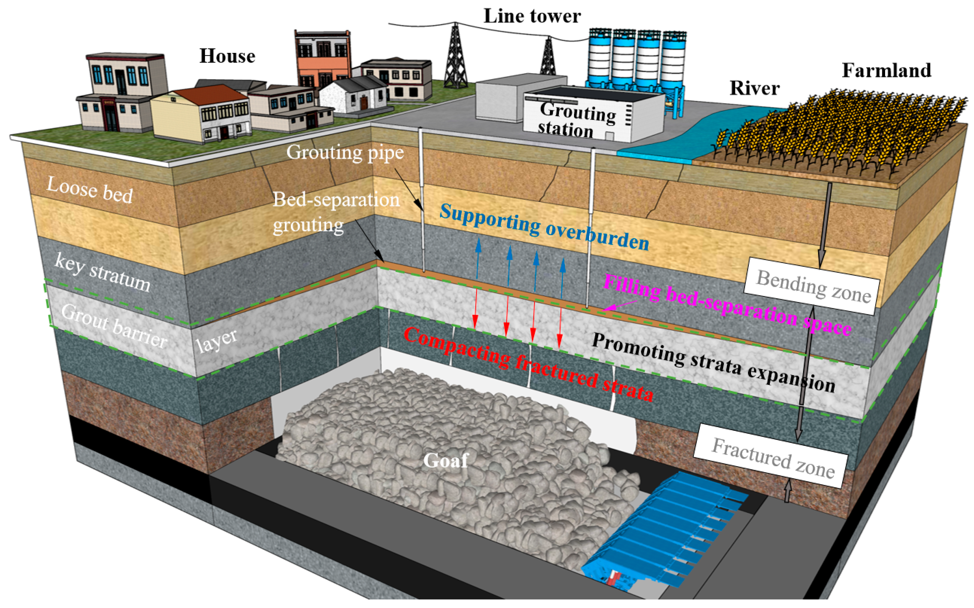
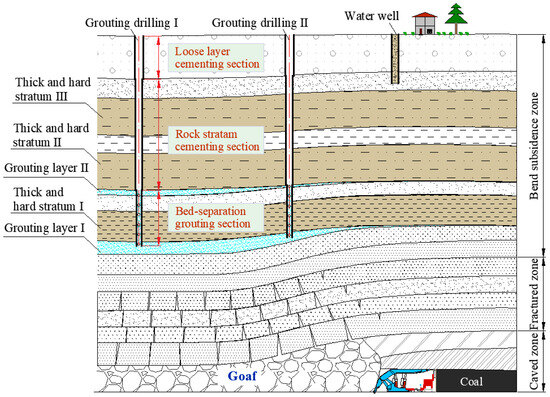
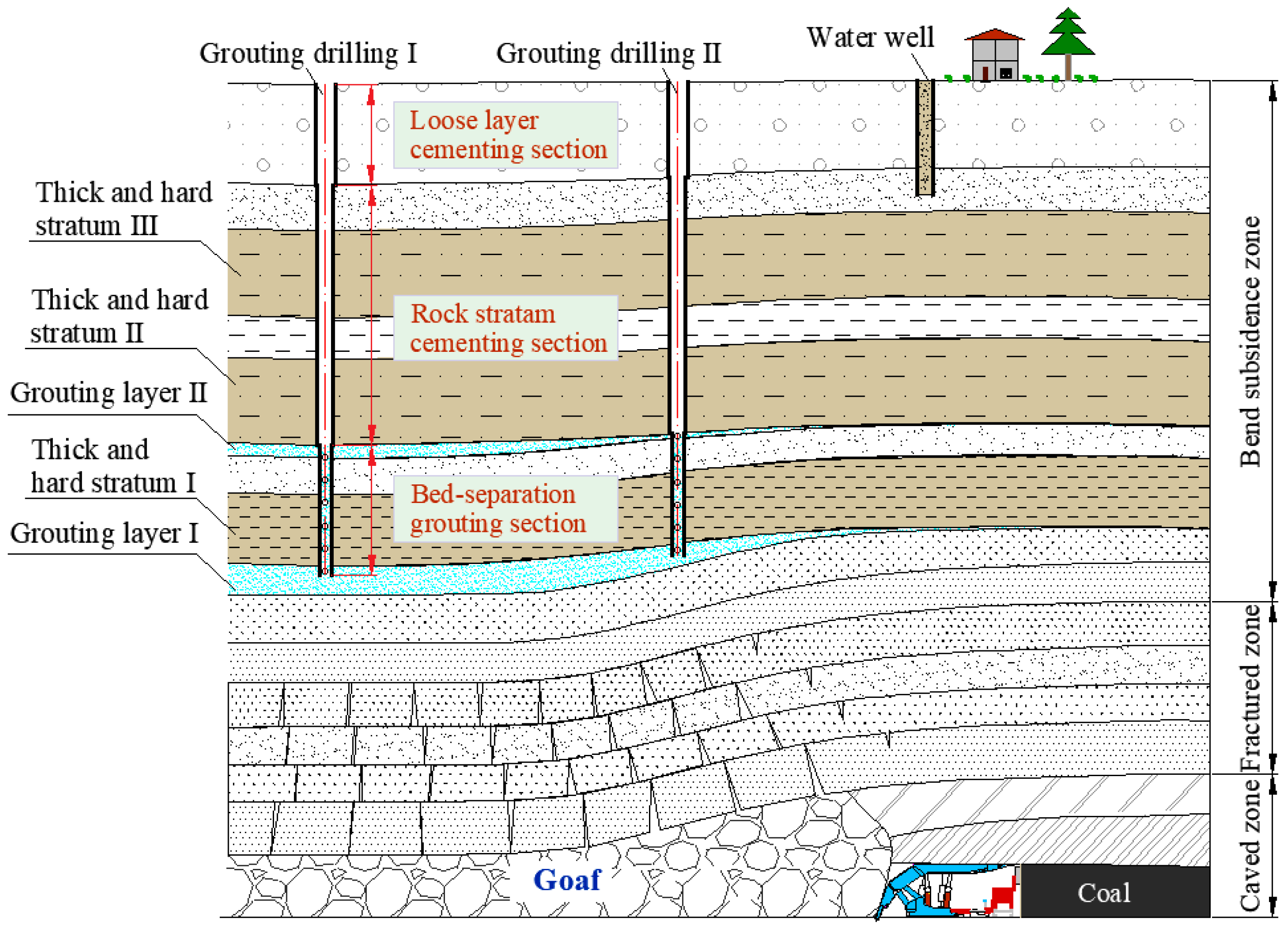
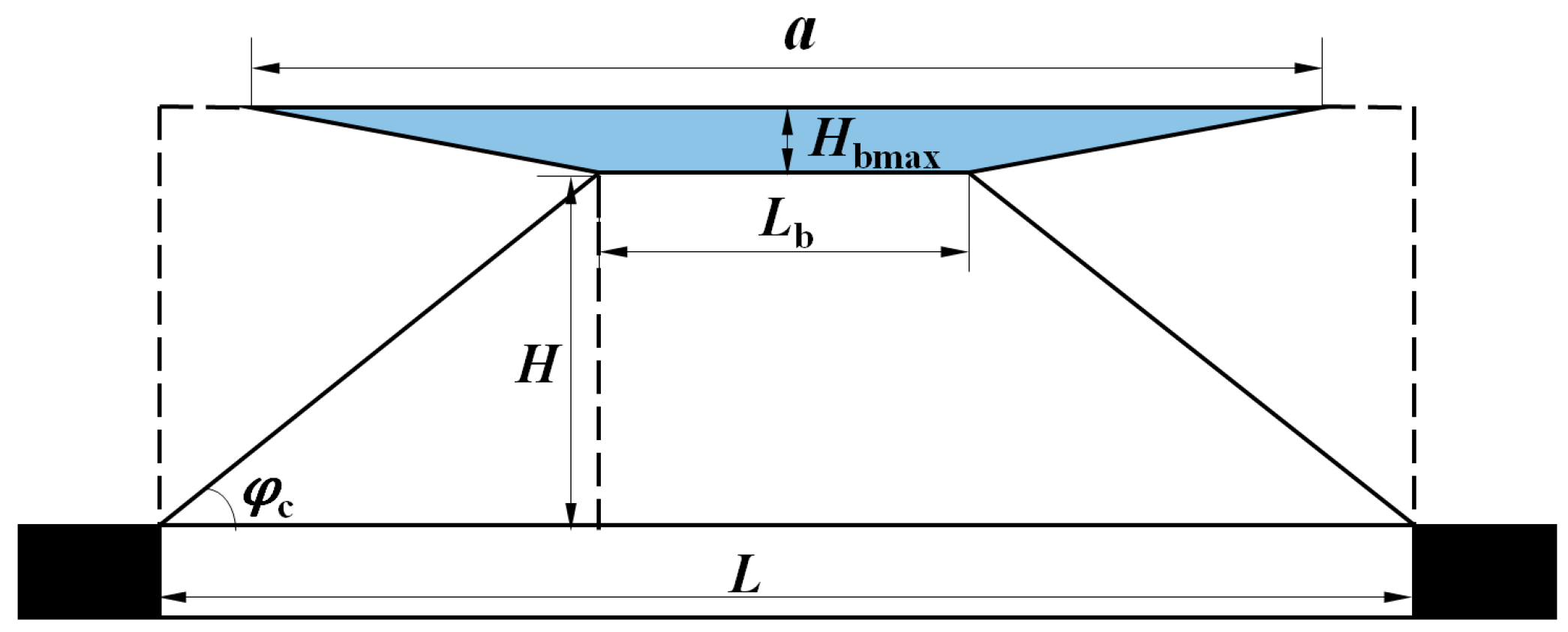
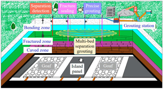
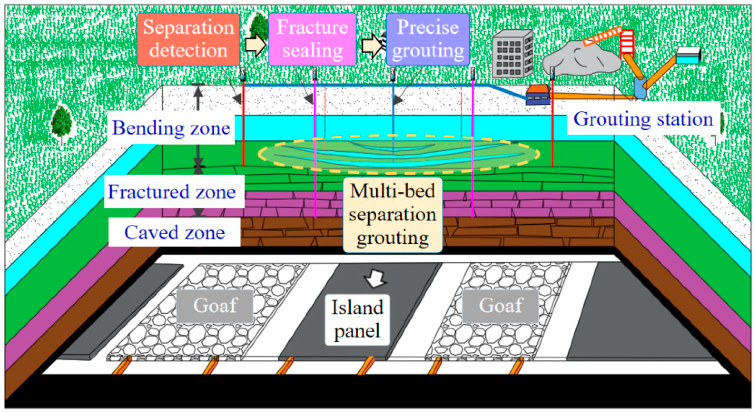
Most mining areas in the province are in the middle and late stages of mining, facing challenges such as coal resources under surface structures and recovery of isolated coal pillars [9,10]. Overburden bed-separation grouting, a key technology in the green mining system, provides an effective approach to address these issues. The workflow of overburden bed-separation grouting is shown in Figure 2.
Figure 2.
The workflow of overburden bed-separation grouting.
Based on the characteristics of layered overburden movement, this technology involves grouting filling materials into separation zones through boreholes to support overburden, suppress rock mass damage above separations, and thereby reduce surface deformation [11,12]. Its subsidence reduction and damage control mechanisms mainly include the following [13,14,15]: (1) filling materials occupy part of the separation space, reducing the transfer of separation voids to the surface; (2) the supporting effect of fillings reduces the bending deflection of upper strata; (3) fillings squeeze lower strata, compacting separation spaces and fractures; (4) grout may induce expansion of swelling rock layers when in contact. Subsidence reduction mechanisms of this technology are shown in Figure 3.
Figure 3.
Subsidence reduction mechanisms of overburden bed-separation grouting.
A typical advantage of this technology is that surface grouting and underground mining operations do not interfere with each other [12]. Compared with strip mining, it overcomes the problems of low mining efficiency and severe coal resource waste [9,16]; compared with underground goaf filling, it solves issues of complex processes, high costs, and low efficiency [17]. In recent years, scholars have conducted multi-dimensional research on overburden bed-separation grouting in terms of theoretical models, grouting technology optimization, and engineering applications.
In theoretical model research, field borehole investigations revealed that more than 90% of the total fill was concentrated in the main injection section of the overburden, which had a thickness of 4.8–18.4 m. This section was situated between the bottom of the injection borehole and the key stratum directly above it [18]. The elastic foundation beam model demonstrates that grout-isolating layers maintain stability when the dimensionless ratio of deflection to void height (Δw/h) ≤ 0.63 [19]. A correlation between grout diffusion radius and grouting pressure in overburden was established, and compared to classical models (Maag and cylindrical formulas), the goodness of fit improved by 34–39%, offering a valuable reference for diffusion studies and grouting design [20]. Aimed at the development of water-conducting fractures in overburden and the prevention of water inrush risk during coal mining under water bodies, a quantitative assessment model for overburden failure and water inrush risk was developed. Combined with the practice of directional grouting engineering, the control mechanism of the water-conducting fracture zone under complex geological conditions was revealed [21]. Four overburden structure models under single and multiple key strata were constructed to systematically study the dynamic evolution patterns of the bed-separation zone, revealing results contrary to the general rule that “bed-separation clearance increases with mining height” [22].
In grouting technology optimization, a method for analyzing the effect of overburden bed-separation grouting was proposed, and the relationship between six representative surface subsidence reduction rates and grouting–extraction ratio was studied, which was verified by the established Gompertz model [23]. Similarity simulations confirm an optimal grouting pressure of 0.6–0.8 times the formation fracture pressure, increasing fill volume by 40–60% [24]. The influence of panel size, mining height, coal seam inclination angle, mining speed, and grouting parameters on the effect of overburden bed-separation grouting was studied by establishing a model, and the mining and grouting parameters were optimized [25]. The CDEM simulation reveals the distribution characteristics of multi-bed separations in the overburden and clarifies the optimal timing for bed-separation grouting [26]. Grouting the bed-separation space during the mining process can effectively control the sliding of the high-position main key stratum and prevent strong dynamic loading impacts, resulting in a 59% reduction in peak abutment pressure [27].
In engineering applications, a test in Liudian Coal Mine showed a maximum surface subsidence of 0.298 m, and building damage controlled within Grade I [28]. Overlying strata isolation grouting also reduces goaf gas emission by 46% [29]. Engineering practice in the Huainan mining area demonstrates that, even in overburden lacking thick–hard strata for large-scale bed separations, multi-layer grouting through increasing boreholes effectively forms multi-level diffusion fills, controlling surface subsidence and structure damage (within Level I) [30]. In the mine with bed-separation grouting, the characteristic solute aluminum from the grout precipitation water migrates locally into the aquifer above the grouted separation layer. However, its impact is confined within the working face area (approximately 500 m in length) and gradually dissipates after the project concludes [31]. UDEC numerical simulation of Vietnam’s Nui Beo Coal Mine determined a 63 m overburden displacement zone and 160 m surface impact range (52° caving angle) from 31104 panel mining, consistent with actual operations and applicable to safety and impact assessment [32]. The technology of overburden grouting with directional drilling under buildings was proposed, and key technical parameters such as optimal spacing and layout of directional drilling were determined by establishing a trajectory expansion model of directional drilling. The engineering application shows that the maximum surface settlement is 34 mm, and the building is within the Grade I damage range [12]. Overburden bed-separation grouting can significantly control surface subsidence, reducing the maximum subsidence value by 66.67%, lowering the average subsidence value at each measuring point on the main cross-section by 78.92%, and decreasing the subsidence-affected area by 34.68% [33].
Despite these advances, traditional overburden bed-separation grouting has certain limitations, poor adaptability to mining geological conditions (e.g., island coal pillar recovery, lacking clearly identifiable key strata, etc.), and a high susceptibility to grout loss under conditions like isolated pillar mining or in strata with significant fault/fracture development [23,28,34]. Issues like coordinated grouting of multi-layer separations and parameter optimization require further exploration.
Therefore, considering the complex geological conditions of isolated coal pillar panels (such as surrounding goafs and severe overburden damage) and the high demands of surface subsidence control, this study develops an innovative technology termed precise grouting in multi-bed separations of overburden (PG-MBSO). The mechanism and development positions of multi-bed separations of overburden (MBSO) are analyzed, key technical parameters of the PG-MBSO are studied, a “three-step” precise grouting process for isolated coal pillar panel mining is proposed, and an engineering application is conducted. The characteristics, advantages, grouting pressure control, and subsidence reduction effects of this technology are discussed, providing a new solution for recovering coal resources under structures in special geological conditions.
2. Geological and Mining Conditions
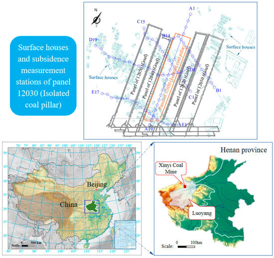
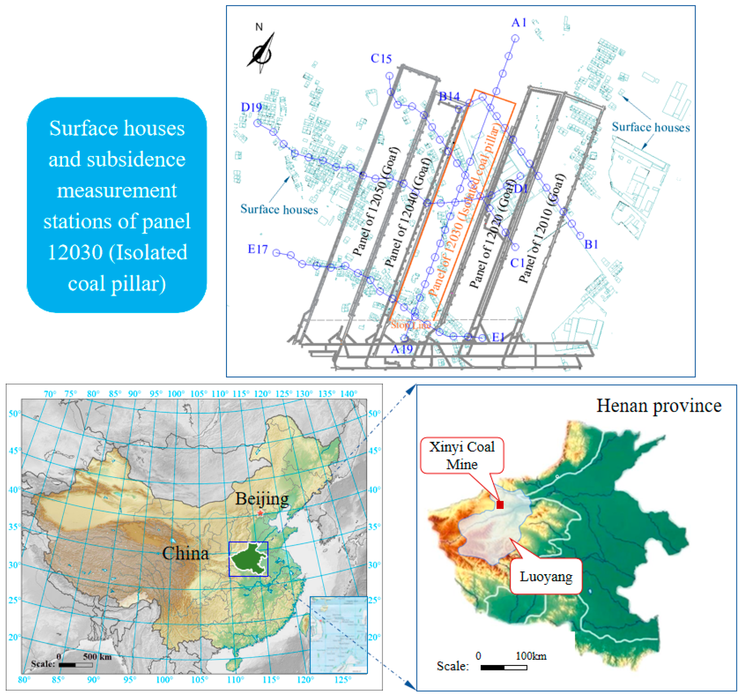
Xinyi Coal Mine is located in the northern part of Xinan Coalfield, Luoyang City, Henan Province, with geographical coordinates ranging from 112°04′18″ to 112°11′58″ E and 34°44′48″ to 34°49′12″ N. The northern and southern parts of the 12030 panel are protective coal pillars, the western part is the goaf of the 12040 panel (mined out in June 2014), and the eastern part is the goaf of the 12020 panel (mined out in December 2015). Due to mining on both sides, the overburden and surface of the 12030 panel have varying degrees of damage. The 12030 panel has an inclined length of 810–870.3 m and a strike length of 158 m, with an average coal thickness of 5.0 m and an average dip angle of 5°. It adopts the inclined longwall fully mechanized top-coal caving mining method. The panel is situated at a burial depth of approximately 759.7 m. Due to the surrounding goaf of the panel, the water inflow during the panel mining period was very small under the effect of drainage and pressure reduction in the early stage, which had little impact on production.
The surface area affected by the panel mining includes more than 800 households in three villages: Zhaogou, Xibai, and Yingli. Direct mining without protective measures will inevitably cause severe damage to the houses, requiring relocation and reconstruction, but there are difficulties such as site selection and high costs. The location of the 12030 panel, surrounding mining activities, surface building distribution, and observation station layout are shown in Figure 4.
Figure 4.
Mining activities around panel 12030 and distribution of surface buildings and observation station.
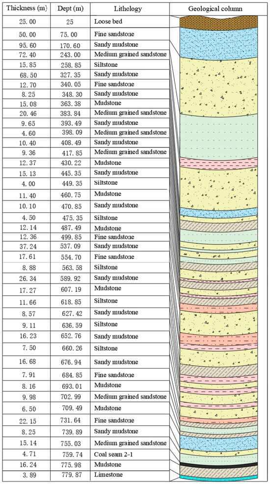
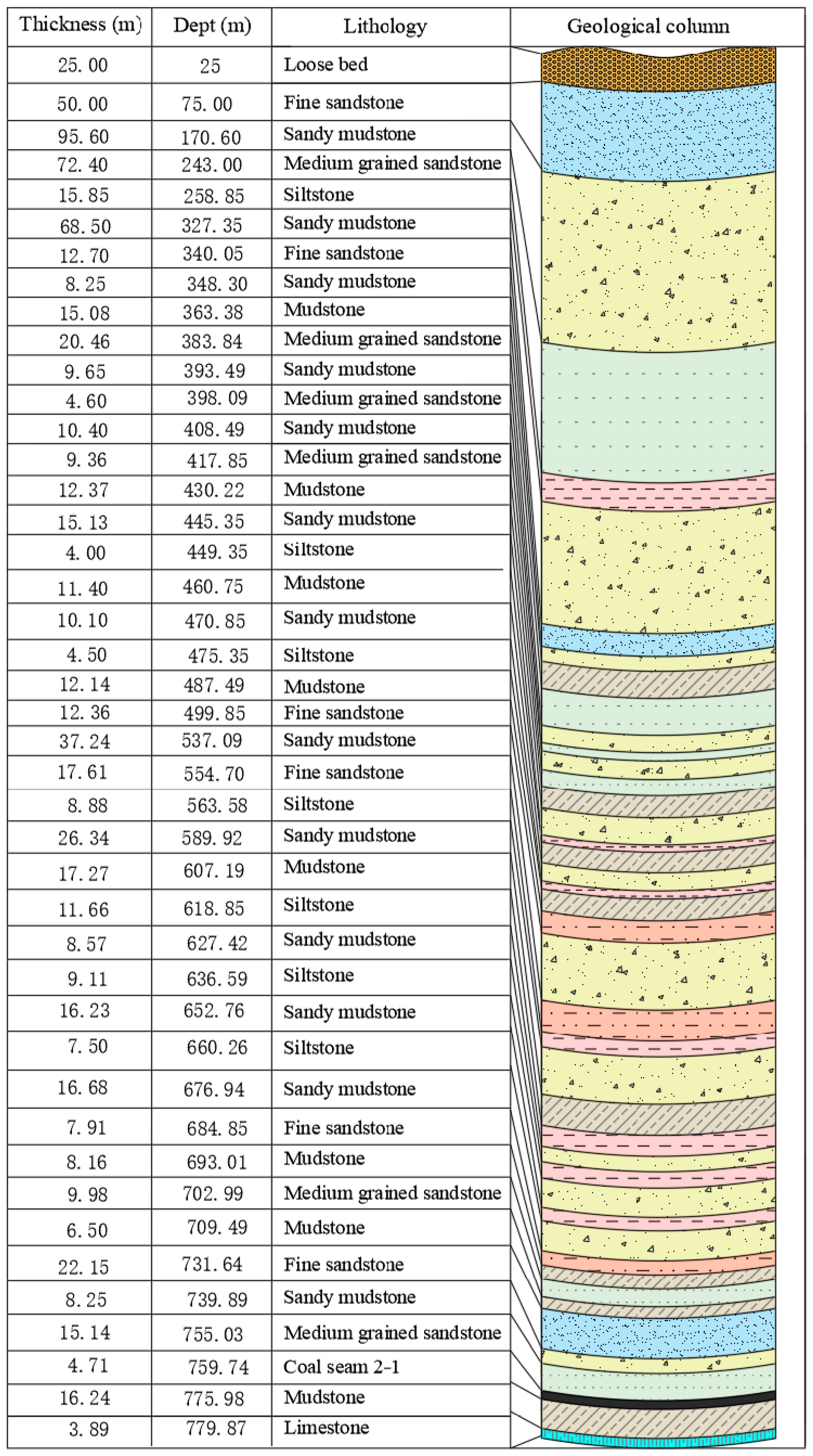
The mined coal seam is the No. 2-1 coal of the Shanxi Formation. The roof of the coal seam locally has a carbonaceous mudstone pseudo-roof, with the direct roof being sandstone or sandy mudstone, the main roof being medium-grained sandstone, the direct floor being siltstone, and the main floor being siliceous mudstone. The stratigraphic column is shown in Figure 5.
Figure 5.
Stratigraphic column chart of 12030 panel.
3. Technology of the PG-MBSO
3.1. Model of the PG-MBSO
- (1)
- Formation mechanism of the MBSO
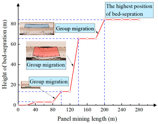
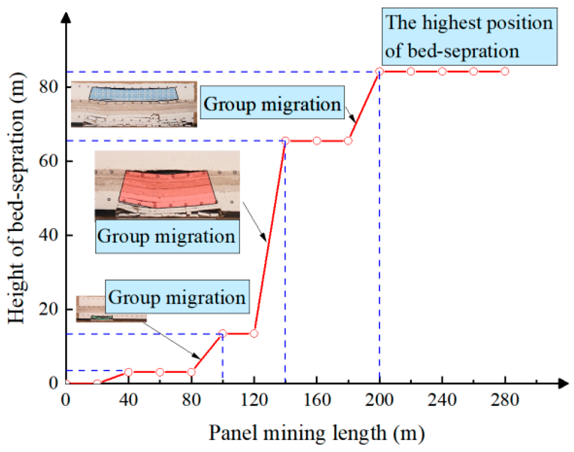
Overburden above coal seams is mainly composed of sedimentary rocks, showing layered distribution characteristics with varying thicknesses and mechanical properties. Relevant studies have shown that some thick and hard strata in overburden play a major role in rock movement; thus, mining-induced overburden exhibits group migration characteristics. When high-position thick and hard strata and low-position strata undergo uncoordinated deformation and meet the conditions of tensile stress, stiffness, and mining size, separations will appear below the thick and hard strata. The development characteristics of separations vary under different mining geological conditions but have similarities: the development height of separations increases stepwise with the advanced distance of the working face, as shown in Figure 6.
Figure 6.
Development characteristics of overlying strata bed separation.
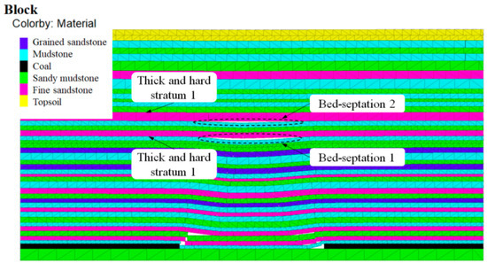
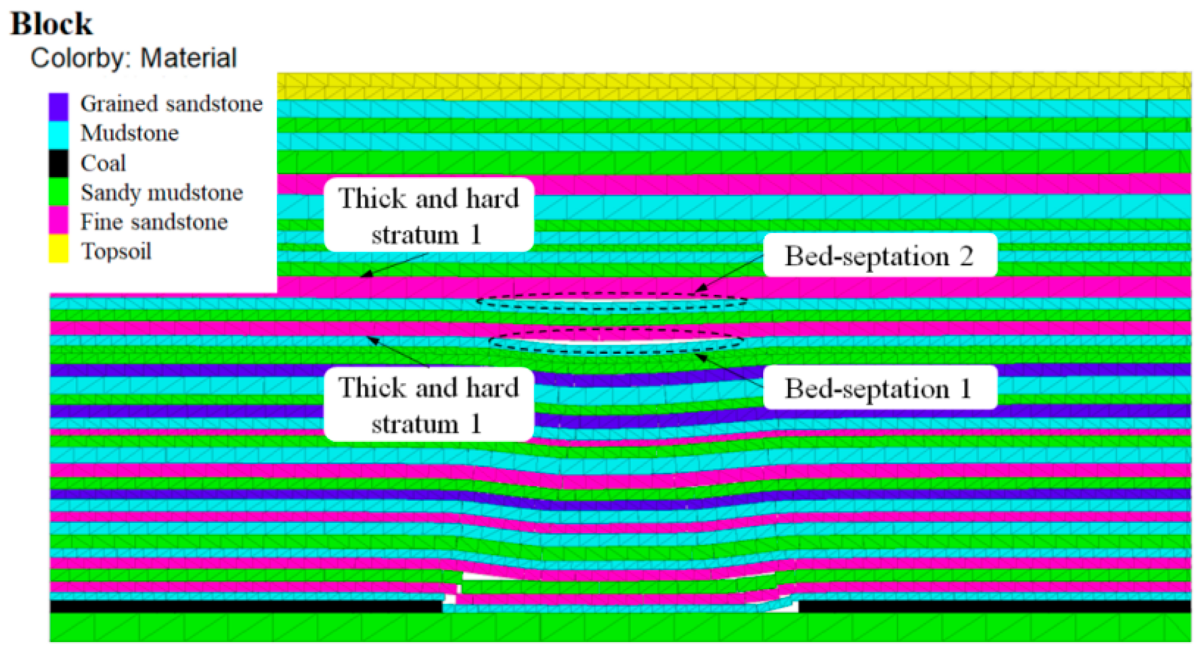
Figure 7 illustrates the results of a numerical simulation of overburden bed-separation development during coal seam mining. It shows that under conditions where the overburden exhibits a high soft–hard rock alternation ratio and small thickness of each stratum, which promote large overall coordinated deformation and rapid development–closure transfer of separations, separation spaces simultaneously appear below multiple relatively thick and hard strata. These separation spaces gradually close and propagate upward with the advancement of the working face, eventually forming a surface subsidence basin.
Figure 7.
Development of the MBSO.
- (2)
- Development positions of the MBSO
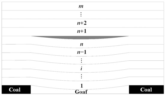
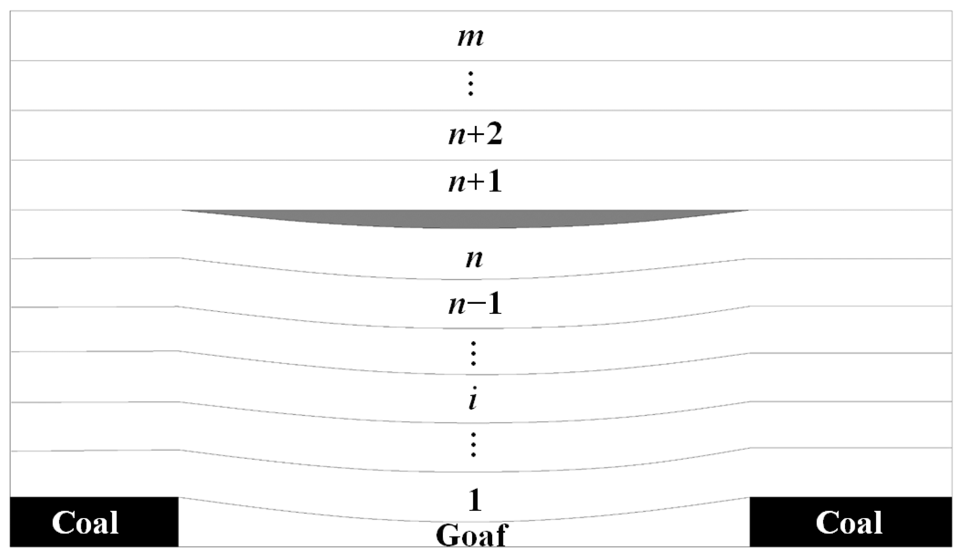
In the process of separation and fracturing development of coal seam roof strata, overburden with alternating soft and hard layers can be analyzed as a composite rock beam composed of several superimposed strata, assuming that the load on each stratum is uniformly distributed, as shown in Figure 8.
Figure 8.
Composite rock beam structure.
According to the composite beam theory, in overburden containing m layers of rocks, when adjacent layers between the 1st and nth layers can be in close contact and achieve synchronous deformation, considering the n-layer composite beam, the load on the i-th layer (i ≤ n) can be expressed as
where Ei, hi, and γi (i = 1, 2, …, n, m) are the elastic modulus (N/m2), thickness (m), and volume weight of the i-th layer (kg/m3), respectively.
According to the mine strata control theory, when the calculated (qn+1)i is less than (qn)i, it is considered that interlayer separation will occur between the (n + 1)-th layer and the n-th layer, i.e., separation is generated:
Combining Equations (1) and (2), a commonly used simplified formula can be obtained:
Since Equations (2) and (3) only compare the mechanical property differences between adjacent strata, they ignore the possible mechanical effects of strata above the (n + 1)-th layer on the (n + 1)-th layer. For example, assuming the flexural stiffness of the (n + 2)-th layer is less than that of the (n + 1)-th layer, in this case, the (n + 2)-th layer may contact the (n + 1)-th layer during subsidence, causing the (n + 1)-th layer to be squeezed by the (n + 2)-th layer and generate additional force. To address this deficiency, a correction is made: if (qm)1 = max((q1)1, (q2)1, …, (qn)1) and 1 ≤ m < n, separation will occur between the (m + 1)-th layer and the m-th layer; if (qn)1 = max((q1)1, (q2)1, …, (qn)1), no separation will occur between the 1st layer and the n-th layer.
The mechanical principle of separation space generation after correction can be explained as follows: if (qm)1 = max((q1)1, (q2)1, …, (qn)1) and 1 ≤ m < n, the 1st to m-th strata can bend synchronously in the form of a composite beam. In addition, if (qm)1 > max((qm+1)1, (qm+2)1, …, (qn)1), the deformation of each layer between the (m + 1)-th layer and the n-th layer is smaller than that of the m-th layer. Therefore, the interface between the m-th layer and the (m + 1)-th layer can be pulled apart by the m-th layer. Based on the calculation results, the closed separation spaces that cannot be formed in the mining-induced overburden fracture zone are excluded, thereby determining the development positions of separation spaces in the bending subsidence zone.
- (3)
- Equivalent model of the PG-MBSO
In view of the high alternating ratio of soft and hard rocks in overburden and small thickness of single-layer strata, the overall coordinated deformation of overburden after coal seam mining is large, and the development–closure transfer of separations is fast, making it difficult to grasp the grouting timing for single-layer separation grouting. Therefore, PG-MBSO technology is proposed, i.e., determining multi-bed grouting positions through the identification of overburden separation positions combined with overburden separation grouting conditions to realize the PG-MBSO, as shown in Figure 9.
Figure 9.
Schematic diagram of the PG-MBSO.
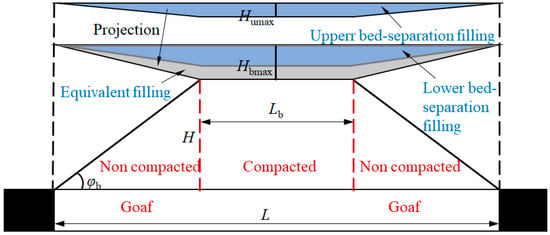
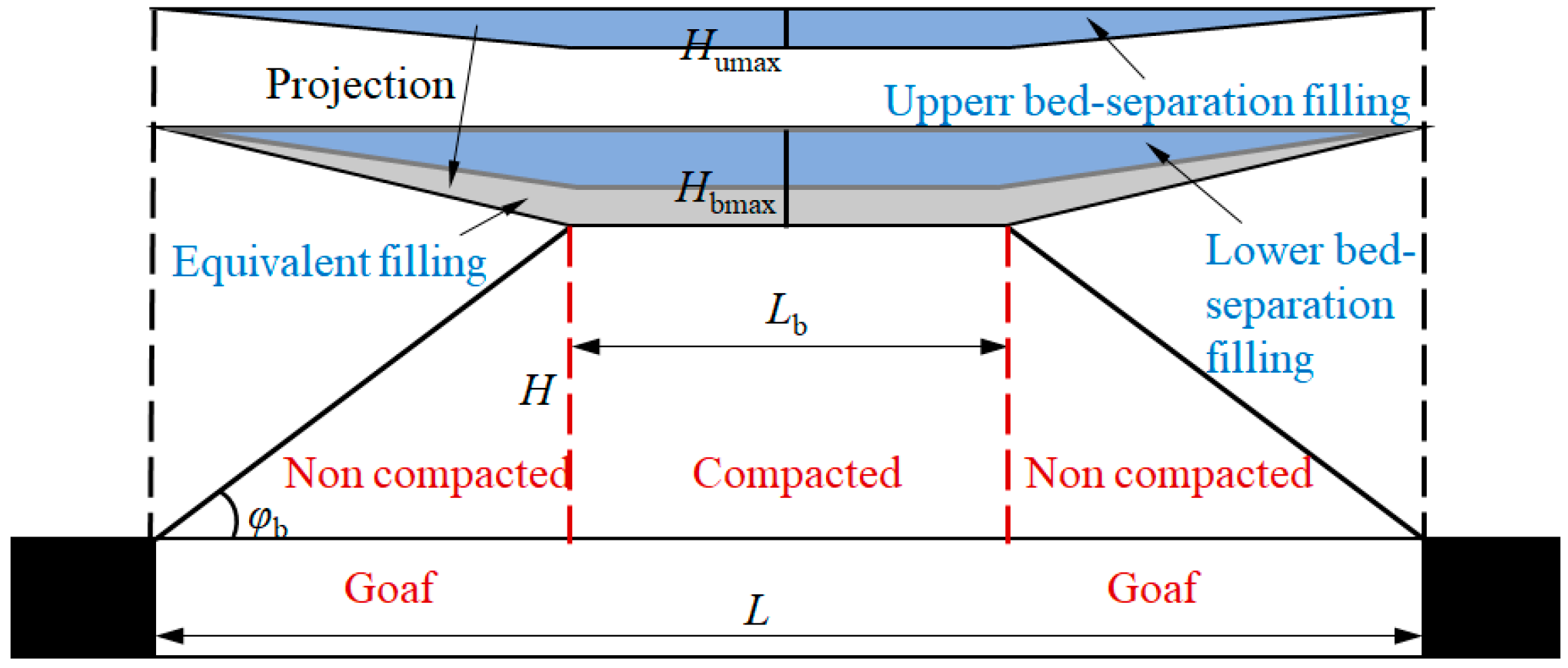
An equivalent model for the PG-MBSO is established: when the thickness of high-position grouting fillings (Humax) is 0, it is equivalent to single-layer overburden separation grouting; when Humax > 0, the high-position grouting separation fillings can be projected to the low-position grouting separation zone, making the separation zone space equivalent to an inverted trapezoid, and the filling boundaries are all located directly above the strike edge of the panel, as shown in Figure 10.
Figure 10.
Equivalent model of the PG-MBSO.
It satisfies the following geometric relationship with mining process parameters in engineering:
where Lb is the length of the flat-bottom collapse zone in the bed-separation zone, m; W is the panel width, m; Hbmax is the thickness of grouting slurry, m; L is the panel strike length, m; α is the grouting–extraction ratio (a volume ratio), generally 0.35–0.45.
Then, the thickness of grouting slurry is
where φb is the full mining angle, defined as the angle between the edge of the lowest flat part of the filling and the line connecting the upper edge of the coal seam in the strike direction of the panel, generally 50–60°.
During grouting, as the grouting pressure increases, the horizontal and vertical separation ranges of the grouting layer will further expand, and the grouting volume will increase accordingly. At the same time, the grouting pressure increases with the increase in grouting volume, causing the goaf below the grouting separation zone to be gradually compacted, closing part of the pre-developed separations below the grouting separation zone. Similarly, grouting will also generate uplift force on its overburden, and it can be considered that the subsidence of overburden above the high-position grouting separation zone is equal to the surface subsidence. Therefore, the engineering solution for surface subsidence caused by the PG-MBSO is
where Hhmax is the subsidence of the main control stratum, m; Hcmin is the minimum residual thickness of collapsed rock mass in the goaf, m; Hk is the height of the collapse zone, m; Kp is the residual bulking coefficient of collapsed rock mass.
3.2. Key Grouting Technical Parameters
The determination of key technical parameters for overburden separation grouting plays a crucial role in the grouting subsidence reduction effect, mainly including grouting pressure, stability of grout-isolating layers, grouting space volume, and grout volume.
3.2.1. Grouting Pressure
Generally, grouting pressure refers to the orifice pressure of grouting boreholes. Since grouting slurry is a homogeneous fluid, borehole pipeline grouting satisfies the Darcy–Weisbach equation; therefore, the orifice grouting pressure can be expressed as
i.e.,
where Pk is the orifice grouting pressure, MPa; ΔPs is the gravity pressure difference between the grouting filling layer and the surface, MPa; ΔPm is the pressure drop formed by the friction between slurry and grouting pipe, MPa; ΔPf is the gravity pressure difference from the orifice to the grouting layer, MPa; ρs is the average volume weight of the stratum, kg/m3; g is the gravitational acceleration, 9.8 N/kg; H is the distance from the orifice to the grouting layer, m; f is the friction coefficient; ρf is the volume weight of slurry, kg/m3; D1 is the diameter of the grouting pipe, m; v is the flow velocity of slurry, m/s.
When the grouting station is far from the grouting borehole, to ensure that the selected grouting pump can meet the grouting pressure requirements, the slurry delivery pressure at the grouting station should increase the pipeline resistance of the slurry delivery pipeline from the grouting station to the grouting borehole, i.e., the slurry delivery pressure at the grouting station can be expressed as
i.e.,
where Pr is the slurry delivery pressure at the grouting station, MPa; L is the distance from the grouting station to the grouting borehole, m; D2 is the diameter of the slurry delivery pipe, m.
The grouting pressure for overburden separation grouting can be divided into three stages: normal grouting pressure Pg in the early stage of grouting; in the middle stage of grouting, the overburden separation develops rapidly, and the grouting pressure decreases rapidly, and it is sufficient to maintain pressure grouting, i.e., Pg > 0; in the late stage of grouting, it is 1.2–1.5 times the normal grouting pressure, i.e., (1.2–1.5)Pg, to ensure that the overburden separation space is filled densely, realizing the “upper support and lower compression” grouting filling effect and controlling the deformation and damage of surrounding rock.
3.2.2. Stability of Grout-Isolating Layer
In overburden multi-bed-separation grouting engineering, the determination of grouting layers typically follows these steps: first, determining the development height of the fractured zone in the overburden to exclude rock layers below this height; second, analyzing the positions of key strata within the bending zone to identify potential bed-separation layers in the overburden and assessing whether an impermeable layer exists above the potential bed-separation layer (to prevent groundwater inflow into the separation space); and third, sequentially evaluating from bottom to top whether the thickness of the grout-isolating layer beneath each bed-separation layer that meets the aforementioned two conditions satisfies the safety requirements for grouting, thereby selecting the lowest two to three bed-separation spaces that satisfy the thickness criteria of the grout-isolating layer as the grouting layers. Extensive research has already been conducted by scholars on the first two steps [9,12,18]. This study now focuses on analyzing the third step: determining the thickness of the grout-isolating layer.
A certain thickness of strata is usually retained between the upper part of the fracture zone and the grouting layer, which is called the grout-isolating layer. The function of the grout-isolating layer is to prevent slurry from connecting with the fracture zone under the action of grouting pressure and causing slurry to rush into the underground working face along fractures, resulting in safety production accidents. Therefore, determining the thickness of the grout-isolating layer and judging its stability are necessary conditions to ensure the safety, effectiveness, and rationality of the grouting layer. Based on the elastic thin plate theory, a method for judging the stability of the grout-isolating layer is proposed by establishing a grouting filling mechanical model.
- (1)
- Mechanical model for deflection of grout-isolating layer
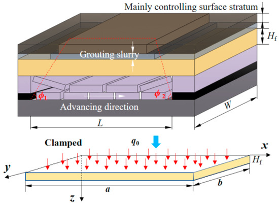
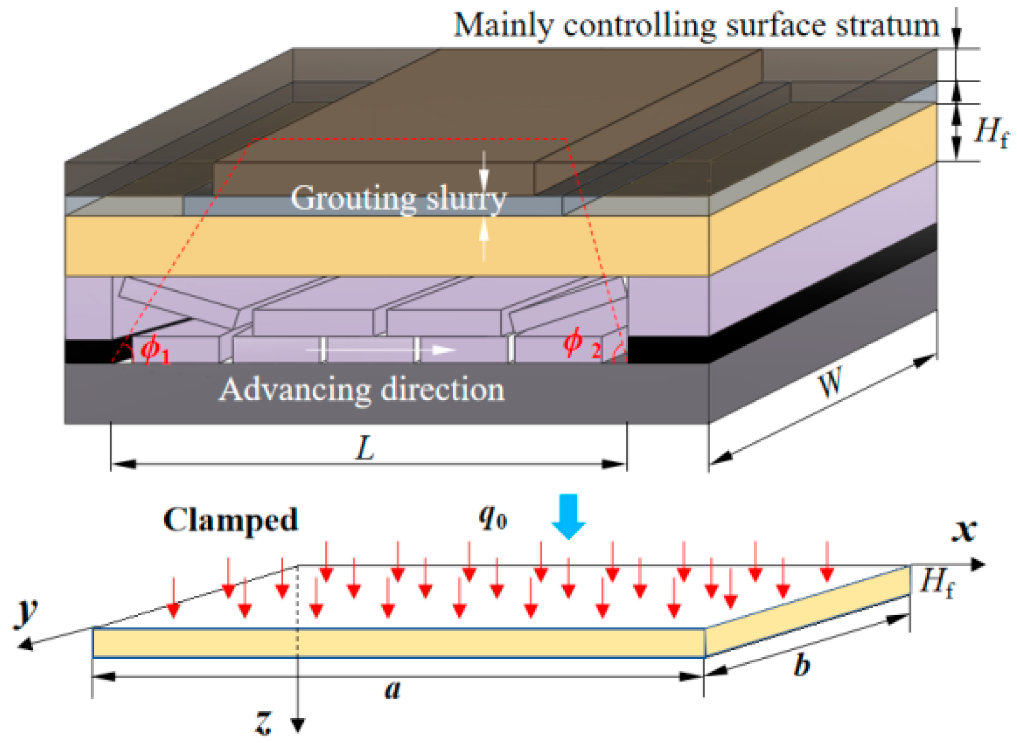
The grout-isolating layer is simplified as a single layer, and the grout-isolating layer sinks, deforms, and contacts the lower strata. Combined with the elastic thin plate theory, the deformation mechanical analysis and calculation of the grout-isolating layer are carried out, with the following assumptions first made: ➀ The grout-isolating layer is in overall contact with the lower strata, the load on the upper part of the grout-isolating layer is a uniform load, the load magnitude is the grouting layer pressure (σf), and the supporting force on the lower part of the grout-isolating layer is uniformly distributed. ➁ The strata composing the grout-isolating layer deform in an overall coordinated manner, ignoring interlayer shear action. ➂ The influence of complex geological structures such as fault weak zones on the mechanical properties of the grout-isolating layer is ignored. ➃ Both sides of the panel consist of solid coal, which provides support to the overlying strata after the panel is mined. During mining with overburden bed-separation grouting, the stress and fracture of the overlying strata above the panel are simplified as a four-edge fixed elastic composite rock plate.
A four-edge fixed elastic composite rock plate is selected as the mechanical calculation model for rock fracture of bed-separation grouting mining, as shown in Figure 11.
Figure 11.
Mechanical calculation model of grout-isolating layer.
When the separation initially develops, the upper and lower strata are fixed by surrounding strata, and each side is rigidly fixed. The boundary conditions can be expressed as
The plane thin plate bending differential equation for the grout-isolating layer strata is
where G = Eh3/12(1 − μ2) is the flexural stiffness of a single thin plate, where E, μ, and h are the elastic modulus (N/m2), Poisson’s ratio, and thickness (m) of the grout-isolating layer strata, respectively; q0 is the transverse uniform load on the grout-isolating layer strata, N/m2, which can be expressed as
where λ is the supporting coefficient of the underlying strata of the grout-isolating layer; 0 ≤ λ < 1, λ = 0 indicates that the grout-isolating layer strata are not in contact with the underlying strata; σf is the pressure of the grouting layer, MPa; Pk is the orifice pressure of the grouting borehole (MPa), and the orifice pressure gradually increases with the extension of grouting time, which can be expressed as a function of time, i.e., Pk(Δt); γf and hf are the volume weight (kg/m3) and depth (m) of the fly ash slurry, respectively; γb is the volume weight of the grout-isolating layer, kg/m3.
Let the deflection function be
It is known that the deflection function w satisfies the fixed plate boundary conditions, and taking the first term can meet the actual engineering needs. Then, for a single thin plate under the action of grouting pressure and self-weight, the deflection expression of the grout-isolating layer strata is
where a and b are the strike length and inclined width of the grout-isolating layer strata, m, which can be expressed as
where hi is the thickness of the i-th layer (m), and the n-th layer is the grout-isolating layer strata; φ1 and φ2 are the fracture angles of the strata along the advance direction of the panel, and φ3 and φ4 are the fracture angles of the strata along the width direction of the panel, generally 70–85°.
- (2)
- Instability criterion for the grout-isolating layer
The main stress distribution of the grout-isolating layer rock plate under uniform load is
According to the relationship between the main stress and stress components, the expressions of the maximum and minimum main stresses on the neutral plane (z = h/2) of the grout-isolating layer strata are
Assuming that the strata undergo shear failure, based on the Mohr-Coulomb criterion, the failure criterion of the strata is
where C and φ are the cohesion (N/m2) and internal friction angle (°) of the grout-isolating layer strata, respectively.
Substituting Equation (20) into the Mohr–Coulomb criterion, the criterion equation for damage and failure of the grout-isolating layer is obtained. When F = 1, the grout-isolating layer fractures are
To judge whether the thickness of the grout-isolating layer in overburden separation grouting is safe and reasonable during mining, it is necessary to determine the allowable thickness range of the grout-isolating layer strata, i.e.,
Therefore, in overburden separation grouting, the stability of the grout-isolating layer should be judged according to the following equation to determine whether the selection of the grouting layer is safe and feasible:
3.2.3. The Volume and Amount of Grouting
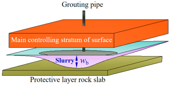
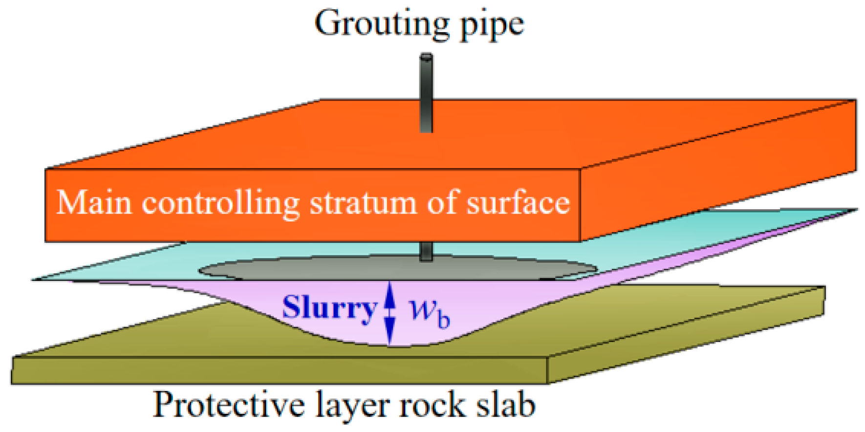
Separation spaces generally exist at the interface of soft and hard strata. As the advance distance of the coal seam increases, the deflection of soft and hard rocks in the vertical direction is inconsistent, thereby forming interlayer separations, and it can be considered that the four sides of the separation are closed areas, as shown in Figure 12.
Figure 12.
Upper and lower rock plates of bed-separation grouting.
According to Equation (15), the height of the space wb between the two plates is
where qs and qx are the transverse uniform loads on the upper and lower strata of the filling space, N/m2; Gs and Gx are the flexural stiffness of the upper and lower strata of the filling space, N/m2.
According to the research consensus in thin plate theory that the deflection at the center (a/2, b/2) of the strata is the largest, the maximum height of the grouting space is
Then, the volume of a certain separation grouting layer can be expressed as
where ws and wx are the deflections of the upper and lower rock plates at each point, m.
When adopting the PG-MBSO, the total volume of the grouting space is the sum of the volumes of each grouting space, i.e.,
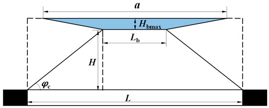
In engineering solutions, according to the actual situation of grouting engineering, grouting pressure will generate an uplift force on its overburden. For the convenience of calculation, it is assumed that the subsidence of the surface main control strata is close to zero during filling. Combined with Figure 9, an equivalent model of the grouting space for overburden separation grouting filling mining is established, as shown in Figure 13. Similarly, since the deflection at the center (a/2, b/2) of the strata is the largest, Hbmax = wbmax, which is substituted into Equation (15) and can be expressed as
Figure 13.
Equivalent model of bed-separation grouting space.
The engineering solution for the volume V of the filling separation space can be calculated as
Furthermore, the engineering solution for the grouting amount m in the overburden separation space can be expressed as
3.3. “Three-Step” Grouting Process
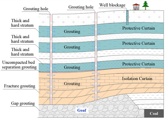
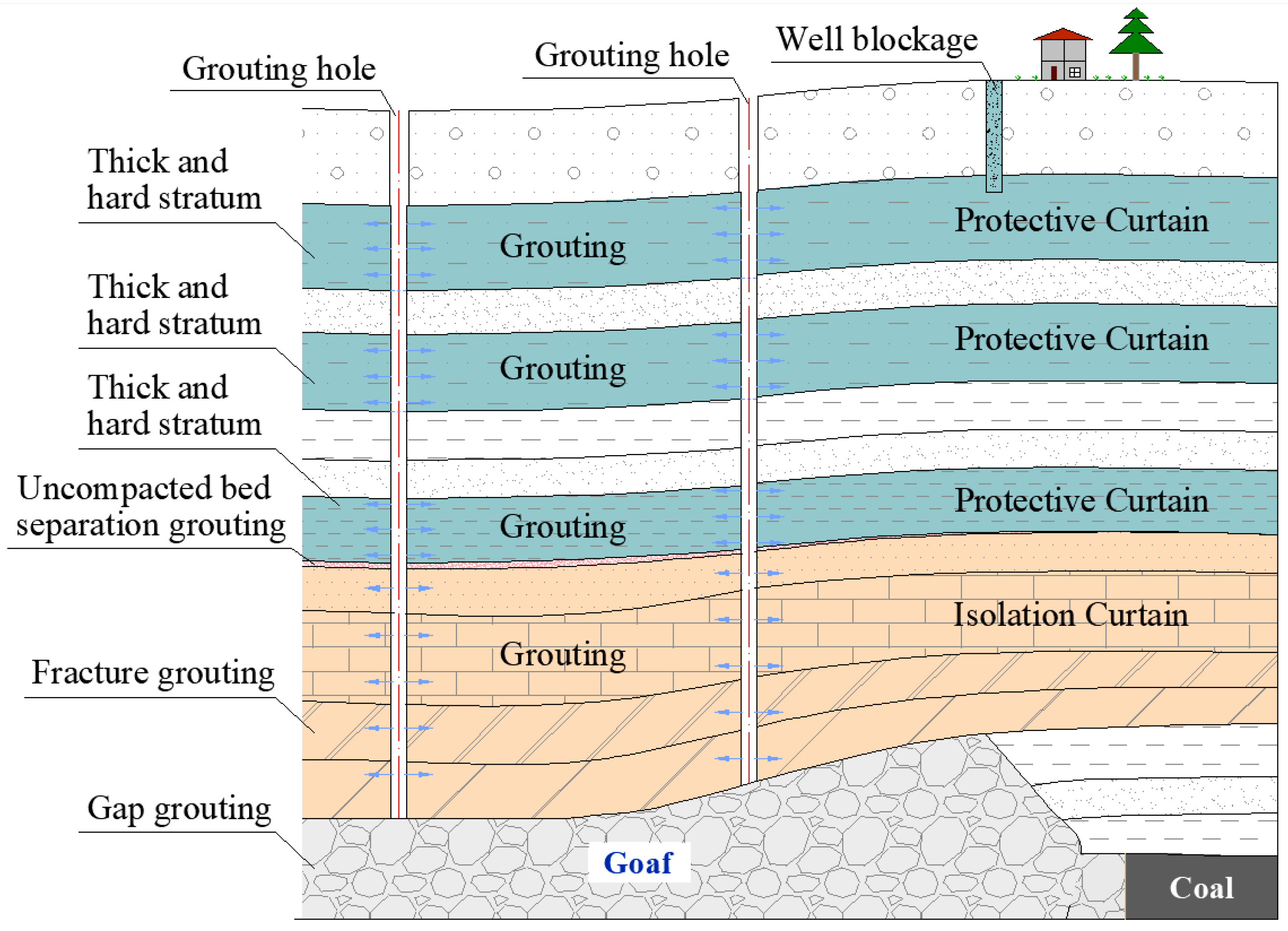
For the mining of the isolated coal pillar panel, a “three-step” precise grouting process is proposed, which comprises “separation detection and verification, fracture curtain sealing, and precise grouting for subsidence reduction,” as shown in Figure 14. The advantages of this process include accurately determining the development positions of overburden bed separations; establishing isolation and protective curtains around the bed-separation grouting layers to prevent grout loss and ensure safe panel mining; and enabling precise grouting into the bed separations generated by the panel mining, and under the auxiliary support of the curtain structure, surface subsidence is significantly controlled.
Figure 14.
“Three-step” precise grouting process for the MBSO.
- (1)
- Separation detection and verification
According to the mining of adjacent panels and the scope of goafs, boreholes are drilled at appropriate positions in adjacent goafs to master the overburden structure, detect and verify the development positions and sizes of overburden separations in goafs, and analyze the groutability of overburden separations and goafs.
- (2)
- Fracture curtain sealing
Prior to panel extraction, borehole groups are drilled in the goafs on both sides of the panel to perform grouting reinforcement on the fractured overburden of the goafs, filling the remaining separation spaces and sealing rock fractures. This process forms a protective curtain above the bed-separation grouting layer (in the vertical direction) to prevent grout leakage along vertical weak planes and fractures to the surface during bed-separation grouting in the panel, and an isolation curtain between the panel’s bed-separation grouting layer and adjacent goafs (in the horizontal direction) to prevent grout leakage along horizontal fractures into neighboring goafs. Under the protection and isolation provided by this curtain system, precise grouting into the panel’s bed-separation spaces can be achieved. Simultaneously, the curtain structures act as support strips, working in synergy with the bed-separation grout fill to effectively control surface subsidence. Additionally, since the purpose of this curtain grouting is to reinforce weak interfaces and seal fracture spaces within the strata, the grout slurry is composed of cement, fly ash, and coal gangue. Initially, the cement proportion is controlled between 15% and 30%, after which it is increased to approximately 50% until the designed grouting reinforcement pressure value is reached.
- (3)
- Precise grouting for subsidence reduction
On the basis of the above two steps, the design of overburden separation grouting for the isolated coal pillar panel is carried out, including key technical parameters such as grouting layers, borehole structure, borehole layout spacing and mode, grouting material ratio, grouting pressure, concentration, and timing. Under the protection and isolation of the constructed curtain, the PG-MBSO of the panel is realized to improve the grouting effect, and restrict the propagation and development of separations to the surface, thereby controlling surface deformation and subsidence caused by mining and achieving the purpose of safe recovery of coal resources.
4. Engineering Application
Both sides of the 12030 panel in Xinyi Mine are goafs, with severely damaged overburden and significantly developed fractures. To ensure the stability of roadways and surrounding rock, and to create favorable conditions for panel extraction, protective coal pillars with a width of 10–15 m were left unmined on both sides of the panel.
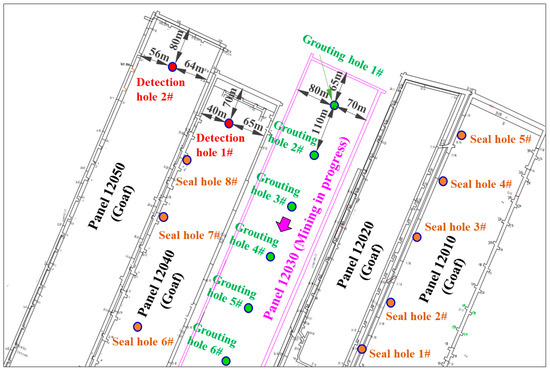
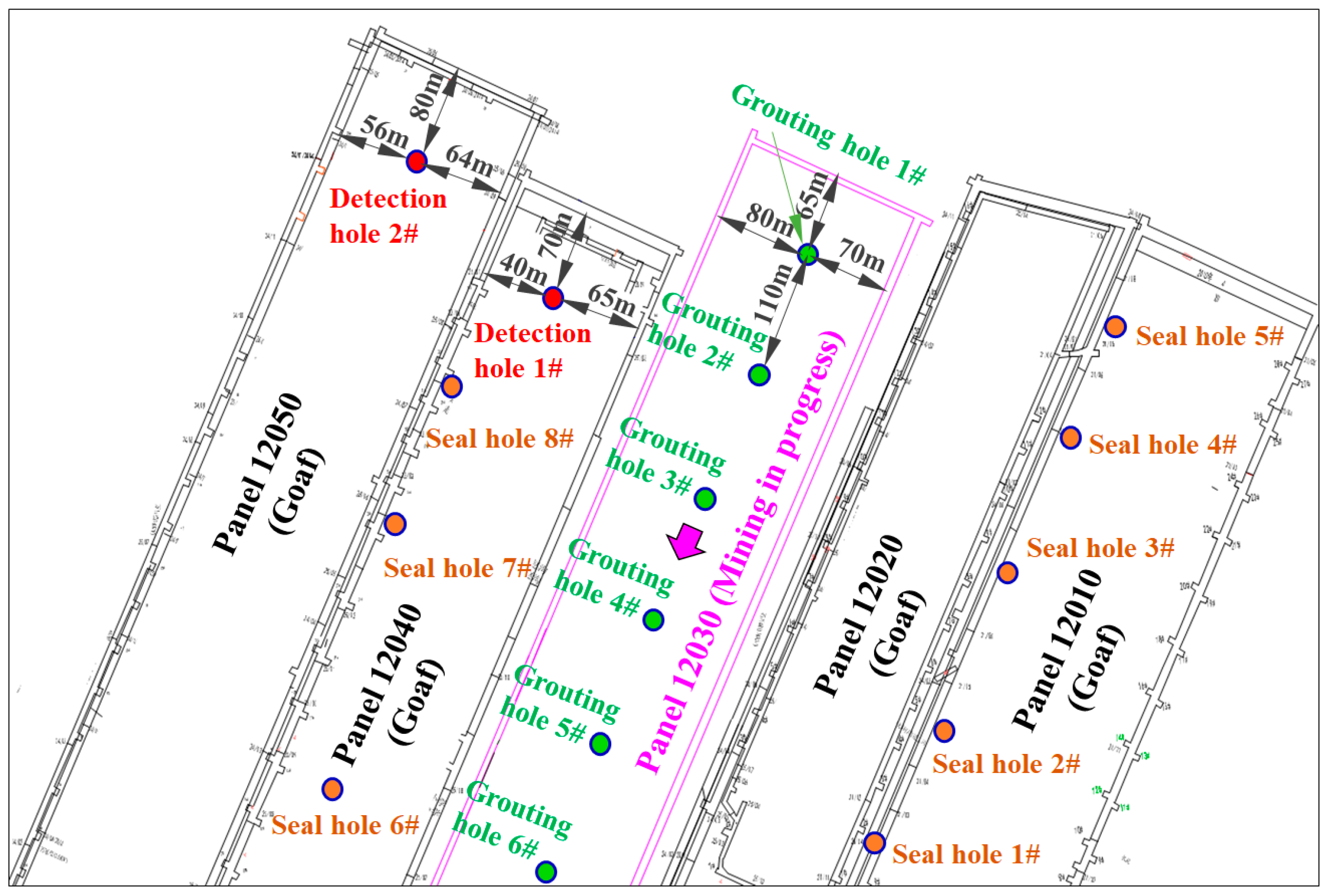
To find the development positions and residual spaces of overburden damage and the MBSO and ensure the separation grouting effect of this panel, the “three-step” precise grouting process for the MBSO, i.e., “separation detection and verification–fracture curtain sealing–precise grouting for subsidence reduction”, is applied. The borehole layout is shown in Figure 15.
Figure 15.
Borehole arrangement of “three-step” precise grouting.
4.1. Separation Detection and Verification
- (1)
- Layout of detection boreholes
The 12040 and 12050 panels are both located to the west of the 12030 panel, and both are goafs. To find out the separation positions, development conditions, and goaf groutability in goafs, two boreholes, detection holes 1# and 2#, are arranged in the goafs of the two panels. During drilling, logging and borehole coring are used to master the structural characteristics of overburden and find out the positions and development conditions of overburden separations. In addition, to analyze the goaf groutability and achieve the effective grouting filling bearing pier effect, the final hole positions of detection holes 1# and 2# need to be within the fracture zone of the No. 2-1 coal seam roof, with designed depths of 740 m and 735 m, respectively, as shown in Figure 15.
- (2)
- Grouting in detection boreholes
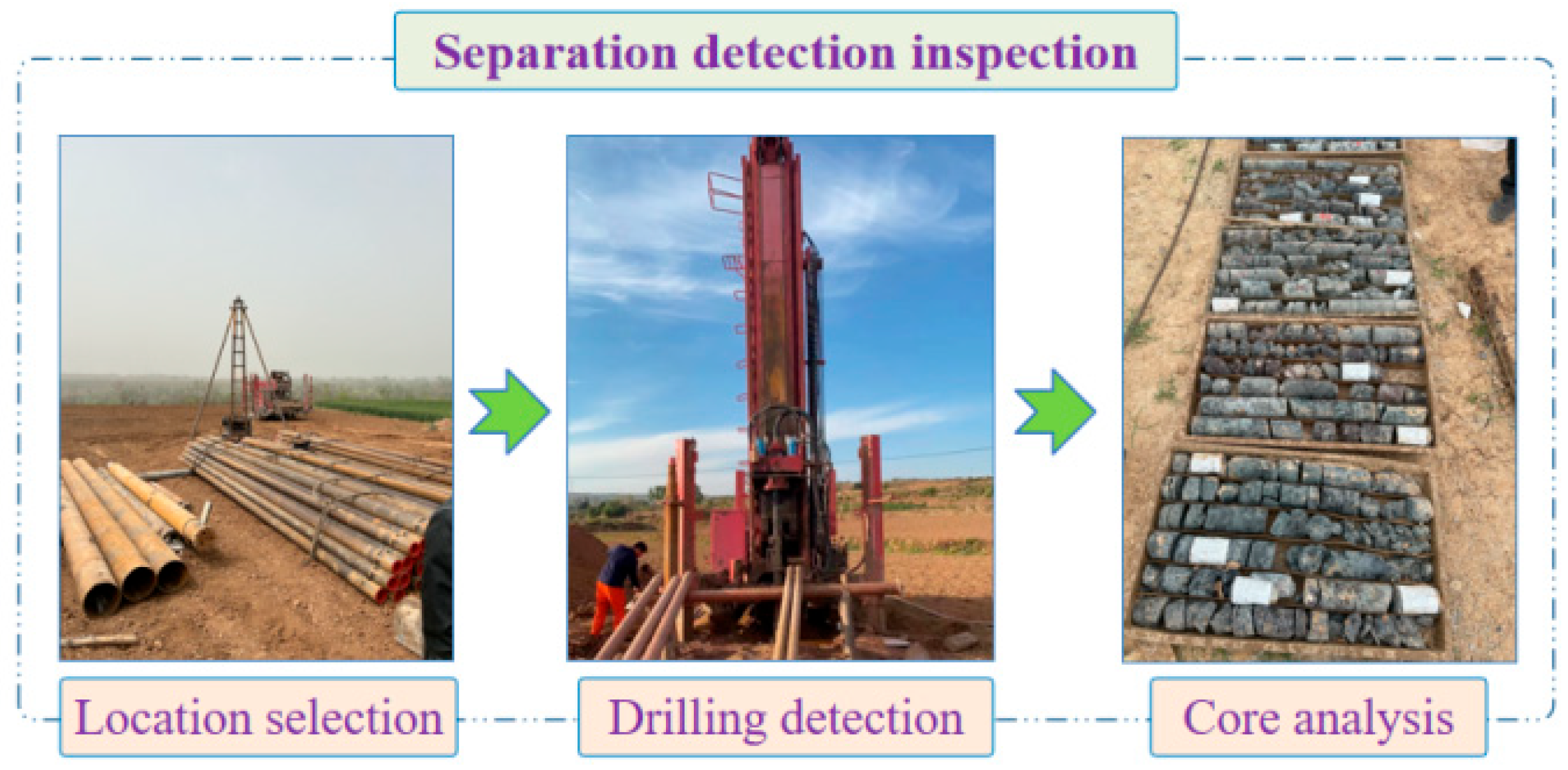
The grouting layers of detection boreholes include the goaf collapse zone, fracture zone, and separation space below the key stratum. The grouting scheme adopts the “downward grouting” method, i.e., during drilling, the leakage of flushing fluid is observed. If the flushing fluid is completely lost, drilling is stopped for grouting, and the orifice pressure for terminating grouting is 5.0–5.5 MPa. Then, drilling continues to extend downward, and grouting is performed at the next full loss position, and the cycle is repeated until extending to above the goaf collapse zone. The on-site borehole detection construction is shown in Figure 16. The grouting amounts (fly ash) of the boreholes are 6266 tons and 10,798 tons, respectively, with a total fly ash grouting amount of 17,064 tons.
Figure 16.
Separation detection and verification of overburden.
4.2. Fracture Curtain Sealing
- (1)
- Design of sealing boreholes
The 12020 and 12040 panels are located on both sides of the 12030 panel, with a mining thickness of approximately 5.0 m, and both are goafs. According to the borehole column (as shown in Figure 5), there are multiple layers of thick and hard strata in the overburden. After mining of these two panels, there is no large-area surface subsidence, with local subsidence of approximately 300 mm, from which it is inferred that both panels are in a non-full mining state, and multiple layers of thick and hard strata above the overburden fracture zone have not fractured, with a large number of separation spaces. With the mining of the 12030 panel, the goaf area increases and the full mining degree increases, which will inevitably lead to the fracture of thick and hard strata and large-area surface subsidence. In addition, the fractured strata in the overburden fracture zone and the separation spaces in the bending subsidence zone will inevitably cause a large amount of grout loss in the 12030 panel, and even accidents of slurry rushing into the underground. Therefore, sealing boreholes are constructed in the 12020 and 12040 panel goafs to, on the one hand, seal overburden fractures and fill separation spaces, form protective and isolation curtain structures, and ensure precise and efficient grouting of the 12030 panel separation space; on the other hand, the grouting-filled structures form supporting strips on both sides of the 12030 panel, cooperating with 12030 panel grouting to control surface subsidence, as shown in Figure 17.
Figure 17.
Fracture curtain sealing of overburden.
- (2)
- Grouting in sealing boreholes
The fracture curtain sealing scheme is as follows: since slurry is more likely to diffuse in the downhill direction, 5 sealing boreholes (seal holes 1–5#) are arranged in the 12020 panel (located in the downhill direction of the 12030 panel) for sealing, and 3 sealing boreholes (seal holes 6–8#) are arranged in the 12040 panel (located in the uphill direction of the 12030 panel) for sealing, as shown in Figure 15. The grouting layers include the goaf collapse zone, fracture zone, and separation spaces in the bending subsidence zone. The fracture curtain sealing still adopts the “downward grouting” method, which is different from the aforementioned separation detection borehole grouting: first, the orifice pressure for terminating grouting is 3.5–4.0 MPa; second, a certain proportion of cement is added to the grouting material to control the grouting diffusion area and form supporting strips with sufficient strength. The grouting amounts (fly ash and cement) in the 12020 and 12040 panels are 68,523 tons and 20,299 tons, respectively, with a total grouting amount of 88,822 tons.
4.3. Precise Grouting for Subsidence Reduction
After completing the fracture curtain sealing in the 12020 and 12040 panels, the mining and grouting operations of the 12030 panel are carried out, adopting the immediate grouting filling method with simultaneous mining and grouting and matching grouting with mining.
- (1)
- Borehole layout
A total of 6 grouting boreholes are arranged in the 12030 panel, numbered grouting hole 1–6#, with a borehole spacing of approximately 110 m (drawing on the practical experience from overburden bed-separation grouting operations in other panels), as shown in Figure 15. The borehole structure is as follows: a φ245 mm casing is set at the first opening depth of 65 m, a φ178 mm casing is set at the second opening depth of 360 m, and a φ139 mm screen pipe is set at the third opening depth of 500 m.
- (2)
- Grouting layer
In China, the fractured zone height has been determined based on extensive field observations and experimental studies across hundreds of mines. By considering factors such as coal seam thickness, mining method, coal seam dip angle, and the strength characteristics of the overlying strata, statistical calculation formulas have been developed to estimate the height under different overburden conditions. These predictive formulas have been incorporated into the Guidelines for Coal Pillar Design and Mining under Buildings, Water Bodies, Railways, and Major Roadways, providing guidance for practical mining operations [35]. The equation is shown in Table 1.
Table 1.
Calculation equations for the fractured zone in thick-seam top-coal caving (longwall) mining [35].
The equations in Table 1 are widely used to determine the height of the fractured zone. The mining panel has a coal seam thickness of 5.0 m, and the overburden lithology is classified as medium–hard. Based on the formula (Type 1), the calculated height of the fractured zone ranges from 58.55 to 79.39 m. Combined with on-site borehole detection results, the actual height of the fractured zone is determined to be 73.6 m. Through the aforementioned separation detection and fracture curtain sealing, combined with the borehole column (as shown in Figure 5), the overburden has alternating soft and hard strata, forming multiple layers of separation spaces. Based on comprehensive analysis, the first grouting layer was determined to be fine–medium grained sandstone (a sub-key stratum) with a burial depth of 499.85 m and a thickness of 12.36 m. Above it exists a mudstone layer with a thickness of 12.14 m that serves as an aquiclude. The grout-isolation layer thickness is 186.25 m (calculated as coal seam burial depth of 759.7 m minus fractured zone development height of 73.6 m minus grouting layer burial depth of 499.85 m), which fully meets the engineering requirements. The second grouting layer is siltstone (a sub-key stratum) with a burial depth of 449.35 m and a thickness of 4 m. Above it exists a mudstone layer with a thickness of 12.37 m that serves as an aquiclude.
- (3)
- Grouting pressure
The grouting layer is approximately 500 m from the surface, the formation volume weight is 2.5 t/m3, the grouting material volume weight is 1.5 t/m3, and the pipeline friction resistance loss is 0.3 MPa. The normal grouting pressure of the grouting borehole is 5.3 MPa. The grouting pressure in the early stage is the normal grouting pressure of 5.3 MPa, the pressure is maintained in the middle stage of grouting, and the pressure in the late stage is 6.4–8.0 MPa.
- (4)
- Grouting timing
According to the experience of bed-separation grouting, the grouting conditions are generally met when the working face mining position advances to 20 m from the bottom of the borehole. Under hard rock conditions, separation may occur after the working face passes through the borehole. Therefore, the grouting boreholes should be drilled in advance and filled with water for pressure maintenance. Once water loss and pressure drop occur, indicating that mining-induced fractures start to develop, trial grouting can be carried out. Since the 12030 panel is an isolated coal pillar with poor rock integrity, water pressure tests are conducted on the boreholes when the working face is within 50 m of the borehole bottom to ensure timely mastery of grouting timing.
- (5)
- Water–cement ratio
The slurry volume concentration is adjusted in real time according to the actual grouting situation, ranging from not less than 50% to not more than 75%.
- (6)
- Borehole grouting
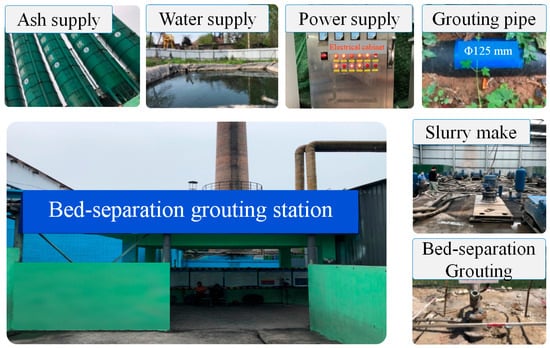
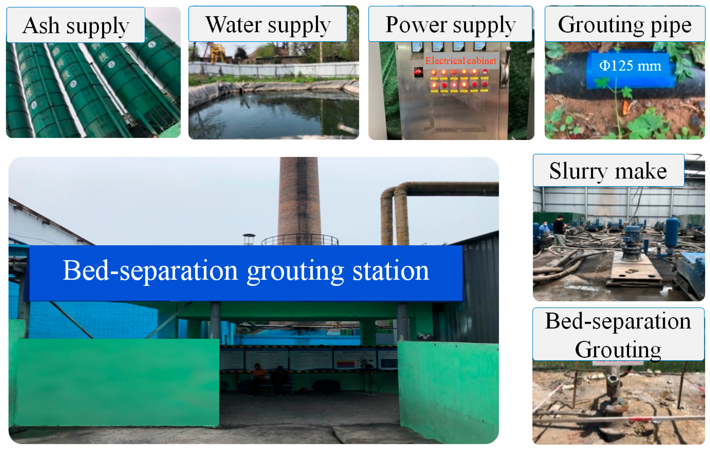
Grouting in the 12030 panel started on 1 February 2021 and ended on 23 November 2022, lasting 660 days, as shown in Figure 18. The mining height of the panel is 5.0 m, the mining volume is approximately 934,500 m3, 1,364,400 tons of coal resources under villages is mined, the actual grouting amount is 398,622 tons, the volume is 498,278 m3, and the grouting–extraction ratio reaches 0.53 (volume ratio).
Figure 18.
Bed-separation grouting system of Xinyi Coal Mine.
5. Discussion
5.1. Characteristics of the PG-MBSO
In view of the high alternating ratio of soft and hard rocks in the overburden above the mined coal seam, small thickness of single-layer strata, large overall coordinated deformation of overburden after mining, and fast development–closure transfer of separations, single-layer grouting causes difficulties in grasping the grouting timing and has a poor grouting effect. Therefore, the PG-MBSO technology is proposed (as shown in Figure 9).
In comparison to conventional single-bed-separation grouting, the PG-MBSO presents the following advantages:
- (1)
- Effectively controls surface subsidence: The PG-MBSO can more effectively utilize separation spaces, increase grouting volume, control the movement and deformation of overburden, effectively reduce the range and amplitude of surface subsidence, and improve the stability and reliability of overburden surface treatment effects.
- (2)
- Enhanced bearing capacity: Grouting in multiple bed separations can more evenly distribute the overburden load pressure and enhance the overall bearing capacity of the strata.
- (3)
- Wider adaptability: It can adapt to different overburden mining conditions and is more applicable to complex geological and stratigraphic structures, such as those encountered during the recovery of isolated coal pillars. Moreover, by targeting multiple strata for grouting as opposed to a single layer, it is easier to locate suitable injection horizons, initiate grouting in a more timely manner, and ultimately enhance the effectiveness of subsidence control. Therefore, it performs effectively in weak overburden lacking clearly identifiable key strata.
- (4)
- Long-term stability: A key consideration in multi-bed-separation grouting is the potential interaction between sequentially filled layers. The PG-MBSO approach fundamentally differs from a rigid sequential grouting operation (e.g., strictly bottom-up or top-down). Instead, it employs a dynamic, responsive strategy grounded in the observed mechanics of overburden separation development. Since the lowest bed separation develops first and achieves the largest space, it naturally receives the earliest and largest volume of grout, forming the primary load-bearing component. Concurrently, grouting of the upper bed separation is initiated not in a predetermined order, but as a compensatory measure to ensure timely filling as the separation front propagates upward. This prevents the formation of unfilled voids—a common limitation of single-layer grouting. Thus, the grout injected into multi-bed separations interacts synergistically: the lower grout body acts as the main supporting base, while the upper grout layers provide supplementary confinement. Together, they form a coherent, integrated “up-lift and down-compaction” composite structure that enhances the overall load-bearing capacity of the grout–rock system. This collaborative mechanism ensures that filling upper bed separations does not adversely alter the closure dynamics of lower bed separations but rather improves the completeness of the fill and promotes long-term stability, thereby optimizing the net subsidence control efficiency of the PG-MBSO process.
5.2. Grouting Pressure of the PG-MBSO
Grouting pressure serves as a critical regulating parameter for achieving the desired grouting outcome. When the grouting pressure is too high, once it exceeds the deflection limit of the rock plate, it will lead to rock instability, resulting in hazards such as surface grout leakage and underground slurry inrush. When the grouting pressure is low, it will lead to poor filling solidification effect of strata grouting and fail to achieve the effect of overburden grouting for upper support and lower compression. To avoid excessive supporting pressure on the overburden leading to surface uplift damage, the grouting pressure is usually moderate. However, due to the need for grouting in multiple layers, the pressure for the PG-MBSO generally needs to be higher to ensure that the slurry can fully fill the separation spaces. In addition, the grouting pressure also needs to be adjusted according to factors such as rock properties, separation development conditions, and grouting equipment capacity.
In addition, the diffusivity of slurry increases proportionally with grouting pressure, which directly affects the grouting filling effect. If the diffusivity of slurry is poor, it may lead to the inability of the slurry to fully fill the target position, thereby causing excessive surface subsidence. Due to the complexity of separation spaces and the characteristics of the MBSO, the diffusivity of slurry in the PG-MBSO may be affected to a certain extent. Compared with conventional bed-separation grouting, the PG-MBSO requires finer regulation of slurry diffusivity to achieve precise injection. To improve the diffusivity of slurry, in addition to increasing grouting pressure, some special grouting materials and grouting processes can be adopted.
5.3. Subsidence Reduction of the PG-MBSO
Observation stations are established along the strike and dip directions on the surface of the 12030 panel (as shown in Figure 4). Continuous observation is carried out during grouting mining, and the surface movement and deformation laws under normal mining and PG-MBSO mining are compared and analyzed to obtain the subsidence reduction and damage control situation of the PG-MBSO mining.
- (1)
- Surface movement and deformation
The surface movement and deformation parameters under normal mining conditions are obtained by prediction using the probability integral method, and the prediction parameters are obtained by analyzing the previously measured data of the coal mine, as shown in Table 2. The comprehensive evaluation coefficient P of the overburden in the mine is calculated to be 0.34, and the subsidence coefficient q = 0.5(0.9 + P) = 0.62.
Table 2.
Probability integral method calculation parameters.
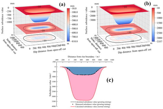
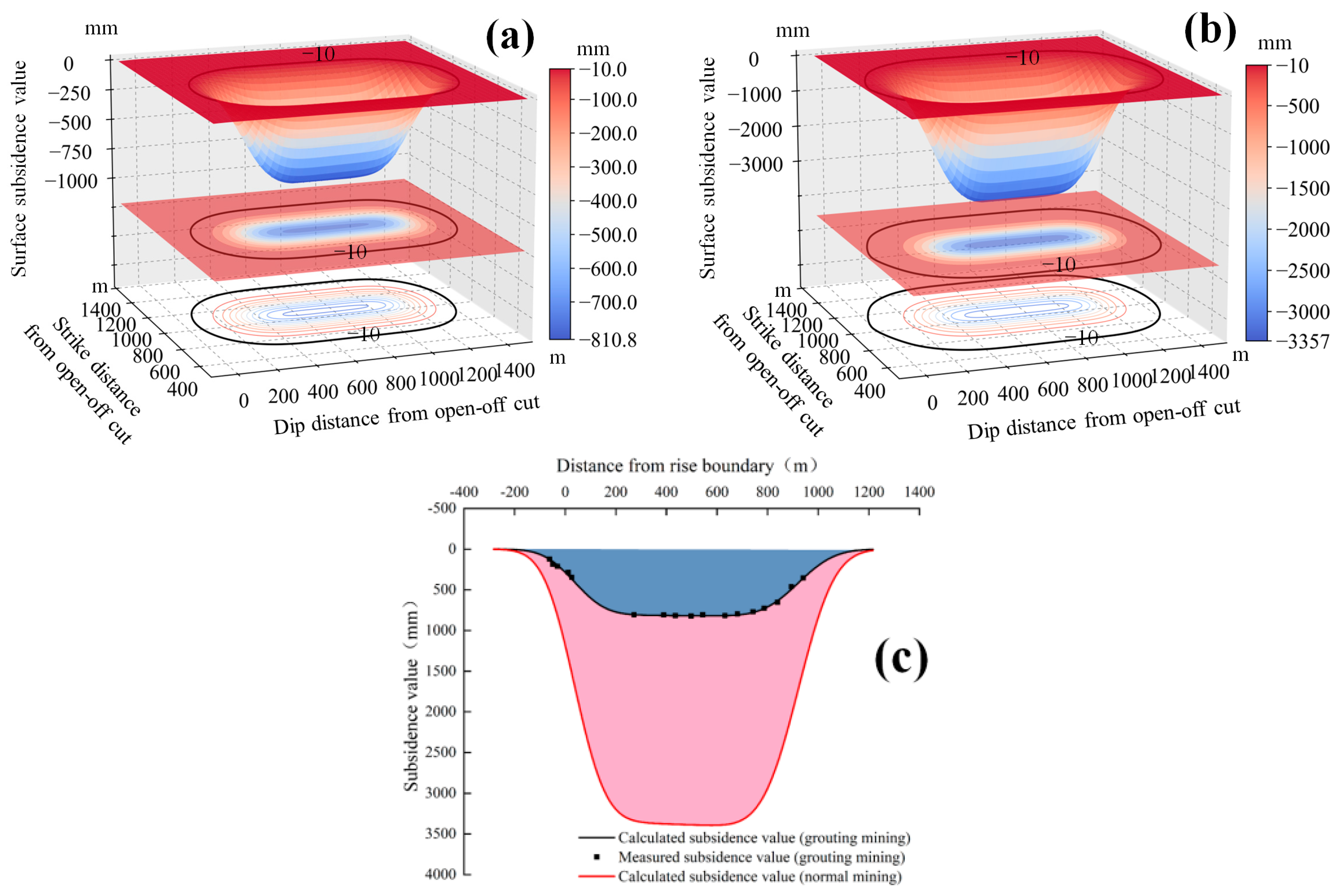
The surface movement and deformation parameters under the PG-MBSO mining conditions are calculated based on measured results. A total of five survey lines are arranged above the panel, with 19 measuring points for line A, 14 for line B, 15 for line C, 19 for line D, and 17 for line E, totaling 84 measuring points, as shown in Figure 4. The surface subsidence values under normal mining and the PG-MBSO mining conditions are shown in Figure 19.
Figure 19.
Mining-induced surface subsidence of 12030 panel: (a) PG-MBSO mining; (b) prediction of normal mining; (c) comparison of surface subsidence values for two mining schemes.
Figure 19 demonstrates the significant effectiveness of PG-MBSO in controlling surface subsidence. Without this technology, subsidence in panel 12030 would have been 3393.9 mm, whereas its application reduced the maximum value to 821 mm—a reduction rate of approximately 75.81%.
- (2)
- Building deformation and damage
The maximum values of surface movement and deformation under normal mining and the PG-MBSO mining conditions are shown in Table 3.
Table 3.
Statistics of maximum surface movement and deformation of 12030 panel.
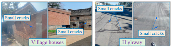
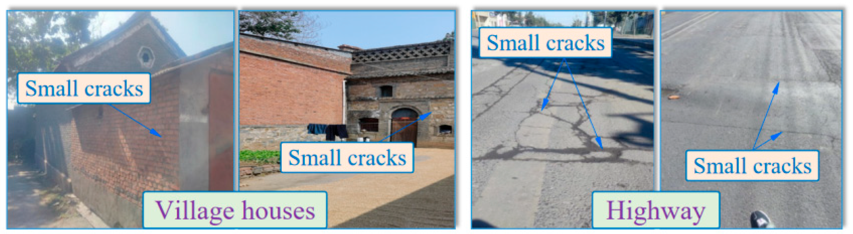
Table 3 shows that when traditional caving mining (non-grouting) is employed, the maximum surface horizontal deformation value reaches 18.6 mm/m. After adopting PG-MBSO mining, the surface inclination, curvature, and horizontal deformation values are significantly reduced. Referring to the damage grade standard for masonry structure buildings, the damage grade of surface buildings using PG-MBSO mining can be controlled within Grade I (horizontal deformation ε ≤ 2.0 mm/m, curvature K ≤ 0.2 mm/m2, inclination i ≤ 3.0 mm/m). Through on-site investigation of the surface and important structures, except for a few minor cracks in the houses and roads above the panel that need repair, no obvious damage has occurred, and the maximum deformation values of most civilian houses are within Grade I damage, indicating that surface structures are effectively protected and the subsidence reduction effect of the PG-MBSO is obvious, as shown in Figure 20.
Figure 20.
Damage to surface buildings and structures.
While this study demonstrates the effectiveness of the PG-MBSO approach in controlling surface subsidence, its implications for adjacent roadway stability, particularly under conditions of gob-side roadway retention, warrant further consideration. In the present case of isolated pillar recovery, the adjacent roadway was not intended for reuse and therefore will not be retained. However, for longwall panels where roadway retention is essential, the mechanical interactions between grouting pressure, overburden deformation, and roadway stability become critical. Future research should systematically evaluate how grouting parameters—such as timing, pressure, and slurry properties—affect stress redistribution and deformation around goaf-side roadways. Such work would extend the applicability of bed-separation grouting from subsidence mitigation to holistic ground control in complex mining layouts.
6. Conclusions
- (1)
- The formation mechanism of the MBSO is elaborated, the development positions of the MBSO are determined, an equivalent model for the PG-MBSO is established, and an engineering solution for surface subsidence caused by the PG-MBSO is given.
- (2)
- The key technical parameters of the PG-MBSO are theoretically analyzed. The calculation methods for grouting orifice pressure and grouting station slurry delivery pressure considering pipeline resistance are given. The stability criterion for the grout-isolating layer of the PG-MBSO and the calculation methods for grouting space volume and grouting amount are proposed.
- (3)
- Aiming at the situation of surrounding goafs and severe overburden damage of the isolated coal pillar panel, a “three-step” precise grouting process for the MBSO is proposed. Separation detection and verification: Determine the location and size of bed separations in goafs. Fracture curtain sealing: Establish protective and isolation curtains around the grouting layer. Precise grouting for subsidence reduction: Conduct PG-MBSO to control surface subsidence.
- (4)
- The “three-step” precise grouting technology is tested in panel 12030 of Xinyi Mine, determining borehole parameters, grouting parameters, and phased grouting plans. Two detection holes, eight seal holes, and six grouting holes are completed, with a total grouting amount of 504,500 tons (fly ash and cement), including 398,600 tons for PG-MBSO. As a result, 1,364,400 tons of coal resources beneath villages is mined at a grouting–extraction ratio of 0.53 (volume ratio).
- (5)
- The advantages and pressure control characteristics of the PG-MBSO are discussed. Compared to conventional mining, PG-MBSO reduced surface subsidence by approximately 75.81%, maintaining building damage within Grade I. This demonstrates the significant subsidence control and damage mitigation capability of PG-MBSO, enabling safe and green mining of coal resources beneath villages under complex geological conditions.
Author Contributions
Methodology, formal analysis, writing—review, H.Y.; conceptualization, writing—original draft, M.G.; methodology, formal analysis, editing, W.G.; formal analysis, investigation, writing—review, M.J.; formal analysis, writing—review, supervision, D.P.; formal analysis, writing—review, S.T.; data curation, investigation, Y.G.; formal analysis, writing—review, G.L.; formal analysis, investigation, E.B. All authors have read and agreed to the published version of the manuscript.
Funding
This work was supported by the National Natural Science Foundation of China (U21A20108), the National Natural Science Foundation of China (52322403), and the Research fund of Henan Key Laboratory for Green and Efficient Mining & Comprehensive Utilization of Mineral Resources (Henan Polytechnic University) (KCF202002).
Data Availability Statement
The original contributions presented in the study are included in the article; further inquiries can be directed to the corresponding author.
Acknowledgments
The authors appreciate the financial support of this work provided by the National Natural Science Foundation of China (U21A20108); the National Natural Science Foundation of China (52322403); Research fund of Henan Key Laboratory for Green and Efficient Mining & Comprehensive Utilization of Mineral Resources (Henan Polytechnic University) (KCF202002). The authors also thank the editor and anonymous reviewers for their efforts.
Conflicts of Interest
Authors Heng Yang, Mingkui Jia and Yu Guo were employed by the company Henan Energy Group Co., Ltd. Authors Dafeng Pi, Shijie Tang, Guodong Li and Mingjie Guo were employed by the company Jiaozuo Coal Industry (Group) Co., Ltd., Henan Energy Group Co., Ltd. The remaining authors declare that the research was conducted in the absence of any commercial or financial relationships that could be construed as a potential conflict of interest.
References
- Wang, Q.; Ren, Z.P.; Bai, Q.S.; Li, Q.S. Characterizing the effect of longwall retreating speeds on overburden and surface synergistic subsidence behaviors with a thick coal seam: Intensive field measurements. J. Geophys. Eng. 2024, 21, 169–183. [Google Scholar] [CrossRef] [Scilit]
- Liu, G.; Zhang, W.; Zou, Y.; Chai, H.; Xue, Y. Numerical study on characteristics of bedrock and surface failure in mining of shallow-buried MCS. Energies 2022, 15, 3446. [Google Scholar] [CrossRef] [Scilit]
- Wu, Z.Y.; Niu, Q.H.; Li, W.P.; Lin, N.H.; Liu, S.L. Ground stability evaluation of a coal-mining area: A case study of Yingshouyingzi mining area, China. J. Geophys. Eng. 2018, 15, 2252–2265. [Google Scholar] [CrossRef] [Scilit]
- Srivastava, V.; Jha, P.K. Environmental impacts of coal mining and mitigation measures: A review. Environ. Monit. Assess. 2025, 197, 545. [Google Scholar] [CrossRef] [Scilit]
- Li, L.; Huang, Q.; Zuo, X.; Wu, J.; Wei, B.; He, Y.; Zhang, W.; Zhang, J. Study on the slurry diffusion law of fluidized filling gangue in the caving goaf of thick coal seam fully mechanized caving mining. Energies 2022, 15, 8164. [Google Scholar] [CrossRef] [Scilit]
- Xie, H.P.; Wang, G.F.; Ren, H.W.; Liu, Q.M.; Ren, S.H. Green and sustainable mining: Underground coal mining model with backfilling and its key technologies. J. China Coal Soc. 2019, 44, 64–75. (In Chinese) [Google Scholar] [CrossRef]
- Huang, P.; Spearing, A.J.S.; Feng, J.; Jessu, K.V.; Guo, S.A. Effects of solid backfilling on overburden strata movement in shallow depth longwall coal mines in West China. J. Geophys. Eng. 2018, 15, 2194–2208. [Google Scholar] [CrossRef] [Scilit]
- Yang, M.M.; Wang, M.; Wang, Y.W.; Zhang, J.G.; Zhang, L.; Wang, Z.P. Coal pore structure changes in upper protective seam after mining: Pingdingshan Shenma Group, Henan Province, China. J. Pet. Sci. Eng. 2022, 218, 111045. [Google Scholar] [CrossRef] [Scilit]
- Guo, W.B.; Guo, M.J.; Tan, Y.; Bai, E.H.; Zhao, G.B. Sustainable development of resources and the environment: Mining-induced eco-geological environmental damage and mitigation measures—A case study in the Henan coal mining area, China. Sustainability 2019, 11, 4366. [Google Scholar] [CrossRef] [Scilit]
- Wang, B.; Zhu, S.; Jiang, F.; Liu, J.; Shang, X.; Zhang, X. Investigating the width of isolated coal pillars in deep hard-strata mines for prevention of mine seismicity and rockburst. Energies 2020, 13, 4293. [Google Scholar] [CrossRef] [Scilit]
- Zhu, W.; Yu, S.; Xu, J. Influence of the elastic dilatation of mining-induced unloading rock mass on the development of bed separation. Energies 2018, 11, 785. [Google Scholar] [CrossRef] [Scilit]
- Bai, E.H.; Wang, R.L.; Guo, W.B.; Tan, Y.; Lei, W.F.; Li, H.; Wei, Z.Y. Green coal mining technology of overburden grout injection with directional drilling under buildings. Bull. Eng. Geol. Environ. 2025, 84, 391. [Google Scholar] [CrossRef] [Scilit]
- Jiang, Z.H.; Jiang, B.; Zhang, C.; Ma, Y.K.; Wang, Y.T.; Li, D.H.; Wang, S. Research on cooperative control method of comprehensive pressure relief and anchor grouting reinforcement in deep mining roadways. Geomech. Geophys. Geo Energy Geo Resour. 2024, 10, 79. [Google Scholar] [CrossRef] [Scilit]
- Cao, Z.Z.; Xiong, Y.; Xue, Y.; Du, F.; Li, Z.H.; Huang, C.H.; Wang, S.R.; Yu, Y.Q.; Wang, W.Q.; Zhai, M.L.; et al. Diffusion evolution rules of grouting slurry in mining-induced cracks in overlying strata. Rock Mech. Rock Eng. 2025, 58, 6493–6512. [Google Scholar] [CrossRef] [Scilit]
- Zhao, T.; Liu, C.Y. Roof instability characteristics and pre-grouting of the roof caving zone in residual coal mining. J. Geophys. Eng. 2017, 14, 1463–1474. [Google Scholar] [CrossRef] [Scilit]
- Wang, R.; Bai, J.B.; Yan, S.; Chang, Z.G.; Wang, X.Y. An innovative approach to theoretical analysis of partitioned width & stability of strip pillar in strip mining. Int. J. Rock Mech. Min. 2020, 129, 104301. [Google Scholar] [CrossRef] [Scilit]
- Guo, M.J.; Guo, W.B.; Tan, Y.; Zhang, H.B.; Zheng, Q.L.; Zhao, G.B.; Bai, E.H. Ground control by L-shaped cemented paste backfilling technology in underground coal seam mining: A case study. Geomech. Geophys. Geo Energy Geo Resour. 2024, 10, 31. [Google Scholar] [CrossRef] [Scilit]
- Xuan, D.Y.; Xu, J.L.; Wang, B.L.; Teng, H. Borehole investigation of the effectiveness of grout injection technology on coal mine subsidence control. Rock Mech. Rock Eng. 2015, 48, 2435–2445. [Google Scholar] [CrossRef] [Scilit]
- Guo, W.B.; Li, L.X.; Yang, W.Q.; Bai, E.H.; Wu, D.T. Determination of grouting layer and stability analysis of slurry-resisting overburden in separation grouting. J. China Coal Soc. 2025, 50, 264–280. (In Chinese) [Google Scholar] [CrossRef]
- Guo, P.; Zhao, W.; Ma, Y.; Gen, H. Discrete element analysis of grouting reinforcement and slurry diffusion in overburden strata. Appl. Sci. 2025, 15, 8464. [Google Scholar] [CrossRef] [Scilit]
- Sakhno, I.; Zuievska, N.; Xiao, L.; Zuievskyi, Y.; Sakhno, S.; Semchuk, R. Prediction of Water Inrush Hazard in Fully Mechanized Coal Seams’ Mining Under Aquifers by Numerical Simulation in ANSYS Software. Appl. Sci. 2025, 15, 4302. [Google Scholar] [CrossRef] [Scilit]
- Ji, J.S.; Li, Z.H.; Yang, K.; Zhou, G.H.; Ma, G.J.; Liu, C.; Zhou, P. Research on formation mechanism and evolution pattern of bed separation zone during repeated mining in multiple coal seams. Geofluids 2022, 2022, 4290063. [Google Scholar] [CrossRef] [Scilit]
- Wang, J.; Ma, J.; Yang, K.M.; Yao, S.Y.; Shi, X.Y. Effects and laws analysis for the mining technique of grouting into the overburden bedding separation. J. Clean. Prod. 2021, 288, 125121. [Google Scholar] [CrossRef] [Scilit]
- Li, J.; Xuan, D.Y.; Xu, J.L.; Dong, Z.B.; Wang, C.C. Compaction response of mining-induced rock masses to longwall overburden isolated grouting. Minerals 2023, 13, 633. [Google Scholar] [CrossRef] [Scilit]
- Li, Y.X.; Ma, J.; Yang, K.M.; Jiang, K.G.; Gu, X.R.; Peng, L.S.; Chen, X.Y. Isolated overburden grout injection technology mining and grouting parameters discussion and optimization. Environ. Earth Sci. 2024, 83, 264. [Google Scholar] [CrossRef] [Scilit]
- Zheng, J.; Zhou, G.Q.; Zhou, Y.L.; Yuan, D.F.; Zhao, T.L. Bed separation characteristics of an LTCC panel and subsidence controlling grouting: Case study of Longquan Coal Mine, China. Shock Vib. 2022, 2022, 3837625. [Google Scholar] [CrossRef] [Scilit]
- Wang, X.Y.; Wu, W.D.; Wu, B.W. Grouting of bed separation spaces to control sliding of the high-located main key stratum during longwall mining. Q. J. Eng. Geol. Hydrogeol. 2020, 53, 569–578. [Google Scholar] [CrossRef] [Scilit]
- Xuan, D.Y.; Xu, J.L. Grout injection into bed separation to control surface subsidence during longwall mining under villages: Case study of Liudian coal mine, China. Nat. Hazards 2014, 73, 883–906. [Google Scholar] [CrossRef] [Scilit]
- Xu, Y.P.; Lin, B.Q.; Liu, T.; Cao, J.W.; Liu, T. Influence law and control mechanism of overburden isolated grout injection on methane emission in the working face. J. Clean. Prod. 2023, 430, 139612. [Google Scholar] [CrossRef] [Scilit]
- Ma, H.W.; Sui, W.H.; Ni, J.M. Environmentally sustainable mining: A case study on surface subsidence control of grouting into overburden. Environ. Earth Sci. 2019, 78, 320. [Google Scholar] [CrossRef] [Scilit]
- Kou, T.H.; Mu, W.P.; Gao, Z.X.; Wen, S.X.; Song, Y.B. Evaluation of the impacts of mining overburden bed separation grouting on the groundwater environment: A case study from Northern China. Bull. Eng. Geol. Environ. 2024, 83, 393. [Google Scholar] [CrossRef] [Scilit]
- Vu, T.T.; Do, S.A. Determination of the rock mass displacement zone by numerical modeling method when exploiting the longwall at the Nui Beo Coal Mine, Vietnam. Min. Miner. Deposits 2023, 17, 59–66. [Google Scholar] [CrossRef] [Scilit]
- Zhang, K.; Zhang, X.; Xu, L.J.; Liu, X.; Zhang, Y. Response characterisation of soil quality and surface subsidence in mining with grouting into overburden bed-separation based on similar material simulation. Soil Use Manag. 2025, 41, e70079. [Google Scholar] [CrossRef] [Scilit]
- Yang, L. Re-understanding of overburden separation grouting technology for mining subsidence control. J. China Coal Soc. 2002, 27, 352–356. (In Chinese) [Google Scholar] [CrossRef]
- State Bureau of Coal Industry. Code for Coal Pillar Leaving and Coal Mining Under Building, Water Body, Railway and Main Shaft; China Coal Industry Publishing House: Beijing, China, 2017; pp. 74–80. [Google Scholar]

Disclaimer/Publisher’s Note: The statements, opinions and data contained in all publications are solely those of the individual author(s) and contributor(s) and not of MDPI and/or the editor(s). MDPI and/or the editor(s) disclaim responsibility for any injury to people or property resulting from any ideas, methods, instructions or products referred to in the content. |
© 2026 by the authors. Licensee MDPI, Basel, Switzerland. This article is an open access article distributed under the terms and conditions of the Creative Commons Attribution (CC BY) license.