Article

Analysis of the Possibility of Using CO2 Capture in a Coal-Fired Power Plant

Department of Thermal and Fluid Flow Machines, Faculty of Energy and Fuels, AGH University of Krakow, al. A. Mickiewicza 30, 30-059 Krakow, Poland
*
Author to whom correspondence should be addressed.
Energies 2025, 18(9), 2387; https://doi.org/10.3390/en18092387
Submission received: 19 February 2025 / Revised: 24 April 2025 / Accepted: 28 April 2025 / Published: 7 May 2025
(This article belongs to the Special Issue Carbon Capture Technologies for Sustainable Energy Production)

Abstract

:
Global trends in environmental protection place emphasis on the reduction of CO2 emissions, a key factor in the greenhouse effect. Commercial power generation, mainly based on coal, is the largest emitter of CO2, which justifies work on its reduction. Technologies involving CO2 capture from flue gases based on adsorption methods are not yet widely used, and therefore, there is a lack of complete data on their impact on power units. With the use of computer simulations, relevant information can be obtained, eliminating the need for costly tests on actual systems. A model of a reference power unit and CO2 separation system based on adsorption methods was developed in the IPSEpro environment. Simulations were carried out, analysing the impact of parameters such as temperature and pressure of the flue gas and of bled steam on the efficiency of the separation system. Optimal adsorption and desorption conditions were determined, and the separation model was then integrated into a power unit. The analysis of CO2 capture in power units indicates that while complete separation of CO2 from the flue gas of an 830 MWe unit is technically feasible, it results in substantial efficiency losses and high energy consumption. Capturing and liquefying CO2 leads to a power output reduction of approximately 358 MWe and a 15.4% decrease in efficiency. Simulation analyses allowed the impact of the CO2 capture system on the operation of the unit to be assessed and the amount of non-emitted gas to be estimated, thus reducing the environmental harm of the power plant.

1. Introduction

Human activities, particularly the burning of fossil fuels, release large amounts greenhouse gases (GHGs) such as carbon dioxide (CO2), methane (CH4), nitrous oxide (N2O), ozone (O3), chlorofluorocarbons (CFCs), and halons into the atmosphere, intensifying the natural greenhouse effect [1,2]. According to the paper [1], developing countries will contribute to a significant increase in CO2 emissions, with their share of CO2 emissions. For this reason, there is a legitimate need to develop technologies to remove the CO2 produced by burning fossil fuels for the sake of the wellbeing of the Earth. Such technologies could contribute to the reduction in greenhouse gas emissions [2,3,4,5,6]. For climate protection, measures are envisaged to reduce CO2 emissions into the atmosphere [2,7,8,9,10]. A very effective way to reduce CO2 emissions is to use a technology to capture carbon dioxide from flue gas flows (post-combustion separation) or from gaseous fuels (pre-combustion separation). This technology is called carbon dioxide capture and storage (CCS), and it is also known as the process of CO2 sequestration [11]. The International Energy Agency carried out a study [12] to investigate the impact of CCS technologies on reducing CO2 emissions. There are three primary types of CO2 capture technologies: pre-combustion, oxyfuel combustion, and post-combustion [2,11,13,14,15,16,17].
  • Research on CO2 separation is currently being conducted in several directions:
Separation before combustion—pre-combustion;
Separation after combustion—post-combustion;
Combustion in pure oxygen—oxyfuel combustion.
  • CO2 separation before combustion—pre-combustion
The separation of CO2 before the process of combustion involves initial preparation of the fuel. The fuel is gasified as a result of which synthesis gas (CO and steam) is produced. In order to obtain CO2 and H2 flows, syngas can be treated in systems based on the following:
Processes combined with CO to CO2 conversion;
Processes without CO to CO2 conversion;
Carbon gasification in pure oxygen, Integrated Gasification Combined Cycle (IGCC).
Carbon dioxide is separated from the gas mixture using membrane techniques, absorption and adsorption, and cryogenic methods. In the case of pre-combustion carbon dioxide separation, removal of the gas is easier due to the high concentration of CO2 in the gas mixture discharged from the gasifier. This obviously translates into lower capital expenditure related to CO2 separation due to the fact that the capture devices are smaller, as well as lower expenditure related to the use of absorbents and adsorbates. The application of this type of technology requires the construction of new systems and fuel processing equipment, thus greatly increasing capital expenditure [6,14].
  • CO2 separation after combustion—post-combustion
These technologies are characterised by the fact that the separation of carbon dioxide is carried out after the process of combustion, from the flue gas. In this case, the fuel does not have to be pre-treated (gasified), as is the case in the technologies of CO2 separation before combustion, but is combusted conventionally. Systems for separating carbon dioxide after the process of combustion are a separate structural unit that can be incorporated into existing power units without interfering with their design. In Poland, commercial power generation is based on existing power units, so measures intended to reduce CO2 emissions may include capturing CO2 from flue gases [18]. CO2 separation from flue gases can be carried out using the following methods [2,11,19,20]:
Absorption;
Adsorption;
Membrane;
Cryogenic.
This paper focuses on the use of adsorption methods for post-combustion carbon dioxide separation based on the adsorption process as an alternative technology to absorption technologies.
The process of adsorption is a process of diffusive mass exchange which involves the accumulation and retention of gas molecules (adsorbate) on the surface and inside the pores of a solid (adsorbent). The mechanism of the processes itself is very complex and depends on the chemical and physical properties of the gas and the solid.
Physical adsorption is referred to when the gas molecules are bound by weak intermolecular interaction forces (van der Waals forces). Chemical adsorption is otherwise known as chemisorption and involves the passage of electrons between the adsorbent (a solid) and the adsorbate (the substance being adsorbed); the binding forces between the two are very high [21,22]. Adsorption methods based on the use of different sorbents have found application in a variety of industries; however, the selection of the most effective sorbent should be guided by three principles [20,21,22]:
  • It must have a high sorption capacity;
  • It is required that the process of adsorption be a reversible process;
  • It must show a high selectivity relative to the gas separated.
Table 1 shows a selection of adsorbents with brief characteristics and applications
Work is currently underway to use adsorption techniques to sequester carbon dioxide from flue gases after fossil fuel combustion [23,24]. Sorbents that seem to be the most effective for conducting CO2 capture are activated carbon, natural and synthetic zeolites, aluminium gel, and silica gel [11]. Special attention is due to zeolites, which are a family of aluminosilicate materials and contain alkali and alkaline earth metal oxides in their structure [25].
Based on adsorption processes, the following methods of CO2 separation from boiler flue gases can be distinguished [22,26,27]:
  • Pressure swing adsorption (PSA);
  • Temperature swing adsorption (TSA);
  • Combination of pressure swing adsorption and temperature swing adsorption, i.e., pressure temperature swing adsorption (PTSA);
  • Pressure swing adsorption where desorption is carried out under vacuum, i.e., vacuum swing adsorption (VSA) or vacuum pressure swing adsorption (VPSA);
  • Adsorption using a low-voltage electrical current passed through the bed during desorption, i.e., electrical swing adsorption (ESA) or electrical thermal swing adsorption (ETSA);
  • Rapid pressure swing adsorption (RPSA);
  • Ultra-rapid pressure swing adsorption (URPSA).
Adsorption methods are based on the properties of sorbents for which the sorption capacity changes with pressure and temperature [11,22,28]. The PSA method has already been used for many years, e.g., for the extraction of nitrogen and oxygen from air, for gas drying and for the purification of natural gas from hydrogen sulphide. Research studies [27,28,29] have indicated that PSA is a technique so well developed that it can be applied to the separation of CO2 from flue gases. The process of separating CO2 from flue gases takes place in two stages. Adsorption is carried out at an elevated pressure, which of course involves additional costs associated with compressing the flue gas, while desorption is carried out at an atmospheric pressure. In this method, the flue gas is separated into a carbon dioxide-rich flow and a purified gas flow. This effect is achieved by passing flue gases through a bed of solid adsorbent where the gas mixture is purified of CO2 thanks to the appropriate choice of sorbent. The process of separation is carried out in a cyclic manner and the separated component is discharged continuously [26,27]. The process of separation using PSA methods takes from a few seconds to a few minutes. In PSA energy is only used to cover the demand associated with the change in pressure in the adsorption columns. The disadvantages of this method are the high complexity of the system and the need for compression equipment that consumes significant amounts of energy [26,27,28,29]. Pilot-scale studies of carbon dioxide separation using the PSA method were conducted, e.g., at the Sendai Thermal Power Station in Miyagi Prefecture by Tohoku Electric Power and Mitsubishi Heavy Industries. Separation efficiencies of 99% were achieved there [27,29]. A variation in the PSA method is VSA. In the VSA method, the stage of adsorption is carried out at an atmospheric pressure (no compression of the flue gas is required), while the sorbent regeneration takes place under vacuum. The process of separation using the VSA method takes about a few minutes [30]. Further variations in the PSA method are RPSA (rapid pressure swing adsorption) and URPSA (ultra-rapid pressure swing adsorption). The RPSA method was proposed by Jones Keller in 1980 while URPSA was developed by Motoyuki Suzuki at the University of Tokyo. In these methods, the adsorption–desorption cycle is very fast and high product purity is achieved at the same time. For RPSA, the cycle time is about a few seconds, while for URPSA, the time is about 0.5 s. Another CO2 capture method based on adsorption processes is TSA (temperature swing adsorption). Unlike PSA, TSA is based on the sorption capacity of the sorbent changing with temperature where the sorption capacity of the sorbents decreases as the temperature increases. In the temperature swing method, the adsorption step is conducted at a lower temperature than the desorption step. The TSA method can be carried out cyclically or continuously in a system with one, two, or multiple columns. Regeneration of the sorbent here involves heating it to a temperature higher than the adsorption temperature, and the heat source used in this process can be the bled steam. The heat exchange between the steam and the sorbent is slow and the adsorption–desorption cycle takes a few hours or longer. Consequently, TSA units are 10 times larger than PSA. The application of TSA methods is justified when the partial pressure of CO2 is low and its concentration in the gas is between 1% and 10% [10,31,32]. A method very similar to TSA is ESA (electrical swing adsorption). However, in the case of ESA, a low-voltage electric current is used to heat the adsorbent thanks to which the sorbent is heated quickly, thus shortening the entire cycle. The rapid increase in temperature is achieved through the use of electric current, which makes the process more energy-intensive compared to TSA, where waste heat is used [11,26,30,33,34]. The pressure temperature swing adsorption (PTSA) method is a combination of the two methods, PSA and TSA. Here, the process of adsorption is carried out at a high pressure and low temperature, while desorption is carried out at a low pressure and high temperature. This type of arrangement was tested at an experimental plant of the Tokyo Electric Power Company and at TEPCO’s Yokosuka Power Plant belonging to Mitsubishi Heavy Industries. Tests were conducted on 1000 m3/h of flue gas, and CO2 of 99% purity was obtained with a recovery rate of 90%. The pilot plant ran for 2000 h continuously. The test results show that the energy demand for CO2 separation from the flue gas is approx. 708 kWh/tCO2 with the PTSA method, while in the PSA method, the power consumption for CO2 capture is approx. 760 kWh/tCO2 under the same test conditions. Thus, based on the results reported in the paper [32], it can be concluded that the PTSA method is less energy-intensive than the PSA method. The study showed that a reduction of 11% in the energy demand for CO2 capture was achieved in the PTSA method with a temperature change of 10 °C compared with the PSA method. At the Shiniminato Power Plant in Toyama, a test plant for CO2 capture using the PTSA method was set up on the initiative of the Hokuriku Electric Power Company and operated at a flue gas rate of 50 m3/h from coal combustion [27,34,35]. Depending on the type of adsorption method chosen and the CO2 concentration in the flue gas, the energy intensity of the process was 0.16–0.18 kWh/kgCO2 at a CO2 concentration in the flue gas of 28–34% and 0.55–0.7 kWh/kgCO2 at a CO2 concentration in the flue gas of 10–11.5% [36]. The novelty of the PTSA (pressure temperature swing adsorption) method compared to other CO2 capture technologies lies in its unique combination of pressure and temperature swings, enabling more energy-efficient and flexible operation. Unlike absorption methods, which require high thermal energy for solvent regeneration around 2.4 MJ/kgCO2 and face issues like solvent degradation. PTSA uses solid adsorbents where adsorption/desorption is realized by pressure and temperature changes, where the energy required for adsorbent regeneration is below around 0.6 MG/kg CO2 [37]. Compared to membranes, which often need multi-stage setups and suffer from fouling, PTSA achieves high CO2 selectivity and purity with a simpler system design. While cryogenic separation demands high energy for cooling and is suited mainly for high CO2 concentrations, PTSA offers a lower energy alternative that can be integrated into existing power plants. An additional advantage of the PTSA method is the possibility of using adsorbents produced from industrial by-products, such as fly ash generated during coal combustion. This approach not only reduces the cost of adsorbent materials but also supports the utilisation and recycling of waste products from coal-fired power plants, contributing to circular economy principles and minimising environmental impact. The integration of CO2 capture with the reuse of combustion by-products offers a sustainable solution, combining emission reduction with waste management [11,13,14,37,38,39].

2. Simulations of a CO2 Capture System

As part of the present paper, a model of a reference unit and a model of a system for CO2 separation from boiler flue gases were developed in the IPSEpro 7.0 software from SimTech. This software enables the creation of simulation models for energy systems through a graphical interface. Model construction involves assembling the system from components (models of individual devices) and defining the connections between them. Each device model within the power unit system is formulated using algebraic equations that describe the processes occurring in these devices, particularly constitutive equations such as mass and energy balance equations. Using numerical techniques, simulation studies are conducted to analyse the operation of the CO2 separation unit and to determine its impact on the operation of the power unit and the impact of the system on the preparation of the separated carbon dioxide for transport. The use of such a system entails the use of carbon dioxide compression equipment, which reduces the energy efficiency of the unit. Based on a schematic diagram of the thermal cycle of a reference [40,41] power unit, a numerical model of this cycle is developed in the IPSEPro software environment (Figure 1), based on which the capture system will be integrated with the thermal cycle, and the impact of the capture system on its efficiency and the operation of the power unit will be analysed. During the evaporation of water in the boiler, steam with high supercritical parameters is generated at a pressure of p = 26.6 MPa and a temperature of t = 554 °C (so-called fresh steam). This steam is directed to the high-pressure section of the turbine (2). Here, the steam performs useful work, resulting in a decrease in its pressure and temperature. The steam from the high-pressure section of the turbine is returned to the boiler for reheating. The steam leaving the boiler after reheating (secondary steam) at a pressure of p = 5.4 MPa and a temperature of t = 582 °C is directed to the intermediate-pressure section of the turbine (3), where its enthalpy decreases as a result of the work performed. The steam leaving the intermediate-pressure section has a large specific volume, which is why it is divided into three equal streams (Figure 1). The steam in each of the low-pressure turbine sections (4.1, 4.2, and 4.3) expands while performing work until it reaches a pressure of 0.043 MPa. The expanded steam then enters the condensers (5), where it undergoes condensation. The condensate from the condensers is directed to the condensate tank, after which it is split into three streams that are pumped into a parallel system of regenerative heaters. The first stream flows into heat exchanger (W1), the second stream into heat exchanger (W2), and the third stream into heat exchanger (W3). All three are supplied with steam extracted from the low-pressure turbine section. Heat exchangers (W1), (W2), and (W3) form the first stage of the low-pressure regenerative condensate heating system. After transferring heat to the condensate, the extracted steam condenses and is directed to the condensate tank. After heating in the first-stage heat exchangers, the three condensate streams merge into a single stream, which is then directed to the three-exchanger system ((W4), (W5), (W6)) of the second stage of low-pressure regenerative heating. After heating, the condensate is directed to heat exchanger (W5), where the heating medium is steam-extracted from the low-pressure turbine section. The final heat exchanger in the low-pressure condensate heating system is exchanger (W6), where the heat source is steam-extracted from the intermediate-pressure turbine section. The heated condensate then enters the deaerator (DA), which removes gases contained in the water before it is introduced into the boiler. The deaerator also functions as a mixing heat exchanger. Steam extracted from the high-pressure turbine section is supplied to the deaerator, reducing the amount of steam returned for reheating in the boiler. The circulating water exiting the deaerator is directed to the three-exchanger ((W7), (W8), (W9)) high-pressure feedwater heating system. The water entering exchanger (W7) is preheated by steam leaving exchanger (W9). In exchanger (W8), the water is heated by steam extracted from the high-pressure turbine section. The final component of the regenerative feedwater heating system is heat exchanger (W9), which is supplied with high-parameter steam extracted from the intermediate-pressure turbine section. The steam from this extraction is also used to power the turbine that drives the main feedwater pump. The temperature of the water entering the boiler is 275 °C.
Modelling each steam bleed from both the medium-pressure part of the turbine and the low-pressure part in a software environment requires a virtual division of the turbine. Each such turbine block consists of four parts in which the steam expands and then enters the condensers. Table 2 shows the basic parameters of the reference cycle [40,41].
The reference model of the simulation cycle developed in this way allows information to be gathered on all its thermodynamic parameters and on the amount of flue gas generated and subjected to purification from carbon dioxide.

2.1. CO2 Capture Model Based on Adsorption Methods

Most adsorption methods have been tested in laboratory systems with synthetic flue gases. In contrast, the pressure swing adsorption (PSA) method and the mixed pressure temperature swing adsorption (PTSA) method have been repeatedly tested in laboratory and pilot systems where CO2 separation from flue gases originating from the combustion of energy fuels was carried out [26,27,35]. At present, the pressure temperature swing adsorption (PTSA) method for CO2 capture has been tested primarily under laboratory and pilot-scale conditions. There are currently no fully operational, large-scale PTSA installations implemented in industrial power plants. The modelling approach presented in this work, including the heat and mass balance calculations performed using IPSEpro software, was therefore validated using available experimental data from small-scale systems reported in the literature and pilot plant studies [37,38,42]. The obtained simulation results confirm the reliability of the developed model within the tested operating ranges. However, the absence of large-scale PTSA operational data represents a limitation and highlights the need for further research focused on scaling up the technology and verifying its performance under real industrial conditions. Despite this, the current model provides a valuable tool for analysing and optimising PTSA process parameters and can support the development of future full-scale implementations. Hence, these two methods were taken into account in this study when selecting methods for carbon dioxide capture. The results of the study [35] carried out at the experimental plant of the Tokyo Electric Power Company and at TEPCO’s Yokosuka Power Plant belonging to Mitsubishi Heavy Industries, conducted at a flue gas mass flow rate of 1000 m3/h from the combustion of a mixture of coal and oil, indicated that the PTSA capture method is less energy-intensive (lower demand for power in terms of MJ/kgCO2) than the PSA method. In the PTSA method, as the pressure increases and the temperature decreases during the process of adsorption, the sorption capacity of the sorbents increases. Thus, a smaller quantity of sorbent is needed to absorb carbon dioxide, which translates into a reduction in the power input required for its purification. Bearing in mind the energy intensity of CO2 capture, the mixed PTSA (pressure temperature swing adsorption) method, a combination of pressure swing adsorption (PSA) and temperature swing adsorption (TSA), was selected as the reference method based on which the separation model would be developed in this study [43]. The standard IPSEpro library does not contain a model of a system for CO2 separation from flue gas based on processes of adsorption and using the PTSA method. It was therefore necessary to develop a numerical model of such a process and determine all the balance equations necessary from the point of view of the phenomena taking place. It was assumed that the entire process of separation would be described as a single module, which would be accessible as a single object in the IPSEpro library. The basic mathematical equations applied in the PTSA model (Figure 2) are presented below [12]. The nomenclature is shown at the end of this paper.
Mass balance
m ˙ 1 = m ˙ 2 + m ˙ 3
m ˙ 4 m ˙ 5 = 0
m ˙ 6 m ˙ 7 = 0
m ˙ 2 x C O 2 m ˙ 1 = 0
m ˙ 2 = m ˙ s ( a p c z , t 1 a p 2 , t 8 )
m ˙ 8 = m ˙ s ( 1 + a p 2 , t 8 )
m ˙ 10 = m ˙ s ( 1 + a p c z , t 10 )
Energy balance during adsorption
m ˙ 1 h 1 = m ˙ 3 h 3 m ˙ 10 m ˙ 8 Q a + Q ˙ t r a n s
m ˙ 8 h 8 + Q ˙ t r a n s = m ˙ 10 h 10
h 8 = h s o r b t 9 + m ˙ 8 m ˙ s h c o 2 p 2 , t 9 / m ˙ 8
h 10 = h t 10 + m ˙ 10 m ˙ s h c o 2 p 3 , t 10 / m ˙ 10
Temperature changes during the adsorption
t 9 + Δ t s o r b = t 10
t 10 + Δ t s p = t 3
Flue gas pressure loss
p 1 Δ p s p = p 3
Energy balance during desorption
m ˙ 4 h 4 Q ˙ t r 1 Q ˙ t r 2 m 2 Q d = m ˙ 5 h 5
m ˙ 8 h 8 p c z , t 10 + m ˙ 2 Q d + Q ˙ t r 1 = m ˙ 8 h 8 p 2 , t 8
m ˙ 2 h c o 2 p 3 , t 10 + Q ˙ t r 2 = m ˙ 2 h 2
Heating medium pressure loss
p 4 Δ p g = p 5
Energy balance during the sorbent cooling
m ˙ 8 h 8 p 2 , t 8 m ˙ 8 h 8 p 2 , t 9 Q ˙ c h = 0
m ˙ 7 h 7 h 6 Q ˙ c h = 0
Cooling medium pressure loss
p 6 Δ p c h = p 7
The process used in the simulation is illustrated in Figure 2. Flue gases (1) are introduced into an adsorption column where CO2 is absorbed at a high pressure and low temperature as a result of contact with the sorbent. The flue gas (2) purified from CO2 is expelled from the system. The sorbent with the absorbed CO2 (3) is then regenerated, i.e., desorbed (i.e., CO2 is released from the sorbent), at a higher temperature and lower pressure than in adsorption. The pure CO2 is expelled as a flow (4). The heat for the process of regeneration (5) can come from the steam taken from the bleeds of the turbine. The sorbent has to be cooled down (7) before reuse as it has too high a temperature and the adsorption process could be stopped. The cooling medium for the sorbent (6) can be water drawn from the thermal cycle. Flue gases from coal-fired power plants contain various impurities such as sulphur oxides (SOx), nitrogen oxides (NOx), and water vapour (H2O), which can significantly affect the performance of adsorption-based CO2 capture systems. The presence of SOx and NOx can lead to chemical reactions with the sorbent material, resulting in sorbent degradation, active site blockage, and reduced adsorption capacity over time. Additionally, water vapour competes with CO2 for adsorption sites, especially on hydrophilic sorbents like zeolites, potentially reducing CO2 capture efficiency. It should be noted that when using zeolites for CO2 capture, the flue gas must undergo proper pretreatment, including the following steps:
  • Dust removal: A high content of particulate matter in the flue gas may lead to deactivation of adsorption sites (pore blockage), which can significantly disrupt the CO2 adsorption process. Therefore, it is recommended to reduce the dust concentration in the flue gas to a level below 10 mg/Nm3 through effective dedusting.
  • Desulfurization: The presence of SO2 at concentrations between 500 and 2000 ppm has been shown to reduce CO2 adsorption capacity on zeolites by approximately 10–15%. Conventional power plants are typically equipped with flue gas desulfurization systems, which lower SO2 levels to meet regulatory standards. According to Polish legislation, SO2 emissions should not exceed 200 mg/Nm3, equivalent to about 80 ppm. At this concentration, the impact of SO2 on the CO2 adsorption process is considered negligible.
  • Denitrification: Based on available literature data, the sorption capacity of zeolites for NOx is very low. Therefore, the influence of NOx in the CO2 capture process can be regarded as minimal. It is sufficient for the concentration of NOx in the flue gas entering the separation unit to be reduced to 200 mg/Nm3.
  • Dehydration: The presence of water vapour in the flue gas at levels of 0.1–2.5% reduces CO2 adsorption on zeolites to between 5 and 40% of the capacity observed under dry gas conditions. At higher water vapour concentrations (in this case approximately 12%), CO2 adsorption on zeolites can be almost entirely inhibited. Therefore, it is essential to dry the flue gas to the lowest possible humidity level before the adsorption process. This significant reduction in CO2 adsorption is due to the progressive displacement of CO2 molecules by adsorbed water molecules [39,41,44].
In the modelling assumptions of this study, it was considered that the flue gas entering the CO2 capture system is dehydrated and free of dust, SOx, and NOx. The energy costs associated with the removal of water, SOx, NOx, and particulates were not included in the model calculations.
In this study, it is assumed that the flue gas entering the PTSA system is free of sulphur oxides (SOx), nitrogen oxides (NOx), and water vapour (H2O), as these components are removed in upstream gas cleaning processes.
Four sorbents were selected for the simulation studies: synthetic zeolite 4A and zeolite Na-A synthesised from fly ash. The characteristics of these materials have been previously described in the literature [41,45]. However, the sorption capacity data for Na-A and 4A sorbents presented in Figure 3 are based on the literature and analyses made at AGH—simulation studies. These results were used as input parameters for the simulation calculations performed in this work.
Simulation tests were conducted on a total flue gas flow Q ˙ flue = 1000 kg/s at a pressure of p = 1.1 bar and temperature t = 110 °C. On the basis of the data obtained, synthetic zeolite 4A was selected as being characterised by the lowest sorbent consumption compared with the others (Figure 4). By way of example, the demand for sorbent 4A is six times lower compared to the Na-A zeolite synthesised from fly ash. The simulation results are shown in Figure 3.
An alternative solution to synthetic zeolite 4A may be the use of zeolites synthesised from fly ash, a by-product of the combustion of coal fuels. This will make it possible to manage power plant waste and, above all, reduce the cost of CO2 separation from flue gas.

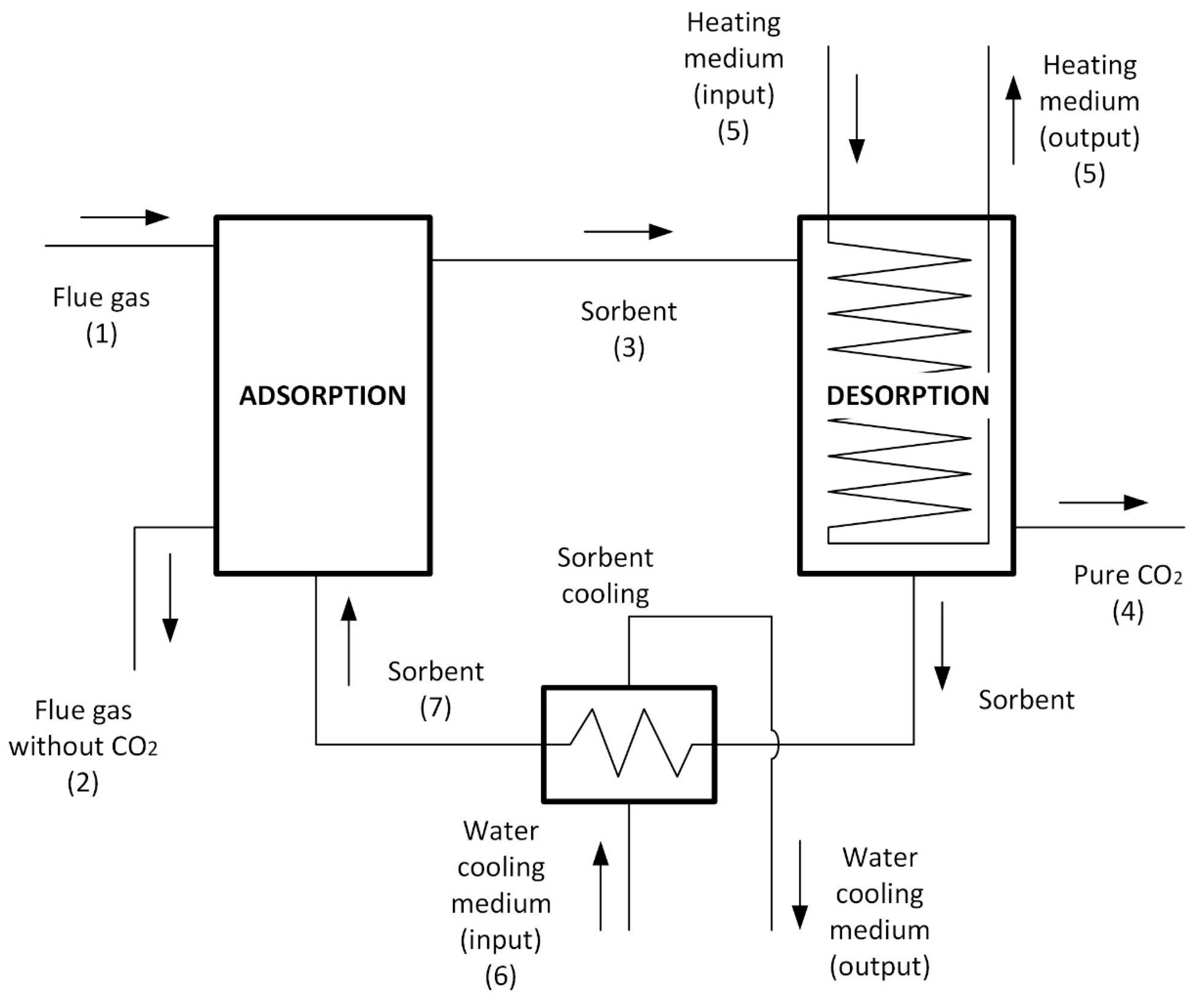
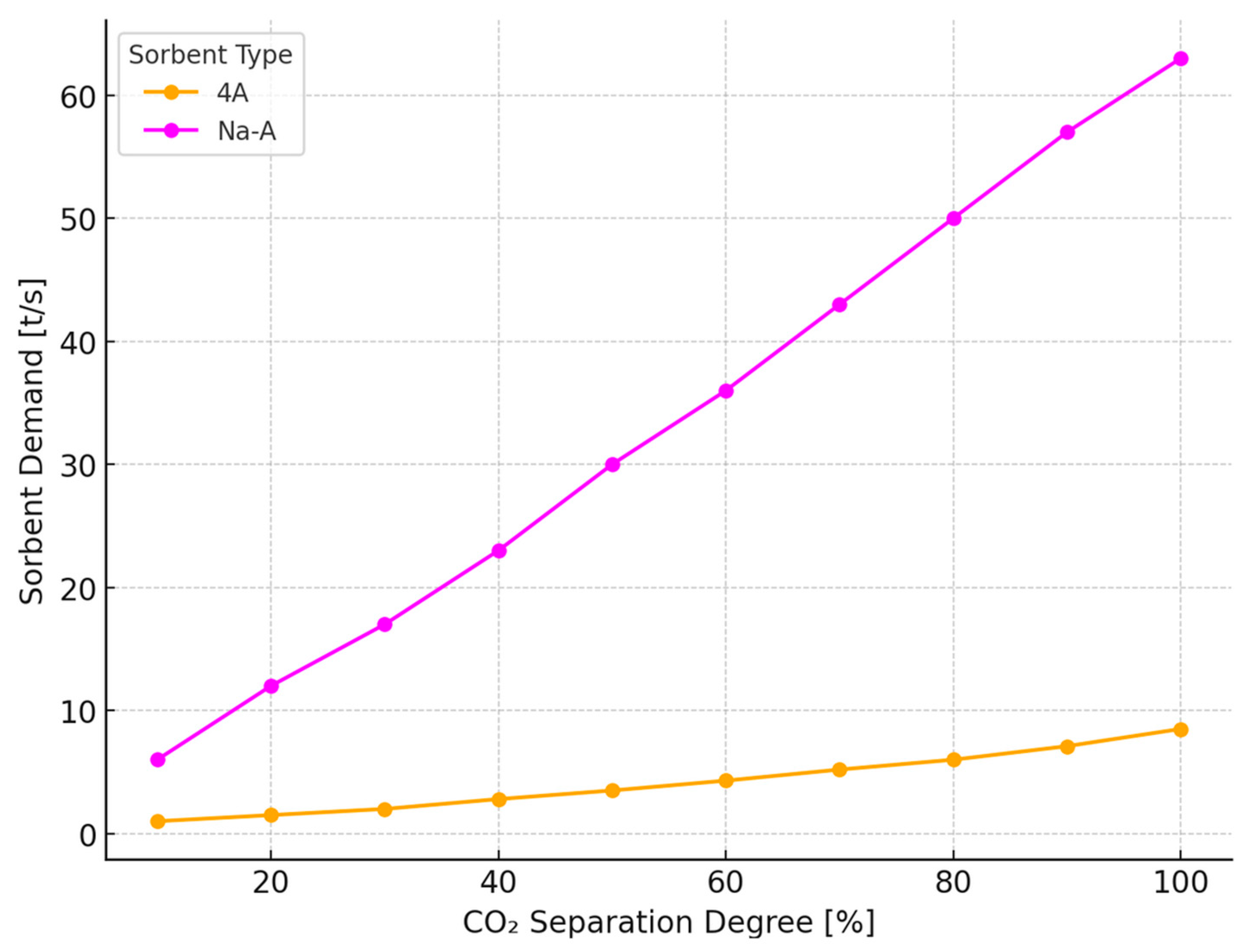
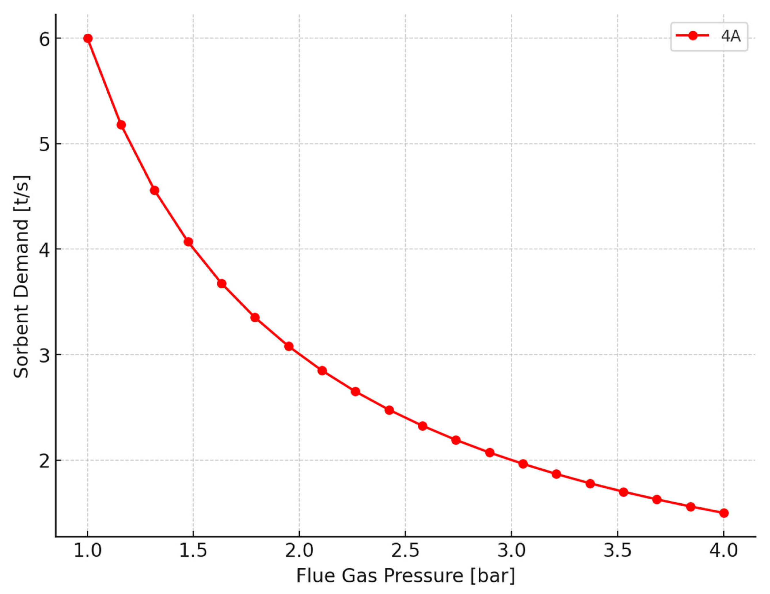
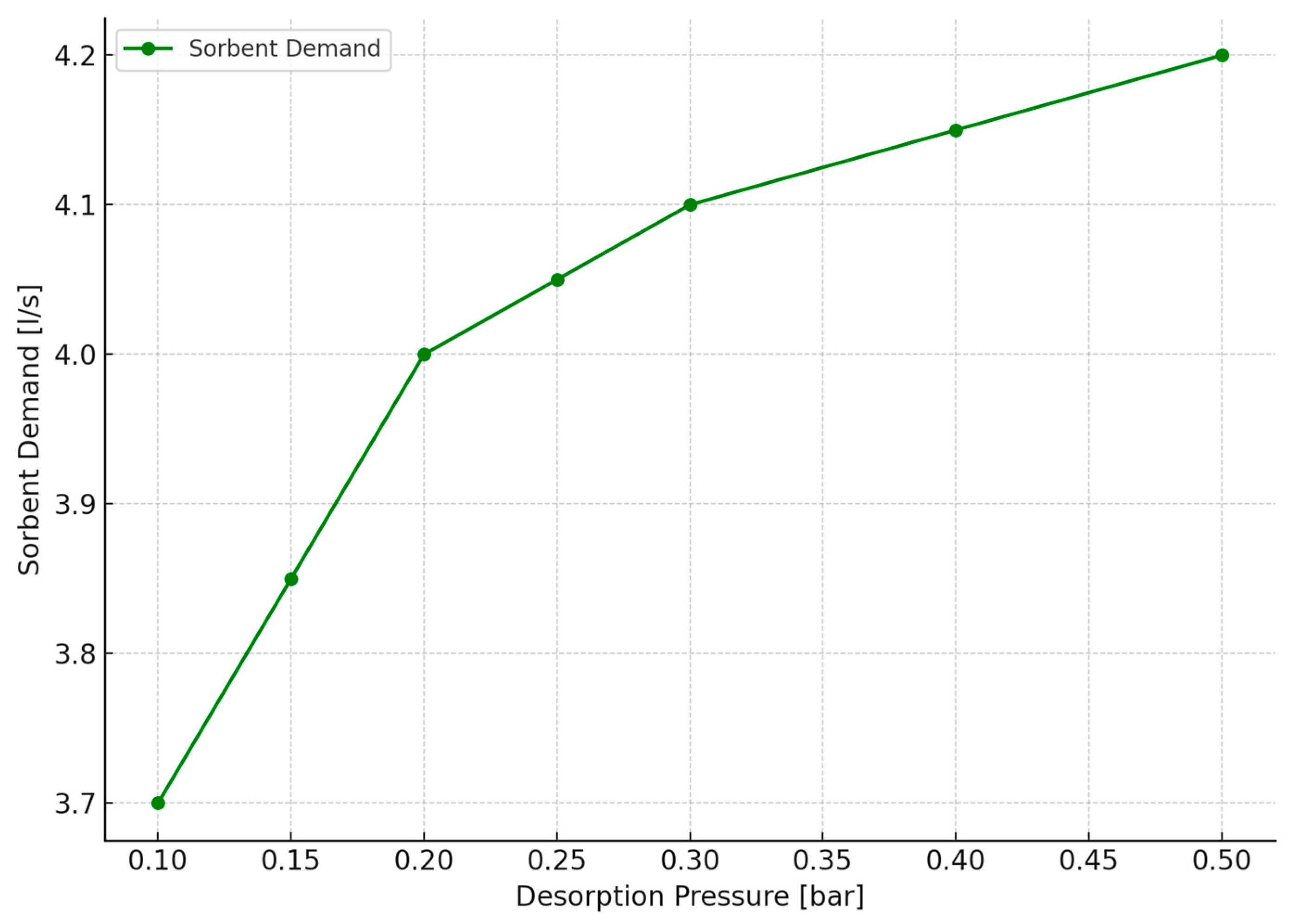
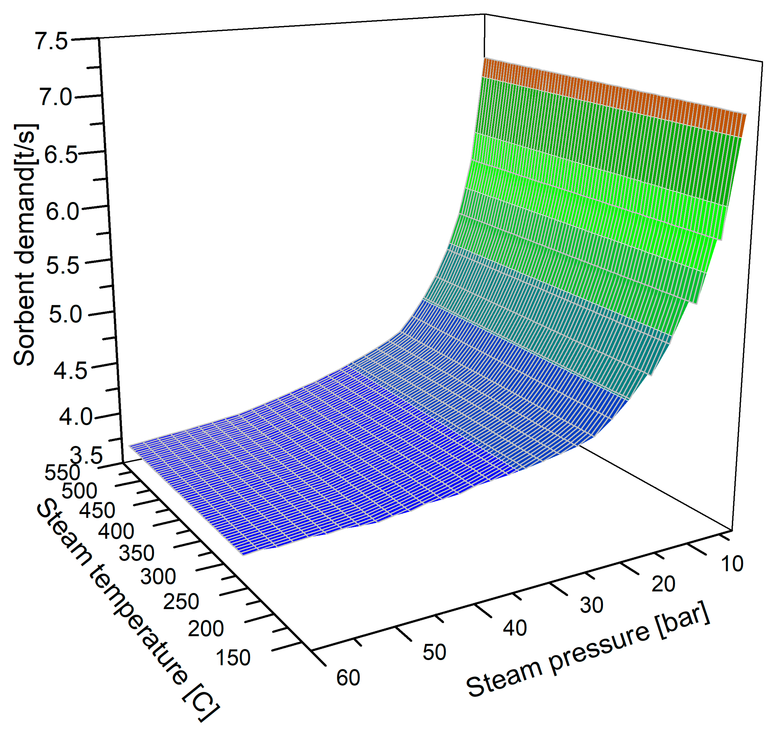
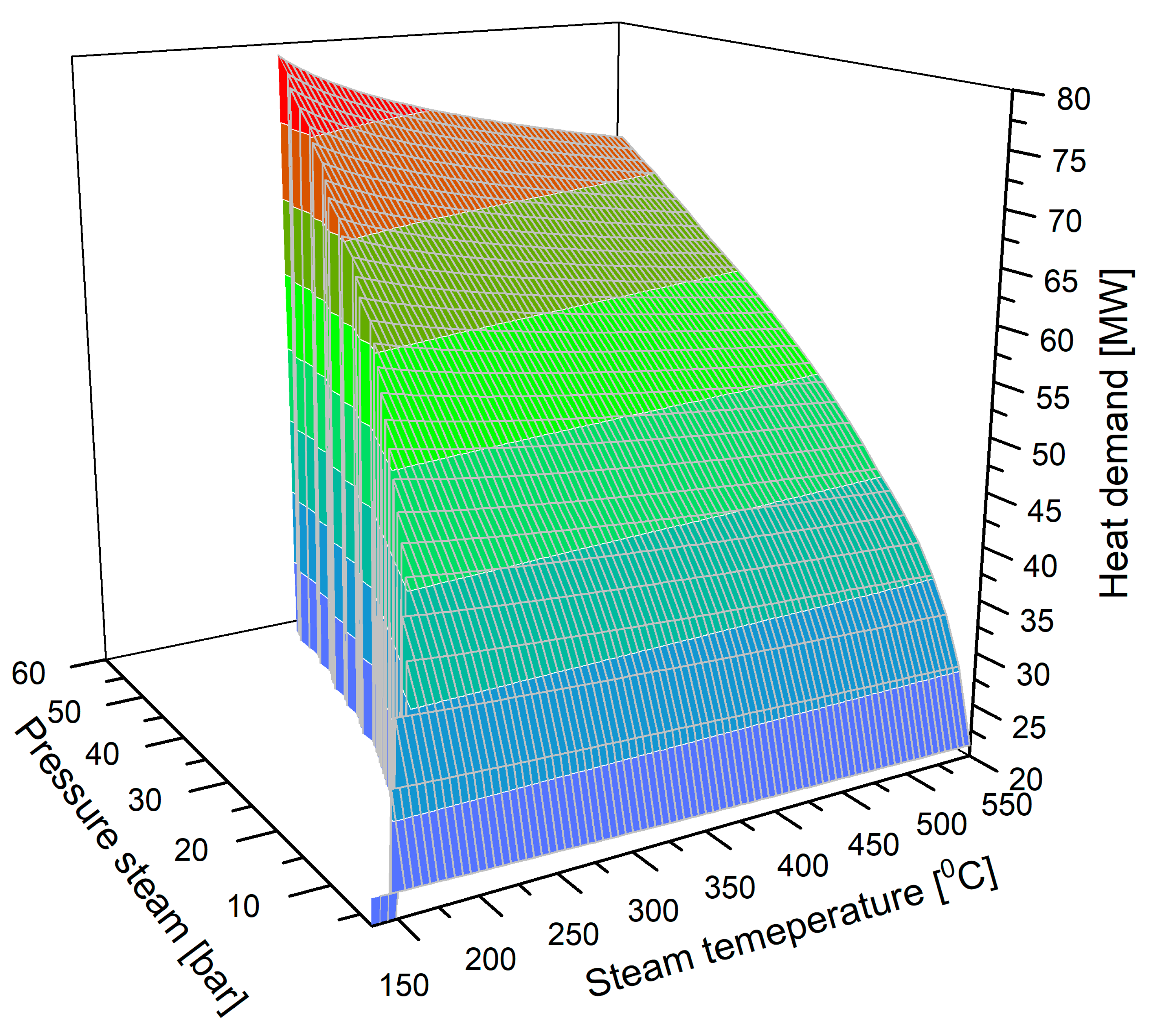
2.2. Analysis of the Operation of the CO2 Separation System of a PTSA Unit

According to the data contained in [43], increasing the temperature of the flue gas decreases the sorption capacity of the sorbents (e.g., 4A), which results in an increase in sorbent demand in the process of CO2 adsorption from flue gas. Therefore, it is advisable to run the adsorption process at the lowest possible flue gas temperature. In the reference block model, the flue gas reaches a temperature of t = 110 °C at p = 1.1 bar before entering the stack. This is the reason why this temperature was adopted as the optimum CO2 adsorption temperature for zeolite 4A. The effect of flue gas pressure on the adsorption process was also analysed. An increase in the pressure from 1.1 bar to approx. 4 bar (Figure 5) results in an approx. 80% decrease in the demand for sorbent 4A. However, such a high compression of flue gas is not energy-efficient as the cost of compression is very high in relation to the reduction in sorbent demand. Compressing the flue gas above the margin pressure (flue gas pressure above which the reduction in sorbent demand is less than 2%) is not energetically reasonable as the benefits gained from compressing the flue gas are inadequate in relation to the reduction achieved in sorbent demand. Based on the data obtained, the optimum pressure to carry out the adsorption process is determined, and the value of this pressure for zeolite 4A is p = 2.0 bar where a decrease in demand of 50% is observed compared with a pressure of 1.1 bar.
In the PTSA system, the process of desorption is carried out at a lower pressure and higher temperature than during the process of adsorption. The amount of carbon dioxide released corresponds to the difference in the adsorption capacity of sorbent 4A at the pressure and temperature of adsorption and desorption. The process of desorption was analysed for zeolite 4A in the pressure range between 0.15 bar and 0.5 bar. The range adopted corresponds to the proposed operating conditions of the PTSA pilot plant for CO2 capture at TEPCO’s Yokosuka Power Plant owned by Mitsubishi Heavy Industries [35]. Figure 6 shows the effect of desorption pressure on demand for sorbent 4A for a total flue gas flow of Q ˙ flue = 1000 kg/s at a CO2 separation rate of 100%.
Running the process of regeneration at 0.15 bar results in an approx. 8% reduction in sorbent 4A demand compared to a pressure of 0.5 bar. It was also assumed that the process of desorption (regeneration of sorbent 4A) would be carried out at 0.15 bar because it is at this pressure that the lowest demand for sorbent 4A is achieved. The next stage of the simulation testing is to analyse the influence of the parameters (pressure and temperature) of the heating medium, which in this case is bled steam, on the process of sorbent regeneration (desorption). According to the model assumptions, the heat given off by the heating medium is used to heat the sorbent and desorbed CO2 and is also consumed to cover the required heat for the desorption process. In order to carry out sorbent regeneration, steam was used, which varied in pressure from p = 3 bar to p = 60 bar and temperature from 140 °C to 550 °C (Figure 7); simulations in this pressure range were limited by the acceptable range of pressures and temperatures in the water steam cycle of power plants. The limits of the temperature and pressure ranges correspond to the minimum and maximum parameters of the steam from the bleeds of the turbine in the reference thermal cycle.
At a steam pressure of 60 bar and a desorption temperature of 280 °C, the demand for sorbent is the lowest because higher desorption temperatures increase the release of CO2, which improves the efficiency of the utilisation of the sorbent (Figure 7). For a steam pressure of 3 bar and a desorption temperature of 140 °C, the demand for sorbent increases by 50% compared to a pressure of 60 bar. The optimum desorption pressure for zeolite 4A is 20 bar where the process runs most efficiently where reducing the demand for sorbent at temperatures of 200–550 °C. It follows from the above analysis that the use of steam with higher parameters results in a reduction in the amount of sorbent for CO2 separation. At the same time, the use of steam with higher parameters results in an increase in the demand for heat required for the regeneration process (Figure 8). As the temperature increases from 140 °C to 550 °C, a reduction in heat demand is observed in the pressure range from 3 bar to 60 bar.
The average decrease in heat demand in this area is about 15% (corresponding to an energy cost of about 7 MWt). It follows from the data shown here that when the steam pressure is increased from 3 bar to 60 bar, the heat demand for the desorption process increases sevenfold for zeolite 4A. It was determined that steam with a pressure of 20 bar in the temperature range 200–550 °C is the most suitable for desorption because under these conditions the desorption process is about at 200 °C and the maximum heat demand is then approx. 50 MWt. However, after the desorption process (release of CO2 from zeolite 4A) the temperature of the sorbent is slightly lower than the temperature of the heating medium. After regeneration of sorbent 4A, the temperature is about 200 °C, which is too high for the adsorption process and must be reduced to approximately 110 °C using a cooling medium taken from the main cycle of steam turbine. In order to cool down the sorbent, condensate at the lowest possible temperature (approx. 30 °C) drawn from the thermal cycle of the power unit can be used. Based on the simulation, the operating parameters of the PTSA unit for CO2 capture from boiler flue gas were determined. The key operating conditions for the adsorption–desorption process are summarized in Table 3.

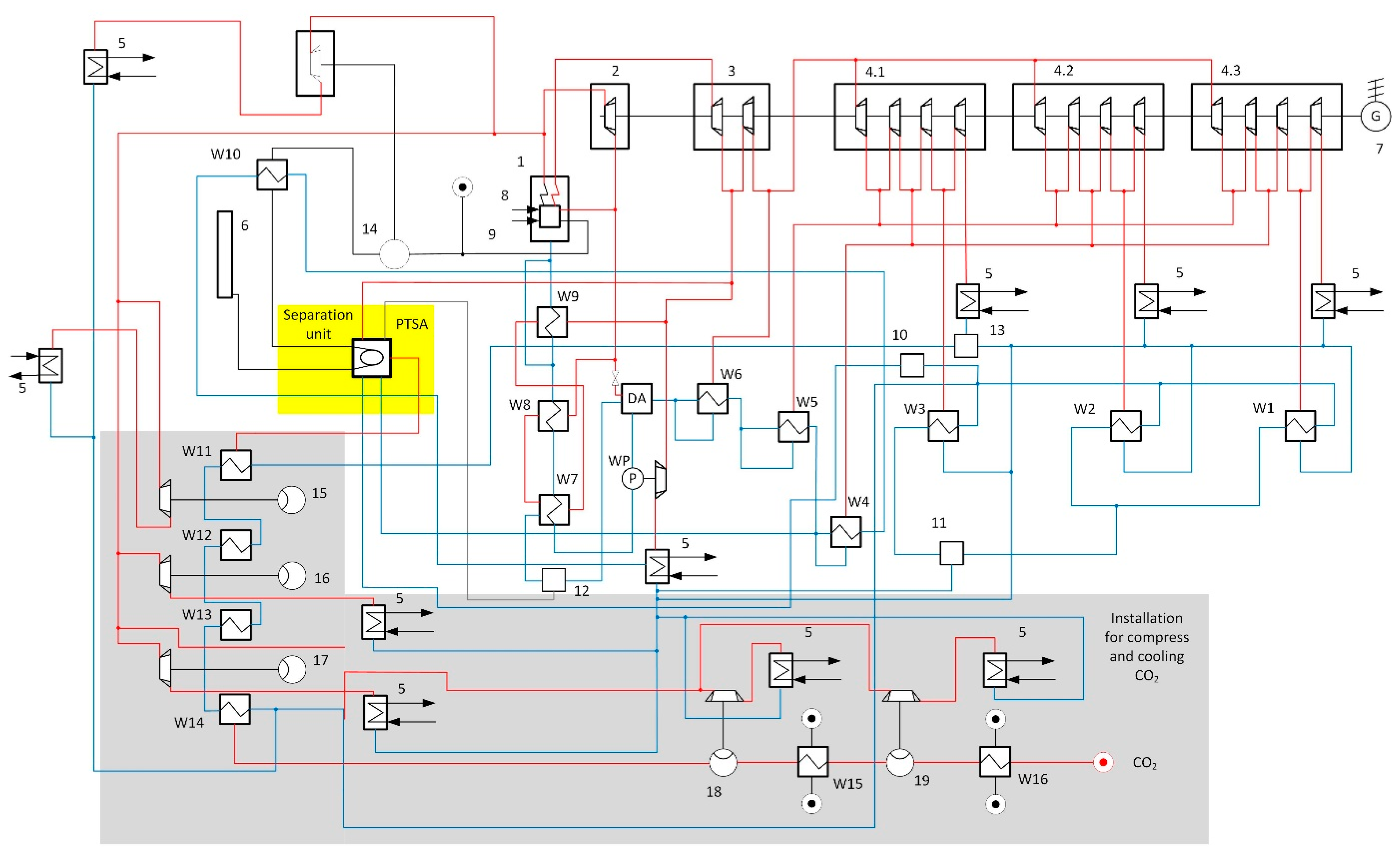
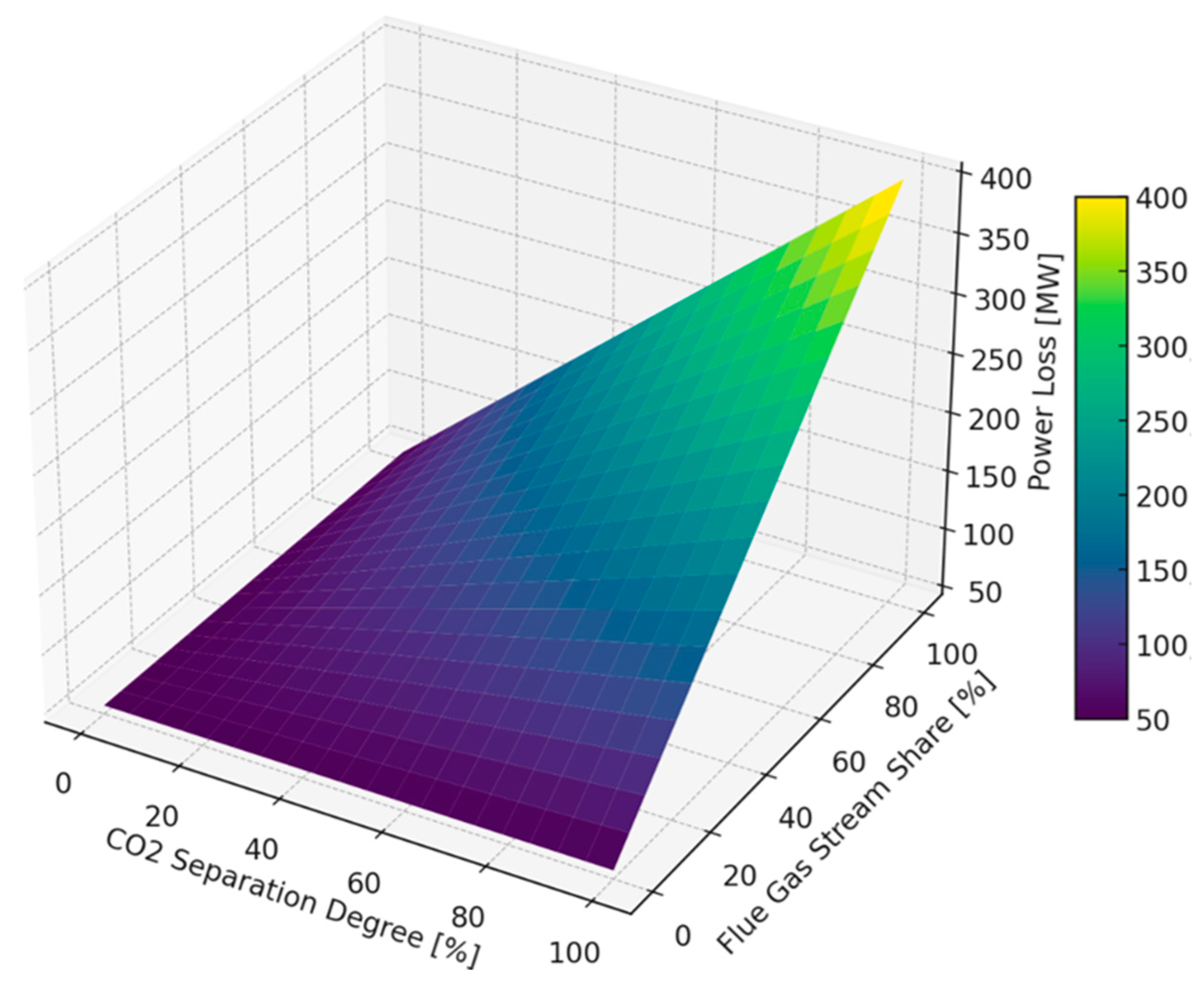
2.3. Analysis of the Integration of the CO2 Capture System into the Thermal Cycle of the Power Unit

An analysis of the integration of the CO2 capture system with the reference cycle was carried out for zeolite 4A. In this stage of the study, a model of the separation unit with zeolite 4A was integrated into the thermal cycle of a reference 830 MWe power unit (Figure 9). The simulation calculations investigated the impact of the boiler flue gas-CO2 separation unit together with the equipment for the technical implementation of carbon dioxide adsorption, desorption, and liquefaction on the efficiency and power output of the reference power unit. The analysis was carried out with different rates of CO2 separation from flue gas and for different flue gas flows routed to the PTSA unit. The following assumptions were made for the simulation tests:
Flue gas entering the separation system is free of sulphur and nitrogen oxides;
Flue gas is dry and dedusted;
For zeolite 4A, flue gas is introduced into the separation unit at a pressure of p = 2.0 bar and a temperature of t = 110 °C;
The source of heat required for the regeneration of zeolite 4A is steam with a pressure of p = 20 bar and a temperature in the range t = 200–550 °C;
Compression and cooling of the separated CO2 occurs.
The carbon dioxide released from the sorbent after the regeneration process in the gaseous state with a temperature of t = 207 °C and a pressure of p = 0.15 bar is discharged out of the PTSA unit. However, in order for it to be used in other industries or stored, it must be transported to its final destination in the liquid state. The separated carbon dioxide can be prepared for transport with multi-stage compression to 100 bar using five compressors driven by a live steam turbine, (15), (16), (17), (18), and (19). Before the first compression stage (15), carbon dioxide at 204 °C (the temperature of the CO2 leaving the capture unit) is cooled in exchanger (W11) to 35 °C, and then after each compression stage, the CO2 is cooled in exchangers (W12), (W13), and (W14) to 35 °C, and in the final stage, in exchangers (W15) and (W16) to 25 °C.
The power output of the unit and the efficiency of the reference cycle is influenced by the separation unit because in order to carry out the sorbent regeneration process, bled steam is used, and the amount of steam depends on the demand for sorbent, which increases with the rate of separation and the flue gas flow routed to the capture system. However, in order for the separation process to take place at an optimum pressure of 2.0 bar (for zeolite 4A), the flue gas pressure must be increased above 1.1 bar. For this, a compressor driven by a live steam turbine is used in a like manner as the compressor for carbon dioxide compression. The PTSA unit and the devices for preparing flue gas (prior to entering the PTSA unit) and carbon dioxide liquefaction force an increased steam intake, thereby causing a decrease in electrical power output at the generator terminals, which consequently translates into a decrease in the efficiency of the power unit cycle. As mentioned earlier, cooling of the flue gas before it enters the separation unit can be carried out using heat exchanger (W10), and the cooling medium can be water with parameters p = 15 bar and t = 50 °C taken from the thermal cycle of the unit. However, as far as the cooling of carbon dioxide is concerned, this can be performed by taking the condensate from the thermal cycle (p = 13 bar, t = 30 °C) and passing it through a system with four exchangers, after which the condensate can be fed back into the main condensate cycle. However, in order for the carbon dioxide cooling process to work for a larger flow rate, water drawn from the main condensate flow must be diverted to the two exchangers and then returned to the main cycle after heating. The other exchangers for CO2 cooling must be supplied with external coolant. However, the use of either method of CO2 cooling does not significantly improve the efficiency of the power unit cycle.
The results of the simulation calculations in Figure 10 and Figure 11 show that with 100% CO2 separation for the total flue gas flow, a decrease of as much as 358 MWe in the power output of the unit and a decrease of 15.4% in the efficiency of the reference cycle are observed. In this case, it is the total decrease, i.e., taking into account the impact of the separation system, the flue gas compression system, and the CO2 compression system on the operation of the power unit. It follows from the data obtained (Table 4) that the separation of carbon dioxide from the maximum flue gas flow, taking into account all the equipment necessary for the technical implementation of the process, is very energy-intensive, thus causing a very large decrease in the power output and efficiency of the unit.
The calculated heat demand for the desorption process in the analysed PTSA system using zeolite 4A is approximately 0.29 MJ/kg of CO2. This value results from the applied thermal power of 50 MWt required for the regeneration of the sorbent at the specified operating conditions (adsorption at 2.0 bar and 110 °C; desorption at 0.15 bar and 212 °C).
When comparing this result to the data presented [37] for traditional pressure swing adsorption (PSA) systems using zeolite 5A, where the reported heat demand is approximately 0.56 MJ/kg of CO2, the PTSA system analysed here demonstrates a significantly lower energy requirement for sorbent regeneration. This reduction in energy demand can be attributed to the combined use of both pressure and temperature swings in PTSA, which enhances desorption efficiency compared to pressure-only swing methods like PSA. This difference is also consistent with the general trend observed in the literature, where temperature swing or combined pressure–temperature swing adsorption (PTSA) processes tend to require lower thermal input for regeneration than pressure swing alone, especially at higher desorption temperatures, where the sorption capacity of the zeolite significantly decreases, facilitating easier CO2 release.

3. Conclusions

Based on the analysis performed and the results of the simulation calculations concerning the system of CO2 capture in power units, several key conclusions can be drawn. First of all, the complete separation of CO2 from the flue gas produced by a unit with a rated power output of 830 MWe is technically possible but involves a significant decrease in the efficiency of the thermal cycle and a high energy demand. This is so because the process of capturing and liquefying CO2 requires significant energy input, which translates into an approx. 358 MWe decrease in the power output of the unit and a 15.4% reduction in its efficiency. This level of energy loss makes complete CO2 capture not economically viable under real-world industrial conditions, limiting the possibility of fully eliminating emissions of this greenhouse gas.
A key factor to reduce energy loss is the use of heat generated in the CO2 sequestration process, which can be returned to the thermal cycle, thus significantly improving the energy balance.
The application of adsorptive separation methods, in particular those using synthetic zeolite 4A, turns out to be the most effective. Zeolite 4A is characterised by low sorbent consumption compared to other materials analysed, such as sodalite or zeolite synthesised from fly ash. The demand for zeolite 4A is up to six times lower compared to zeolite synthesised from fly ash, making it the most efficient sorbent in the sorbent group analysed. At the same time, zeolites derived from fly ash, which is a by-product of fossil fuel combustion, can be an alternative. Their use allows for the management of power plant waste, which can reduce the cost of CO2 separation and further contribute to environmentally friendly measures.
Correct parameters in the processes of adsorption and desorption are crucial to the efficiency of the system. The adsorption process for zeolite 4A works best at 2.0 bar and 110 °C. Desorption, on the other hand, should be carried out at a pressure of 0.15 bar and a temperature of 204 °C, which minimises the demand for sorbent and thermal energy. Another important aspect is a reduction in the flue gas compression pressure, because high pressures are not energy-efficient and the benefits of reducing sorbent consumption are disproportionate to the costs incurred.
In the case of CO2 removal from the flue gas of a coal-fired boiler, the energy demand for solvent regeneration in the CANSOLV absorption process is approximately 2.4 MJ/kg of CO2.
In comparison, the calculated heat demand for the desorption process in the analysed PTSA system using zeolite 4A in this case is significantly lower, at approximately 0.29 MJ per kg of CO2. This represents almost a 90% reduction in the thermal energy requirement compared to the CANSOLV absorption technology.
The lower heat demand of the PTSA process results from the use of solid sorbents and the combination of pressure and temperature swings for regeneration, which eliminates the need for solvent heating and vaporisation, characteristic of absorption methods like CANSOLV. However, it should be noted that while absorption technologies such as CANSOLV are commercially proven and widely implemented in industrial CO2 capture, PTSA remains at the pilot or laboratory scale, and its effectiveness under full-scale conditions requires further validation.
Thus, while PTSA offers promising energy efficiency advantages over traditional solvent-based methods, absorption processes currently hold an advantage in terms of technological maturity and industrial readiness.
The integration of the CO2 capture system into the thermal cycle of the power unit involves the use of bled steam for sorbent regeneration, which contributes to a decrease in the power of the unit. Flue gas cooling and CO2 compression further increase the load on the system, requiring careful design of the systems that support the separation process. Such a solution can make a significant contribution to reducing greenhouse gas emissions while supporting sustainability and environmental protection measures in line with the guidelines of the European Union.

Author Contributions

Conceptualization, K.S.; methodology, K.S.; formal analysis, Ł.M.; writing—original draft preparation, K.S. and Ł.M.; writing—review and editing, K.S. and Ł.M.; visualisation, Ł.M.; supervision, K.S.; project administration, Ł.M.; funding acquisition, K.S. All authors have read and agreed to the published version of the manuscript.

Funding

This research was partially supported by the Ministry of Science and Higher Education, Poland, grant AGH number 16.16.210.476.

Data Availability Statement

Data is contained within the article.

Conflicts of Interest

The authors declare no conflicts of interest.

Nomenclature

Symbols
m ˙ Mass flow [kg/s]
pPressure [bar]
tTemperature [°C]
hEntalphy [J/kg]
QSorption heat [kJ/kgCO2]
Q ˙ Heat transfer [W]
aSorption capacity [kg/kg]
XMass share of the exhaust gas components [kg/kg]
p Temperature drop [°C]
t Pressure drop [bar]
η Power plan efficiency [-]
PPower [W]
Subscripts
1Exhaust gas
2Clear carbon dioxide
3Exhaust gas without CO2
4Sorbent regeneration steam inlet
5Sorbent regeneration steam outlet
6PTSA cooling water inlet
7PTSA cooling water outlet
8Sorbent after desorption
9Cooled sorbent after desorption
10Sorbent before desorption
aAdsorption
dDesorption
transHeat transferred to the sorbent during adsorption
sorbSorbent
tr1Heating the sorbent during desorption
tr2Heating the CO2 during desorption
spExhaust gas
gSorbent regeneration steam
chPTSA cooling water
el,grosstotal electricity
fuelchemical power
el,own cons.electricity consumption of auxiliary equipment

References

  1. Filonchyk, M.; Peterson, M.P.; Zhang, L.; Hurynovich, V.; He, Y. Greenhouse gases emissions and global climate change: Examining the influence of CO2, CH4, and N2O. Sci. Total Environ. 2024, 935, 173359. [Google Scholar] [CrossRef] [PubMed]
  2. Gaikwad, R.W.; Gudadhe, M.D.; Bhagat, S.L. Carbon dioxide capture, tolerance and sequestration using microalgae—A review. Int. J. Pharm. Chem. Biol. Sci. 2016, 6, 345–349. [Google Scholar]
  3. Tarkowski, R.; Uliasz-Misiak, B.; Tarkowski, P. Storage of hydrogen, natural gas, and carbon dioxide—Geological and legal conditions. Int. J. Hydrogen Energy 2021, 46, 20010–20022. [Google Scholar] [CrossRef]
  4. IPCC SRCCS. Special Report of the Intergovernmental Panel of Climate Change on Carbon Capture and Storage; Cambridge University Press: Cambridge, UK, 2007. [Google Scholar]
  5. Kotowicz, J.; Janusz, K. Methods for reducing CO2 emissions from energy processes. Energy Market. 2007, 41, 171–192, ISSN 1425-5960. [Google Scholar]
  6. Prajapati, M.; Thesia, D.; Thesia, V.; Rakholia, R.; Tailor, J.; Patel, A.; Pardiwala, J.M.; Shah, M. Carbon capture, utilization, and storage (CCUS): A critical review towards carbon neutrality in India. Case Stud. Chem. Environ. Eng. 2024, 10, 100770. [Google Scholar] [CrossRef]
  7. Construction of 833 MW Power Unit at BOT-Elektrownia Bełchatów S.A.: Summary of the Environmental Impact Statement; 2006. Available online: https://www.google.com/url?sa=t&source=web&rct=j&opi=89978449&url=https://www.ebrd.com/english/pages/project/eia/25438e.pdf&ved=2ahUKEwiyhbyKrf-MAxW3KhAIHc32D8EQFnoECBAQAQ&usg=AOvVaw3SgGxsFAmTlmHgERaNTgzL (accessed on 1 January 2006).
  8. Dreszer, K.; Solny, L.W. Reduction of CO2 emissions in the energy sector: Possible technology pathways. Energy Policy. 2008, 11, 117–129. [Google Scholar]
  9. CO2Europipe. Towards a Transport Infrastructure for Large-Scale CCS in European Collaborative Project; D4.4.2 WP4.4 Report, Belchatow Power Plant—Test Case; CO2Europipe: Utrecht, The Netherlands, 2009; Available online: https://www.co2europipe.eu/Publications/D4.4.2%20-%20Belchatow%20Power%20Plant%20-%20test%20case.pdf (accessed on 1 January 2025).
  10. Our World in Data. CO2 and Greenhouse Gas Emissions. Available online: https://ourworldindata.org/co2-and-greenhouse-gas-emissions (accessed on 1 January 2025).
  11. Davoodi, S.; Al-Shargabi, M.; Wood, D.A.; Rukavishnikov, V.S.; Minaev, K.M. Review of technological progress in carbon dioxide capture, storage, and utilization. J. Nat. Gas Sci. Eng. 2023, 117, 205070. [Google Scholar] [CrossRef]
  12. IPCC. Summary for policymakers. In Climate Change 2023: Synthesis Report. Contribution of Working Groups I, II and III to the Sixth Assessment Report of the Intergovernmental Panel on Climate Change; Core Writing Team, Lee, H., Romero, J., Eds.; IPCC: Geneva, Switzerland, 2023; pp. 1–34. [Google Scholar] [CrossRef]
  13. McLaughlin, H.; Littlefield, A.A.; Menefee, M.; Kinzer, A.; Hull, T.; Sovacool, B.K.; Bazilian, M.D.; Kim, J.; Griffiths, S. Carbon capture utilization and storage in review: Sociotechnical implications for a carbon reliant world. Renew. Sustain. Energy Rev. 2023, 177, 113215. [Google Scholar] [CrossRef]
  14. Leung, D.Y.C.; Caramanna, G.; Maroto-Valer, M.M. An overview of current status of carbon dioxide capture and storage technologies. Renew. Sustain. Energy Rev. 2014, 39, 426–443. [Google Scholar] [CrossRef]
  15. Mazurkiewicz, M. Methods of CO2 separation and capture. Energy Policy 2005, 8, 527–538. [Google Scholar]
  16. Czakiert, T.; Nowak, W.; Bis, Z. Combustion in oxygen-modified atmospheres as a development direction for CWF boilers. Energetics Probl. Power Eng. Fuel Energy Econ. 2008, 10, 713–718, ISSN 0013-7294. [Google Scholar]
  17. Alami, A.H.; Alasad, S.; Ali, M.; Alshamsi, M. Investigating algae for CO2 capture and accumulation and simultaneous production of biomass for biodiesel production. Sci. Total Environ. 2021, 759, 143529. [Google Scholar] [CrossRef]
  18. Lu, G.; Wang, Z.; Bhatti, U.H.; Fan, X. Recent progress in carbon dioxide capture technologies: A review. Clean Energy Sci. Technol. 2023, 1, 32. [Google Scholar] [CrossRef]
  19. Warych, J. Gas Cleaning Processes: Design and Computational Problems; Warsaw University of Technology Press: Warsaw, Poland, 2000; p. 466. ISBN 8372071128. [Google Scholar]
  20. Cavalcante, C.L. Industrial adsorption separation processes: Fundamentals, modeling, and applications. Lat. Am. Appl. Res. 2000, 30, 357–364. [Google Scholar]
  21. Feron, P. Absorption-Based Post-Combustion Capture of Carbon Dioxide; Woodhead Publishing: Cambridge, UK, 2016. [Google Scholar]
  22. Xu, X.; Chunshan, S.C.; Miller, G.B.; Scaroni, W.A. Adsorption separation of carbon dioxide from flue gas of natural gas-fired boiler by a novel nanoporous molecular basket adsorbent. Fuel Process. Technol. 2005, 86, 1457–1472. [Google Scholar] [CrossRef]
  23. Hong, W.Y. A techno-economic review on carbon capture, utilisation and storage systems for achieving a net-zero CO2 emissions future. Carbon Capture Sci. Technol. 2022, 3, 100044. [Google Scholar] [CrossRef]
  24. Göttlicher, G.; Pruschek, R. Comparison of CO₂ removal systems for fossil-fuelled power plant processes. Energy Convers. Manag. 1997, 38, S173–S178. [Google Scholar] [CrossRef]
  25. Chmielniak, T.; Ziębik, A. (Eds.) Thermal Cycles of Supercritical Coal-Fired Units: Collective Work; Silesian University of Technology Press: Gliwice, Poland, 2010; p. 458. ISBN 978-83-7335-680-1. [Google Scholar]
  26. Gomes, V.G.; Yee, K.W.K. Pressure swing adsorption for carbon dioxide sequestration from exhaust gases. Sep. Purif. Technol. 2002, 28, 161–171. [Google Scholar] [CrossRef]
  27. Agarwal, A. Advanced Strategies for Optimal Design and Operation of Pressure Swing Adsorption Processes. Ph.D. Thesis, Carnegie Mellon University, Pittsburgh, PA, USA, 2010. Available online: https://numero.cheme.cmu.edu/content/thesis/sree_thesis.pdf (accessed on 1 January 2011).
  28. Majchrzak-Kucęba, I.; Nowak, W. Studies of CO2 removal from flue gases using various types of zeolites. In Proceedings of the 2nd International Conference on Contemporary Problems of Thermal Engineering, Gliwice, Poland, 23–26 September 2004. [Google Scholar]
  29. Ahmad, M.; Dutta, A. Recent advances in pressure swing adsorption for carbon dioxide capture. Renew. Sustain. Energy Rev. 2023, 182, 113417. [Google Scholar] [CrossRef]
  30. Chiang, A.S.T.; Hong, M.C. Radial flow rapid pressure swing adsorption. Adsorption 1995, 1, 153–164. [Google Scholar] [CrossRef]
  31. Suzuki, M.; Susuk, T.; Sakoda, A.; Izumi, J. Piston-driven ultra-rapid pressure swing adsorption. Adsorption 1996, 2, 111. [Google Scholar] [CrossRef]
  32. Grande, C.A.; Ribeiro, R.P.P.L.; Rodrigues, A.E. Electric Swing Adsorption for CO2 removal from flue gases. Int. J. Greenh. Gas Control. 2008, 2, 194–202. [Google Scholar] [CrossRef]
  33. Chevrel, C.; de Joannis, P.; Castel, C.; Authier, O. Modeling of CO2 capture by electro-swing reactive adsorption from low-concentration streams. Clean Technol. 2025, 7, 18. [Google Scholar] [CrossRef]
  34. Ishibashi, M.; Otake, K.; Kanamori, S. Study on CO2 removal technology from flue gas of thermal power plants by physical adsorption methods. Greenh. Gas Control Technol. 1999, 37, 929–933. [Google Scholar]
  35. European Commission. Proposal for a Decision of the European Parliament and of the Council on the Effort of Member States to Reduce Their Greenhouse Gas Emissions to Meet the Community’s Greenhouse Gas Emission Reduction Commitments Up to 2020. COM(2008) 17 Final, Brussels, Belgium, 2008. Available online: https://eur-lex.europa.eu/legal-content/EN/TXT/?uri=celex:52008PC0017 (accessed on 1 January 2008).
  36. Warych, J. Gas Cleaning: Processes and Equipment; Scientific and Technical Publishers: Warsaw, Poland, 1998; ISBN 8320423058. [Google Scholar]
  37. Riboldi, L.; Bolland, O. Evaluating Pressure Swing Adsorption as a CO2 separation technique in coal-fired power plants. Int. J. Greenh. Gas Control 2015, 39, 1–16. [Google Scholar] [CrossRef]
  38. Wawryńczak, D.; Majchrzak-Kucęba, I.; Srokosz, K.; Kozak, M.; Nowak, W.; Zdeb, J.; Smółka, W.; Zajchowski, A. The Pilot Dual-Reflux Vacuum Pressure Swing Adsorption Unit for CO2 Capture from Flue Gas. Sep. Purif. Technol. 2019, 209, 560–570. [Google Scholar] [CrossRef]
  39. US. Department of Energy, National Energy Technology Laboratory (NETL). Cost and Performance Baseline for Fossil Energy Plants. Volume 1: Bituminous Coal and Natural Gas to Electricity; DOE/NETL-2023/4320; NETL: Pittsburgh, PA, USA, 2022.
  40. Sztekler, K.; Kalawa, W.; Nowak, W.; Stefański, S.; Krzywański, J.; Grabowska, K.; Mika, Ł. Possibility of use adsorption chillers for increase efficiency in conventional power Plant. In Proceedings of the EPJ Web of Conferences, Venice, Italy, 13–17 May 2019; Volume 213, p. 02082. [Google Scholar] [CrossRef]
  41. Majchrzak-Kucęba, I. Study on the Removal and Utilization of Carbon Dioxide from Boiler Flue Gases Using Zeolites. Ph.D. Thesis, Czestochowa University of Technology, Czestochowa, Poland, 26 April 2001. [Google Scholar]
  42. Wawryńczak, D.; Majchrzak-Kucęba, I.; Nowak, W. Possibilities of Using the Adsorption Method for CO2 Removal from Boiler Flue Gases. Sci. Pap. Rzesz. Univ. Technol. Mech. 2014, 86, 285–293. [Google Scholar]
  43. Mulgundmath, V.; Tezel, F.H. Optimisation of carbon dioxide recovery from flue gas in a TPSA system. Adsorption 2010, 16, 587–598. [Google Scholar] [CrossRef]
  44. Suchecki, T. Zeolites from Fly Ash: Production and Applications in Environmental Engineering; Ossolineum Publishing House: Wrocław, Poland, 2005. [Google Scholar]
  45. Majchrzak, A. Testing and Optimization of Solid Sorbents for CO2 Capture from Flue Gas. Ph.D. Thesis, AGH University of Science and Technology, Kraków, Poland, 2016. [Google Scholar]
Figure 1. Diagram of the reference of power plant model.
Energies 18 02387 g001
Figure 2. Operating diagram of a PTSA unit for CO2 separation.
Energies 18 02387 g002
Figure 3. Sorption capacity as a function of partial pressure of CO2: (A) zeolite 4A and (B) Zeolite Na-A [41,45].
Energies 18 02387 g003
Figure 4. Sorbent demand as a function of CO2 separation rate.
Energies 18 02387 g004
Figure 5. Effect of flue gas pressure on demand for sorbent 4A.
Energies 18 02387 g005
Figure 6. Effect of desorption pressure on demand for sorbent 4A.
Energies 18 02387 g006
Figure 7. Effect of steam parameters on demand for sorbent 4A.
Energies 18 02387 g007
Figure 8. Effect of steam parameters on demand for heat for zeolite 4A.
Energies 18 02387 g008
Figure 9. Schematic diagram of a reference unit model integrated with a CO2 capture unit.
Energies 18 02387 g009
Figure 10. Decrease in power of the unit as a function of CO2 separation rate and flue gas flow rate.
Energies 18 02387 g010
Figure 11. Decrease in efficiency of the unit as a function of CO2 separation rate and flue gas flow rate.
Energies 18 02387 g011
Table 1. Adsorbents and their general characteristics [22].
AdsorbentCharacteristicsApplication
Activated carbonHydrophobic properties; adsorption of organic compounds from air and water; low cost compared to other adsorbents; difficulty in regeneration; attrition; blocking pores.Removal of organic pollutants
Carbon molecular sieves (CMSs)Separation based on different particle diffusivity; selective adsorption of O2 only.Production of N2 from air
Silica gelHydrophilic adsorbent with high capacity; high sorption efficiency; incapable of removing trace amounts of water.Gas drying, removal of hydrocarbons to a low extent
Activated aluminaHydrophilic adsorbent with high capacity; high sorption efficiency; does not remove trace amounts of water.Gas drying
Zeolite molecular sieves (ZMSs)Hydrophilic properties; polar; regular pores; high adsorption selectivity; separation based on polarity and spatial structure of compounds.Separation of air components and other mixtures, dewatering
SilicaliteHydrophobic adsorbent with adsorption characteristics similar to activated carbon; burns more easily than activated carbon and is more costly in comparison therewith.Removal of organic compounds from gases
Adsorbent polymersOrdinary styrene–divinylbenzene copolymers; have good mechanical properties, minimising abrasion and erosion; more costly compared to activated carbon.Removal of organic compounds from gases
Non-regenerative adsorbentsSelectively reactive; able to remove trace contaminants; economic use at low contaminant concentrations and removal of less than 4 kg/hour.Removal of contaminants with low concentrations, such as H2S, SO2, and others from gases
BiosorbentsBiochemically active material deposited on a porous support; no regeneration is necessary when using this adsorbent; low sorption capacity compared with other sorbents. Removal of organic compounds from gases
Table 2. Basic parameters of the reference cycle.
Power output PG830MW
Fresh steam pressure266bar
Fresh steam temperature554°C
Fresh steam mass flow rate625kg/s
Reheated steam pressure54bar
Reheated steam temperature582°C
Efficiency of the reference cycle45.1%
Feed water temperature275°C
Mass flow rate of boiler flue gas1000kg/s
Mass flow rate of CO2170kg/s
Table 3. Parameters of the adsorption–desorption process.
Conditions of CO2 separationSorbent
Zeolite 4A
Selected parameters of the flue gasp = 2.0 bar
t = 110 °C
Selected parameters of the heating steamp = 20 bar
t = 200–550 °C
Pressure of desorptionp = 0.15 bar
Table 4. Basic parameters of the system for separation of CO2 from 100% flue gas flow at 100% separation rate.
ParametersZeolite 4A
Power input to the flue gas compressor110 MW
Demand for the sorbent4200 kg/s
Adsorption parametersp = 2.0 bar
t = 110 °C
Desorption parametersp = 0.15 bar
t = 212 °C
Thermal power for the desorption process [MWt]50 MWt
Total decrease in power output of the unit358 MWe
Total decrease in cycle efficiency15.4%
Power demand for CO2 compressors90 MW
Disclaimer/Publisher’s Note: The statements, opinions and data contained in all publications are solely those of the individual author(s) and contributor(s) and not of MDPI and/or the editor(s). MDPI and/or the editor(s) disclaim responsibility for any injury to people or property resulting from any ideas, methods, instructions or products referred to in the content.

