
Multi-Frequency Solar Rectenna Design for Hybrid Radio Frequency–Solar Energy Harvester


Abstract
1. Introduction
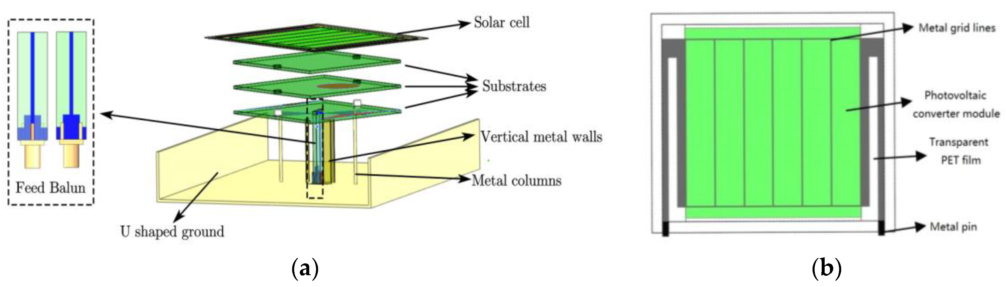
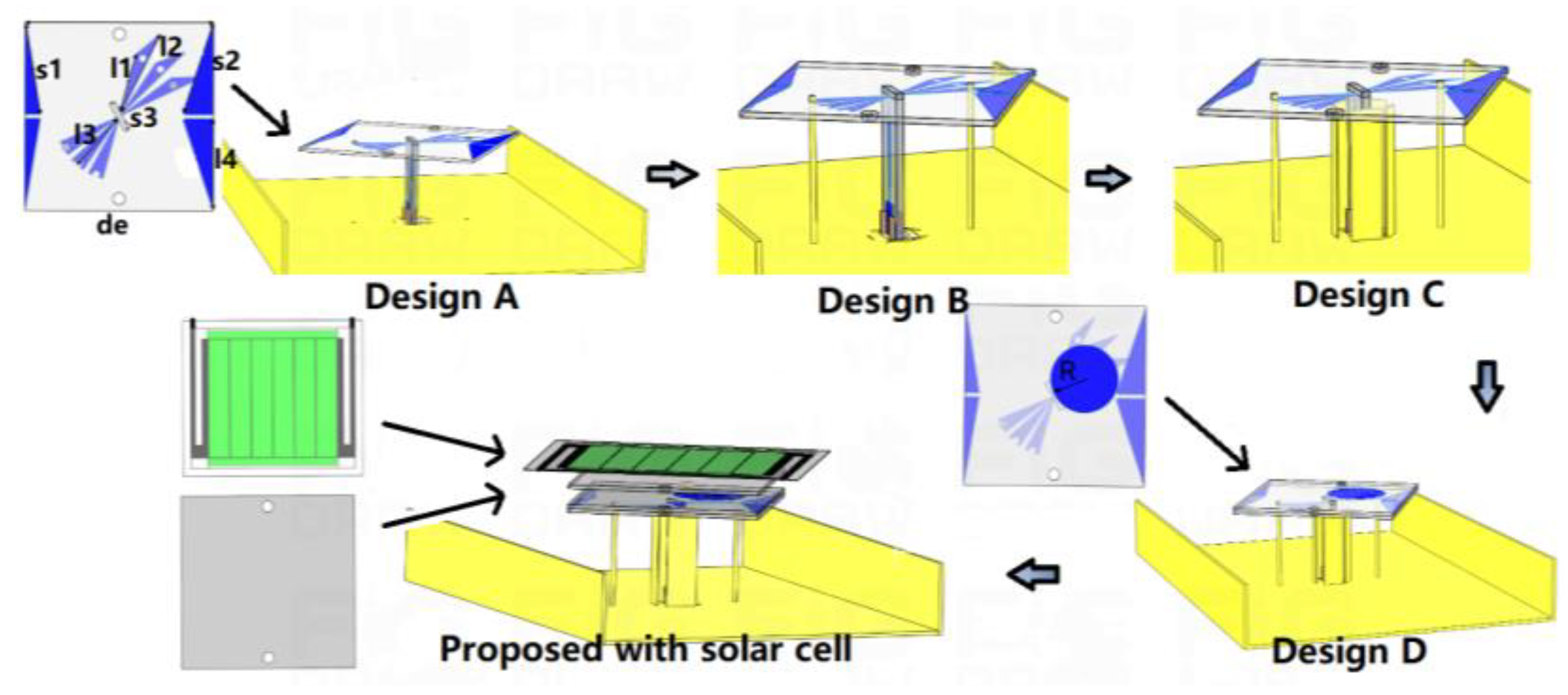
2. Solar Antenna Design
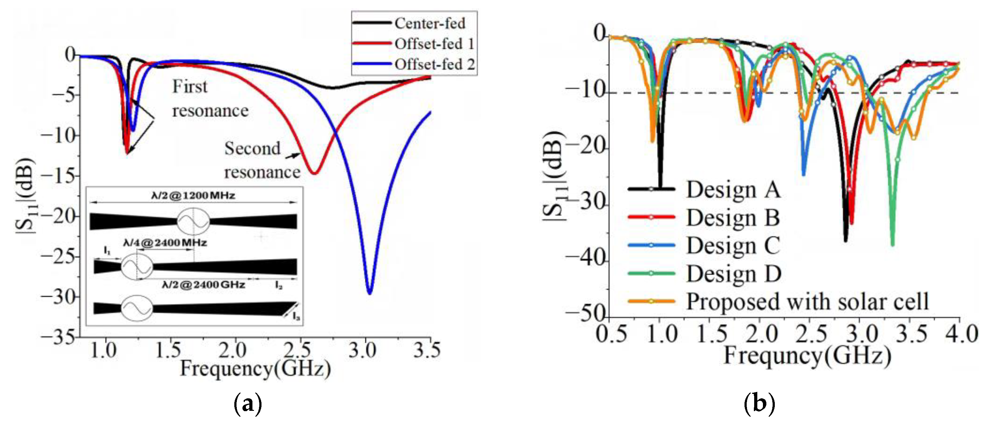
2.1. Quad-Band OCFD Antenna
2.2. Solar Cell Model
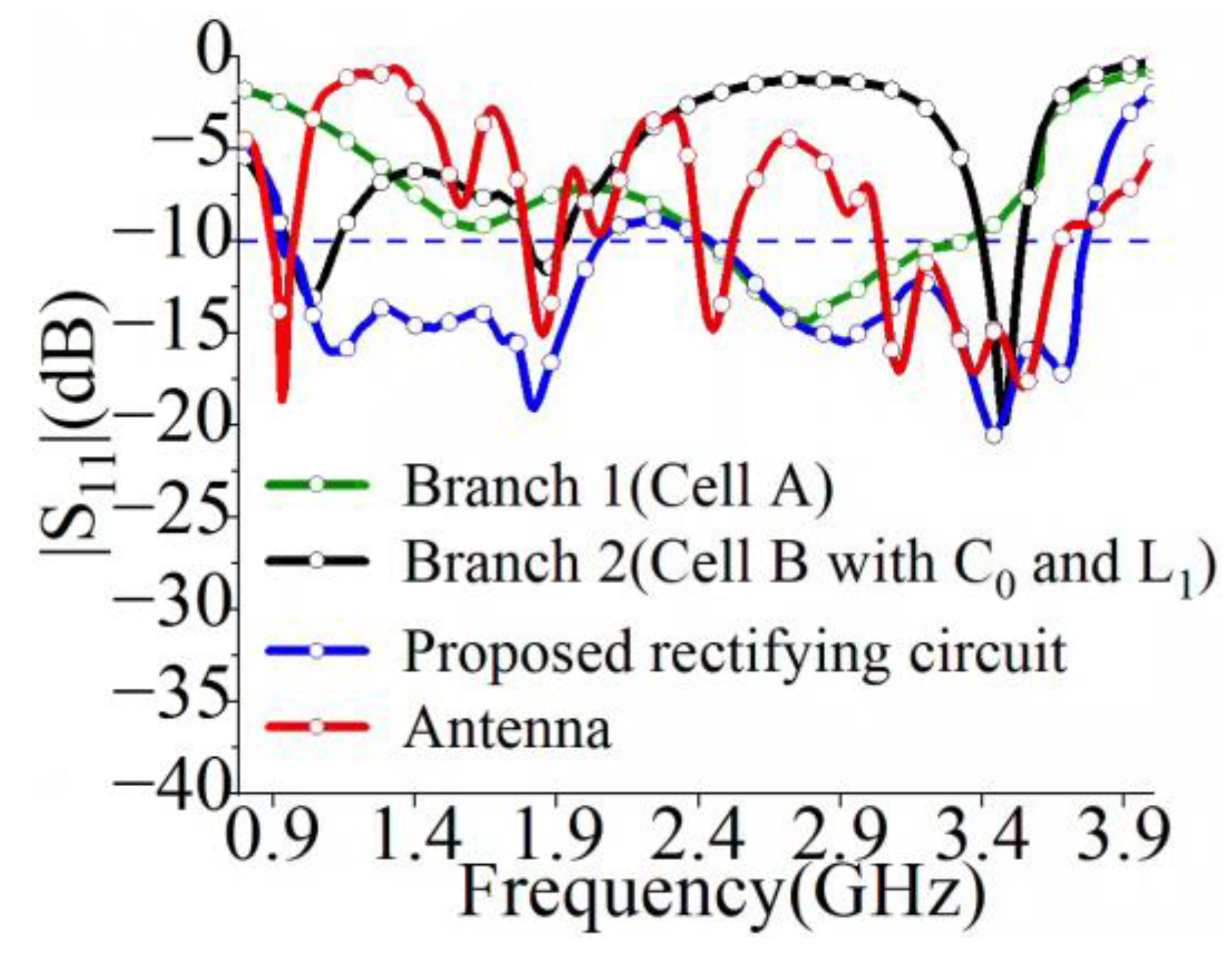
3. Multi-Frequency Rectifier Circuit Design
4. Performance and Discussion
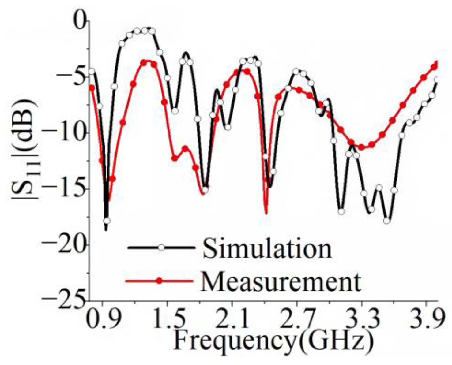
4.1. Performance of Solar Dipole Antenna
4.2. Performance of Rectifier Circuit
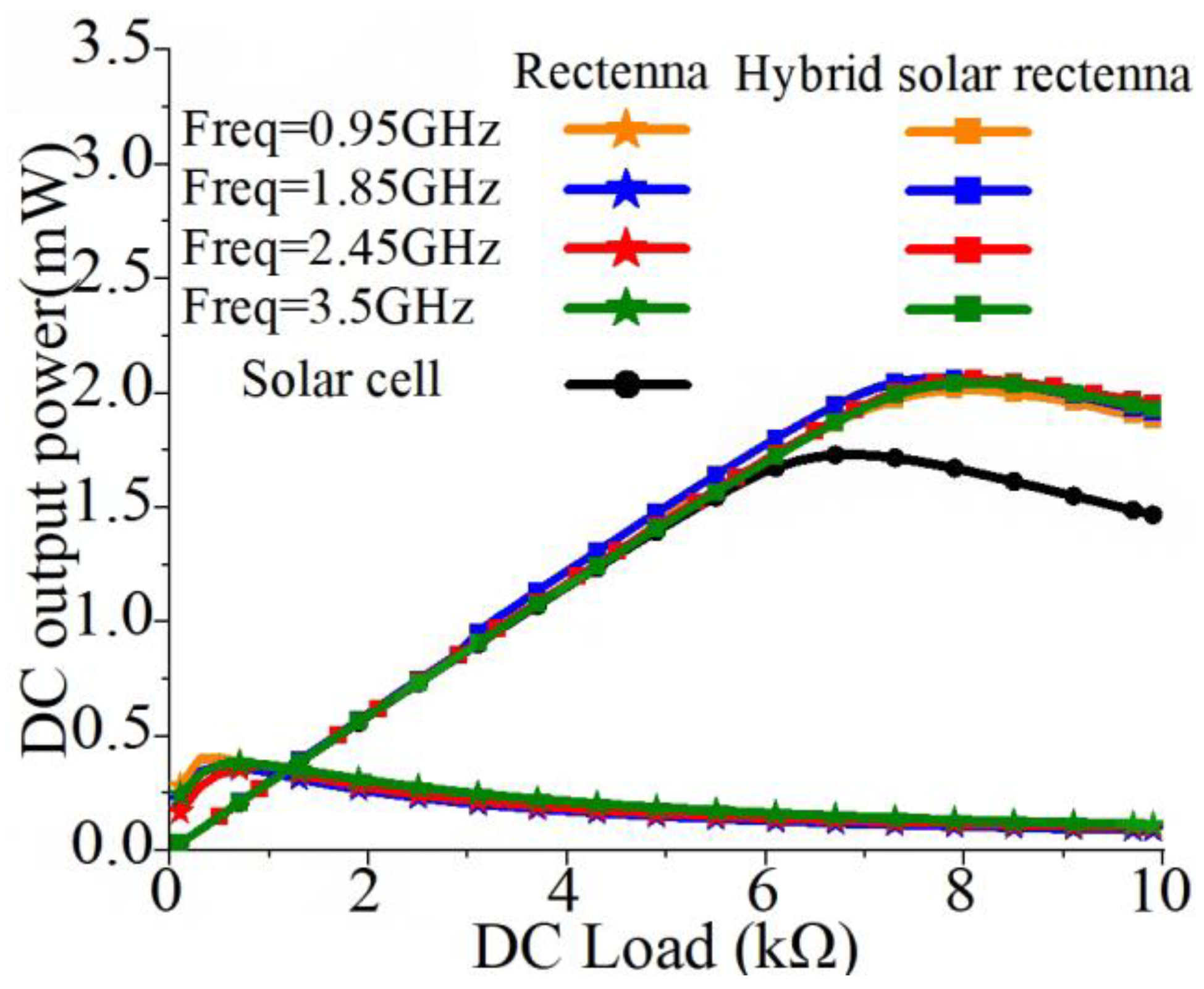
4.3. Performance of Solar Cell Rectenna
- A.
- Under the RF signal radiation.
- B.
- Under the light source.
- C.
- Under microwave and light source.
5. Conclusions
Author Contributions
Funding
Data Availability Statement
Conflicts of Interest
Abbreviations
| OCFD | Off-center-fed Dipole |
| PET | Polyethylene terephthalate |
| DC | Direct Current |
| IoT | Internet of Things |
| RF | Radio Frequency |
| I-V | Current-Voltage |
| Rectenna | Rectifying Antenna |
References
- Wan, S.; Huang, K. Methods for improving the transmission-conversion efficiency from transmitting antenna to rectenna array in microwave power transmission. IEEE Antennas Wirel. Propag. Lett. 2018, 17, 538–542. [Google Scholar] [CrossRef]
- Rodenbeck, C.T.; Tierney, B.B.; Park, J.; Parent, M.G.; DePuma, C.B.; Bauder, C.J.; Pizzillo, T.J.; Jaffe, P.I.; Simakauskas, B.H.; Mayhan, T. Terrestrial microwave power beaming. IEEE J. Microw. 2022, 2, 28–43. [Google Scholar] [CrossRef]
- He, P.; Zhao, D.; Liu, L.; Xu, J.; Zheng, Q.; Yu, C.; You, X. A W-Band 2 × 2 Rectenna Array with On-Chip CMOS Switching Rectifier and On-PCB Tapered Slot Antenna for Wireless Power Transfer. IEEE Trans. Microw. Theory Tech. 2021, 69, 969–979. [Google Scholar] [CrossRef]
- Karampatea, A.; Siakavara, K. Hybrid rectennas of printed dipole type on double negative dielectric media for powering sensors via RF ambient energy harvesting. AEU-Int. J. Electron. Commun. 2019, 108, 242–250. [Google Scholar] [CrossRef]
- Mohammadshah, I.; Adelpour, Z.; Sadeghi, M. Customizable and upgradable design triple-band dual circular polarization rectenna for ambient RF energy harvesting. AEU-Int. J. Electron. Commun. 2023, 166, 154662. [Google Scholar] [CrossRef]
- Citroni, R.; Mangini, F.; Frezza, F. Efficient Integration of Ultra-low Power Techniques and Energy Harvesting in Self-Sufficient Devices: A Comprehensive Overview of Current Progress and Future Directions. Sensors 2024, 24, 4471. [Google Scholar] [CrossRef]
- Hamza, M.; Rehman, M.U.; Riaz, A.; Maqsood, Z.; Khan, W.T. Hybrid Dual Band Radio Frequency and Solar Energy Harvesting System for Making Battery-less Sensing Nodes. In Proceedings of the 2021 IEEE Radio and Wireless Symposium (RWS), San Diego, CA, USA, 17–22 January 2021; pp. 116–118. [Google Scholar]
- Yu, B.Y.; Wang, Z.H.; Ju, L.; Zhang, C.; Liu, Z.G.; Tao, L.; Lu, W.B. Flexible and Wearable Hybrid RF and Solar Energy Harvesting System. IEEE Trans. Antennas Propag. 2022, 70, 2223–2233. [Google Scholar] [CrossRef]
- O’Conchubhair, O.; Yang, K.; McEvoy, P.; Ammann, M.J. Amorphous Silicon Solar Vivaldi Antenna. IEEE Antennas Wirel. Propag. Lett. 2016, 15, 893–896. [Google Scholar] [CrossRef]
- Collado, A.; Georgiadis, A. Conformal Hybrid Solar and Electromagnetic (EM) Energy Harvesting Rectenna. IEEE Trans. Circuits Syst. I Regul. Pap. 2013, 60, 2225–2234. [Google Scholar] [CrossRef]
- Zhang, P.; Zhang, X.; Li, L. An Optically Transparent Metantenna for RF Wireless Energy Harvesting. IEEE Trans. Antennas Propag. 2022, 70, 2550–2560. [Google Scholar] [CrossRef]
- Roy, S.; Tiang, J.-J.; Roslee, M.B.; Ahmed, M.T.; Mahmud, M.A.P. A Quad-Band Stacked Hybrid Ambient RF-Solar Energy Harvester with Higher RF-to-DC Rectification Efficiency. IEEE Access 2021, 9, 39303–39321. [Google Scholar] [CrossRef]
- Alzahrani, S.; Alsulami, R. 38 GHz Wideband and High Gain Stacked Antenna Modelling for 5G Applications. In Proceedings of the 2023 International Conference on Radar, Antenna, Microwave, Electronics, and Telecommunications (ICRAMET), Bandung, Indonesia, 15–16 November 2023; pp. 57–60. [Google Scholar]
- Chu, H.; Guo, Y.-X.; Wang, Z. 60-GHz LTCC wideband vertical offcenter dipole antenna and array. IEEE Trans. Antennas Propag. 2013, 61, 153–161. [Google Scholar] [CrossRef]
- Belrose, J.; Bouliane, P. The off-center-fed dipole revisited: A broadband, multiband antenna. QST 1990, 74, 28–34. [Google Scholar]
- Lin, X.; Weng, Z.; Hong, Y.; Zhang, Y. A Wideband Circularly Polarized Dipole Antenna with Compact Size and Low-Pass Filtering Response. Sensors 2024, 24, 3914. [Google Scholar] [CrossRef]
- Li, J.F.; Chen, Z.N.; Wu, D.L.; Zhang, G.; Wu, Y.J. Dual-beam filtering patch antennas for wireless communication application. IEEE Trans. Antennas Propag. 2018, 66, 3730–3734. [Google Scholar] [CrossRef]
- Chen, C. A High Out-of-Band Suppressed Compact Wideband Filtering Dipole Antenna with a Dual-Mode Compressed Parasitic Folded Dipole. IEEE Trans. Antennas Propag. 2022, 70, 8996–9005. [Google Scholar] [CrossRef]
- Liu, P.; Jiang, W.; Hu, W.; Sun, S.-Y.; Gong, S.-X. Wideband Multimode Filtering Circular Patch Antenna. IEEE Trans. Antennas Propag. 2021, 69, 7249–7259. [Google Scholar] [CrossRef]
- Deng, C.; Zhao, Z.; Yu, W. Characteristic Mode Analysis of Circular Microstrip Patch Antenna and Its Application to Pattern Diversity Design. IEEE Access 2022, 10, 2399–2407. [Google Scholar] [CrossRef]
- Wu, C.; Liu, Y.; Lu, S.; Gruszczynski, S.; Yashchyshyn, Y. Convenient waveguide technique for determining permittivity and permeability of materials. IEEE Trans. Microw. Theory Tech. 2020, 68, 4905–4912. [Google Scholar] [CrossRef]
- Wu, P.; Huang, S.Y.; Zhou, W.; Liu, C. One Octave Bandwidth Rectifier with a Frequency Selective Diode Array. IEEE Microw. Wirel. Compon. Lett. 2018, 28, 1008–1010. [Google Scholar] [CrossRef]
- Song, C.; Huang, Y.; Zhou, J.; Carter, P.; Yuan, S.; Xu, Q.; Fei, Z. Matching Network Elimination in Broadband Rectennas for High-Efficiency Wireless Power Transfer and Energy Harvesting. IEEE Trans. Ind. Electron. 2017, 64, 3950–3961. [Google Scholar] [CrossRef]
- Balanis, C.A. Antenna Theory Analysis and Design, 2nd ed.; John Wiley & Sons: Hoboken, NJ, USA, 1997; p. 86. [Google Scholar]


| Frequency (GHz) | PET Film ԑr | PET tanδ | Solar Cell ԑr | Solar Cell tanδ |
|---|---|---|---|---|
| 0.9 | 2.921849 | 0.0177 | 5.57–6.15 | 0.04–0.069 |
| 1.8 | 2.979557 | 0.00796 | 5.4–6.0 | 0.067–0.08 |
| 2.4 | 2 893159 | 0.0164 | 5.24–5.83 | 0.063–0.073 |
| 3.5 | 2.890049 | 0.0281 | 5.2–5.8 | 0.078–0.089 |
| Frequency (GHz) | 0.95 | 1.85 | 2.45 | 3.5 |
|---|---|---|---|---|
| Antenna R (Ω) | 25.1 − j47.7 | 59.2 − j5.9 | 38.7 − j15 | 35.7 − j7.2 |
| Rectifier circuit R (Ω) | 29.6 − j37.3 | 57.7 + j0.83 | 37.5 + j16.5 | 44.4 + j7.4 |
| Frequency (GHz) | Realized Gain (dBi) | Directivity (dBi) | Efficiency (%) |
|---|---|---|---|
| 0.9 | 2.34 | 3.2 | 82.05 |
| 1.8 | 5.5 | 6.16 | 86 |
| 2.4 | 6.4 | 7.03 | 86.5 |
| 3.5 | 8 | 8.51 | 88.93 |
| Ref. | Freq. (GHz) | Ant. Eff. | Rec. Eff. | Electric Dim. | Gain (dBi) | Tot. Eff. | Hybrid Energy Harvesting |
|---|---|---|---|---|---|---|---|
| [7] | 1.85 2.45 | N/A | 52.1% 42.1% | N/A | 3.84@1.8 GHz 5.45@2.4 GHz | N/A | 0.1929 mW @100m W/cm2 (−10 dBm) |
| [8] | 3.5 5 | 33.4% 57.3% | 54.67% 6% | 0.304 × 0.202 × 0.0012 | 2.24@3.5 GHz 4.03@5 GHz | 18.26% 3.44% | 1000 uW 250 uW @210 lux (14 dBm) |
| [9] | 0.95 1.87 2.45 | 84% 78% 70% | N/A | N/A | 0.04@0.95 GHz 3.91@1.87 GHz 5.28@2.45 GHz | N/A | 3.06 uW 2.28 uW 0.42 uW @17.4 mW/cm2 (−10 dBm) |
| [10] | 0.85 1.85 2.45 | N/A | 15% | 0.0369 × 0.0315 × 0.0001 | −3.27@0.85 GHz 2.18@1.85 GHz 2.23@2.45 GHz | N/A | N/A |
| [11] | 1.7 1.9 2.1 | 21.2% 22.3% 13.5% | 57.5% 65% 61.5% | 0.183 × 0.183 × 0.18 | 1.3@1.9 GHz | 12.2% 14.5% 8.3% | N/A |
| [12] | 0.9 1.45 1.81 2.25 | 65% 65.3% 65% 66.2% | 24.6% 17.3% 46.5% 12.4% | 0.48 × 0.48 × 0.0048 | 4.1@0.9 GHz 4.2@1.45 GHz 5@1.81 GHz 4.8@2.25 GHz | 15.99% 11.3% 30.23% 8.21% | 0.688 V @100 μW/cm2 (−20 dBm) |
| This Work | 0.95 1.85 2.45 3.5 | 82.05 86 86.5 88.93 | 56.94% 54.5% 54.11% 56.56% | 0.39 × 0.27 × 0.081 | 2.34@0.95 GHz 5.5@1.84 GHz 6.34@2.45 GHz 8@3.5 GHz | 48.49% 56.59% 50.08% 51.76% | 2.066 mW 2.0152 mW 2.062 mW 2.0451 mW @1500 lux (0 dBm) |
Disclaimer/Publisher’s Note: The statements, opinions and data contained in all publications are solely those of the individual author(s) and contributor(s) and not of MDPI and/or the editor(s). MDPI and/or the editor(s) disclaim responsibility for any injury to people or property resulting from any ideas, methods, instructions or products referred to in the content. |
© 2025 by the authors. Licensee MDPI, Basel, Switzerland. This article is an open access article distributed under the terms and conditions of the Creative Commons Attribution (CC BY) license (https://creativecommons.org/licenses/by/4.0/).
Share and Cite
Luo, X.; Lu, P.; Wang, C.; Huang, K. Multi-Frequency Solar Rectenna Design for Hybrid Radio Frequency–Solar Energy Harvester. Energies 2025, 18, 2372. https://doi.org/10.3390/en18092372
Luo X, Lu P, Wang C, Huang K. Multi-Frequency Solar Rectenna Design for Hybrid Radio Frequency–Solar Energy Harvester. Energies. 2025; 18(9):2372. https://doi.org/10.3390/en18092372
Chicago/Turabian StyleLuo, Xue, Ping Lu, Ce Wang, and Kama Huang. 2025. "Multi-Frequency Solar Rectenna Design for Hybrid Radio Frequency–Solar Energy Harvester" Energies 18, no. 9: 2372. https://doi.org/10.3390/en18092372
APA StyleLuo, X., Lu, P., Wang, C., & Huang, K. (2025). Multi-Frequency Solar Rectenna Design for Hybrid Radio Frequency–Solar Energy Harvester. Energies, 18(9), 2372. https://doi.org/10.3390/en18092372