1. Introduction
The effective operation of thermal substations is essential for achieving energy efficiency and sustainability objectives in modern district heating systems. Within district heating networks, the reduction in the primary return temperature has emerged as a critical parameter, as it directly influences energy consumption, operational efficiency, and the environmental impact of the system. Lower return temperatures not only decrease distribution losses and improve the efficiency of heat production, but also enable the integration of renewable heat sources, such as industrial waste heat and geothermal energy [
1]. In this context, low primary return temperature represents a key strategy for the decarbonisation of district heating systems. However, the successful implementation of district heating networks hinges on the ability to manage complex interactions between substation design, control logic, and end-user consumption behaviour. In particular, the coordination of DHW production and space heating (SH) demand presents significant challenges, as both subsystems contribute to the primary return temperature. To achieve the full potential of reduced return temperature, it is necessary to optimise the hydraulic and thermal performance of substations through appropriate design configurations, intelligent control strategies, and dynamic modelling approaches that reflect real-world operating conditions.
Braas et al. [
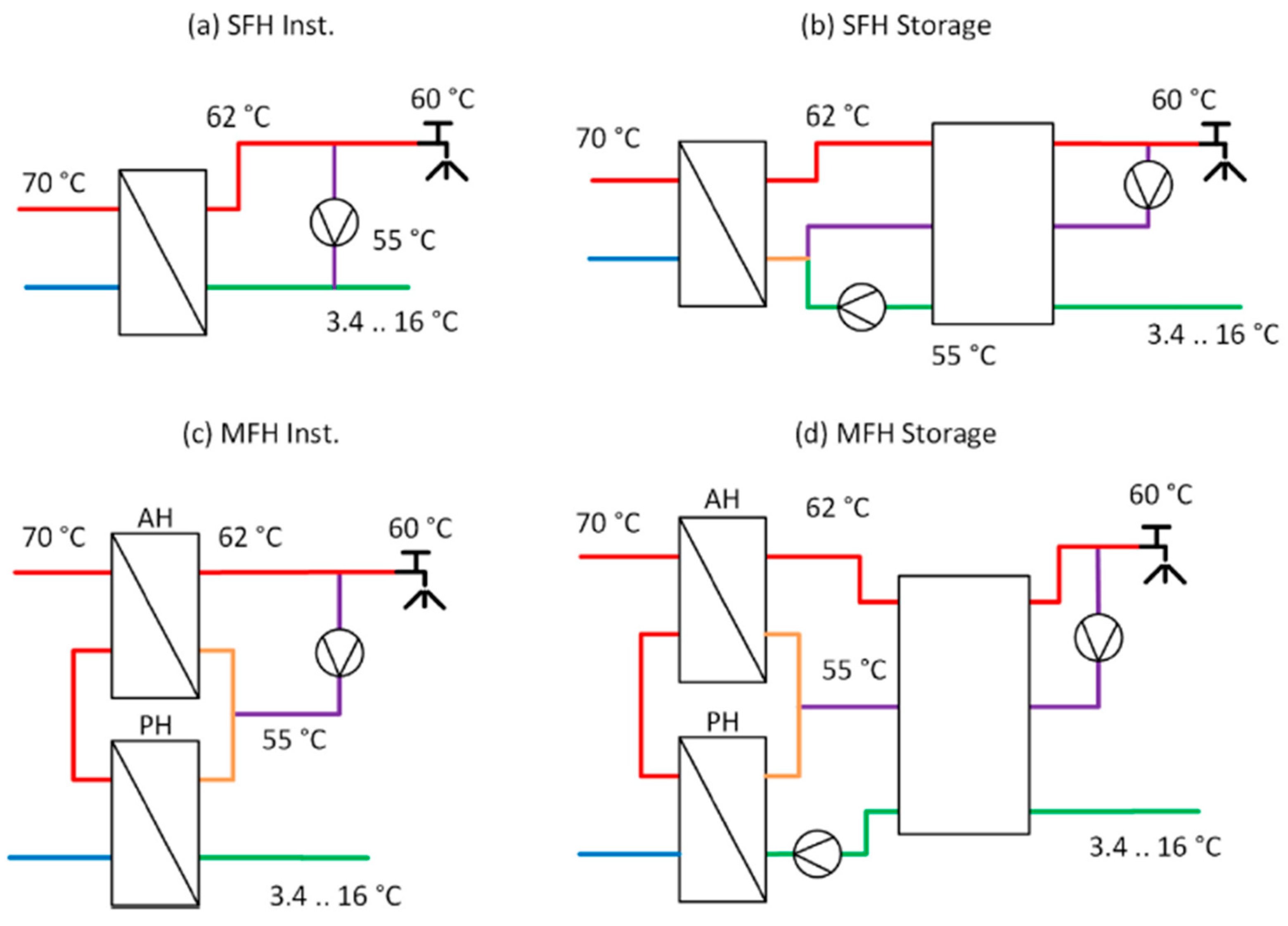
2] explored the impact of DHW preparation on the load profiles of district heating systems, focusing particularly on peak loads arising from simultaneity and the dynamics of primary return temperatures. Utilising TRNSYS simulation software and the DHWcalc tool, their study examined various DHW production systems, as depicted in
Figure 1, including both fresh-water modules and DHW storage tank configurations, across different building types including both single-family houses (SFH) and multi-family houses (MFH). They found that the characteristics of the DHW consumption have a significant effect on the annual heat demand and primary network temperatures, which are critical to ensure the economic viability and sustainability of district heating networks. Additionally, they emphasised the importance of carefully selecting statistical methods and appropriate time intervals for generating load profiles, as these factors greatly influence peak performance requirements, the sizing of DHW storage, and ultimately, the hydraulic design of district heating systems [
2].
Tijs Van Oevelen et al. [
3] investigated optimisation strategies for the primary return temperature in district heating systems, emphasising its key role in enhancing network efficiency and reducing energy losses. Their research aimed to develop control techniques for heating substations to lower this temperature effectively. Similarly, Qinjiang Yang et al. [
4] explored the reduction potential of the primary return temperature, finding that in a Danish multi-apartment building, it could decrease from 46.4 °C to 34.1 °C with a conventional serial connection, and down to 27.9 °C with a parallel setup, where the serial and parallel configurations refer to the specific arrangement of the SH and DHW production heat exchangers (HX) within the substation [
4].
To reduce the primary return temperatures in district heating systems, a variety of technical and operational strategies have been explored. Among these, the implementation of instantaneous DHW preparation has emerged as an effective approach, as it minimises heat losses and maintains low primary return temperatures by eliminating the need for DHW storage. However, this method is typically associated with high peak thermal loads, necessitating the use of larger, and consequently more costly, heat exchangers to accommodate short-duration demand peaks [
4,
5].
To mitigate the challenge of high peak demands, several studies have proposed the integration of thermal storage tanks into the primary network at the substation level. These tanks function as thermal buffers, absorbing fluctuations in demand and enabling a reduction in the required heat exchanger capacity. Consequently, a more stable operation can be achieved, although higher return temperatures are expected [
5,
6,
7,
8].
Primary return temperatures are influenced by both SH and DHW demands. Despite this, the scope of existing literature is sometimes limited in focus; some studies concentrate only on the impact of space heating [
8,
9,
10], while others investigate only the role of DHW consumption [
2,
7]. A bigger body of research addresses the combined effects of SH and DHW preparation, providing a more integrated perspective on the drivers of the primary return temperature behaviour [
4,
5,
6,
7,
8,
9,
10,
11,
12,
13,
14,
15,
16].
Another critical aspect concerns the role of the DHW circulation loop, which is indispensable for ensuring user comfort by delivering immediate access to hot water at all points of use within a building. Nevertheless, continuous DHW circulation contributes to considerable distribution losses, particularly in extensive or inadequately insulated networks. These losses contribute to elevated primary return temperatures and increased energy consumption under certain operating conditions. When the returning DHW circulation flow exhibits higher temperatures, the resulting primary return temperature also rises, thereby reducing the overall efficiency of district heating systems. Only a few recent studies have examined the effect of DHW circulation [
1,
2,
4,
5,
6,
14,
15]. The inclusion of the DHW circulation loop in detailed hydraulic-thermal simulations has proven essential for accurately evaluating its impact on system overall performance and identifying viable pathways for improving energy efficiency and reducing return temperatures.
Table 1 provides a comprehensive overview of the system configurations, summarising their key characteristics, design principles, and functional components.
This study focuses on the detailed simulation-based analysis of DHS configurations commonly deployed in Budapest. Three distinct DHW connection schemes were investigated using dynamic models developed in MATLAB Simulink. The primary objective was to assess how different DHW connection designs and operational parameters influence the reduction in primary return temperatures, particularly emphasizing the effects of varying DHW circulation flow rates and consumption patterns. A constant secondary mass flow rate for the SH systems was maintained to ensure consistency across simulations. The investigation specifically targets DHS configurations including two- and three-heat exchanger layouts. Special emphasis was placed on the three-heat exchanger setup, featuring separate preheating and after-heating stages, as this arrangement was hypothesised to deliver the greatest reductions in primary return temperature. Although both single and dual pump arrangements are used in practice, our analysis primarily concentrated on single pump configurations, reflecting the predominant operational practice in Budapest. All system parameters and operational profiles employed in the simulations were based on empirical data collected from a DHS located at Harmat Street 74, District X, Budapest, Hungary. This ensured a realistic and accurate representation of the physical systems under investigation.
A Grey Box modelling [
22] approach was employed to integrate empirical measurements with partial physical system knowledge, reaching an optimal balance between model accuracy and practical applicability. This methodology supports the development of a robust yet manageable simulation environment, suitable for engineering applications. This research aims to establish a comprehensive dynamic simulation framework that captures the complex interactions between SH and DHW demands within the DHS. Particular attention was given to the dynamic modelling of DHW circulation systems and storage tank behaviour, aspects that are often oversimplified or neglected in traditional modelling approaches. The model relies on measured DHW consumption profiles, ensuring the use of realistic boundary conditions and demand scenarios. The developed simulation environment integrates both hydraulic and thermal domains, enabling the accurate representation of flow distribution, pressure losses, and heat transfer processes within the substation’s key components. This multi-domain approach facilitates a detailed analysis of transient thermal and hydraulic behaviours and the assessment of various control strategies under dynamic operational conditions. The findings of this study are intended to enhance the understanding of SH and DHW system interactions, offering valuable insights for the design, control, and optimization of energy-efficient, low-temperature district heating networks. Furthermore, the developed modelling framework lays the groundwork for future digital twin applications, supporting real-time monitoring, fault detection, and operational optimization in modern district heating systems.
The structure of this paper is organised as follows.
Section 2 describes the system boundaries and introduces the applied modelling methodology. It includes the justification for adopting a Grey Box modelling approach, the description of the three analysed district heating substation configurations (v1, v2, and v3), the structure and assumptions of the MATLAB Simulink-based physical system model, the detailed representation of HX and TST, and the formulation of simulation scenarios, including boundary conditions and solver settings.
Section 3 presents the simulation results, beginning with an analysis of the relationship between DHW consumption and primary return temperature using both weighted and unweighted evaluation methods. This is followed by a comparative performance analysis of the three configurations under varying DHW circulation strategies and DHW consumption conditions, along with an assessment of the operational behaviour of the DHW storage tank and the interaction between DHW circulation flow and return temperature.
Section 4 provides a critical discussion of the results, addressing the effects of load variations, the implications of DHW control strategies, and the practical constraints of the modelling assumptions and configurations examined. Finally,
Section 5 concludes the paper by summarizing the key findings, highlighting the methodological limitations, and outlining future research directions, including the need for empirical validation, seasonal performance evaluation, and the integration of advanced control strategies for real-world applications.
2. Materials and Methods
In this study, the modelling framework was developed in MATLAB Simulink, which enables the dynamic simulation of complex thermohydraulic systems through a modular, block-based structure. The objective was to investigate various DHW and SH substation configurations in a district heating context, with a focus on primary return temperature reduction strategies. The model integrates both thermal and hydraulic domains, enabling the detailed representation of component-level interactions, such as heat exchanger performance, storage tank dynamics, and circulation loop behaviour. Building on previous studies that employed either simplified or static modelling approaches, this work adopts a Grey Box methodology, combining theoretical system knowledge with empirical input data. This approach was chosen due to the lack of complete information on certain boundary conditions and internal system parameters, which rendered purely White Box [
23] models impractical, while allowing for deeper physical interpretation than Black Box [
24] methods.
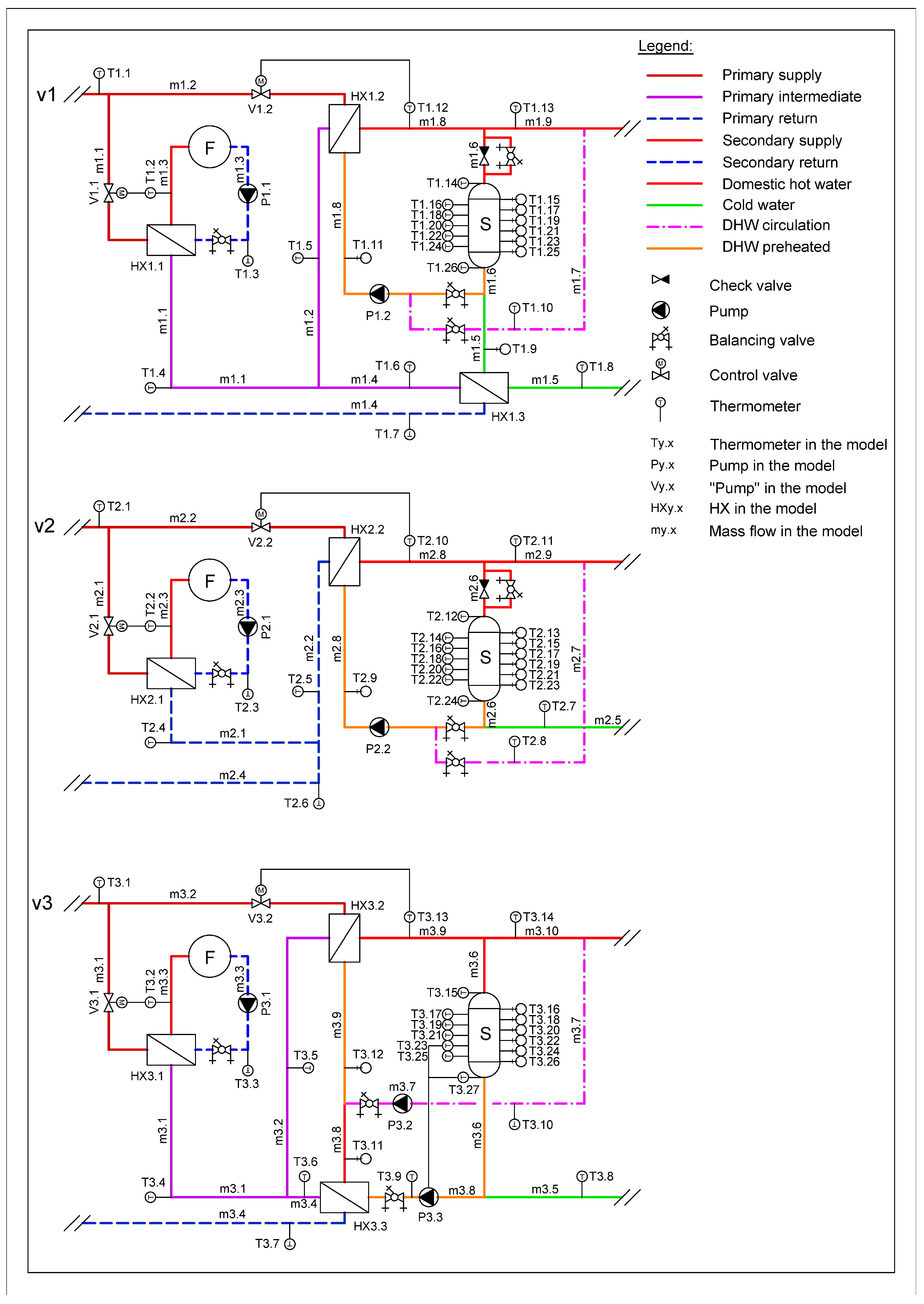
In the literature, various configurations have been examined individually, but comparative analyses within a unified simulation environment remain limited. Therefore, this study aims to bridge this gap by implementing and analysing three widely used substation configurations under harmonised conditions. The detailed structure of each configuration and its modelling in Simulink is presented in the following sections. To assess the impact of different substation configurations, three distinct simulation models, labelled v1, v2, and v3, were developed, as illustrated in
Figure 2. In the applied labelling convention, the first digit of each identifier corresponds to the specific substation configuration (i.e., v1 = 1, v2 = 2, v3 = 3), whereas the second digit designates the numerical order of the associated temperature sensor within the respective system layout.
The v1 configuration includes three heat exchangers, which is currently widely implemented by FŐTÁV in Budapest. This setup consists of a dedicated SH heat exchanger (HX1.1) and two DHW heat exchangers, a preheater (HX1.3) and an after heater (HX1.2). A single circulation pump (P1.2) serves both the DHW storage tank charging and the DHW circulation loop, so the mass flow rate to fill the storage tank and the circulating mass flow rate are determined as a function of the DHW consumption. In this configuration, cold water first enters the preheater (HX1.3), where it is partially heated. The preheated water is then divided between the after heater (HX1.2) and the DHW storage tank. DHW circulation is maintained between the preheater and the after heater to ensure immediate hot water availability. Since the storage tank is discharged from the bottom, where the temperature may vary depending on stratification and prior consumption, the available thermal capacity of the tank is highly dependent on the actual DHW demand. This configuration has been used within FŐTÁV’s DHN in Budapest since approximately 2013 and serves as a reference point for evaluating alternative substation layouts.
The v2 configuration represents a simplified two-heat-exchanger system, comprising one heat exchanger dedicated to SH (HX2.1) and one for DHW production (HX2.2). The primary distinction relative to the v1 configuration lies in the hydraulic separation between the SH and DHW circuits; the primary-side mass flow exiting the SH heat exchanger (HX2.1) does not contribute to DHW preparation, which results in less effective primary return temperature reduction. In this setup, the DHW storage tank is discharged from the bottom using cold water, thereby enabling a precise calculation of the extractable thermal capacity. Like the v1 configuration, a single circulation pump is responsible for both the charging of the storage tank and the DHW circulation loop. As a result, continuous storage replenishment is required to maintain system stability and ensure consistent hot water availability. This configuration was used by FŐTÁV between 2006 and 2013 but is still widely used in district heating systems in Budapest.
The v3 configuration, like v1, is a three-heat-exchanger system; however, it distinguishes itself by employing separate pumps for DHW circulation (P3.2) and storage tank charging (P3.3). This design eliminates the need for continuous (24 h) distributed storage charging, allowing for intermittent operation based on consumption demand. Specifically, storage charging is initiated only when the tank temperature falls below a predefined threshold and is terminated once the target temperature is reached, thereby improving operational efficiency. The DHW circulation loop is operated by its own dedicated pump, which transports water between the preheater and the after heater depending on the prevailing thermal conditions—a configuration commonly referred to as “mid-connected circulation.” Like the previous configurations, the storage tank is discharged using cold water, enabling the precise calculation of the extractable thermal energy. The use of an independently controlled storage charging pump allows for the functional division of the tank into two thermal volumes: an active (net) volume, from which the useful energy is extracted, and a hysteresis volume, which accommodates operational variability. Owing to its enhanced control logic and intermittent charging strategy, the v3 configuration is expected to deliver the most favourable performance in terms of reducing the primary return temperature. The key technical parameters of the components used in the heating substation configurations and modelled temperature ranges are summarised in
Table 2.
Given our objective to perform a detailed and physically meaningful analysis of the mechanical and control subsystems, Grey Box modelling offers a necessary balance between theoretical representation and empirical data fitting, thus enabling more robust system identification and dynamic performance evaluation. MATLAB Simulink provides a suitable platform for the integrated analysis of mechanical and automation processes within thermal-hydraulic systems. The modelling approach employed in this study was based on the interconnection of modular blocks, through which the thermodynamic and fluid dynamic behaviour of the system was formulated, complemented by the mechanical configuration of the substation. Accurate representation of real-world system operation necessitates the inclusion of various control and measurement elements, such as actuators, temperature sensors, and PID controllers. These components are essential for simulating dynamic control responses and maintaining operational stability under varying boundary conditions. During the modelling process, standardised components from the Simulink library were used. These components have been validated by the software developers for their operational reliability, and their underlying mathematical formulations are publicly documented. Owing to the considerable number of unknown or unavailable parameters associated with the DHS configuration, certain modelling simplifications were necessary to ensure the feasibility and stability of the simulation.
One such simplification concerned the management of pressure and pressure losses, which were not dynamically controlled but provided with predefined baselines. This approach was deemed acceptable, given that typical pressure drops across district heating substations are in the order of 1 bar—a magnitude that exerts a negligible influence on thermal performance. In addition, the system under study is not modelled as a closed hydraulic circuit, which further justifies the omission of detailed pressure dynamics from the simulation framework, but it is important to note that this does not have a significant impact on the modelling as the real substation handles this adequately. Flow rate variations resulting from pressure fluctuations within the system were managed by using controlled pumps. As pressure dynamics were not incorporated into the model, actual pump behaviour—dependent on pressure–flow relationships—was replaced by idealised theoretical pumps, as in the work of Vandermeulen et al. [
19]. These theoretical pumps were assumed to maintain a constant volumetric flow rate, independent of the prevailing pressure conditions in the system, according to the findings of Song et al. [
25].
For similar reasons, the pressure-drop-based controllers typically associated with heat exchangers were also substituted with idealised flow-controlled pumps. This modelling simplification allowed for the regulation of flow rates without the need to simulate the complex pressure interactions inherent in real hydraulic systems, thereby focusing the analysis on thermal behaviour and system topology. Given the lack of detailed hydraulic data for both the primary and secondary heating circuits, the decision to omit the real pump models from the simulation was justified. On the SH side, a constant mass flow was considered and only the supply temperature was controlled. The hydraulics of the DHW pumps are extremely complex, which was approximated in a linear way in our work, which satisfactorily approximated reality. However, if the hydraulic parameters of the system were available, real pumps could be implemented within the model by defining their characteristic performance curves, thereby enabling a more realistic representation of pressure–flow interactions and pump energy consumption.
In the simulation model, theoretical pumps were employed to transport fluids to and from idealised infinite reservoirs, which represented the thermal boundary conditions of the district heating provider’s central plant. These reservoirs were thermally controlled in accordance with the input data, ensuring that the temperatures of the working fluids—including the primary supply, secondary return, cold water inlet, and DHW circulation return—remained consistent with realistic operating conditions. The theoretical pumps extracted fluid from these reservoirs and delivered it to the system without imposing additional pressure or thermal constraints, thereby enabling the isolated analysis of hydraulic and thermal interactions within the modelled substation configurations [
26].
In our study, a more detailed and physically representative heat exchanger model was employed compared to the simplified approaches commonly adopted in the existing literature. Typical models found in the literature often rely on approximations based on the logarithmic mean temperature difference method [
1,
3,
19] or simplified energy balance equations [
5,
6,
25], which neglect detailed flow and heat transfer dynamics. In contrast, our approach incorporates the heat exchangers’ geometric, fluid dynamic, and thermal modelling, allowing for a more accurate representation of real operating conditions and internal processes. As a result of this enhanced modelling complexity, direct comparisons between our results and previously reported design parameters are inherently constrained. Specifically, the level of detail incorporated in our model captures thermodynamic and operational phenomena often neglected or approximated in traditional models, thereby limiting the validity of straightforward parameter-by-parameter benchmarking against earlier studies.
In the modelling of the heat exchangers, their geometric and thermal characteristics were defined based on detailed technical data obtained from manufacturer datasheets and product catalogues. This approach allowed for the development of a significantly more accurate representation than conventional models relying solely on logarithmic mean temperature difference calculations. The model incorporated many parameters, including fin depth, spacing, inclination angle, material properties, thermal resistance, fouling factor, overall dimensions, number of plates, and pipe connection sizes. These detailed inputs enabled the simulation to reflect the actual performance characteristics of the heat exchangers more closely. For this purpose, the dedicated plate heat exchanger block available in Simulink was utilised, as it supports the integration of such detailed physical specifications and enables dynamic thermal-hydraulic analysis under varying operating conditions [
27]. The heat transfer coefficient model employed in this study is based on the Colburn equation, which estimates the convective heat transfer coefficient using empirically derived Colburn correlation coefficients. This approach relates dimensionless parameters to capture the effects of flow conditions and geometry on heat transfer performance. The Nusselt number (Nu), representing the dimensionless heat transfer coefficient, is calculated as follows [
27]:
The indices and multiplicative coefficients applied in the model were selected based on the methodologies presented in [
28,
29], with specific consideration given to a fin inclination angle of 65°. The selected parameter values are summarised in
Table 3:
The mass flow rates entering and exiting the heat exchangers often require appropriate merging or splitting to accommodate the operational demands of the system. To achieve this, a T-junction fitting was implemented, enabling dynamic mass flow distribution. This component ensures hydraulically consistent flow division and combination at the junctions, thereby maintaining accurate mass and energy balances within the thermal system under varying operating scenarios [
30].
A one-dimensional thermal storage model was adopted for the representation of the DHW storage tank, in line with methodologies identified in the literature review. For this purpose, the fixed-volume storage tank model available in MATLAB Simulink was selected, as it offers sufficient flexibility for the intended application. Specifically, the model supports up to four configurable inlet/outlet ports and an additional interface for coupling with an external thermal source or heat dissipation pathway. This modelling approach enables the representation of stratified temperature layers and dynamic charging/discharging behaviour under varying operating conditions [
31]. The thermal storage unit was modelled as a “thermally insulated storage tank” in the simulation environment due to certain simplifications and the lack of detailed thermal loss data. This modelling approach assumes that no heat exchange occurs between the storage unit and its surroundings, which is acceptable considering that adequate insulation is typically applied in practice. M. Reda Haddouche et al. [
32] explored the dynamics of stratified hot water storage tanks, focusing on temperature stratification during both charging and discharging cycles. Based on mass and energy conservation principles, they developed a one-dimensional numerical model designed to simulate temperature distributions within the tank. To validate the model, they conducted experimental measurements, which led to enhancements in the model by increasing the number of computational nodes. This iterative process progressively improved the alignment between the numerical results and the experimental data, as illustrated in
Figure 3.
To improve the representational accuracy of the thermal stratification within the storage reservoir, the tank was discretised into multiple smaller volumes connected in series. This approach follows established modelling methodologies in the literature [
32,
33,
34,
35], allowing for a more detailed depiction of vertical temperature gradients. Specifically, the storage unit was subdivided into 100 layers, each representing a thermally homogeneous sub-volume, thereby enabling a refined approximation of the dynamic thermal behaviour of the stratified storage system. To perform the simulations, it is essential to select an appropriate numerical solver, as it governs the underlying solution algorithm and time integration strategy.
The simulation environment allows for the use of either fixed-step or variable-step solvers. Based on practical experience with modelling highly dynamic thermal-hydraulic systems, the application of fixed time steps was found to frequently result in numerical inaccuracies or notable deviations from the expected system behaviour. In contrast, simulations performed using a variable time-stepping approach produced results that more closely aligned with theoretical expectations and analytical estimates. Consequently, the variable-step solver was selected for this study, as it provided superior accuracy and numerical stability under the investigated transient operating conditions. When employing variable time stepping, the simulation software adaptively reduces the integration time interval during periods of rapid parameter variation, thereby increasing the temporal resolution and enhancing the accuracy of the results. In the present study, the maximum allowable time step was set to 60 s, corresponding to the temporal resolution of the available input data.
However, due to the stochastic nature of DHW consumption, the solver frequently reduced the time step, resulting in an average integration interval of approximately 5 s throughout the simulations. To accommodate the system’s dynamic behaviour while maintaining computational efficiency, the ODE23 solver was selected. This solver is based on an explicit Runge–Kutta method, offering a suitable balance between accuracy and computational cost for the given application. The simulation was carried out over a continuous two-day period, with data recorded at a temporal resolution of one minute. This resulted in a total of 2880 data points per parameter, enabling a detailed temporal analysis of the system’s dynamic behaviour under varying operating conditions. During the simulations, two distinct levels of DHW consumption and DHW circulation mass flow rates, along with their combinations, were investigated to assess their impact on system performance. In the baseline scenario, a dataset comprising measured DHW consumption and circulation volumetric flow rates was employed, both recorded at one-minute intervals over a two-day period. The circulation flow dataset was derived from a simplified hydraulic calculation applied to the circulation network of the building under investigation. This methodology is consistent with that used in a previous simulation study in 2023, thereby ensuring coherence in modelling assumptions and boundary conditions [
36].
According to the design guidelines of FŐTÁV, the calculated DHW consumption profile for a building corresponds to approximately twice the measured peak consumption. To account for this discrepancy and to evaluate system performance under design-level conditions, additional simulations were conducted by scaling the measured DHW consumption values. In the baseline scenario, the peak DHW consumption reached 36 L/min (referred to as 1 × DHW), whereas, in the amplified scenario, the consumption was increased to 72 L/min (2 × DHW), thereby approximating the design flow conditions specified in the sizing methodology. To assess the impact of increased DHW circulation, a scenario with unregulated circulation was examined, resulting in a significantly elevated recirculated mass flow rate. In the regulated configuration, the circulation volumetric flow rate was set at 7.14 L/min (denoted as 1_Circ.), which was estimated based on the assumed pipe length of the building, the thermal insulation properties of the piping system, and the expected temperature drop, whereas in the unregulated case, a flow rate of 22 L/min was assumed (denoted as 2_Circ.), three times the calculated balanced flowrate. Considering the various combinations of DHW consumption levels, circulation flow rates, and system configurations, a total of 12 distinct simulation cases were defined and analysed. These are summarised in
Table 4, which provides an overview of the investigated scenarios and their corresponding boundary conditions. The MATLAB Simulink model of the district heating substation we investigated is shown in
Figure 4.
3. Results
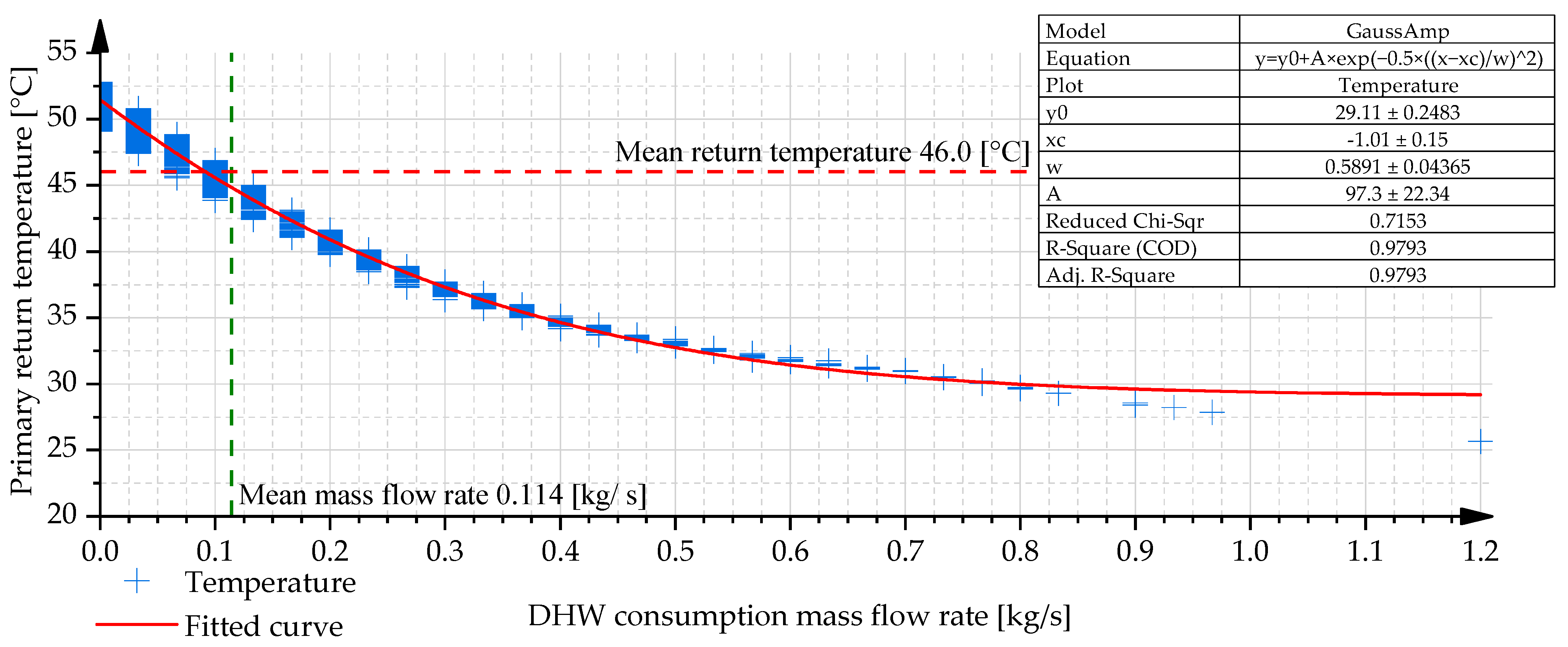
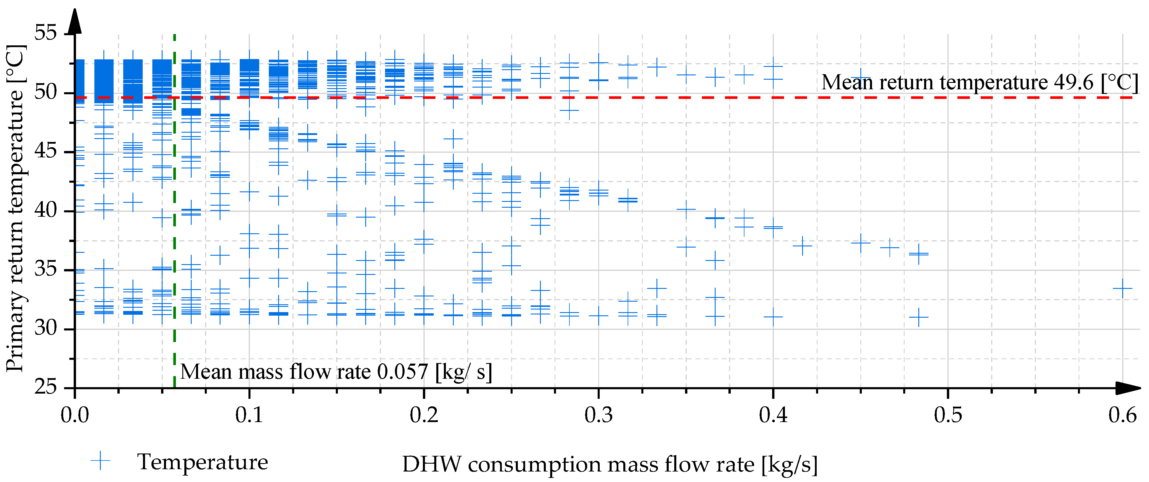
Figure 5 illustrates the variation in the primary return temperature as a function of DHW consumption for configuration v1 under Case I conditions, which assume individual DHW usage combined with controlled circulation. In this configuration, a clear correlation is observed between the DHW consumption and the resulting primary return temperature. The relationship is well approximated by a Gaussian–Amp fitting function, yielding a coefficient of determination (R
2) of 0.9468, indicating a high degree of correlation between the fitted curve and the simulation data. The fitted equation is as follows:
where
mass flow rate of consumption;
constant of DHW consumption;
calculation constant;
calculation constant;
primary return temperature constant;
expected primary return temperature.
The average DHW consumption during the analysed two-day period was 0.057 kg/s, corresponding to approximately 3.42 L/min. The mean primary return temperature associated with this period was 48.3 °C. As illustrated in
Figure 5, the simulation data points exhibit a highly consistent alignment and reveal a strictly monotonically decreasing relationship between DHW mass flow rate and primary return temperature. This trend progressively levels off at higher consumption flow rates, which can be attributed to the fundamental limitations of thermal exchange processes; specifically, the primary return temperature cannot fall below the temperature of the cold water entering the secondary side of the heat exchanger.
Figure A1 shows the v1 configuration in Case II.
Figure 5.
Primary return temperature as a function of DHW consumption for the v1 configuration in case I.
Figure 5.
Primary return temperature as a function of DHW consumption for the v1 configuration in case I.
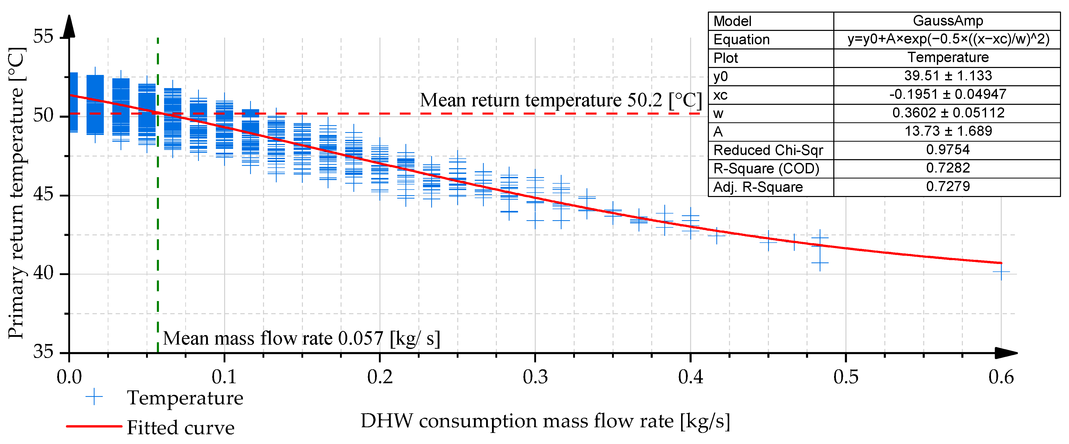
Figure 6 presents the primary return temperature as a function of DHW consumption for configuration v2 under Case II conditions, which assume doubled DHW demand,
Figure A2 shows Case I for a single DHW demand condition. Unlike configuration v1, which employs both preheating and after heating stages for DHW preparation, configuration v2 includes only a single DHW heat exchanger and, as such, does not exhibit a strictly monotonically decreasing return temperature trend. Instead, a distinct minimum is observed at approximately 42 L/min, which corresponds closely to the nominal design flow rate of the DHW subsystem (42.1 L/min). This non-monotonic behaviour is a result of the interplay between the primary-side flow rate and the thermal performance of the DHW heat exchanger. When the primary mass flow rate is insufficient to fully transfer the required heat for DHW preparation, i.e., when the outlet temperature of the DHW heat exchanger is lower than that of the upstream SH heat exchanger—the return temperature decreases monotonically. However, above the design mass flow rate of the heat exchanger (~0.7 kg/s or 42.1 L/min), the primary outlet temperature of the DHW heat exchanger starts to increase, since the heat exchanger can only satisfy the desired DHW temperature with an excess primary mass flow rate, and this excess mass flow rate ultimately results in a higher primary return temperature.
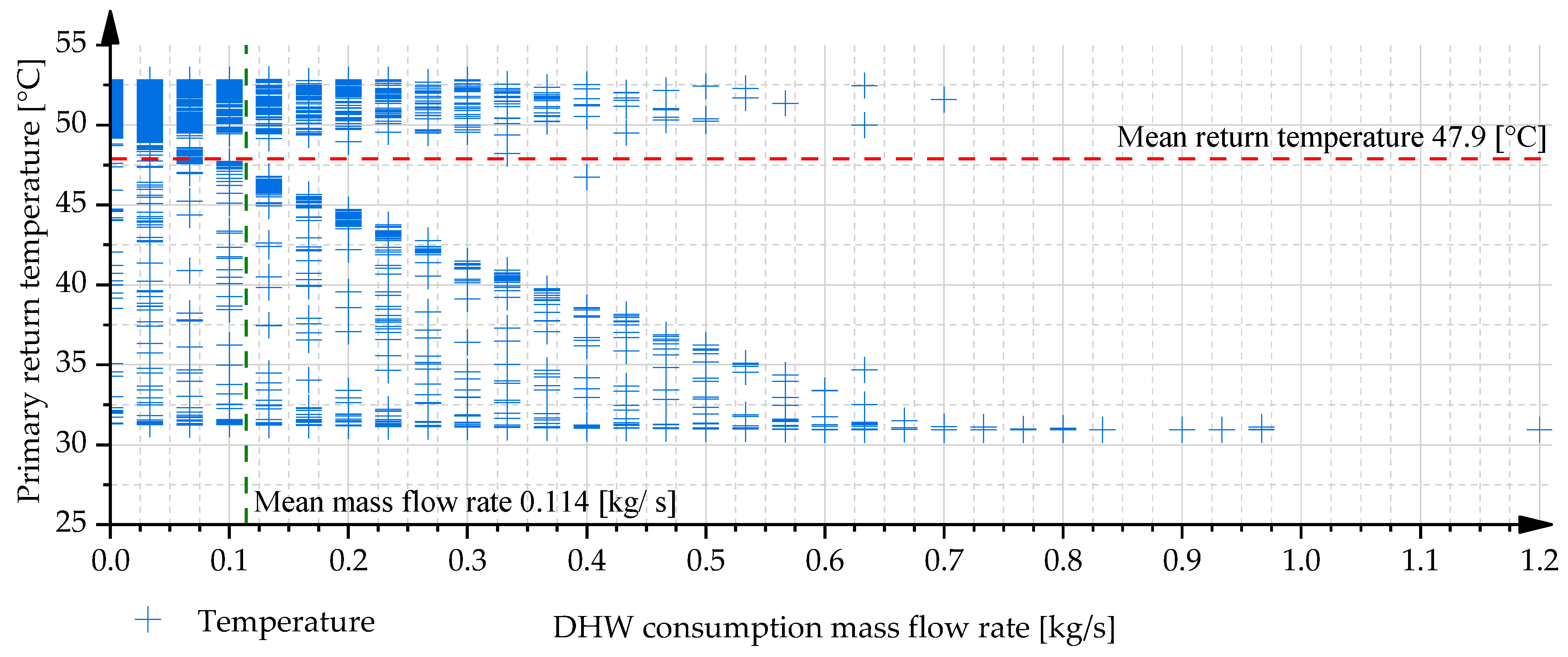
Figure 7 illustrates the behaviour of configuration v3 under Case I conditions, seen in
Figure A3. Primary return temperature as a function of DHW consumption for the v3 configuration in Case II reveals a significantly different thermal response compared to the previously discussed configurations. In this setup, two distinct data clusters are observed, reflecting the influence of a dedicated DHW storage charging pump that operates independently from the DHW circulation loop. When the storage tank is discharging (i.e., the charging pump is inactive), the primary return temperatures tend to stabilise around 52 °C, largely independent of the actual DHW consumption rate. This return temperature results from the combined effect of primary water exiting the SH exchanger and the outlet of the DHW after heater. The system’s operational logic and hydraulic separation of functions lead to a complex return temperature profile that deviates from the patterns seen in configurations v1 and v2. During the charging phase of the DHW storage reservoir, a characteristic right-angled triangular pattern emerges in the data representation. The slope of the hypotenuse in this pattern is determined by the ratio between the storage charging flow rate and the DHW consumption rate. Maximum primary return temperature reduction is achieved when these two values are equal, as this condition results in the preheater’s secondary inlet being supplied with cold water, thereby maximising the temperature differential across the HX. In cases where this balance is not maintained, a mixed temperature—resulting from partial recirculation and storage discharge—enters the preheater, leading to a vertical clustering of results. The vertical positioning of these points along the
Y-axis (representing primary return temperature) is governed by several dynamic operating parameters, including the current storage charge level, the magnitude and direction of changes in DHW consumption, and the mixing flow rates and temperatures in the secondary circuit. These factors collectively influence the thermal state of the system and contribute to the variability observed in the simulation results.
Table 5 presents a summary of the primary return temperature variations across different hydraulic configurations and operational cases. The results indicate that circulation control has a pronounced impact on the primary return temperature for configurations v1 and v2 within the tested parameter ranges. In contrast, for configuration v3, the influence of circulation adjustment is less significant, with observed differences limited to approximately 1–1.5 °C. An increase in DHW consumption—specifically, a doubling of the baseline demand—resulted in a reduction of 1–3 °C in the average primary return temperature. Moreover, when analysing the minimum return temperature values, differences of up to 10 °C were observed between the various configurations and operational conditions, highlighting the sensitivity of the system to both design- and demand-related parameters. The constants used for the fits are listed in
Table 6 and are based on Equation (2).
The primary return temperatures weighted by the DHN mass flow are illustrated in
Figure 8. This weighted approach provides a more accurate representation of the system’s thermal performance by accounting for the varying mass flow rates over time. The equation applied for this evaluation is as follows:
It was observed that, across all examined scenarios, configuration v1 consistently resulted in the lowest primary return temperatures, whereas configuration v2 produced the highest values. In Case I, the system operated with measured DHW volume flow and regulated circulation, while Case III represented the same consumption conditions under uncontrolled circulation. Case II considered a doubled DHW volume flow with regulated circulation, and Case IV examined this increased demand under uncontrolled circulation conditions. The influence of circulation mass flow on the primary return temperature was found to be marginal under the tested conditions. Specifically, Case I and Case III yielded comparable results, as did Case II and Case IV, with temperature differences ranging between 0.1 °C and 0.5 °C. Interestingly, in Cases III and IV, the uncontrolled circulation led to slightly lower primary return temperatures compared to the controlled cases. This can be attributed to the return flow entering the substation at approximately 45 °C, which, instead of being reheated, contributes to a reduction in the overall return temperature.
4. Discussion
This study investigates three DHS configurations (v1, v2, and v3), focusing on their thermal performance with respect to primary return temperature reduction and the efficiency of DHW production and storage. Simulations were conducted in MATLAB Simulink, which provided a suitable environment for modelling the dynamic interactions between hydraulic and thermal components; however, further validation is required to ensure the robustness of the findings. Among the configurations, v2 demonstrated the least favourable performance, with return temperatures reaching approximately 40 °C, while v1 and v3 achieved significantly lower values (around 32 °C), indicating enhanced thermal efficiency. Notably, only configuration v3 utilised the storage tank effectively under standard conditions, whereas v1 and v2 relied on storage charging primarily during elevated DHW demand. The impact of DHW circulation control was minor for v1 and v2, but in the case of v3, controlled circulation yielded a return temperature reduction of up to 1–1.5 °C. When weighted by the primary mass flow, the difference between controlled and uncontrolled circulation scenarios remained minimal (approximately 0.1 °C). Furthermore, increasing DHW consumption led to improved return cooling in v1, with a temperature reduction of up to 6 °C, while in v2, peak loads caused return temperatures to rise by a similar margin. Excessive preheater outlet temperatures in v1 and v3 may introduce operational risks, including limescale formation and potential scalding. To alleviate such problems and to ensure the efficient operation of the substation, it is recommended to use preheater and after heater together, to control the temperature of the preheater precisely and to use a separate DHW circulating and storage charging pump. Despite the simplifications inherent in the model, the findings offer important insights into the influence of configuration design, load variation, and control strategies on substation performance.
Over the course of a year or a heating season, traditional control systems typically exhibit return temperatures between 40 and 55 °C, as reported in the literature, with one study also providing measurement-based validation of these findings, particularly in the presence of DHW circulation or suboptimal control strategies [
16,
20]. For instance, in one study, the annual weighted return temperature for both a continuous flow system and a storage-based district heating system was approximately 50 °C [
16]. Another investigation reported an average return temperature of 44.6 °C in a conventional high-temperature system, which was reduced to 38.6 °C following control optimization [
3]. The impact of control optimization and alternative substation architectures has been extensively studied, with many articles reporting an average return temperature reduction of 3–10 °C compared to conventional reference systems [
3,
15]. For example, the implementation of an optimised substation control reduced the average return temperature by 6 °C, while full system oversizing, e.g., of heat exchangers and radiators, enabled more significant temperature reductions, with decreases of up to 9–10 °C [
3].
Further research should aim to evaluate long-term behaviour, seasonal dynamics, and real-world applicability to support the development of more efficient low-temperature district heating systems. Three heat exchanger configurations were analyzed, similarly to the work of Chardon et al. [
15] and Thorsen et al. [
1], each representing typical substation designs currently in use in Budapest. Among these, configuration v1 corresponds to the standard solution presently implemented by FŐTÁV, the main district heating utility provider. In the context of this study, v1 denotes a substation design comprising three-heat exchangers (SH, DHW preheater, and DHW after heater) and a single DHW circulation pump. Configuration v2 consists of a simplified setup with two-heat exchangers and a single pump responsible for both DHW circulation and storage charging. Configuration v3, on the other hand, includes three heat exchangers along with two separate pumps—one for DHW circulation and one for DHW storage charging—allowing for independent control of these subsystems. This comparative analysis provides valuable insights into the thermal and hydraulic performance of three DHS configurations (v1, v2, and v3), informing the optimization of future low-temperature system designs. The simulation results indicate that the simplest setup, v2, featuring only a single DHW heat exchanger, exhibited the highest primary return temperature, approximately 40 °C under favourable conditions. In contrast, configurations v1 and v3 achieved lower return temperatures, around 32 °C, when simulations were conducted using measured DHW consumption data, which represent only 50% of the design value. When the DHW consumption was doubled to reflect design-level conditions, configuration v1 outperformed the others, reducing the return temperature to as low as 26 °C during peak demand. The utilization of the 300 litre DHW storage tank also varied; v1 and v2 only activated the tank under increased demand, leaving it unused under baseline conditions, while v3 charged the tank intermittently even at lower loads, owing to its hydraulically separated charging circuit with a dedicated pump. This enhanced operational flexibility and system responsiveness. To ensure safe and efficient operation, the recommended configuration for DHW production should include both a preheater and an after heater. The preheater shall be equipped with an overtemperature protection mechanism to prevent scale formation and scalding, and for DHW circulation, hydraulic separation of the storage tank filling circuit from the DHW circulation loop is strongly recommended for proper operation in the building. These findings highlight the importance of integrated design and control strategies for achieving optimal performance in dynamic district heating environments.
Limitations
Although the developed simulation framework provided valuable insights into various DHS configurations’ thermal and hydraulic performance, several limitations must be acknowledged. Further investigations are required to determine the optimal hydraulic integration of the DHW circulation system. While simulation results suggest that supplying the lower connection of the storage tank directly from the cold water inlet could improve the efficiency of the charging process and enable more accurate quantification of the discharged volume, none of the examined coupling strategies—configurations v1, v2, and v3—fully met the identified performance criteria. These findings highlight certain limitations in current design approaches; however, optimizing or strategically combining key elements from different configurations may offer a promising pathway towards more efficient and robust substation designs. Another major limitation is the lack of empirical validation due to the absence of corresponding measured operational data. While the software developer validated the component-level models employed, the validation of the complete, integrated system remains crucial to ensure the reliability of the results. Although the outcomes demonstrate internal consistency and align with theoretical expectations and energy balance principles, empirical confirmation is necessary for broader applicability.
Several modelling simplifications also affect the accuracy of the simulation results. Although the weather data were based on real measurements, the primary supply temperature was derived from a predefined outdoor-temperature-dependent control curve rather than from direct measurement. Furthermore, the secondary SH demand was modelled solely as a function of outdoor temperature, neglecting internal heat gains, occupancy patterns, and building-specific characteristics. These assumptions constrain the model’s ability to accurately reflect real-world dynamic thermal behaviour, particularly under variable or partially loaded conditions. From a hydraulic perspective, pressure losses were assumed as fixed values rather than dynamically calculated, limiting the model’s capability to capture hydraulic interactions and control sensitivities. In the case of DHW demand modelling, consumption profiles were based on measured data; however, they represented only short-term, partial load conditions, without accounting for seasonal variability. DHW circulation mass flow rates were estimated using simplified hydraulic calculations instead of direct measurements, introducing further uncertainty concerning circulation energy demand and thermal losses. Finally, while the configurations studied reflect typical Hungarian system layouts, this may somewhat limit the generalisability of the findings. Nevertheless, the literature indicates that similar DHS designs are employed in other countries, enhancing the broader relevance of the results.
5. Conclusions
The evaluation of the simulation results revealed that none of the examined configurations fully utilised the available 300 L of DHW storage capacity; in all cases, only approximately two-thirds of the total volume was effectively discharged. In configuration v3, the storage charging process was initiated prematurely, relative to the remaining usable volume of the tank, indicating a suboptimal control strategy that could be improved through better timing and logic of storage management. Contrary to initial expectations, the change in the primary return temperature under baseline conditions was negligible—amounting to only 0.1 °C when evaluated as a mass flow weighted average. However, when the DHW consumption was doubled to reflect design-level conditions, the thermal performance changed markedly. In configuration v1, average primary return temperatures decreased by 1 °C to 3 °C, and a reduction of up to 6 °C was observed during peak demand. In contrast, configuration v3 showed little sensitivity to increased consumption due to its operational logic, while configuration v2 exhibited a counterproductive response; peak DHW loads led to a 6 °C increase in return temperature. Across all configurations, differences in return temperatures reached up to 10 °C in unweighted analyses and up to 2 °C when weighted by primary-side mass flow. Additionally, the simulations highlighted a potential risk of overheating in configurations v1 and v3 due to the absence of effective control on the DHW preheater. Outlet temperatures exceeding 50 °C were observed under certain conditions, posing risks of limescale formation in the secondary circuit and scalding at points of use. Although these scenarios have not yet been experimentally validated, they warrant further investigation to ensure safe and efficient system operation.
Although the simulation framework provided valuable insights into the thermal and hydraulic performance of various substation configurations, several limitations must be acknowledged. While the weather data used in the simulations were based on real measured values, the primary supply temperature was not directly measured but derived from a predefined outdoor-temperature-dependent control curve, as applied in DHN. Similarly, the secondary SH demand was modelled solely as a function of outdoor temperature, without accounting for internal heat gains, occupancy patterns, or building-specific characteristics. These simplifications reduce the model’s ability to reflect real-world thermal behaviour, particularly under dynamic or partially loaded conditions. Additionally, pressure losses were not actively calculated; instead, a fixed pressure drop was assumed, which limits the model’s capacity to simulate hydraulic interactions and control sensitivities. Another significant limitation pertains to the modelling of DHW generation and circulation. While the DHW consumption profiles were based on measured data, these represented only short-term and partial design load conditions, without capturing seasonal variability or stochastic user behaviour. Furthermore, the DHW circulation mass flow rates were not based on direct measurements but were instead assumed based on simplified hydraulic calculations, introducing potential uncertainty regarding the actual circulation energy demand and thermal losses. Although MATLAB Simulink offers validated component models, the integrated substation systems have not been empirically verified due to the lack of measured operational data. Finally, the configurations studied reflect typical Hungarian system layouts, which may limit the generalisability of the results, but the literature review shows that the design of the substation we examined is also used in many other countries. Future work should aim to incorporate empirical validation, refined DHW and circulation modelling, seasonal and long-term simulation scenarios, and advanced control strategies to support the practical application of the findings in diverse real-world settings.


