Abstract
We propose a coordinated control strategy for off-grid 10 kV wind–solar–hydrogen energy storage DC microgrid systems based on hybrid energy storage and controllable loads to improve their stability and accommodation level. First, mathematical models of each unit are established based on the operating characteristics of wind turbines, photovoltaic (PV) units, alkaline electrolyzers, fuel cells, and lithium batteries. Second, on the side of the electro-hydrogen hybrid energy storage DC/DC converter, the traditional dual-loop control is improved by proposing a control scheme combining an extended state observer with adaptive backstepping control (ESO-adaptive backstepping). On the load demand side, an electric spring incorporating adaptive fuzzy control (AFC) is introduced to adjust and compensate for the voltage. Finally, an actual case analysis is conducted using data from the Ningbo Cixi hydrogen–electric coupling DC microgrid demonstration project. The results demonstrate that the control method proposed in this study significantly outperforms the traditional double closed-loop control method. Specifically, the proposed method reduces the bus voltage fluctuation range in the presence of load disturbances by 24.07% and decreases the stabilization time by 56.92%. Additionally, the efficiency of the hydrogen fuel cell is enhanced by 31.88%. This control method can be applied to 10 kV DC microgrid systems with distributed energy resources. It aims to reduce the fluctuation amplitude of the DC bus voltage and enhance the system’s ability to withstand transient impact events.
1. Introduction
New power systems are an essential component of new energy systems, with new energy sources becoming the main form of power supply. The key lies in the coordinated development of energy storage with different functional orientations, the introduction of large-scale and cross-regional emerging peak-shaving methods, the achievement of a power and energy balance across different time scales, and the organic integration with other deeply decarbonized energy sources to ultimately realize carbon neutrality.
In the process of building a new power system with new energy as the main body, the high proportion of renewable energy such as wind and solar energy leads to significant power fluctuations and voltage stability challenges in the power grid. As a clean energy carrier with cross-seasonal energy storage potential, the coupling of hydrogen energy with a DC microgrid provides an innovative solution for new energy consumption. With the integration of hydrogen into microgrids, electrolysis-based hydrogen production can effectively absorb distributed energy sources such as wind and solar power over long periods and on a large scale. As an ideal new energy source and energy storage medium, hydrogen can be coupled with wind and solar energy for hydrogen production and utilized in hydrogen fuel cell power generation. It can also meet the demands of hydrogen refueling for fuel cell electric vehicles and direct current fast charging. The resulting hydrogen industry ecosystem enhances the utilization rate of clean energy.
Regarding the modeling of individual components in wind–solar–hydrogen storage systems, the authors of [1,2] systematically analyzed the operational principles of wind power generation, photovoltaic power generation, electrical energy storage, electrolytic hydrogen production, and hydrogen storage, establishing corresponding mathematical models and developing simulation models using MATLAB R2023b/Simulink. In [3,4], the authors investigated the coordinated operation mechanisms among various modules in wind–solar–hydrogen storage systems. The study reported in [5] evaluated the technical feasibility of integrated wind–solar hybrid power generation coupled with hydrogen production and storage, while [6] reviewed the state-of-the-art developments in key technologies, including hybrid wind–solar power generation, water electrolysis for hydrogen production, hydrogen storage, and fuel cells. In wind–solar–hydrogen storage systems, the injection of unstable energy from fuel cells may lead to significant adverse effects, including an excessive energy demand, overloading, and power loss, particularly in medium-voltage high-power applications. Despite their advantages, fuel cells alone cannot generate a sufficiently high voltage to meet microgrid system requirements and therefore require integration with DC/DC converters. The authors of [7] proposed a DC/DC converter topology utilizing an ultra-high-voltage-gain coupled inductor, where the integration of a secondary boost circuit and voltage multiplier unit increased the voltage. The distinctive feature of this topology lies in its ultra-high-voltage-gain capability. In [8], a novel high-voltage-gain converter for microgrid power management was introduced, demonstrating a 20-fold voltage amplification for fuel cell outputs.
The control methods for the bus voltage in direct current (DC) microgrids with distributed energy resources typically rely on dual-loop-controlled energy storage systems [9,10,11,12]. In this context, a proportional–integral (PI) regulator is employed to address voltage deviations, while integral control is utilized to eliminate steady-state errors. The combination of these two components generates the control signal, which is subsequently transmitted to the converter to regulate the operating state of its switching devices. However, the conventional dual-loop control method, while enhancing the system’s response to disturbances, struggles to mitigate the fluctuations in the DC bus voltage and exhibits limited adaptability to rapid changes in the load and power supply. To enhance the dynamic response capability of the system, several studies have introduced feedforward control [13,14,15] and incorporated extended state observers (ESOs) to supplement the non-estimated residual disturbances when using traditional methods [16,17,18]. However, these approaches require accurate disturbance prediction information and place high demands on the precision and response speed of sensors. Moreover, they exhibit limitations in the scalability of micro-sources and loads, as well as in the plug-and-play functionality of DC microgrids. In addition to these efforts, the authors of [19,20,21] proposed the application of a novel power compensation device known as the electric spring in research on DC bus voltage control. Unlike traditional reactive power compensation devices, the electric spring enables the energy consumption of loads in the grid to vary in accordance with the output of new energy generation. In the event of grid faults or transient power imbalances, the electric spring can provide stronger voltage support and faster voltage recovery capabilities.
Previous studies have widely incorporated extended state observers (ESOs) in microgrid bus voltage control, yet predominantly focused on load disturbances and voltage transients while largely neglecting the dynamic impacts of external environmental variations. Similarly, existing electric spring implementations predominantly regulate conventional controllable loads. This study innovatively integrates electrochemical–hydrogen characteristics by utilizing the electric spring to modulate the bus voltage through the coordinated control of electrolyzer power consumption and terminal voltage. The proposed incorporation of fuzzy control further enhances the disturbance rejection speed. Although both ESOs and electric springs (ESs) have been individually investigated for voltage regulation, there remains an absence of a unified framework to synergistically integrate disturbance observation, nonlinear compensation, and real-time voltage adjustment.
This paper proposes a coordinated control strategy based on hybrid electric–hydrogen energy storage and controllable loads to address the bus voltage fluctuation issues in 10 kV off-grid wind–solar–hydrogen DC microgrid systems. The contributions of this paper are as follows:
- (1)
- For the hybrid energy storage system comprising fuel cells and electrochemical storage, we enhance the conventional dual-loop control by incorporating an extended state observer (ESO) to virtually estimate the required parameters. An adaptive backstepping method is employed to compensate for system nonlinearities, while an adaptive mechanism dynamically adjusts the control parameters, thereby significantly improving the stability and robustness of DC microgrid bus voltage control.
- (2)
- On the electrolyzer converter side, an electric spring (ES) based on adaptive fuzzy control (AFC) is introduced to regulate the terminal voltage and power output of the electrolyzer, thereby maintaining DC bus voltage stability.
- (3)
- A comprehensive voltage coordination control framework is established, accounting for the dynamic variations in the load power, to improve the system stability and energy utilization efficiency.
2. Structural Analysis and Modeling of Wind–Solar–Hydrogen Storage Systems
Figure 1 shows the topology diagram of the off-grid wind–solar–hydrogen DC microgrid system. The wind power generation module and the photovoltaic power generation module serve as the primary power sources in the system. We introduce a hybrid energy storage system to smooth out the power fluctuations caused by the fluctuating nature of wind and solar power generation and ensure a continuous power supply. The hybrid energy storage system consists of two main parts: fuel cells and electrochemical energy storage. The electrochemical energy is stored in lithium batteries, while the hydrogen energy is stored in electrolyzers (China Shipbuilding Power Hydrogen Technology Co., Ltd., Handan, China), hydrogen storage tanks (Sinoma Science & Technology Co., Ltd., Chengdu, China), and fuel cells (Zhejiang Narada Power Source Co., Ltd., Hangzhou, China).
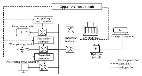
Figure 1.
Topology of the off-grid wind–solar–hydrogen storage system.
2.1. Mathematical Modeling of Wind Turbines
The output power of the direct-drive permanent magnet synchronous wind turbine is related to the parameters of the wind turbine, air density, and current wind speed, and it can be expressed as
Here, represents the output power of the wind turbine, is the wind energy utilization coefficient, is the air density, is the radius of the wind rotor, and is the wind speed.
2.2. Mathematical Modeling of Photovoltaic Systems
The output current of the photovoltaic module is
Here, is the photocurrent, is the saturation current of the photovoltaic module, is the elementary charge, is the output voltage of the photovoltaic module, is the series resistance, is the ideality factor of the diode, is the number of series-connected blocks in the photovoltaic module, is the Boltzmann constant, is the operating temperature, and is the current through the shunt resistance.
2.3. Mathematical Modeling of Electrolyzers
Considering the electrolysis hydrogen production system as a DC load, the higher the input current and voltage, the higher the hydrogen production efficiency. The U-I characteristic equation of the electrolyzer is
In this equation, is the open-circuit voltage of the electrolyzer, is the activation polarization voltage, which is the voltage generated during the electrochemical reaction inside the electrolyzer, and is the ohmic polarization voltage, which is the voltage produced by the internal resistance of the electrolyzer.
The expression for the open-circuit voltage is
Here, is the inductive current, is the reversible voltage of the electrolyzer under normal operating conditions, and are the internal resistance parameters of the electrolyzer affected by temperature, and is the operating temperature of the electrolyzer. is the area of the electrolyzer.
The expression for the activation polarization voltage is
where is the gas constant, 8.314 , is the temperature of the electrolysis cell, F is the Faraday constant (F = 96,500 C/mol), is the transfer coefficient (a dimensionless number, taken as 0.25), is the current density, and is the exchange current density.
The expression for the ohmic overvoltage is
where is the current density, is the thickness of the proton exchange membrane, and is the membrane resistivity.
The expression for the hydrogen production flow rate is
where is the number of individual electrolysis cells in the electrolyzer, is the Faraday efficiency affected by the current density, and and are parameters for measuring the Faraday efficiency.
The expression for the reversible voltage of the electrolyzer under normal operating conditions is
where is the change in Gibbs free energy for the electrochemical reaction occurring in the electrolyzer under normal operating conditions (for electrochemical reactions involving water as a product, ); z is the number of electrons transferred in each chemical reaction during the electrolysis of hydrogen, which is generally taken as a fixed value of 2; and F represents Faraday’s constant, with a value of 96,500 C/mol.
2.4. Mathematical Modeling of Fuel Cells
The mathematical model of a proton exchange membrane fuel cell (PEMFC) is
where is the ion drag coefficient, is the molar mass of water, is the number of electrolysis cell units, is the area of the electrolyzer, is the thickness of the proton exchange membrane, is the diffusion rate of water in the membrane, and and are the water concentrations at the anode and cathode membrane surfaces, respectively.
The fuel cell efficiency is the power generation and elimination of a fuel cell. The ratio of the calorific value of the hydrogen consumed is calculated as follows:
2.5. Mathematical Modeling of Lithium Battery
In this paper, lithium ion batteries not only serve the purpose of peak shaving and valley filling but also act as a hybrid energy storage system in combination with fuel cells to compensate for the bus voltage of a DC microgrid in off-grid operation.
During discharge, ()
During charging, ()
In these formulas, is the actual charge of the battery, is the filtered current, is the battery current, is the constant voltage, is the polarization constant, is the battery capacity, is the exponential voltage, and is the inverse proportion of time in the exponential region.
2.6. Energy Storage Unit Converter Model
In an off-grid wind–solar–hydrogen storage DC microgrid system, the energy storage unit has two main functions. First, during periods of low electricity demand, the power generated by wind and solar sources supplies both the users and the electrolyzers used for hydrogen production. Any surplus electricity is stored in the electrochemical energy storage unit. Second, during peak electricity demand periods, when the output from wind and solar sources is insufficient to meet the load requirements, power is delivered from the electrochemical energy storage unit to the electrical load. Therefore, the electrochemical energy storage unit is equipped with a bidirectional DC/DC converter to meet its charging and discharging needs. The circuit diagram of the electrochemical energy storage unit is shown in Figure 2 [22].
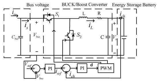
Figure 2.
Electrochemical energy storage unit converter circuit diagram.
When charging, the DC/DC converter of the energy storage battery is configured in Buck converter mode. The mathematical expression is
where is the current flowing through the battery during charging, is the reference value of the DC bus voltage, is the input current from the grid side, d is the conduction time ratio of the switch, the duty cycle, is the current input to the converter, and are the output voltage and current of the converter, respectively, represent the proportional and integral gains in the voltage loop PI controller, respectively, and represent the proportional and integral gains in the current loop PI controller, respectively.
When performing a charging operation, if the duty cycle of switch 1 is set to d, then the duty cycle of switch 2 will be 1 − d. In this case, the DC/DC converter is configured in Boost converter mode. The mathematical expression is
2.7. Energy Storage Unit Converter Model
Since the bus voltage level is 10 kV, the DC/DC converter of the hydrogen fuel cell is configured as a boost converter. When the switch is triggered and turned on, the fuel cell charges the inductor, while the capacitor discharges. When the switch is turned off due to the reverse voltage, both the fuel cell and the inductor supply energy to the bus and charge the capacitor. The inductor and capacitor boost and stabilize the output voltage, respectively.
where is the output voltage of the fuel cell, is the current of the boost circuit, is the output voltage of the boost circuit, is the duty cycle, is the conduction time of the switch, and is the off time of the switch. The structure of the fuel cell-side DC/DC converter is shown in Figure 3.
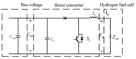
Figure 3.
Fuel cell side DCDC converter structure.
3. Control Strategy for DC Bus Voltage Stability in Wind–Solar–Hydrogen Storage DC Microgrid Systems
3.1. Traditional Double Closed–Loop Control
Figure 4 illustrates a hybrid energy storage system composed of a fuel cell and a lithium-ion battery. It is connected to the DC bus through the DC/DC converter of the fuel cell unit.
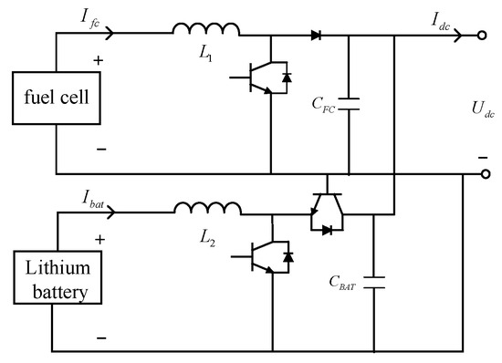
Figure 4.
Structure diagram of a fuel-cell–lithium-battery hybrid energy storage system.
In conventional control schemes, the voltage–current dual-loop control method described in Figure 5 is typically implemented. The principle of double closed-loop control voltage is to achieve fast and stable voltage regulation through the synergy of the current inner loop and the voltage outer loop. The voltage outer loop monitors the deviation between the output voltage and the voltage reference value , and it generates the current reference signal through the PI controller. The voltage inner loop tracks and adjusts the duty cycle of the switching device to achieve a fast current response.
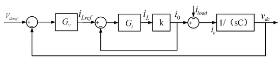
Figure 5.
DC bus double closed-loop control block diagram.
The output voltage is
where represents the closed-loop transfer function of the voltage control loop, represents the closed-loop transfer function of the current control loop, is the transfer function of the feedforward path, and is defined as the proportional factor between the port voltage and the DC bus voltage.
In the traditional dual-loop control strategy for voltage and current, the voltage of the DC bus and the current value of the fuel cell unit are first obtained through measurement. Then, the outer voltage control loop calculates the required current reference value based on these measurements. This reference value is subsequently fed into the inner current control loop, which generates the control signal to regulate the operating state of the DC/DC converter. This ensures that the output voltage and current can be tracked according to their respective reference values.
3.2. Current Feedforward Control Based on ESO and Adaptive Backstepping
The traditional dual-loop control has a relatively slow dynamic response, making it difficult to adapt to rapid load changes and power source fluctuations. To address this issue, this paper adopts a current feedforward control component. This control component is applied in the control architecture of the DC/DC converter, and its block diagram is shown in detail in Figure 6. The principle of current feedforward control is to directly detect the change of voltage or load current and adjust the control quantity in advance through the feedforward channel to offset the influence of the disturbance on the output voltage .
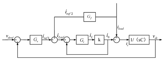
Figure 6.
DC bus voltage double closed-loop control block diagram.
Referring to the current feedforward and dual-loop control model in Figure 6, the DC bus voltage generated by the DC/DC converter can be expressed by Equation (18).
where is the transfer function of the feedforward path.
However, in practical applications, the current inner-loop control is not sensitive enough to system parameter changes and struggles to adapt to the strong nonlinearity and uncertainties in the power grid. Therefore, introducing adaptive backstepping control can utilize this estimated information to design control laws, thereby enhancing the system’s speed of response to bus voltage changes and effectively suppressing the impact of disturbances and parameter variations on system performance. This paper proposes a current feedforward control method based on the extended state observer (ESO) and adaptive backstepping.
The extended state observer can monitor and estimate external disturbances and other uncertainties in real time, rapidly tracking each state variable, thereby allowing the system analysis to be approximated as linear.
The expression for an nth-order nonlinear system is shown as follows:
where represent the system state variables that can be directly measured, represents the external disturbances suffered by the system, which have uncertain characteristics, represents the control input of the system, and b is the gain coefficient of the control input. Let , and then the state expression of the standard structure of Equation (19) is shown as follows:
By denoting the nonlinear part and the disturbance of the system in the equation as , then .
Thus, Equation (20) can be expressed as
Following the design philosophy of incorporating dynamic compensation parameters into the extended state observer (ESO) for nonlinear systems, a corresponding ESO is constructed for the system described by Equation (21):
In the above equation, is a nonlinear function related to the error. By selecting appropriate values for k and the function , the state variables and extended states in Equation (21) can be estimated effectively.
The core idea within the adaptive backstepping control strategy is to utilize the recursive design framework of backstepping to address the stability and tracking issues of nonlinear systems, while incorporating adaptive mechanisms to deal with uncertainties in system parameters and external disturbances. In adaptive backstepping control, the system is decomposed into multiple subsystems. Designers recursively design virtual control laws and/or state transformations for each subsystem to ensure that the performance metrics (such as the stability and tracking error) of each subsystem meet the predetermined requirements. At the same time, the adaptive mechanism allows the controller to dynamically adjust the control parameters to adapt to parameter variations and environmental interferences that may occur during system operation, thereby enhancing the robustness and adaptability of the system.
The design of the extended observer completes the observation of the nonlinear part of the system shown in Equation (20). Next, an adaptive backstepping controller is designed for the system shown in Equation (20), which is divided into the following five steps.
- 1.
- After applying the adaptive backstepping control, it is assumed that . The system error is defined as
The dynamic equation of the system error is
- 2.
- Selecting the Lyapunov function,
Taking the derivative yields
Treat as an input quantity,
At this point, reaches a negative definite form. By introducing a virtual control input , it can be expressed as
- 3.
- Then, we define the second error as
Substituting Equation (29) into Equation (24) yields
Then,
Here, represents the interconnection term. The subsequent dynamic equation for handling the error is
The estimated error is
- 4.
- Construct a new Lyapunov function,where is the parameter adjustment rate. Taking the derivative with respect to yields
- 5.
- The control law of the system is
The parameter update rate is
3.3. A Voltage Stabilization Strategy for a Power Spring DC Microgrid Bus Based on Adaptive Fuzzy Control
In the electrolysis unit, an adaptive fuzzy control-based power spring is introduced. By adjusting the power consumption and terminal voltage of the electrolyzer, the bus voltage can be regulated. The equivalent circuit of the power spring is shown in Figure 7.
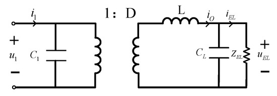
Figure 7.
Equivalent circuit diagram of the power spring.
Here, represent the input voltage and current, respectively, are the terminal voltage and current of the electrolyzer, respectively, L is the filter inductance, are the input and output capacitors, respectively, and D is the duty cycle of the controller.
The core principle of the adaptive fuzzy control power spring is to dynamically adjust the power of controllable loads such as electrolytic cells through fuzzy logic, and its input is the bus voltage deviation and deviation change rate. The output variable is the power adjustment of the electrolytic cell. The control block diagram is shown in Figure 8.
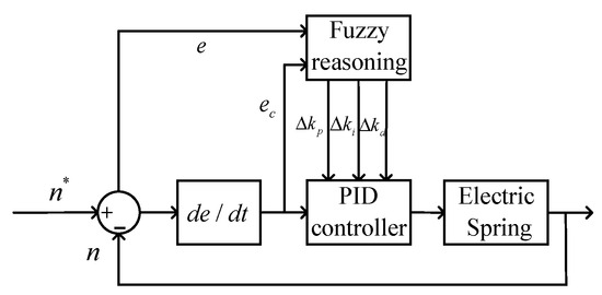
Figure 8.
Block diagram of adaptive fuzzy control.
At this point, the outputs of the PID controller are
In this equation, are the output values adjusted by fuzzy reasoning, while are the original values outputted by the PID controller. The fuzzy control rules are shown in Table 1.

Table 1.
Fuzzy control rules.
4. Results of the Experiment
This paper focuses on researching system optimization and coordinated control for the Ningbo Cixi hydrogen–electric coupling DC microgrid demonstration project. The example uses an integrated energy management system to monitor and schedule the operation of all the subsystems. Smart DC converters are employed as the main control devices in the bottom layer to regulate the operation of each subsystem. The system is powered primarily by renewable energy sources such as wind and solar power, with a kilovolt DC bus as the backbone network framework. It constructs an integrated microgrid system that combines wind, solar, energy storage, hydrogen, and charging functions. Figure 9 shows the electrical wiring diagram of the system, and the hydrogen system schematic is shown in Figure 10.
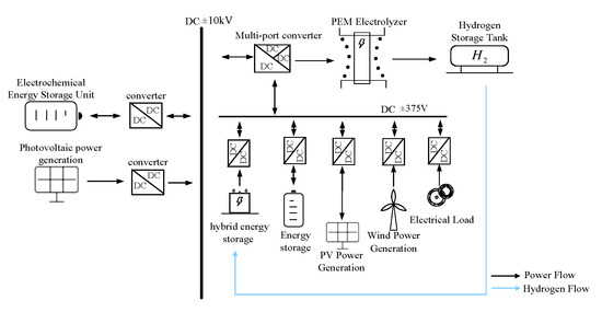
Figure 9.
Electrical system diagram.
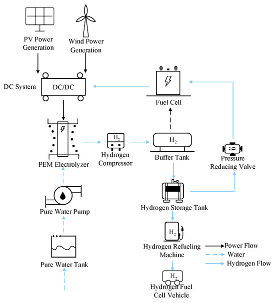
Figure 10.
Diagram of the hydrogen chain system.
4.1. Simulation Analysis of the Current Feedforward Control Strategy Based on ESO–Adaptive Backstepping
A model of an off-grid DC microgrid system with wind, solar, energy storage, and hydrogen was built in the simulation software. An extended state observer (ESO) and adaptive backstepping control were added to the DC/DC converter side, which is composed of fuel cells, electrochemical energy storage, and wind and solar power output. The output of the ESO–adaptive backstepping control was used as the reference current input to the current inner loop. In the case of DC bus voltage fluctuations, the DC/DC converter can achieve a rapid response and precise control of the current by adjusting the set current value, thereby quickly tracking the new current command. In the Ningbo Cixi hydrogen–electric coupling DC microgrid, the bus voltage is 10 kV.
To verify the control effect, two distinct operating conditions were established.
Condition 1: The system operates under normal conditions, with the standard operating parameters set at a fan speed of 8 m/s and a light intensity of 1200. Figure 11a illustrates the bus voltage curve under the improved control strategy, while Figure 11b depicts the bus voltage curve under the traditional control strategy. It is evident that, during normal system operation, the current feedforward control strategy based on ESO–adaptive backstepping achieves voltage stability with virtually no overshoot. Compared to the traditional control strategy, the time required to reach stability is reduced by 78.1%.
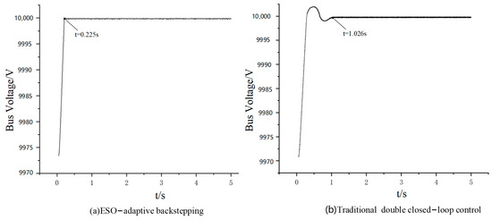
Figure 11.
Bus voltage waveforms during normal operation.
Figure 12 is the dynamic response comparison diagram of the normal operation of the system under the two control modes. It can be seen that the improved control strategy voltage waveform is more stable.
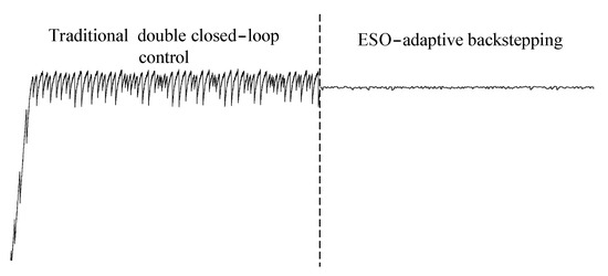
Figure 12.
Partial comparison of the system dynamic response.
Condition 2: External environmental changes occur, with the wind speed increasing from 8 m/s to 12 m/s at 0.5 s and the light intensity decreasing from 1200 to 800 at 2 s. Under the traditional control strategy, the system takes 3.43 s to re-establish stability, whereas with the improved control strategy, the system achieves stability again in 2.33 s. This demonstrates a 32.1% reduction in the voltage settling time during environmental transients compared to conventional methods. When the external environment changes, the bus voltage waveform is shown in Figure 13.
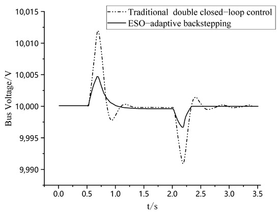
Figure 13.
The transient process of the DC bus voltage under external environmental changes.
4.2. Simulation Analysis of the Power Spring Control Strategy Based on Adaptive Fuzzy Control
Considering the demand side, a power spring based on adaptive fuzzy control is proposed and will be verified in simulations. A load of 700 kW is added to the system at 1 s. Figure 14 shows the change in the bus voltage after the controllable load compensation is applied. Table 2 records the time it takes for the system to reach stability under different control strategies.
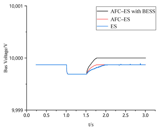
Figure 14.
Voltage change in the DC bus before and after controllable load compensation.
Table 2.
Comparative performance metrics under steady-state operation.
The power spring based on adaptive fuzzy control at the controllable load end can compensate for the bus voltage. However, due to the limited capacity of controllable loads such as electrolyzers, the bus voltage cannot be maintained within the rated standard value range. To address this issue, this paper proposes using the electrolyzer in combination with a battery energy storage system (BESS) to increase the capacity of the controllable load, thereby enabling it to compensate for the bus voltage beyond the limit and restore it to near the rated value. Analysis of the graphical data demonstrates that the electric spring (ES) with adaptive fuzzy control reduces the voltage recovery time by 26% under load disturbance conditions. Furthermore, the integrated fuel-cell–electric-spring (AFC-ES) system with electrochemical energy storage ensures full restoration of the bus voltage to its nominal value.
4.3. Simulation Analysis of Off-Grid Wind–Solar–Hydrogen Energy Storage DC Microgrid
The following four control strategies were applied in the simulation analysis to verify the effectiveness of the proposed control strategies. The configurations of different control strategies are shown in Table 3.
Table 3.
Simulation configurations.
A load disturbance scenario is now set up. At t = 2 s, a load of approximately 700 kW is added to the wind–solar–hydrogen energy storage DC microgrid system, and this load is removed after 0.3 s. Figure 14 shows the bus voltage waveforms under different control strategies for this simulation scenario. The bus voltage waveforms under different control strategies are shown in Figure 15. The maximum and minimum bus voltages under different control strategies, as well as the time it takes for the system to reach stability, are shown in Table 4.
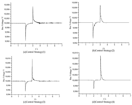
Figure 15.
Voltage variation curve of the DC bus during load disturbance.
Table 4.
Maximum and minimum DC bus voltage during load disturbance.
The hydrogen fuel cell efficiencies under the four control strategies are comparatively presented in Figure 16.
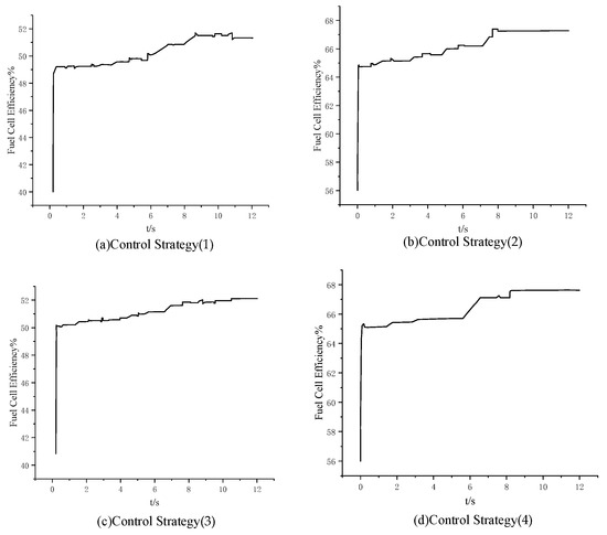
Figure 16.
Fuel cell efficiency.
As quantified in Table 5, the ESO–adaptive backstepping strategy reduces the voltage fluctuation amplitude by 10.22% and the settling time by 32.31% compared to double closed-loop control, while increasing the fuel cell efficiency from 50.07% to 65.73% through operating point optimization. The synergistic combination with the electric spring further enhances the performance, achieving 24.07% fluctuation suppression and 56.92% faster stabilization.
Table 5.
Comparative performance metrics of the control strategies.
5. Conclusions
We simultaneously controlled both the power side and the load side of the off-grid wind–solar–hydrogen energy storage DC microgrid system, enabling the system to dynamically respond to load changes and other uncertainties, thereby enhancing its robustness and improving its energy utilization efficiency. The specific conclusions drawn from the practical case verification are as follows:
- (1)
- The proposed current feedforward control strategy incorporating an extended state observer (ESO) and adaptive backstepping control, implemented on the fuel cell DC/DC converter side, demonstrates significant performance enhancements: under normal operating conditions, it reduces the bus voltage stabilization time by 78.1% compared to conventional double closed-loop control, fulfilling the transient response requirements for critical power supply; moreover, during external environmental variations, the system achieves 32.1% faster stabilization than traditional double closed-loop control, confirming its enhanced capability to withstand operational uncertainties.
- (2)
- On the electrolyzer side, the proposed adaptive fuzzy-controlled electric spring (ES) reduces the voltage recovery time by 26% under load disturbance conditions, while the integrated AFC-ES hybrid system, through coordinated regulation of the fuel cells and battery energy storage, ensures precise restoration of the bus voltage to its nominal value.
- (3)
- The integrated control strategy combining extended state observer (ESO)-based adaptive backstepping and the active-fuel-cell–electric-spring (AFC–ES) system demonstrates significant performance enhancements over conventional double closed-loop control, achieving 24.07% suppression of the bus voltage fluctuations, a 56.92% reduction in the stabilization time, and a 31.88% improvement in the hydrogen fuel cell efficiency (based on the lower heating value) under load disturbance conditions.
In terms of its applications, the integrated control strategy can be extended to multi-terminal high-voltage direct current (HVDC) grids, such as offshore wind power-to-hydrogen systems, as well as industrial complexes with high requirements for the power supply quality and reliability. These improvements enhance the system stability and reduce the voltage fluctuations, thereby supporting data centers, manufacturing plants, and medical facilities that demand precise power supply conditions.
From the perspective of industrial transformation, this technology offers viable hydrogen-based power supply and distribution solutions for high-energy-consuming industries such as steel and chemicals, thereby reducing CO2 emissions. Moreover, the system’s rapid response characteristic, which represents a 56.9% improvement in the disturbance recovery time, can match the sudden power demand changes of electric vehicle fast-charging stations. This provides key technological support for the construction of “electricity–hydrogen”-coupled infrastructure in the transportation sector.
Economically, the 31.88% increase in fuel cell efficiency can reduce the hydrogen consumption. The 22.7% reduction in the voltage fluctuation range can extend the lifespan of equipment and decrease the frequency of equipment replacement.
Future research will proceed in the following four areas.
Hardware Implementation and Validation: The computational efficiency of the ESO–adaptive backstepping control algorithm will be validated on a 10 kV/1 MW physical test platform.
Long-Term Stability Assessment
Long -Term Stability Assessment: The long-term stability of the system will be evaluated by considering factors such as component aging, environmental variations, seasonal changes in renewable energy generation, and the capacity degradation characteristics of electro-hydrogen hybrid energy storage. This comprehensive assessment will ensure that the system’s performance does not significantly deteriorate over extended periods of operation.
Integration with Real-Time Monitoring Systems
Integration with Real-Time Monitoring Systems: Future research should explore the development of intelligent monitoring frameworks that provide continuous feedback on system performance, enabling real-time adjustments to control parameters. This integration can leverage emerging technologies such as the Internet of Things (IoT) and machine learning algorithms to enhance the predictive maintenance capabilities and dynamically optimize the system operation.
Economic and Environmental Impact Assessment
Economic and Environmental Impact Assessment: A comprehensive evaluation of the economic and environmental benefits of the proposed control strategy is essential. This includes assessing the cost savings associated with reduced equipment maintenance and extended equipment lifespans, as well as quantifying the environmental impact of reduced CO2 emissions through efficient hydrogen utilization. Such assessments will provide a holistic view of the benefits.
Author Contributions
Conceptualization, J.C. and J.M.; methodology, J.C. and J.M.; software, J.M.; resources, J.C. and G.B.; data curation, X.H.; writing—original draft preparation, J.M.; writing—review and editing, J.C. and J.M.; supervision, X.H. All authors have read and agreed to the published version of the manuscript.
Funding
This research was funded by the National Natural Science Foundation of China, grant number. 62476153.
Data Availability Statement
The original contributions presented in this study are included in the article; further inquiries can be directed to the corresponding author.
Conflicts of Interest
The authors declare no conflicts of interest.
References
- Wang, Q. Simulation and Performance Analysis of Wind-Solar Hydrogen Production System. Master’s Thesis, South China University of Technology, Guangzhou, China, 2021. [Google Scholar]
- Shao, C.; Hu, R.; Yu, J.; Wang, M. Dynamic Control Simulation Model of Wind-Solar-Hydrogen Storage System Considering Charge and Hydrogen Storage States. China Electr. Power 2024, 57, 109–124. [Google Scholar]
- Ma, T.; Pei, W.; Yang, Y.; Xiao, H.; Tang, C.; Hua, W. A coordinated operation method of wind-PV-hydrogen-storage multi-agent energy system. Glob. Energy Interconnect. 2024, 7, 446–461. [Google Scholar] [CrossRef]
- Salama, H.S.; Magdy, G.; Bakeer, A.; Vokony, I. Adaptive coordination control strategy of renewable energy sources, hydrogen production unit, and fuel cell for frequency regulation of a hybrid distributed power system. Prot. Control Mod. Power Syst. 2022, 7, 1–18. [Google Scholar] [CrossRef]
- Li, R.; Jin, X.; Yang, P.; Sun, X.; Zhu, G.; Zheng, Y.; Zheng, M.; Wang, L.; Zhu, M.; Qi, Y. Techno-economic analysis of a wind-photovoltaic-electrolysis-battery hybrid energy system for power and hydrogen generation. Energy Convers. Manag. 2023, 281, 116854. [Google Scholar] [CrossRef]
- Jing, T.; Chen, G.; Wang, Z.; Xu, P.; Li, G.; Jia, M.; Wang, Y.; Shi, J.; Li, M. Review of Wind-Solar Complementary Power Generation Coupled with Hydrogen Energy Storage Systems. China Electr. Power 2022, 55, 75–83. [Google Scholar]
- Hasanpour, S.; Lee, S.S. A new quadratic DC/DC converter with ultra-high voltage gain. IEEE Trans. Power Electron. 2024, 39, 8800–8812. [Google Scholar] [CrossRef]
- Mumtaz, F.; Yahaya, N.Z.; Meraj, S.T.; Singh, N.S.S.; Rahman, M.S.; Hossain Lipu, M.S. A high voltage gain interleaved DC-DC converter integrated fuel cell for power quality enhancement of Microgrid. Sustainability 2023, 15, 7157. [Google Scholar] [CrossRef]
- Gao, W.H.; Zhao, X.Y. Voltage Fluctuation Suppression of DC Microgrid Bus with Composite Energy Storage. Electr. Autom. 2020, 42, 72–75. [Google Scholar]
- Zhang, C. Bus Voltage Control and Energy Management of Independent DC Microgrid Based on Hybrid Energy Storage. Master’s Thesis, Tianjin University of Technology, Tianjin, China, 2023. [Google Scholar]
- Wang, Q.; Yuan, Z.; Wang, W.; He, S. Solid-State Transformer for DC Microgrid and Its VSG Control. Mod. Electron. Tech. 2022, 45, 80–85. [Google Scholar]
- Ghosh, S.K.; Roy, T.K.; Pramanik, M.A.H.; Sarkar, A.K.; Mahmud, M.A. An energy management system-based control strategy for DC microgrids with dual energy storage systems. Energies 2020, 13, 2992. [Google Scholar] [CrossRef]
- Chen, Q.; Tian, X.; Wang, Q. Collaborative Control Strategy for DC Microgrid Clusters Based on Adaptive Droop Control. J. Electr. Eng. 2024, 1–8. Available online: http://kns.cnki.net/kcms/detail/10.1289.TM.20230728.1744.006.html (accessed on 18 December 2024).
- Guo, B. Stability Analysis and Control Strategy Research of Off-Grid Wind-Solar-Hydrogen DC Microgrid. Master’s Thesis, China University of Petroleum, Qingdao, China, 2022. [Google Scholar]
- Keskin, R.; Aliskan, I.; Daş, E. Robust fixed-order H∞ controller synthesis for multi-phase converters with input voltage feed-forward. J. Frankl. Inst. 2023, 360, 8251–8276. [Google Scholar] [CrossRef]
- Li, S.; Lu, H.; Li, J.; Zheng, T.; He, Y. Fractional-Order Sliding Mode Controller Based on ESO for a Buck Converter with Mismatched Disturbances: Design and Experiments. IEEE Trans. Ind. Electron. 2025, 1–12. [Google Scholar] [CrossRef]
- Yang, Y.; Huang, J. Bus Voltage Control of DC Microgrid Based on Differential Flatness Theory. Proc. CSU-EPSA 2022, 34, 66–73. [Google Scholar]
- Liu, P.; Shi, M.; He, L.; He, N.; Chen, W. Bus Voltage Stability Control of Medium and Low Voltage DC Distribution Networks. Electr. Power Autom. Equip. 2022, 42, 120–125. [Google Scholar]
- Liao, J.; Zhou, N.; Huang, Y.; Wang, Q. Unbalanced voltage suppression in a bipolar DC distribution network based on DC electric springs. IEEE Trans. Smart Grid 2019, 11, 1667–1678. [Google Scholar] [CrossRef]
- Zhang, J.; Wu, Z.; Lu, X.; Wang, C. Research on Coordinated Control Strategy of “PV-Energy Storage-Direct Current-Flexibility” System Considering DC Electric Spring. Distrib. Util. 2023, 40, 82–92. [Google Scholar]
- Li, F.; Liu, C.; Zhang, J.; Guo, G.; Chen, Y.; Wei, X. Resilience optimal control strategy of microgrid based on electric spring. Energy Rep. 2023, 9, 236–245. [Google Scholar] [CrossRef]
- Wang, H. Research on the Control of Bidirectional DC-DC Converter on the Energy Storage Side of Microgrid. Master’s Thesis, Anhui University of Science and Technology, Huainan, China, 2024. [Google Scholar]
Disclaimer/Publisher’s Note: The statements, opinions and data contained in all publications are solely those of the individual author(s) and contributor(s) and not of MDPI and/or the editor(s). MDPI and/or the editor(s) disclaim responsibility for any injury to people or property resulting from any ideas, methods, instructions or products referred to in the content. |
© 2025 by the authors. Licensee MDPI, Basel, Switzerland. This article is an open access article distributed under the terms and conditions of the Creative Commons Attribution (CC BY) license (https://creativecommons.org/licenses/by/4.0/).