Review

Bidirectional DC-DC Converter Topologies for Hybrid Energy Storage Systems in Electric Vehicles: A Comprehensive Review

1
Department of Electrical and Electronic Engineering, The Hong Kong Polytechnic University, Hong Kong SAR, China
2
FEMTO-ST Institute, CNRS, UTBM, Université Marie et Louis Pasteur, F-90000 Belfort, France
3
Shenzhen Research Institute, The Hong Kong Polytechnic University, Shenzhen 518000, China
4
State Grid Energy Research Institute, Beijing 102209, China
*
Author to whom correspondence should be addressed.
Energies 2025, 18(9), 2312; https://doi.org/10.3390/en18092312
Submission received: 11 March 2025 / Revised: 22 April 2025 / Accepted: 29 April 2025 / Published: 1 May 2025

Abstract

:
Electric Vehicles (EV) significantly contribute to reducing carbon emissions and promoting sustainable transportation. Among EV technologies, hybrid energy storage systems (HESS), which combine fuel cells, power batteries, and supercapacitors, have been widely adopted to enhance energy density, power density, and system efficiency. Bidirectional DC-DC converters are pivotal in HESS, enabling efficient energy management, voltage matching, and bidirectional energy flow between storage devices and vehicle systems. This paper provides a comprehensive review of bidirectional DC-DC converter topologies for EV applications, which focuses on both non-isolated and isolated designs. Non-isolated topologies, such as Buck-Boost, Ćuk, and interleaved converters, are featured for their simplicity, efficiency, and compactness. Isolated topologies, such as dual active bridge (DAB) and push-pull converters, are featured for their high voltage gain and electrical isolation. An evaluation framework is proposed, incorporating key performance metrics such as voltage stress, current stress, power density, and switching frequency. The results highlight the strengths and limitations of various converter topologies, offering insights into their optimization for EV applications. Future research directions include integrating wide-bandgap devices, advanced control strategies, and novel topologies to address challenges such as wide voltage gain, high efficiency, and compact design. This work underscores the critical role of bidirectional DC-DC converters in advancing energy-efficient and sustainable EV technologies.

1. Introduction

With the global expansion of renewable energy sources (RES), solutions that leverage renewable electricity to decarbonize end-use energy have garnered significant attention [1]. The continuous use of fossil fuels, including oil and natural gas, along with the rising levels of greenhouse gas emissions, has caused serious consequences for the climate and environment [2]. As the global population grows, incomes rise, and an increasing number of people gain access to cars, trains, and aeroplanes [3], it is anticipated that worldwide transportation demand will surge in the coming decades [4]. In its Energy Technology Perspectives report, the International Energy Agency (IEA) projects that by 2070, global transportation (measured in passenger kilometres) will double, car ownership will rise by 60%, and both passenger and freight aviation demand will increase threefold. Collectively, these factors are expected to lead to a substantial rise in transportation-related emissions [5].
Transportation accounts for roughly one-fifth of global CO2 emissions, or 24% if we consider only energy-related CO2 emissions [6]. Every year, the urgency to cut global greenhouse gas emissions becomes more pressing, yet they persist at unsustainably high levels [7]. Meeting international climate goals requires emissions to reach their peak as soon as possible and then decline swiftly to achieve net-zero levels in the latter half of this century. Since the energy sector is responsible for the majority of global CO2 emissions, transitioning to cleaner energy systems has become a critical priority [4]. Although the COVID-19 crisis led to a decline in global CO2 emissions in 2020, this reduction will be fleeting unless structural changes are made to the energy system.
Significant technological innovations, however, can help offset the growth in demand. As the world transitions to low-carbon power sources, the rise of electric vehicles (EV) offers a viable solution for reducing passenger car emissions [4]. This is reflected in the IEA’s Energy Technology Perspectives report, which outlines a “Sustainable Development Scenario” to achieve net-zero global energy-related CO2 emissions by 2070 [8]. The visualization of this optimistic scenario highlights the pathways for various elements of the transportation sector. It reveals that some sub-sectors could achieve decarbonization within decades through electrification and hydrogen technologies. The IEA scenario envisions the phased elimination of motorcycle emissions by 2040, railway emissions by 2050, and small truck emissions by 2060 [5]. Although emissions from cars and buses are not expected to be fully eradicated until 2070, many regions, including the European Union, the United States, China, and Japan, are projected to phase out conventional vehicles as early as 2040 [9].
According to the different sources of driving power, EVs are generally divided into the following four categories [10]: Hybrid Electric Vehicles (HEV), Battery Electric Vehicles (BEV), Fuel Cell Electric Vehicles (FCEV), Plug-in Hybrid Electric Vehicle (PHEV) [11]. This definition does not mention Extended Range Electric Vehicles (EREV). EREV is a subset of new energy vehicles, aiming to combine the advantages of HEVs and BEVs and provide a solution to reducing tailpipe emissions whilst providing satisfactory driving range compared with traditional internal combustion engine (ICE) vehicle counterparts [12].
  • Hybrid Electric Vehicles [7]: HEV includes gasoline-electric hybrid vehicles and plug-in gasoline-electric hybrid vehicles, which utilize two or more energy sources to generate kinetic energy. These vehicles often feature dual or multiple propulsion systems, such as a gasoline engine combined with an electric motor to enable their operation.
  • Battery Electric Vehicles [13]: BEV are fully powered by batteries, relying exclusively on electrical energy to drive their motors, with an inverter used to transfer power. They lack an engine, fuel tank, or intake and exhaust systems. This type of vehicle produces no air pollution.
  • Fuel Cell Electric Vehicles [14]: FCEV are a type of electric vehicle equipped with a fuel cell power system that converts the chemical energy of fuel into electrical energy, with hydrogen being the most commonly used fuel. Stored high-pressure hydrogen reacts with oxygen from the environment to produce water and electricity while releasing heat.
EVs comprise five fundamental systems that facilitate their operation [15]. These systems include:
  • Power system: This is comprised of a power converter, drive motor, controller, and transmission system.
  • Body system: This includes wheel frames, fasteners, LED lights, cooling components, audio, and other equipment.
  • Vehicle electrical systems: This includes highly integrated components such as self-driving systems, central control systems, and vehicle entertainment systems, which share substantial subsystems and hardware resources to achieve seamless functionality.
  • Battery system: Including secondary batteries and fuel cells, this consists of positive and negative electrode materials, battery pack structural parts, etc. It accounts for the largest share of costs, followed by the powertrain and body/chassis systems—together, they make up 80% of the total vehicle cost.
  • Charging system: This system features charging piles, power cords, charging guns, and power supply components.
The Hybrid Energy Storage System (HESS), as an advanced energy storage solution, has been widely adopted in the field of EV, primarily to simultaneously meet the demands for power density and energy density, optimize energy management, and enhance both system efficiency and lifespan [16]. By integrating various energy storage devices—such as fuel cells (FC), power batteries, and supercapacitors (SC)—HESS enables the rational distribution of energy under different operating conditions, thereby improving vehicle power response and energy utilization efficiency [17]. A typical HESS [18] for EVs is illustrated in Figure 1.
In FCEV, as depicted in Figure 1a, the FC serves as the primary energy source, delivering the vehicle’s average power output to ensure a stable energy supply [19]. However, due to the inherently slow dynamic response of FC, they struggle to meet the rapid power demands of transient conditions such as acceleration and deceleration. To address this, the system incorporates a SC as an auxiliary energy storage unit [20]. When the vehicle undergoes sudden changes in operating conditions, the SC provides instantaneous power, ensuring a swift response to dynamic power demands. The FC is connected to the DC bus via the unidirectional DC-DC converter, Which facilitates voltage matching and power decoupling. In contrast, the SC is linked through a bidirectional DC-DC converter that allows for rapid bidirectional energy flow and enhances the system’s power stability.
Figure 1b illustrates the HESS architecture in Plug-in Hybrid Electric Vehicles (PHEV) [21]. Unlike FCEV, this system primarily relies on the power battery to provide a stable average power output while incorporating the SC to compensate for transient power fluctuations. The power battery, connected to the DC bus via a bidirectional DC-DC converter, not only ensures a steady energy supply but also facilitates energy recuperation during braking and deceleration, thereby improving overall energy efficiency [22]. Similarly, the SC, also linked via a bidirectional DC-DC converter, delivers additional instantaneous power during acceleration and absorbs regenerative energy during braking, achieving highly efficient energy management [23].
Figure 1c presents the HESS architecture in Fuel Cell Plug-in Hybrid Electric Vehicles (FC-PHEV) [21], which integrates both FC and power batteries. In this setup, the battery functions as the main power source, with the FC operating as a supplementary unit. When the powertrain demand is minimal, the power battery independently supplies energy; during rapid power fluctuations, the SC delivers instantaneous energy; and when the power battery lacks sufficient energy, the FC activates to maintain the energy supply [24]. Additionally, the SC not only supports the powertrain with instantaneous power but also stores regenerative braking energy, which further enhances energy utilization efficiency.
Figure 1d illustrates the HESS architecture in Hybrid Electric Vehicles (HEV) [25]. This category of EVs combines an internal combustion engine (ICE) with an electric motor, utilizing the ICE to generate electricity and supplement the power battery’s charging process. As a result, HEV offers an advantage in extended driving range compared to conventional BEV [26]. The energy generated from the ICE can be efficiently utilized, reducing dependency on external charging infrastructure and improving overall fuel efficiency. However, the operation of HEV is contingent on fuel availability and the efficiency of energy management systems [27]. This means that under specific driving conditions, HEV can operate either in electric-only mode or with the support of the ICE, depending on the power demand. Furthermore, HEV remains compatible with regenerative braking systems, ensuring energy recovery and improved efficiency under diverse driving conditions [28].
In conclusion, HESS, by integrating FC, power batteries, SC, and solar energy, demonstrates remarkable advantages in the EV sector, providing effective solutions for enhancing energy efficiency, optimizing power performance, and extending driving range. In HESS, the bidirectional DC-DC converter is pivotal in energy management. It primarily facilitates power distribution among different energy sources and ensures voltage matching. While FC and power batteries predominantly supply the system’s average power demand, SC delivers peak power and instantaneous energy during dynamic transitions, such as acceleration, deceleration, and energy recuperation, to ensure a rapid system response [29].
However, due to the inherent mismatch between the output voltage of SC and the vehicle’s DC bus voltage, the converter is essential for voltage regulation, ensuring efficient energy transfer and stable system operation [30]. During charging and discharging, the terminal voltage of SC fluctuates significantly with changes in its state of charge (SOC) [31]. For instance, an SC module rated at 16.2 V may exhibit a voltage close to 16.2 V when fully charged, whereas, during discharge, it may drop to just a few volts or even lower. Conversely, vehicle load components, such as motor controllers and DC-DC converters, have strict voltage input requirements, and excessive voltage fluctuations can compromise performance [32]. As a result, in electric and hybrid vehicles, sc typically operates in conjunction with power batteries, assisting in energy recuperation and transient power compensation [33]. In such applications, the sc’s voltage must be properly matched with the battery system voltage to prevent energy transfer inefficiencies or system instability. Given the wide voltage variation range of SC—from high voltages at full charge to significantly lower levels at depleted states—the DC-DC converter must be capable of stable operation across a broad input voltage range, which particularly maintains high-efficiency boost functionality even at low input voltages. Furthermore, since SC output voltages are generally lower than the vehicle’s DC bus voltage (which may be 400 V or higher), a converter is required to step up the output voltage to match the bus voltage, ensuring efficient energy transfer. To further improve the recovery of braking energy [34], the converter must maintain a stable output even under low input voltage conditions. This ensures that recuperated energy is effectively stored and redeployed to power the vehicle, thereby maximizing overall energy utilization efficiency.
This paper makes three key contributions: (1) This paper provides an extensive review of bidirectional DC-DC converter topologies for HESS in EV, categorizing them into non-isolated and isolated designs and systematically analyzing their characteristics, advantages, and application scenarios; (2) A robust evaluation framework is proposed, incorporating critical metrics such as voltage and current stress, voltage gain range, conversion efficiency, power density, and switching frequency, to facilitate the optimal design and selection of converters for HESS applications; (3) Suggestions for future research are provided, including the integration of advanced control strategies, the adoption of wide-bandgap devices, and the development of novel converter topologies to enhance system performance, reliability, and energy efficiency. We hope to follow this structure in the subsequent sections of this article: Section 2 reviews the current state of research on bidirectional DC-DC topologies in existing HESS systems. Section 3 analyzes the strengths and weaknesses of current bidirectional DC-DC converters and provides a comparative summary and evaluation. Section 4 provides an outlook on the future of bidirectional DC-DC converters. Finally, Section 5 presents the conclusions.

2. Classification of Bidirectional DC-DC Converter Topologies in HESS Systems

The existing bidirectional DC-DC converters can be broadly categorized into two types based on whether they possess electrical isolation: non-isolated bidirectional DC-DC converters and isolated bidirectional DC-DC converters.
Non-isolated topologies achieve energy transfer through direct connection, eliminating the need for magnetic components to provide electrical isolation. Although this structure cannot offer advantages like high voltage gain ratios due to the absence of a transformer, it is relatively simple in design, lightweight in topology, and avoids common issues such as magnetic interference and the additional weight and volume introduced by transformers in isolated systems [35]. These characteristics make non-isolated topologies particularly advantageous in scenarios where system size and weight are critical, such as portable devices and renewable energy systems. In contrast, isolated topologies typically achieve electrical isolation by first converting the DC voltage into high-frequency AC voltage, which couples it through a high-frequency transformer, and subsequently rectifying and filtering it back into DC voltage. The use of a high-frequency transformer provides these topologies with significant voltage gain capabilities and enhanced electrical safety, which makes them well-suited for applications requiring strict electrical isolation and high voltage gain, such as EVs and renewable energy generation systems [36]. Figure 2 illustrates a detailed classification of the mentioned DC-DC converters.

2.1. Non-Isolated Bidirectional DC-DC Topologies

With the rapid advancement of EV technology, increasingly stringent performance requirements have been placed on bidirectional converters, particularly in common-ground design between input and output, as well as power-side current ripple suppression. EV systems demand high efficiency, reliability, and low ripple characteristics from converters [37]. However, existing research on bidirectional DC-DC converter topologies based on switched inductors, switched capacitors, Z-source networks, and voltage-boost circuits remains relatively limited. In particular, studies addressing secondary boost and hybrid bidirectional DC-DC converters are scarce, which highlights significant opportunities for further research and optimization in this domain. Among the current non-isolated bidirectional DC-DC converter topologies, common structures include bidirectional Buck and Boost topologies, Buck-Boost topologies, Ćuk topologies, SEPIC topologies, interleaved parallel bidirectional topologies, three-level bidirectional topologies, voltage-mode (VM)-based bidirectional topologies, quasi-Z-source bidirectional topologies, H-bridge-based bidirectional topologies, and cascaded bidirectional topologies. Each of these topologies exhibits unique characteristics which cater to the demands of various application scenarios. However, they also face practical challenges related to efficiency, power density, cost, and adaptability. This paper focuses on the research status of the seven representative non-isolated bidirectional DC-DC topologies, providing an in-depth analysis of their operational characteristics, technical challenges, and potential applications in EV. The aim is to provide theoretical insights and technical guidance to support advancements and optimizations in this evolving field [38].

2.1.1. Topologies of Bidirectional Buck and Boost DC-DC Converters

The Basic bidirectional converter is derived from the traditional unidirectional Buck and Boost converters, with its basic topology illustrated in Figure 3a. This bidirectional topology is realized by replacing the unidirectional power switches in the Buck and Boost converters with bidirectional power switches, enabling the circuit to facilitate bidirectional power flow [39]. Specifically, in the forward operation mode ( V L to V H ), the converter operates as a Boost converter, stepping up the input voltage to a higher output voltage. Conversely, in reverse operation mode ( V H to V L ), the converter functions as a Buck converter, which steps down the high voltage to a lower output voltage suitable for the load [40]. Through this straightforward structural modification, the bidirectional Buck-Boost converter effectively accommodates power flow in both directions and has become one of the most fundamental and widely adopted topologies in bidirectional DC-DC converters. It serves as the foundation for the derivation and design of more advanced and complex topologies in this field.

2.1.2. Topologies of Bidirectional Buck-Boost DC-DC Converters

The bidirectional Buck-Boost converter can be derived from a unidirectional converter by replacing the unidirectional power switches in the traditional topology with bidirectional power switches [41]. Its basic topology is illustrated in Figure 3b. This modification enables bidirectional power flow and retains the fundamental functionality of the unidirectional Buck-Boost converter, specifically its capability to perform both Boost and Buck voltage conversion. More specifically, the bidirectional Buck-Boost converter operates in the forward mode by stepping the input voltage either up or down to the desired output voltage [42]. In the reverse mode, it regulates power flow in the opposite direction with the same flexibility. Additionally, this topology often includes the option to produce a negative output voltage, which enhances its applicability in specific scenarios [43]. By achieving bidirectional power flow while expanding its functional range, the bidirectional Buck-Boost converter has become a critical topology in the design of bidirectional DC-DC converters, which offer versatility and adaptability for a wide range of applications.

2.1.3. Topologies of Bidirectional Ćuk DC-DC Converters

The Ćuk converter, widely utilized in EVs, is renowned for its consistently stable input and output currents [44]. By modifying the traditional unidirectional Ćuk converter—replacing the power switch and diode positions with two bidirectional power switches—the topology can be extended into a bidirectional configuration, as shown in Figure 3c. This bidirectional Ćuk converter retains the core characteristics of its unidirectional counterpart and enables bidirectional power flow, which expands its applicability to a broader range of scenarios [45]. Furthermore, numerous studies have driven the development of Ćuk converters, with one of the most notable advancements being the coupled inductor version. Coupled inductor technology was initially introduced in unidirectional Ćuk converters to reduce input and output current ripple, which enhances circuit performance and efficiency [42]. This innovation was later successfully applied to bidirectional Ćuk converters, which significantly minimizes the impact of current ripple while improving overall EMI performance [46]. These advancements bolster the suitability of bidirectional Ćuk converters for high-performance applications and provide a solid foundation for further research and optimization of control strategies for bidirectional coupled inductor Ćuk converters. This is particularly critical in fields such as EVs and energy storage systems, where stringent demands for efficient energy management prevail [47].

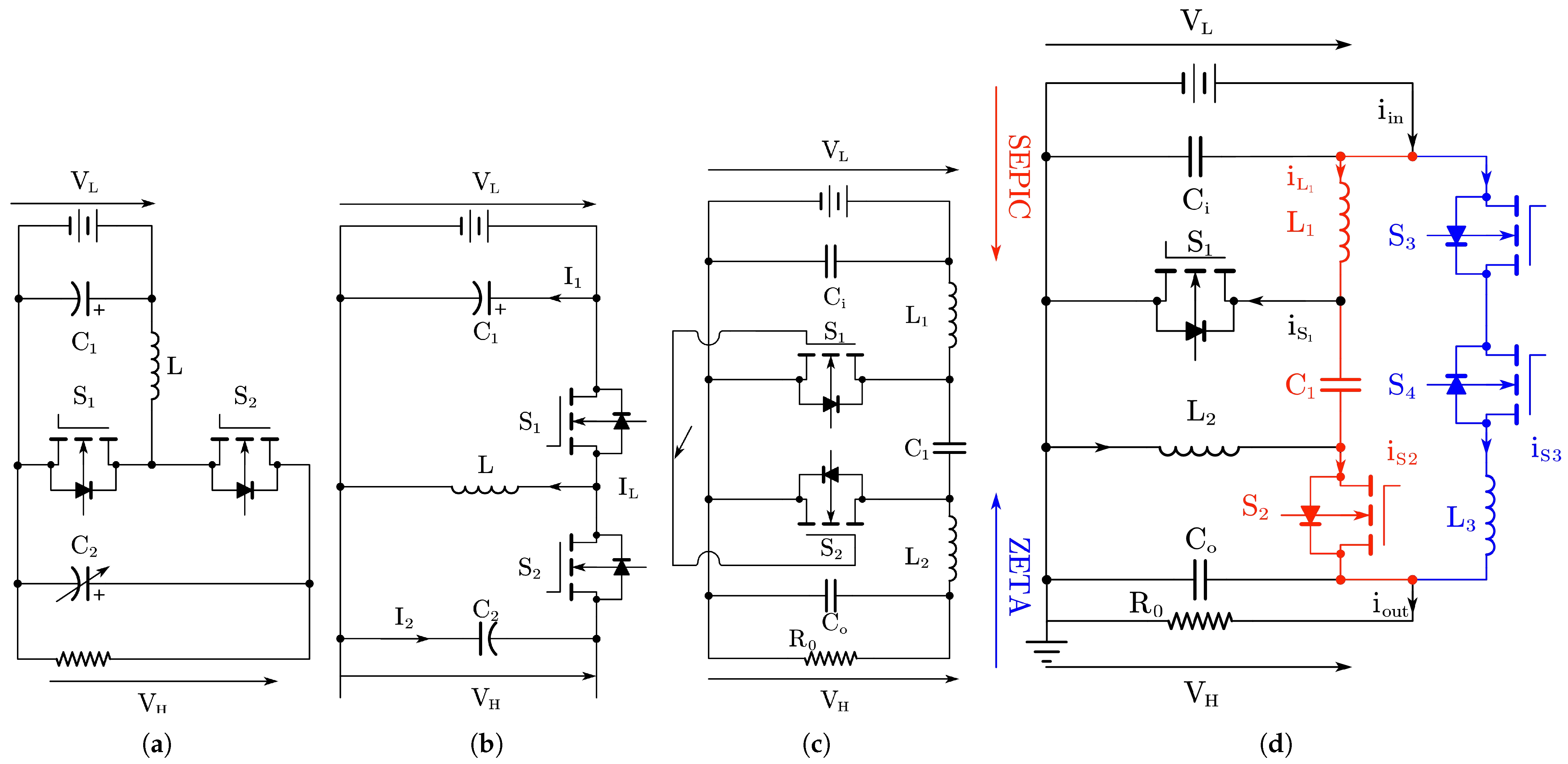
2.1.4. Topologies of Bidirectional SEPIC and Zeta DC-DC Converters

SEPIC and Zeta converters are two special types of DC-DC converters that achieve a positive output voltage by reconfiguring the components of the Ćuk converter. These two topologies leverage their unique circuit structures to accommodate both boost and buck scenarios while maintaining a positive output voltage. Figure 3d illustrates the topology of the bidirectional SEPIC/Zeta DC-DC converter [48]. When power flows from the low side to the high side, the circuit operates as a SEPIC converter, which provides a boost function [49]. Conversely, when power flows from the high-voltage side V H to V L , the circuit functions as a Zeta converter, which performs a boost operation. Additionally, the circuit features an innovative design element—highlighted in the blue branch of the diagram—that introduces a new transfer path. This design not only simplifies the power transfer process but also significantly reduces current ripple, which improves the efficiency and stability of the circuit. Such a topology performs exceptionally well in high-efficiency energy management scenarios, especially in applications requiring bidirectional power flow and sensitivity to current ripples, such as EVs, energy storage systems, and grid stabilization equipment [45].

2.1.5. Topologies of Interleaved Bidirectional DC-DC Converters

The bidirectional converter shown in Figure 4a employs interleaving technology, which significantly reduces current ripple at switching frequency through multiphase operation, thereby enabling the use of smaller EMI filters [50]. This technique is particularly well-suited for high-power-density applications, as interleaving evenly distributes the current across multiple phases, which reduces the current stress on each phase [51]. In automotive applications that rely on multiphase systems, bidirectional interleaved topologies have been extensively studied. Research has demonstrated that interleaving technology can significantly reduce the size of filters, improve dynamic response, and optimize thermal management performance [52]. This is especially critical for scenarios with high power and efficiency demands, such as EVs and energy storage systems. Moreover, some specialized structures exist in the design of interleaved converters. For instance, studies in references [53,54] propose various interleaved bidirectional topologies characterized by inductors that can be connected in either directly coupled or inversely coupled configurations. These coupled designs further reduce current ripple while improving dynamic response and efficiency [55].

2.1.6. Topologies of Three-Level Bidirectional DC-DC Converters

The topology of the three-level bidirectional DC-DC converter, as shown in Figure 4b, incorporates a three-level structure that significantly reduces the voltage stress across the power switches [56]. This design enhances system reliability and allows for the use of lower-rated power devices, which effectively reduce costs and minimise the overall system size [57]. The operating principle of the three-level bidirectional converter is based on a capacitive voltage divider, which splits the input or output voltage into two equal parts, ensuring that each switching device is subjected to only half of the total input or output voltage stress [58]. This feature is particularly crucial in high-voltage applications such as energy storage systems and EVs, as it effectively addresses the reliability and efficiency demands in high-voltage environments. In addition to reducing voltage stress, the three-level topology further improves energy conversion efficiency by minimizing switching and conduction losses [59]. Its symmetrical circuit structure ensures balanced voltage and current distribution operation, while the design of smaller passive components significantly enhances the system’s power density. Moreover, the inherent characteristics of the three-level topology reduce output voltage ripple, which plays a vital role in improving EMI performance and makes it highly advantageous in applications requiring efficient, compact designs and high reliability [37].
In recent years, significant advancements have been made in the study of three-level bidirectional DC-DC converters, particularly in the integration of advanced control strategies. Techniques such as space vector modulation and predictive control have been applied to three-level topologies to optimize switching operations and enhance dynamic performance, which achieves higher control precision and faster response times. Furthermore, research has explored the incorporation of coupled inductors and soft-switching technologies into three-level topologies to further reduce current ripple and switching losses. The use of coupled inductors effectively minimizes ripple current and improves circuit efficiency, while soft-switching techniques, by enabling zero-voltage switching or zero-current switching, significantly reduce energy losses during switching transitions. These technological innovations have drastically improved the efficiency and power density of three-level converters and enhanced their applicability in high-performance scenarios.

2.1.7. Topologies of Cascaded Bidirectional DC-DC Converters

To enhance the boost capability of DC-DC converters and reduce current stress, two or more converters can be cascaded. Figure 4c illustrates a basic cascaded non-isolated bidirectional DC-DC converter, a topology widely utilized in the field of EVs [52]. This converter consists of two bidirectional buck-boost converters connected in series. Although this cascaded configuration introduces additional components compared to a single bidirectional buck-boost converter, it achieves a significantly higher voltage gain ratio under the same switching duty cycle [60]. Moreover, through meticulous design, this topology markedly reduces the current ripple in the inductors, as well as the current stress on the switches, capacitors, and diodes, thereby improving overall circuit performance and enabling the converter to operate at higher power levels. To further minimize current fluctuations on the output side, an auxiliary capacitor [61] is incorporated into the design, enhancing both circuit stability and output quality.
The cascaded structure offers high flexibility, enabling the combination of different sub-topologies to create novel designs that inherit the advantages of each sub-topology. Table 1 presents a comparison of different cascaded structures. By leveraging such a modular approach, cascaded bidirectional DC-DC converters can meet the demands of various high-performance scenarios [45]. However, the cascaded structure also comes with certain limitations. First, the increased number of components leads to a larger overall size and higher manufacturing costs [42]. Second, the efficiency of the cascaded converter is determined by the product of the efficiencies of its individual sub-converters, which means the overall efficiency may be relatively lower, particularly if the sub-converters have low efficiency or significant losses. Additionally, the cascaded topology inevitably inherits the drawbacks of each sub-topology, which may impose certain constraints on its performance [62].

2.1.8. Topologies of Bidirectional Switched-Capacitor DC-DC Converters

Switched-capacitor units can effectively enhance the voltage gain capability of converters. Figure 4d depicts a bidirectional converter that leverages switched-capacitor units to boost the voltage conversion ratio. This converter achieves its functionality by extending the unidirectional switched-capacitor units into a bidirectional configuration [67]. In this switched-capacitor-based topology, inductors are entirely omitted, thereby eliminating the efficiency limitations associated with magnetic energy storage and the high weight of traditional inductors [68]. This design renders the converter lighter and more suitable for applications requiring high power density [69]. Despite the absence of inductors, the converter achieves continuous input current characteristics by employing two similar switched-capacitor units connected in series and operating in a phase-shifted manner. This phase-shifted operation not only smooths the input current but also reduces current ripple, thereby enhancing system stability. More importantly, the topology exhibits excellent scalability; the voltage gain ratio can be further increased by adding more switched-capacitor units, making it adaptable to applications demanding higher voltage conversion ratios. Due to its inductor-free design, this switched-capacitor-based bidirectional converter offers significant advantages such as compact size, lightweight structure, and high power density [67]. It is ideal for devices where weight and volume are critical considerations. However, the absence of inductors for energy storage and filtering can result in higher voltage stress and EMI under high-frequency switching conditions. This imposes stricter requirements on components and control strategies to ensure reliable operation. Table 2 provides an intuitive comparison of all the aforementioned types of non-isolated bidirectional DC-DC converters.

2.2. Isolated Bidirectional DC-DC Topologies

Electrical isolation is a promising approach to achieving high voltage gain by adjusting the turn ratio of the transformer windings within the converter [70]. This method is particularly suited for applications requiring a wide input voltage range and stringent load regulation. Such a design not only delivers a high voltage conversion ratio but also offers additional benefits, including electrical isolation between the input and output sides [71]. This isolation effectively safeguards sensitive loads from faults and noise interference, making it especially critical in applications with high safety requirements. Isolated bidirectional converters, in this context, have become an ideal solution for energy conversion in EVs [61]. They not only satisfy the demand for high voltage gain but also provide vital protection to ensure system safety and reliability. The following sections classify and summarize the main topologies of isolated bidirectional converters, offering deeper insights into their applicability and performance characteristics across various use cases [72].

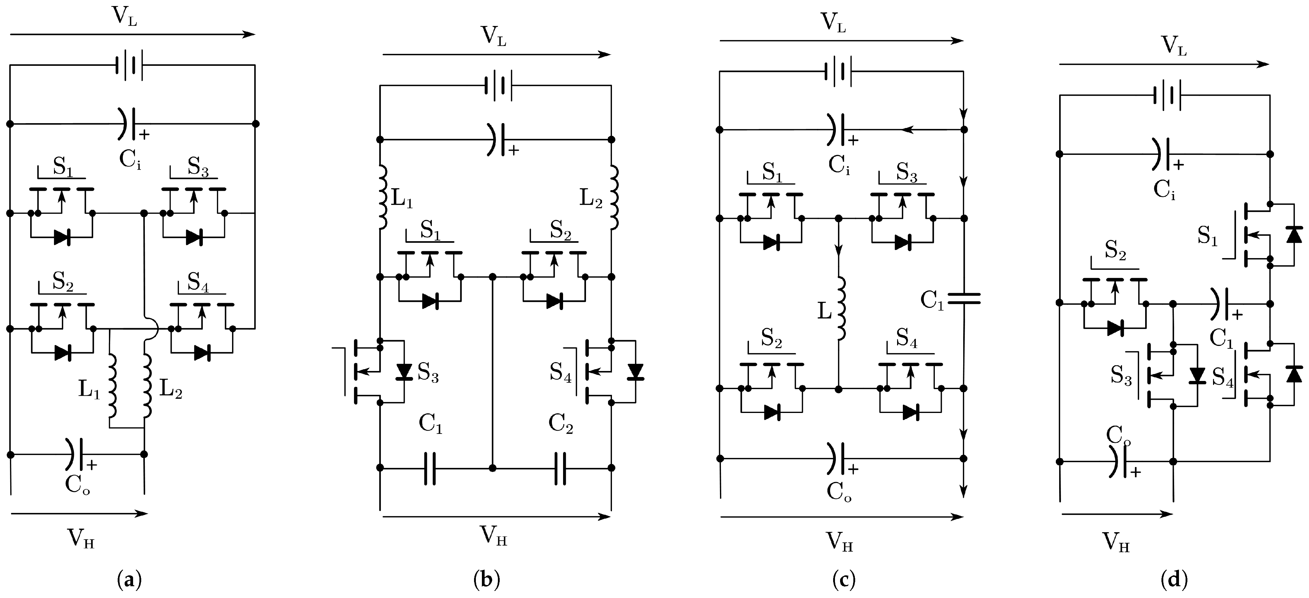
2.2.1. Topologies of Isolated Bidirectional Flyback DC-DC Converters

Various methods can be used to optimize buck-boost converters to achieve higher voltage gain without electrical isolation. However, in scenarios where magnetic isolation is required, replacing the inductor in a buck-boost converter with a transformer produces the well-known flyback converter [73]. A bidirectional isolated buck-boost converter can be derived, which is shown in Figure 5a. Typical implementations of this topology include two fundamental forms: the bidirectional flyback converter and the push-pull converter. Reference [74] introduces a bidirectional flyback converter employing a unidirectional-excitation high-frequency transformer. Due to the relatively low utilization of the transformer, this type of converter is better suited for low-power applications. The bidirectional flyback converter, with its simple structure, minimal component count, and fast dynamic response, has been widely applied in low-power scenarios requiring electrical isolation. However, in flyback converters, the high-frequency transformer must simultaneously provide electrical isolation and energy storage. As a result, the switching devices experience significant voltage and current stress, leading to considerable switching losses and reduced conversion efficiency. Similarly, in push-pull converters, the high-frequency transformer often suffers from leakage inductance, which generates substantial voltage spikes during switching events, which further increases component stress and associated losses [75].
When designing a flyback converter, special attention must be paid to transformer design to optimize performance and mitigate potential issues [76]. For instance, to suppress the voltage spikes caused by leakage inductance in the flyback transformer, a voltage clamp snubber is typically introduced to absorb excess energy, thus protecting the switching devices and reducing losses. Reference [75] further explores this topology, proposing various modifications to improve its voltage gain, thereby expanding its applicability in scenarios requiring electrical isolation and high voltage gain. Although the inherent limitations of bidirectional flyback converters make them more suitable for low-power applications, their compact topology and fast dynamic response render them indispensable in miniaturized power electronic devices that demand electrical isolation.

2.2.2. Topologies of Isolated Bidirectional Push-Pull DC-DC Converters

Its topology is depicted in Figure 5b. Similar to its unidirectional counterpart, the bidirectional push-pull converter utilizes a multi-winding transformer to facilitate power transfer and conversion [70]. Through the design of the multi-winding transformer, this topology efficiently achieves bidirectional energy transfer between different voltage levels while providing electrical isolation. This makes it particularly well-suited for applications requiring bidirectional power flow.
To further enhance the performance of this topology in high-power applications, reference [77] proposes a three-phase bidirectional push-pull converter. By extending the traditional single-phase push-pull topology into a three-phase structure, this design not only increases power transfer capability but also improves current balancing and harmonic characteristics within the system. The three-phase bidirectional push-pull converter demonstrates higher efficiency and superior dynamic performance in high-power scenarios, making it highly practical for applications such as energy storage systems. Moreover, the three-phase structure reduces current stress on switching devices and minimizes component losses, thereby further enhancing the overall reliability and efficiency of the system. These advantages position the three-phase bidirectional push-pull converter as a critical solution for high-power applications demanding both robust performance and high operational reliability [77].

2.2.3. Topologies of Isolated Bidirectional Ćuk DC-DC Converters

Based on the operating principles of the non-isolated bidirectional Ćuk converter, a new isolated bidirectional Ćuk converter has been introduced, successfully incorporating magnetic isolation advantages into the original design [78]. As shown in Figure 5c, this novel topology exhibits remarkable features, including continuous input and output currents, as well as the ability to provide electrical isolation between the input and output sides. Additionally, by leveraging the transformer’s turns ratio, the converter achieves a high voltage gain ratio, making it particularly effective in high-voltage conversion applications. Similar to the non-isolated bidirectional Ćuk converter discussed in Section 2.1.3, the performance of the circuit can be further optimized by coupling the input and output inductors. This coupling significantly reduces input and output current ripples [74], a feature that is especially critical in renewable energy systems. In such systems, minimizing current ripple enhances energy conversion efficiency, reduces component losses, and mitigates the stress on batteries and other energy storage devices, thereby extending the overall system lifespan. Furthermore, the coupled inductor design improves the system’s power density and dynamic performance, making the converter even more appealing for applications that demand high reliability and efficiency [79].
The same design principles have also been applied to develop isolated versions of bidirectional SEPIC and Zeta converters [73]. These isolated topologies combine the benefits of magnetic isolation with the functional characteristics of the original converters, further broadening their application scope across renewable energy systems, EV energy storage and charging systems, and distributed power generation systems. These isolated bidirectional converters not only meet the demands for high voltage gain and high efficiency but also provide enhanced circuit safety and system stability through their isolation features. As a result, they have become critical components in modern high-performance power electronic systems.

2.2.4. Topologies of Isolated Bidirectional Forward DC-DC Converters

Based on the principles of the unidirectional forward converter, a bidirectional forward converter was proposed in [80], with its topology shown in Figure 5d. This converter utilizes the forward structure to enable bidirectional power flow [81]. By introducing a clamping circuit, zero-voltage switching (ZVS) is achieved within the converter [82]. The incorporation of ZVS significantly reduces switching losses, improving the converter’s efficiency, which is particularly advantageous in high-frequency operation scenarios.
In [83], further optimization of the bidirectional forward DC-DC converter was explored [84]. The resonant bidirectional forward converter employs resonant principles to achieve soft-switching operation, which further reduces switching stress and electromagnetic interference (EMI) while improving system efficiency and reliability [23]. This design provides the bidirectional forward converter with greater advantages in applications requiring high power density and high efficiency.
Additionally, the literature highlights some hybrid configurations based on the forward converter, which combine the characteristics of different isolated converter topologies to meet specific application performance requirements. Examples of these hybrid topologies include:
  • Forward-Flyback Converter [63]: The primary side employs a forward topology to achieve high power transfer capability, while the secondary side adopts a flyback topology to provide excellent isolation and energy storage characteristics.
  • Push-Pull-Forward Converter [85]: The primary side utilizes a push-pull topology to deliver high power density and symmetric operation, while the secondary side adopts a forward topology to enhance dynamic response and stability.
  • Flyback-Push-Pull Converter [86]: The primary side uses a flyback topology to achieve isolation and energy storage, while the secondary side employs a push-pull topology to improve system efficiency and power transfer capability.

2.2.5. Topologies of Isolated Bidirectional DAB DC-DC Converters

Back-to-back bidirectional topologies employing high-frequency transformers for isolation represent a widely used and highly regarded technology. The design of back-to-back converters can adopt either voltage-fed or current-fed configurations, with the topology implemented in half-bridge or full-bridge arrangements [87]. Figure 6 illustrates the fundamental structure of the dual active bridge (DAB), characterized by full-bridge topologies on both sides of the high-frequency transformer [88]. As the power transfer capability of a bidirectional converter is proportional to the number of switches, this topology includes eight power switches and achieves electrical isolation through the high-frequency transformer. It is particularly well-suited for high-power applications and scenarios requiring high voltage gain, such as EV systems. While a large number of switches may lead to higher switching losses, the use of low-loss silicon carbide (SiC) [89] or gallium nitride (GaN) power switches [90] can effectively mitigate these losses and enhance overall system efficiency.
Depending on the configurations of the transformer’s two sides, the DAB topology can be further categorized into two types. In resonant DAB converters, the transformer is placed in series with a resonant circuit, leading to notable enhancements in soft-switching properties and a reduction in switching losses. A typical implementation is the LC resonator structure proposed in [87] (as shown in Figure 7a), which consists of a series inductor and capacitor, effectively suppressing DC bias. Moreover, Ref. [88] introduces magnetizing inductance into the LC resonant circuit, forming the LLC resonant structure (as shown in Figure 7b). The LLC topology supports both frequency modulation and pulse-width modulation (PWM) control strategies, effectively suppressing current harmonics, increasing the operating frequency, and reducing turn-off current, thereby further optimizing the efficiency and dynamic performance of the converter.
In contrast, for low-power applications, half-bridge topologies may offer greater advantages, such as in portable devices or small-scale energy storage systems. This topology reduces the number of power switches from eight in the DAB topology to just four. Figure 8a depicts a dual half-bridge topology for bidirectional isolated converters, with voltage-fed half-bridge structures on both sides of the transformer [91,92]. Since this topology lacks inductors, it eliminates the right-half-plane zero (RHPZ), resulting in minimum-phase characteristics that significantly simplify controller design. Reference [93] presents a converter based on the dual half-bridge topology, where the primary side employs a current-fed half-bridge structure, and the secondary side uses a voltage-fed half-bridge structure [94].
Additionally, Refs. [95,96] propose an isolated bidirectional DC-DC converter designed with a voltage-fed half-bridge topology on the transformer’s primary side and a full-bridge topology on the secondary side. This design reduces the number of switches, simplifying system complexity and cost while offering easier control compared to the DAB topology. Building on this, Ref. [97] introduces a hybrid full-bridge/half-bridge topology combined with an impedance network, significantly enhancing system performance. This approach not only improves efficiency but also enhances dynamic response, broadening its applicability to various scenarios.
In conclusion, these back-to-back bidirectional topologies, leveraging high-frequency transformer isolation, provide diverse and flexible solutions for both high-power and low-power applications. Table 3 compares the types of isolated bidirectional inverters encountered above. Their innovative designs underscore their importance and vast potential in the field of power electronics, paving the way for further advancements in modern energy systems.

2.3. Advanced Control Strategies for Optimization of Bidirectional DC-DC Converter

2.3.1. Phase-Shift Control

Phase-Shift Control (PSC) is a widely used method in bidirectional DC-DC converters to regulate power flow by adjusting the phase difference between the primary and secondary side switches. This technique enables soft-switching operation, thereby reducing switching losses and improving overall efficiency. PSC is particularly effective in high-power applications, as it minimizes EMI and enhances dynamic response during load transients [102].

2.3.2. Extended Phase-Shift Control

Extended Phase-Shift Control (EPSC) builds upon traditional PSC by introducing an additional degree of freedom in phase modulation. This method further optimizes power transfer and enables better control over reactive power. EPSC is particularly beneficial in applications requiring wide voltage gain ranges and improved efficiency under light-load conditions [103].

2.3.3. Triple Phase-Shift Control

Triple Phase-Shift Control (TPSC) extends the concept of PSC by introducing three independently adjustable phase shifts to control power flow, reactive power, and zero-voltage switching (ZVS) operation. This method ensures high efficiency even under varying load conditions and wide voltage ranges. TPSC is especially effective in converters designed for hybrid energy storage systems [104].

2.3.4. Reactive Power Control

Reactive Power Control focuses on managing the reactive power in bidirectional DC-DC converters to minimize losses and improve system stability. By dynamically adjusting the reactive power, this control strategy enhances the efficiency of power transfer and reduces the stress on components during transient operations.

2.3.5. Model Predictive Control

Model Predictive Control (MPC) employs a predictive model of the converter to optimize switching decisions in real time. By considering system constraints and predicting future states, MPC achieves high dynamic performance and precise power regulation. Its ability to handle multi-objective optimization makes it ideal for complex energy systems [105].

2.3.6. Peak Current Mode Control

Peak Current Mode Control (PCMC) regulates the peak inductor current in each switching cycle to achieve fast transient response and stable operation. It simplifies the loop compensation design and effectively limits the current in overload conditions, making it a robust choice for high-power applications [106].

2.3.7. Sliding Mode Control

Sliding Mode Control (SMC) is a nonlinear control technique that ensures robust and stable operation under parameter variations and disturbances. By driving the system towards a predefined sliding surface, SMC achieves high dynamic performance and minimizes overshoot during transients [107].

2.3.8. Zero-Voltage/Zero-Current Switching

ZVS and Zero-Current Switching (ZCS) techniques minimize switching losses by ensuring that the switching transitions occur at zero voltage or zero current. These methods significantly improve efficiency and reduce thermal stress on components, enabling higher power density designs [108].

2.3.9. Space Vector Modulation

Space Vector Modulation (SVM) is a sophisticated pulse-width modulation technique that optimizes the use of the DC bus voltage. By generating optimal switching patterns, SVM reduces harmonic distortion and enhances the overall efficiency of the converter, particularly in high-frequency applications [109].

2.3.10. Frequency Modulation

Frequency Modulation dynamically adjusts the converter’s switching frequency to achieve high efficiency across varying load conditions. This method is particularly effective in reducing switching losses under light-load conditions while maintaining stable operation [102].

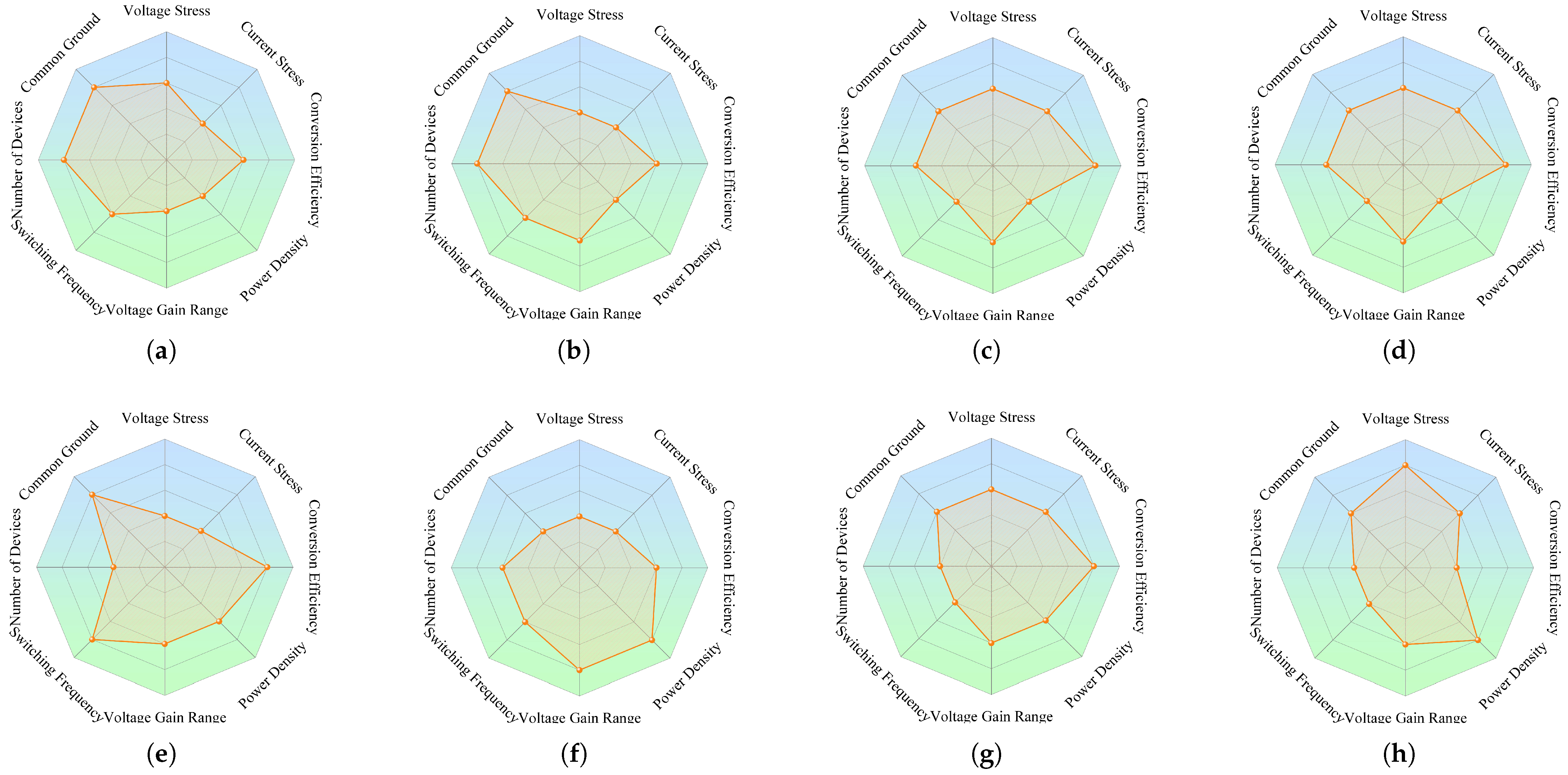
3. The Evaluation Framework for Bidirectional DC-DC Converters in HESS

The evaluation criteria for bidirectional DC-DC converters serve as critical benchmarks for assessing the advantages and limitations of various topologies, particularly in the context of hybrid energy storage systems. These systems impose stringent performance requirements on bidirectional converters, with evaluation metrics spanning multiple aspects, including thermal performance, dynamic response speed, voltage conversion ratio, input current ripple, voltage and current stress, conversion efficiency, power density, device count, voltage conversion slope, and the presence of common ground [11].
These metrics not only reflect the practical operational characteristics of converters but also directly influence the stability, efficiency, and reliability of the system. Based on these evaluation criteria, this paper selects eight of the most impactful factors to establish an innovative evaluation framework for bidirectional DC-DC converters. This framework is designed to comprehensively and systematically assess the performance of different topologies in practical applications, which offers a scientific basis for the optimal design and selection of bidirectional converters in hybrid energy storage systems.

3.1. The Evaluation Framework for Non-Isolated Bidirectional DC-DC Converters in HESS

3.1.1. Volatge Stress

Voltage stress refers to the maximum voltage a device must withstand, particularly during switching operations when the device is in the off state. Excessively high voltage stress increases the risk of device failure and necessitates the use of higher-rated, larger, and more expensive components, which could compromise system compactness and cost-effectiveness [110]. In hybrid energy storage systems (HESS) for EVs, reducing voltage stress is critical to enhancing system reliability and optimizing device selection.

3.1.2. Current Stress

Current stress is defined as the peak current flowing through the components during operation. High current stress can result in significant thermal losses, reduced efficiency, and increased wear on system components. In HESS, where power batteries and supercapacitors are central energy sources, minimizing current stress ensures prolonged device lifespan and stable operation, which is particularly crucial for applications involving frequent transient power fluctuations.

3.1.3. Conversion Efficiency

Conversion efficiency measures the ratio of output power to input power and reflects how effectively the converter utilizes energy [62]. High conversion efficiency reduces energy loss, minimizes heat generation, and improves overall system performance. In EV applications, where energy conservation is paramount, achieving high efficiency is essential to maximize battery usage and reduce cooling system requirements, particularly under dynamic operating conditions.

3.1.4. Power Density

Power density is the ratio of the converter’s power output to its physical volume. A higher power density indicates more efficient use of space, which is critical for EVs due to space constraints. Increasing power density often involves raising the switching frequency and reducing passive component sizes [111]. However, this also introduces challenges such as higher electromagnetic interference (EMI) and increased thermal management requirements.

3.1.5. Voltage Gain Range

The voltage gain range specifies the ratio between the maximum achievable output voltage and the input voltage. A wide voltage gain range is essential in HESS to adapt to the significant voltage fluctuations of supercapacitors and batteries under varying states of charge. Bidirectional DC-DC converters must maintain stable operation across this range to ensure efficient energy transfer and system stability.

3.1.6. Switching Frequency

The switching frequency represents the rate at which the converter’s switches operate. Higher switching frequencies enable the reduction of passive component sizes, contributing to improved power density and faster dynamic response. However, elevated frequencies introduce additional switching losses and EMI, requiring careful trade-offs between efficiency, thermal management, and electromagnetic compatibility in converter design.

3.1.7. Number of Devices

The number of devices in a converter topology includes active components like switches and passive components. A higher device count increases system complexity, cost, and size. Optimizing topologies to minimize the number of devices while maintaining performance is critical for EVs, where compactness, weight reduction, and cost-efficiency are prioritized.

3.1.8. Common Ground

The presence of common ground between the input and output sides of the converter simplifies the circuit design and reduces EMI caused by voltage differentials. This is particularly important in EVs, where high-frequency switching can generate significant noise [112]. A common ground design enhances system reliability, reduces interference, and ensures stable operation, especially in applications requiring high precision and safety.

3.1.9. Cases Study

(1) A Representative Case of the Three-Level Bidirectional DC-DC Converter in HESS: To provide a comprehensive understanding of the evaluation criteria outlined in Section 3.1, a case study is conducted on the three-level bidirectional DC-DC converter. This topology is particularly favored in HESS for its wide voltage gain range, low voltage stress, and compact design. However, to assess its suitability for practical applications, all evaluation metrics, including voltage stress, current stress, conversion efficiency, power density, voltage gain range, switching frequency, number of devices, and common ground, are analyzed in detail.
The three-level topology is designed to reduce voltage stress across switches by incorporating a capacitive voltage divider. This feature ensures that each switch is subjected to only half of the total input voltage, which significantly enhances the reliability of the system. Current stress is another critical factor in evaluating the performance of this topology. The three-level converter’s symmetrical design ensures balanced current distribution across the switches and capacitors, which minimizes thermal stress on individual components. This balanced operation reduces the likelihood of thermal hotspots, thereby enhancing the overall lifespan and stability of the system.
Conversion efficiency is one of the standout advantages of the three-level bidirectional DC-DC converter. Due to its reduced switching and conduction losses, this topology typically achieves an efficiency range of 90–94%, even under varying load conditions. The use of soft-switching techniques, such as zero-voltage switching (ZVS), further minimizes energy losses during switching transitions. This high efficiency not only improves energy utilization but also reduces the thermal management requirements of the system, making it particularly appealing for electric vehicle applications where energy conservation is paramount. In terms of power density, the three-level topology achieves a compact design by reducing the size of passive components, such as inductors and capacitors, through higher switching frequencies. By operating in the range of 30 kHz to 100 kHz, the converter minimizes the size of these components, resulting in a smaller and lighter system. This advantage is critical for hybrid energy storage systems, where space and weight constraints are significant considerations.
The topology’s wide voltage gain range is another important feature. It is capable of accommodating substantial voltage fluctuations in energy storage devices, such as supercapacitors and batteries, while maintaining stable operation. For example, in a typical HESS application, the supercapacitor voltage may vary from 16V to 48V, and the three-level converter can seamlessly step up or step down this voltage to match the DC bus voltage. This adaptability ensures efficient energy transfer and system stability across a wide range of operating conditions.
Despite its advantages, the three-level topology involves a relatively high number of components, including switches, diodes, and capacitors, which increases the complexity and cost of the system. However, the benefits of reduced voltage stress, improved efficiency, and enhanced reliability often outweigh these drawbacks in high-performance applications. Furthermore, the topology’s symmetrical structure simplifies the control strategy, allowing for easier implementation compared to other complex designs.
The three-level bidirectional DC-DC converter demonstrates a well-balanced trade-off between efficiency, reliability, and compactness, making it an ideal candidate for HESS applications. Its ability to address key challenges, such as wide voltage gain, high efficiency, and low voltage stress, underscores its importance in advancing energy storage technologies for new energy vehicles.
(2) A Specific Model Case on BYDBDC300-750: Taking the BYDBDC300-750 model as an example. It is a three-level bidirectional DC-DC converter that has been widely used in BYD’s leading new energy vehicles like the Tang EV and Han EV. This product serves as the pivotal energy conversion and management module between the power battery and the supercapacitor or low-voltage auxiliary battery, fully exemplifying the superiority of the three-level topology in practical hybrid energy storage systems. The module boasts a rated input voltage spanning 200 to 450 V, an output voltage range of 16 to 60 V, a maximum output power of 15 kW, and an adaptive switching frequency adjustable between 50 and 80 kHz. With a peak efficiency of 93.5%, a compact volume of 4.2 L, and a weight of 5.3 kg, it exemplifies high system integration and engineering excellence.
In real-world vehicle operation, the three-level structure employs a capacitive voltage divider network, effectively reducing the voltage withstand requirement of each main MOSFET to half of the total bus voltage. For instance, under a 450 V bus, the maximum voltage stress for a single transistor is approximately 225 V. This not only significantly enhances the safety margin of the system but also permits the adoption of medium- and low-voltage MOSFETs that feature lower conduction losses and swifter switching speeds, thereby optimizing the balance between cost and efficiency to a substantial degree. Supported by the symmetry of the topology and refined control algorithms, the current distribution achieves thermal equilibrium across switches and capacitors, mitigating localized overheating and prolonging both component lifespan and system stability. Throughout the 10–15 kW load range, the energy conversion efficiency remains steadfast between 92% and 94%. Soft-switching and synchronous rectification strategies further suppress dynamic losses, ensuring outstanding energy utilization even under frequent acceleration, regenerative braking, and other dynamic conditions. A switching frequency as high as 50–80 kHz allows for significant miniaturization of magnetic and filter components, resulting in a power density of 3.6 kW/L. This greatly liberates valuable in-vehicle space and lays a robust foundation for the flexible layout and lightweight construction of electrified vehicle platforms.
This industrial product is well-suited to accommodate wide voltage fluctuations between the power battery and the supercapacitor or 12 V low-voltage battery: the supercapacitor terminal can operate dynamically between 16 and 60 V, while the power battery side covers the full range of 200 to 450 V. Such flexibility enables the system to adeptly manage varying states of charge and load changes, achieving efficient peak power compensation and energy recuperation, thereby ensuring the robustness and economic efficiency of energy management for the entire vehicle. Although the three-level topology entails a greater number of components compared to traditional single-stage structures—integrating, for example, twelve high-performance MOSFETs, six sets of high-frequency ceramic capacitors, and several integrated magnetic devices—modular packaging and intelligent BMS/VCU communication greatly simplify system debugging and maintenance, keeping engineering complexity well within control. The product is equipped with an independent metallic shielding enclosure and an advanced liquid cooling system, guaranteeing thermal stability even under high power density. Optimized PCB layout and filtering networks ensure that its EMI margin fully complies with automotive standards, endowing it with exceptional anti-interference capabilities. Field feedback from users attests to the module’s extraordinary reliability and ease of maintenance over the prolonged operation, establishing it as a core electric drive component not only for BYD but also for numerous leading automotive manufacturers’ new energy platforms.
Looking ahead, as new energy vehicles pursue ever-higher voltage, greater power, superior efficiency, and further miniaturization, the industrial prospects for three-level bidirectional DC-DC converters remain exceedingly broad. The introduction of wide bandgap semiconductor devices such as SiC and GaN holds the promise of elevating switching frequencies, reducing losses, and enhancing power density even further; advancements in magnetic integration and monolithic packaging are poised to further compress volume and streamline system architecture; moreover, when coupled with AI-driven adaptive energy management algorithms, the entire HESS system will achieve a new level of intelligence and precision in control.

3.2. The Evaluation Framework for Isolated Bidirectional DC-DC Converters in HESS

For isolated bidirectional DC-DC converters, voltage and current stress, conversion efficiency, power density, voltage conversion ratio, and switching frequency are among the key evaluation criteria. These factors directly determine the performance and applicability of the converter. Due to the presence of a high-frequency transformer in isolated converters, the design of its windings becomes a crucial aspect of evaluation. As the core component of the converter, the transformer’s design complexity, utilization rate, and size significantly impact the cost, efficiency, and power density of the system. The optimized design of transformer windings must not only meet the electrical requirements of the system but also minimize design complexity and size to reduce material costs and manufacturing challenges. At the same time, the transformer’s utilization rate must be maximized to enhance overall energy transfer efficiency and power density. When evaluating the topologies of isolated bidirectional DC-DC converters, these factors should be comprehensively considered to ensure that the converter meets performance requirements while maintaining high levels of cost-effectiveness and practicality.

3.3. Comprehensive Evaluation of Bidirectional DC-DC Converters

This section presents a comparative analysis of non-isolated bidirectional DC-DC converters across eight dimensions: voltage stress, current stress, conversion efficiency, power density, voltage gain range, switching frequency, number of components, and the presence of a common ground. Similarly, isolated bidirectional DC-DC converters are evaluated based on six criteria: voltage stress, current stress, number of components, power density, conversion efficiency, and transformer design. It is important to emphasize that the advantages and disadvantages of various topologies are relative—no single topology excels in all evaluation metrics. When designing a topology, its performance optimization must be tailored to the specific requirements of the intended application.
The power density and conversion efficiency of a converter are influenced by a complex interplay of factors, such as operating frequency, rated power, and the number of components. These interdependencies make it impossible to compare different topologies based solely on a single criterion. Thus, a comprehensive assessment across multiple parameters is essential. As illustrated in Figure 9 and Figure 10, radar charts visually depict the performance of eight types of non-isolated bidirectional DC-DC converters and seven types of isolated bidirectional DC-DC converters across their respective evaluation criteria. The scale in the image ranges from 0 points to a full score of 5 points. This visual tool effectively highlights each topology’s relative strengths and weaknesses, which offers valuable insights for their optimization and design [113]. The scores for key metrics, such as conversion efficiency and power density, were derived from a combination of experimental results reported in the literature and standardized benchmarks for bidirectional DC-DC converters [114].

4. Future Prospects and Research Directions

With the rapid advancement of emerging energy technologies and power electronics, the application of bidirectional DC-DC converters in HESS continues to expand, presenting both new opportunities and challenges for technological evolution. Future research can focus on enhancing the performance and applicability of bidirectional DC-DC converters through intelligent control, adaptive optimization, and system integration.
The introduction of AI has opened up unprecedented possibilities for the control strategies of bidirectional DC-DC converters. By leveraging technologies such as deep learning and reinforcement learning, it is possible to achieve intelligent prediction of system operating states and real-time optimization, thereby significantly improving energy conversion efficiency and system stability. For instance, energy management algorithms based on reinforcement learning can dynamically adjust energy distribution between batteries and supercapacitors to meet rapidly changing load demands. Furthermore, AI technology can facilitate online monitoring of critical system parameters, enabling timely detection of potential issues through anomaly detection and fault prediction, thereby reducing system downtime and enhancing operational reliability. Future research should further explore how data-driven optimization methods can be applied to the design of bidirectional DC-DC converters to unlock the latent value of operational data.
At the same time, the operation of bidirectional DC-DC converters in complex and dynamic environments imposes higher demands on adaptive control algorithms. Given the highly dynamic nature of battery voltage, load power, and environmental conditions in hybrid energy storage systems, adaptive control algorithms can help the system respond in real time to these changes and optimize critical parameter settings. For example, MPC-based algorithms can forecast the system’s future dynamic behavior and adjust switching frequencies and duty cycles in real time to balance energy conversion efficiency and dynamic responsiveness. Moreover, dynamic parameter adjustment techniques can automatically modify the converter’s operating mode based on actual conditions—for instance, reducing switching frequency under low load conditions to minimize losses, while increasing frequency under high load conditions to enhance power output. By incorporating adaptive algorithms, bidirectional DC-DC converters can operate more efficiently in complex environments.
The intelligent integration of hybrid energy management systems also represents a critical research direction. As the core component of hybrid energy storage systems, the design of bidirectional DC-DC converters must fully account for their ability to work in synergy with fuel cells, supercapacitors, photovoltaic cells, and battery packs. Future research should explore how intelligent management strategies can enable efficient energy distribution and conversion across multiple energy sources. For example, in hybrid systems combining solar-powered vehicles and fuel cells, bidirectional DC-DC converters must simultaneously manage the intermittency of photovoltaic generation, the dynamic response of fuel cells, and the charge-discharge processes of batteries, posing greater demands on energy management algorithms. Additionally, integrating advanced control strategies and optimization algorithms can enable seamless transitions and efficient coordination among multiple energy sources, further improving the overall efficiency and reliability of the system.
In future research, the widespread adoption of wide-bandgap semiconductor devices, such as silicon carbide and gallium nitride, will also play a pivotal role in enhancing the performance of bidirectional DC-DC converters. These innovative materials, characterized by low switching losses and high switching frequencies, can significantly improve the power density and efficiency of converters. Coupled with soft-switching technologies and optimized magnetic component designs, they can further reduce electromagnetic interference and simplify thermal management, providing robust technical support for the design of high-power-density and high-efficiency bidirectional DC-DC converters.
In conclusion, future research should prioritize breakthroughs in intelligent control, adaptability, and system integration for bidirectional DC-DC converters. By leveraging artificial intelligence and adaptive control technologies to optimize performance in complex, dynamic operating environments and innovating in the integration of hybrid energy management systems, researchers can develop more efficient and reliable solutions for the application of emerging energy technologies. These research directions will further accelerate the adoption of bidirectional DC-DC converters in hybrid energy storage systems and new energy vehicles, contributing significantly to the achievement of sustainable energy goals.

5. Conclusions

This paper comprehensively reviews the progress of research on bidirectional DC-DC converter topologies for HESS in EVs. The existing converter topologies are classified and analyzed into two main categories: non-isolated and isolated bidirectional DC-DC converters. Their structural characteristics, advantages, and application scenarios are systematically discussed. Based on this classification, the operation principles and performance metrics of various non-isolated and isolated topologies are compared. Key evaluation criteria, which included voltage and current stress, voltage gain range, conversion efficiency, power density, and switching frequency, are summarized to establish a robust evaluation framework for bidirectional converters in HESS systems. This framework provides a scientific basis for the optimal selection and design of converters to meet the demands of EV applications.
Furthermore, the paper highlights the critical challenges faced by bidirectional converters, such as achieving a wide conversion range, high efficiency, and low current ripple, while ensuring compact design and cost-effectiveness. Possible optimization directions are proposed, which include the integration of advanced control strategies, the use of wide-bandgap devices, and the development of novel topologies to enhance system reliability and energy efficiency. In conclusion, HESS plays a pivotal role in improving EVs’ energy efficiency and power performance. As a core component of HESS, bidirectional DC-DC converters significantly influence EV systems’ overall performance and operational stability. Future research should address the identified challenges and explore innovative solutions to further advance the development of bidirectional DC-DC converters for EV applications.

Author Contributions

Formal analysis, Y.T., I.S., Q.W., G.L. and S.W.; investigation, Q.W. and I.S.; writing—original draft preparation, Y.T., I.S., Q.W., G.L. and S.W.; writing—review and editing, Y.T., I.S., Q.W., G.L. and S.W.; visualization, Y.T. and Q.W.; supervision, Q.W.; project administration, Q.W. All authors have read and agreed to the published version of the manuscript.

Funding

This research was funded by The State Grid Corporation of China under contract number SGHAYJ00NNJS2400004.

Data Availability Statement

Data are contained within the article.

Conflicts of Interest

The authors declare that the research was conducted in the absence of any commercial or financial relationships that could be construed as a potential conflict of interest.

References

  1. Sadeq, A.M.; Homod, R.Z.; Hussein, A.K.; Togun, H.; Mahmoodi, A.; Isleem, H.F.; Patil, A.R.; Moghaddam, A.H. Hydrogen energy systems: Technologies, trends, and future prospects. Sci. Total Environ. 2024, 939, 173622. [Google Scholar] [CrossRef]
  2. Feng, X.; Ouyang, M.; Liu, X.; Lu, L.; Xia, Y.; He, X. Thermal runaway mechanism of lithium ion battery for electric vehicles: A review. Energy Storage Mater. 2018, 10, 246–267. [Google Scholar] [CrossRef]
  3. Jia, C.; He, H.; Zhou, J.; Li, J.; Wei, Z.; Li, K. Learning-based model predictive energy management for fuel cell hybrid electric bus with health-aware control. Appl. Energy 2024, 355, 122228. [Google Scholar] [CrossRef]
  4. U.S. Environmental Protection Agency. Sources of Greenhouse Gas Emissions. 2025. Available online: https://www.epa.gov/ghgemissions/sources-greenhouse-gas-emissions (accessed on 5 March 2025).
  5. International Energy Agency. Transport Sector CO2 Emissions by Mode in the Sustainable Development Scenario, 2000–2030. 2019. Available online: https://www.iea.org/data-and-statistics/charts/transport-sector-co2-emissions-by-mode-in-the-sustainable-development-scenario-2000-2030 (accessed on 27 May 2019).
  6. Friedlingstein, P.; Houghton, R.A.; Marland, G.; Hackler, J.; Boden, T.A.; Conway, T.J.; Canadell, J.G.; Raupach, M.R.; Ciais, P.; Le Quéré, C. Update on CO2 emissions. Nat. Geosci. 2010, 3, 811–812. [Google Scholar] [CrossRef]
  7. Shen, A.; Zhang, J. Technologies for CO2 emission reduction and low-carbon development in primary aluminum industry in China: A review. Renew. Sustain. Energy Rev. 2024, 189, 113965. [Google Scholar] [CrossRef]
  8. Ritchie, H.; Rosado, P.; Roser, M. CO2 and Greenhouse Gas Emissions. 2023. Available online: https://ourworldindata.org/co2-and-greenhouse-gas-emissions (accessed on 27 May 2019).
  9. Jia, C.; Li, K.; He, H.; Zhou, J.; Li, J.; Wei, Z. Health-aware energy management strategy for fuel cell hybrid bus considering air-conditioning control based on TD3 algorithm. Energy 2023, 283, 128462. [Google Scholar] [CrossRef]
  10. Wu, Z.; He, Q.; Li, J.; Bi, G.; Antwi-Afari, M.F. Public attitudes and sentiments towards new energy vehicles in China: A text mining approach. Renew. Sustain. Energy Rev. 2023, 178, 113242. [Google Scholar] [CrossRef]
  11. Wang, J.; Wang, B.; Zhang, L.; Wang, J.; Shchurov, N.; Malozyomov, B. Review of bidirectional DC–DC converter topologies for hybrid energy storage system of new energy vehicles. Green Energy Intell. Transp. 2022, 1, 100010. [Google Scholar] [CrossRef]
  12. Xiao, B.; Ruan, J.; Yang, W.; Walker, P.D.; Zhang, N. A review of pivotal energy management strategies for extended range electric vehicles. Renew. Sustain. Energy Rev. 2021, 149, 111194. [Google Scholar] [CrossRef]
  13. Cuma, M.U.; Koroglu, T. A comprehensive review on estimation strategies used in hybrid and battery electric vehicles. Renew. Sustain. Energy Rev. 2015, 42, 517–531. [Google Scholar] [CrossRef]
  14. Pramuanjaroenkij, A.; Kakaç, S. The fuel cell electric vehicles: The highlight review. Int. J. Hydrogen Energy 2023, 48, 9401–9425. [Google Scholar] [CrossRef]
  15. Hannan, M.A.; Azidin, F.; Mohamed, A. Hybrid electric vehicles and their challenges: A review. Renew. Sustain. Energy Rev. 2014, 29, 135–150. [Google Scholar] [CrossRef]
  16. Jia, C.; Liu, W.; He, H.; Chau, K. Deep reinforcement learning-based energy management strategy for fuel cell buses integrating future road information and cabin comfort control. Energy Convers. Manag. 2024, 321, 119032. [Google Scholar] [CrossRef]
  17. Onar, O.C.; Kobayashi, J.; Erb, D.C.; Khaligh, A. A bidirectional high-power-quality grid interface with a novel bidirectional noninverted buck–boost converter for PHEVs. IEEE Trans. Veh. Technol. 2012, 61, 2018–2032. [Google Scholar] [CrossRef]
  18. Jia, C.; Zhou, J.; He, H.; Li, J.; Wei, Z.; Li, K.; Shi, M. A novel energy management strategy for hybrid electric bus with fuel cell health and battery thermal-and health-constrained awareness. Energy 2023, 271, 127105. [Google Scholar] [CrossRef]
  19. Zhang, Z.; Chau, K.T. Pulse-width-modulation-based electromagnetic interference mitigation of bidirectional grid-connected converters for electric vehicles. IEEE Trans. Smart Grid 2016, 8, 2803–2812. [Google Scholar] [CrossRef]
  20. Khaligh, A.; Li, Z. Battery, ultracapacitor, fuel cell, and hybrid energy storage systems for electric, hybrid electric, fuel cell, and plug-in hybrid electric vehicles: State of the art. IEEE Trans. Veh. Technol. 2010, 59, 2806–2814. [Google Scholar] [CrossRef]
  21. Zhao, J.; Ma, Y.; Zhang, Z.; Wang, S.; Wang, S. Optimization and matching for range-extenders of electric vehicles with artificial neural network and genetic algorithm. Energy Convers. Manag. 2019, 184, 709–725. [Google Scholar] [CrossRef]
  22. Niu, S.; Lyu, R.; Lyu, J.; Chau, K.; Liu, W.; Jian, L. Optimal Resonant Condition for Maximum Output Power in Tightly Coupled WPT Systems Considering Harmonics. IEEE Trans. Power Electron. 2025, 40, 152–156. [Google Scholar] [CrossRef]
  23. Jiang, B.; Liu, Y.; Geng, H.; Wang, Y.; Zeng, H.; Ding, J. A holistic feature selection method for enhanced short-term load forecasting of power system. IEEE Trans. Instrum. Meas. 2022, 72, 2500911. [Google Scholar] [CrossRef]
  24. Green II, R.C.; Wang, L.; Alam, M. The impact of plug-in hybrid electric vehicles on distribution networks: A review and outlook. Renew. Sustain. Energy Rev. 2011, 15, 544–553. [Google Scholar] [CrossRef]
  25. Nunes, P.; Figueiredo, R.; Brito, M.C. The use of parking lots to solar-charge electric vehicles. Renew. Sustain. Energy Rev. 2016, 66, 679–693. [Google Scholar] [CrossRef]
  26. Nivas, M.; Naidu, R.K.P.R.; Mishra, D.P.; Salkuti, S.R. Modeling and analysis of solar-powered electric vehicles. Int. J. Power Electron. Drive Syst. 2022, 13, 480. [Google Scholar] [CrossRef]
  27. Khan, S.; Ahmad, A.; Ahmad, F.; Shafaati Shemami, M.; Saad Alam, M.; Khateeb, S. A comprehensive review on solar powered electric vehicle charging system. Smart Sci. 2018, 6, 54–79. [Google Scholar] [CrossRef]
  28. Yap, K.Y.; Chin, H.H.; Klemeš, J.J. Solar Energy-Powered Battery Electric Vehicle charging stations: Current development and future prospect review. Renew. Sustain. Energy Rev. 2022, 169, 112862. [Google Scholar] [CrossRef]
  29. Caricchi, F.; Crescimbini, F.; Noia, G.; Pirolo, D. Experimental study of a bidirectional DC-DC converter for the DC link voltage control and the regenerative braking in PM motor drives devoted to electrical vehicles. In Proceedings of the 1994 IEEE Applied Power Electronics Conference and Exposition-ASPEC’94, Orlando, FL, USA, 13–17 February 1994; pp. 381–386. [Google Scholar]
  30. Wu, X.; Wang, J.; Zhang, Y.; Du, J.; Liu, Z.; Chen, Y. Review of DC-DC converter topologies based on impedance network with wide input voltage range and high gain for fuel cell vehicles. Automot. Innov. 2021, 4, 351–372. [Google Scholar] [CrossRef]
  31. Niu, S.; Zhao, Q.; Chen, H.; Yu, H.; Niu, S.; Jian, L. Underwater Wireless Charging System of Unmanned Surface Vehicles with High Power, Large Misalignment Tolerance and Light Weight: Analysis, Design and Optimization. Energies 2022, 15, 9529. [Google Scholar] [CrossRef]
  32. Wu, D.; Williamson, S.S. A novel design and feasibility analysis of a fuel cell plug-in hybrid electric vehicle. In Proceedings of the 2008 IEEE Vehicle Power and Propulsion Conference, Harbin, China, 3–5 September 2008; pp. 1–5. [Google Scholar]
  33. Naayagi, R.; Forsyth, A.J.; Shuttleworth, R. High-power bidirectional DC–DC converter for aerospace applications. IEEE Trans. Power Electron. 2012, 27, 4366–4379. [Google Scholar] [CrossRef]
  34. Tytelmaier, K.; Husev, O.; Veligorskyi, O.; Yershov, R. A review of non-isolated bidirectional DC-DC converters for energy storage systems. In Proceedings of the 2016 II International Young Scientists Forum on Applied Physics and Engineering (YSF), Kharkiv, Ukraine, 10–14 October 2016; pp. 22–28. [Google Scholar]
  35. Fardoun, A.A.; Ismail, E.H.; Sabzali, A.J.; Al-Saffar, M.A. Bidirectional converter for high-efficiency fuel cell powertrain. J. Power Sources 2014, 249, 470–482. [Google Scholar] [CrossRef]
  36. Matsuo, H.; Kurokawa, F. New solar cell power supply system using a boost type bidirectinal DC-DC converter. IEEE Trans. Ind. Electron. 1984, IE-31, 51–55. [Google Scholar] [CrossRef]
  37. Zhang, J.; Lai, J.S.; Yu, W. Bidirectional DC-DC converter modeling and unified controller with digital implementation. In Proceedings of the 2008 Twenty-Third Annual IEEE Applied Power Electronics Conference and Exposition, Austin, TX, USA, 24–28 February 2008; pp. 1747–1753. [Google Scholar]
  38. Jia, C.; He, H.; Zhou, J.; Li, K.; Li, J.; Wei, Z. A performance degradation prediction model for PEMFC based on bi-directional long short-term memory and multi-head self-attention mechanism. Int. J. Hydrogen Energy 2024, 60, 133–146. [Google Scholar] [CrossRef]
  39. Forouzesh, M.; Siwakoti, Y.P.; Gorji, S.A.; Blaabjerg, F.; Lehman, B. Step-up DC–DC converters: A comprehensive review of voltage-boosting techniques, topologies, and applications. IEEE Trans. Power Electron. 2017, 32, 9143–9178. [Google Scholar] [CrossRef]
  40. Du, Y.; Zhou, X.; Bai, S.; Lukic, S.; Huang, A. Review of non-isolated bi-directional DC-DC converters for plug-in hybrid electric vehicle charge station application at municipal parking decks. In Proceedings of the 2010 Twenty-Fifth Annual IEEE Applied Power Electronics Conference and Exposition (APEC), Palm Springs, CA, USA, 21–25 February 2010; pp. 1145–1151. [Google Scholar]
  41. Jin, K.; Yang, M.; Ruan, X.; Xu, M. Three-level bidirectional converter for fuel-cell/battery hybrid power system. IEEE Trans. Ind. Electron. 2009, 57, 1976–1986. [Google Scholar] [CrossRef]
  42. Lee, H.S.; Yun, J.J. High-efficiency bidirectional buck–boost converter for photovoltaic and energy storage systems in a smart grid. IEEE Trans. Power Electron. 2018, 34, 4316–4328. [Google Scholar] [CrossRef]
  43. Aharon, I.; Kuperman, A.; Shmilovitz, D. Analysis of dual-carrier modulator for bidirectional noninverting buck–boost converter. IEEE Trans. Power Electron. 2014, 30, 840–848. [Google Scholar] [CrossRef]
  44. Song, M.S.; Son, Y.D.; Lee, K.H. Non-isolated bidirectional soft-switching SEPIC/ZETA converter with reduced ripple currents. J. Power Electron. 2014, 14, 649–660. [Google Scholar] [CrossRef]
  45. Caricchi, F.; Crescimbini, F.; Capponi, F.G.; Solero, L. Study of bi-directional buck-boost converter topologies for application in electrical vehicle motor drives. In Proceedings of the APEC’98 Thirteenth Annual Applied Power Electronics Conference and Exposition, Anaheim, CA, USA, 15–19 February 1998; Volume 1, pp. 287–293. [Google Scholar]
  46. Yang, C.; Song, B.; Xie, Y.; Zheng, S.; Tang, X. Adaptive identification of nonlinear friction and load torque for PMSM drives via a parallel-observer-based network with model compensation. IEEE Trans. Power Electron. 2023, 38, 5875–5897. [Google Scholar] [CrossRef]
  47. Sharma, P.; Palwalia, D.K.; Sharma, A.K. A review: Bi-directional DC-DC converter topologies. Int. J. Tech. Res. Sci. 2024, 9, 164–172. [Google Scholar] [CrossRef] [PubMed]
  48. Tuluhong, A.; Xu, Z.; Chang, Q.; Song, T. Recent Developments in Bidirectional DC-DC Converter Topologies, Control Strategies, and Applications in Photovoltaic Power Generation Systems: A Comparative Review and Analysis. Electronics 2025, 14, 389. [Google Scholar] [CrossRef]
  49. Schupbach, R.M.; Balda, J.C. Comparing DC-DC converters for power management in hybrid electric vehicles. In Proceedings of the IEEE International Electric Machines and Drives Conference, IEMDC’03, Madison, WI, USA, 1–4 June 2003; Volume 3, pp. 1369–1374. [Google Scholar]
  50. Kang, T.; Kim, C.; Suh, Y.; Park, H.; Kang, B.; Kim, D. A design and control of bi-directional non-isolated DC-DC converter for rapid electric vehicle charging system. In Proceedings of the 2012 Twenty-Seventh Annual IEEE Applied Power Electronics Conference and Exposition (APEC), Orlando, FL, USA, 5–9 February 2012; pp. 14–21. [Google Scholar]
  51. Zhang, J.; Lai, J.S.; Kim, R.Y.; Yu, W. High-power density design of a soft-switching high-power bidirectional dc–dc converter. IEEE Trans. Power Electron. 2007, 22, 1145–1153. [Google Scholar] [CrossRef]
  52. Garcia, O.; Zumel, P.; De Castro, A.; Cobos, A. Automotive DC-DC bidirectional converter made with many interleaved buck stages. IEEE Trans. Power Electron. 2006, 21, 578–586. [Google Scholar] [CrossRef]
  53. Huang, X.; Lee, F.C.; Li, Q.; Du, W. High-frequency high-efficiency GaN-based interleaved CRM bidirectional buck/boost converter with inverse coupled inductor. IEEE Trans. Power Electron. 2015, 31, 4343–4352. [Google Scholar] [CrossRef]
  54. Peng, F.Z.; Zhang, F.; Qian, Z. A magnetic-less DC-DC converter for dual voltage automotive systems. In Proceedings of the Conference Record of the 2002 IEEE Industry Applications Conference. 37th IAS Annual Meeting (Cat. No. 02CH37344), Pittsburgh, PA, USA, 13–18 October 2002; Volume 2, pp. 1303–1310. [Google Scholar]
  55. Jia, C.; He, H.; Zhou, J.; Li, J.; Wei, Z.; Li, K. A novel health-aware deep reinforcement learning energy management for fuel cell bus incorporating offline high-quality experience. Energy 2023, 282, 128928. [Google Scholar] [CrossRef]
  56. Lin, C.C.; Yang, L.S.; Wu, G. Study of a non-isolated bidirectional DC–DC converter. IET Power Electron. 2013, 6, 30–37. [Google Scholar] [CrossRef]
  57. Grbović, P.J.; Delarue, P.; Le Moigne, P.; Bartholomeus, P. A bidirectional three-level DC–DC converter for the ultracapacitor applications. IEEE Trans. Ind. Electron. 2009, 57, 3415–3430. [Google Scholar] [CrossRef]
  58. Dusmez, S.; Hasanzadeh, A.; Khaligh, A. Comparative analysis of bidirectional three-level DC–DC converter for automotive applications. IEEE Trans. Ind. Electron. 2014, 62, 3305–3315. [Google Scholar] [CrossRef]
  59. Tan, L.; Zhu, N.; Wu, B. An integrated inductor for eliminating circulating current of parallel three-level DC–DC converter-based EV fast charger. IEEE Trans. Ind. Electron. 2015, 63, 1362–1371. [Google Scholar] [CrossRef]
  60. Wang, P.; Zhou, L.; Zhang, Y.; Li, J.; Sumner, M. Input-parallel output-series DC-DC boost converter with a wide input voltage range, for fuel cell vehicles. IEEE Trans. Veh. Technol. 2017, 66, 7771–7781. [Google Scholar] [CrossRef]
  61. Kumar, A.; Bhat, A.; Agarwal, P. Comparative analysis of dual active bridge isolated DC to DC converter with flyback converters for bidirectional energy transfer. In Proceedings of the 2017 Recent Developments in Control, Automation & Power Engineering (RDCAPE), Noida, India, 26–27 October 2017; pp. 382–387. [Google Scholar]
  62. Wang, F.; Wang, Y.; Zhang, F.; Teng, C. A novel high-conversion-ratio bidirectional three-phase DC–DC converter. J. Eng. 2019, 2019, 2764–2771. [Google Scholar] [CrossRef]
  63. Cortez, D.F.; Waltrich, G.; Fraigneaud, J.; Miranda, H.; Barbi, I. DC–DC converter for dual-voltage automotive systems based on bidirectional hybrid switched-capacitor architectures. IEEE Trans. Ind. Electron. 2014, 62, 3296–3304. [Google Scholar] [CrossRef]
  64. Zhang, Y.; Liu, Q.; Gao, Y.; Li, J.; Sumner, M. Hybrid switched-capacitor/switched-quasi-Z-source bidirectional DC–DC converter with a wide voltage gain range for hybrid energy sources EVs. IEEE Trans. Ind. Electron. 2018, 66, 2680–2690. [Google Scholar] [CrossRef]
  65. Zhang, Y.; Gao, Y.; Li, J.; Sumner, M. Interleaved switched-capacitor bidirectional DC-DC converter with wide voltage-gain range for energy storage systems. IEEE Trans. Power Electron. 2017, 33, 3852–3869. [Google Scholar] [CrossRef]
  66. Fardahar, S.M.; Sabahi, M. New expandable switched-capacitor/switched-inductor high-voltage conversion ratio bidirectional DC–DC converter. IEEE Trans. Power Electron. 2019, 35, 2480–2487. [Google Scholar] [CrossRef]
  67. Chung, H.S.h.; Ioinovici, A.; Cheung, W.L. Generalized structure of bi-directional switched-capacitor DC/DC converters. IEEE Trans. Circuits Syst. I Fundam. Theory Appl. 2003, 50, 743–753. [Google Scholar] [CrossRef]
  68. Chung, H.S.; Chow, W.; Hui, S.; Lee, S.T. Development of a switched-capacitor DC-DC converter with bidirectional power flow. IEEE Trans. Circuits Syst. I Fundam. Theory Appl. 2002, 47, 1383–1389. [Google Scholar]
  69. Niu, S.; Zhao, Q.; Niu, S.; Jian, L. A Comprehensive Investigation of Thermal Risks in Wireless EV Chargers Considering Spatial Misalignment From a Dynamic Perspective. IEEE J. Emerg. Sel. Top. Ind. Electron. 2024, 5, 1560–1571. [Google Scholar] [CrossRef]
  70. Gorji, S.; Ektesabi, M.; Zheng, J. Isolated switched-boost push–pull DC–DC converter for step-up applications. Electron. Lett. 2017, 53, 177–179. [Google Scholar] [CrossRef]
  71. Jia, C.; Zhou, J.; He, H.; Li, J.; Wei, Z.; Li, K. Health-conscious deep reinforcement learning energy management for fuel cell buses integrating environmental and look-ahead road information. Energy 2024, 290, 130146. [Google Scholar] [CrossRef]
  72. Li, S.; Xiangli, K.; Smedley, K.M. A control map for a bidirectional PWM plus phase-shift-modulated push–pull DC–DC converter. IEEE Trans. Ind. Electron. 2017, 64, 8514–8524. [Google Scholar] [CrossRef]
  73. Kazimierczuk, M.K.; Vuong, D.Q.; Nguyen, B.T.; Weimer, J.A. Topologies of bidirectional PWM dc-dc power converters. In Proceedings of the IEEE 1993 National Aerospace and Electronics Conference-NAECON 1993, Dayton, OH, USA, 24–28 May 1993; pp. 435–441. [Google Scholar]
  74. Gorji, S.A.; Mostaan, A.; Tran My, H.; Ektesabi, M. Non-isolated buck–boost dc–dc converter with quadratic voltage gain ratio. IET Power Electron. 2019, 12, 1425–1433. [Google Scholar] [CrossRef]
  75. Delshad, M.; Farzanehfard, H. A new isolated bidirectional buck-boost PWM converter. In Proceedings of the 2010 1st Power Electronic & Drive Systems & Technologies Conference (PEDSTC), Tehran, Iran, 17–18 February 2010; pp. 41–45. [Google Scholar]
  76. Jiang, B.; Wang, Y.; Wang, Q.; Geng, H. A Novel Interpretable Short-Term Load Forecasting Method Based on Kolmogorov-Arnold Networks. IEEE Trans. Power Syst. 2024, 40, 1180–1183. [Google Scholar] [CrossRef]
  77. Kwon, M.; Park, J.; Choi, S. A bidirectional three-phase push–pull converter with dual asymmetrical PWM method. IEEE Trans. Power Electron. 2015, 31, 1887–1895. [Google Scholar] [CrossRef]
  78. Aboulnaga, A.; Emadi, A. Performance evaluation of the isolated bidirectional Cuk converter with integrated magnetics. In Proceedings of the 2004 IEEE 35th Annual Power Electronics Specialists Conference (IEEE Cat. No. 04CH37551), Aachen, Germany, 20–25 June 2004; Volume 2, pp. 1557–1562. [Google Scholar]
  79. Ruseler, A.; Barbi, I. Isolated Zeta-SEPIC bidirectional DC-DC converter with active-clamping. In Proceedings of the 2013 Brazilian Power Electronics Conference, Gramado, Brazil, 27–31 October 2013; pp. 123–128. [Google Scholar]
  80. Lin, B.R.; Chen, J.J.; Lee, Y.E.; Chiang, H.K. Analysis and implementation of a bidirectional ZVS dc-dc converter with active clamp. In Proceedings of the 2008 3rd IEEE Conference on Industrial Electronics and Applications, Singapore, 3–5 June 2008; pp. 382–387. [Google Scholar]
  81. Khodabakhshian, M.; Adib, E.; Farzanehfard, H. Forward-type resonant bidirectional DC–DC converter. IET Power Electron. 2016, 9, 1753–1760. [Google Scholar] [CrossRef]
  82. Zhang, F.; Yan, Y. Novel forward–flyback hybrid bidirectional DC–DC converter. IEEE Trans. Ind. Electron. 2008, 56, 1578–1584. [Google Scholar] [CrossRef]
  83. Zhang, Z.; Thomsen, O.C.; Andersen, M.A. Optimal design of a push-pull-forward half-bridge (PPFHB) bidirectional DC–DC converter with variable input voltage. IEEE Trans. Ind. Electron. 2011, 59, 2761–2771. [Google Scholar] [CrossRef]
  84. De Souza, E.V.; Barbi, I. Bidirectional current-fed flyback-push-pull DC-DC converter. In Proceedings of the XI Brazilian Power Electronics Conference, Natal, Brazil, 11–15 September 2011; pp. 8–13. [Google Scholar]
  85. Marchesoni, M.; Vacca, C. New DC–DC converter for energy storage system interfacing in fuel cell hybrid electric vehicles. IEEE Trans. Power Electron. 2007, 22, 301–308. [Google Scholar] [CrossRef]
  86. Reddy, S.R.P.; Naik, B.S.; Umanand, L. A novel non-isolated bidirectional DC-DC converter for high voltage gain applications. In Proceedings of the 2017 IEEE PES Asia-Pacific Power and Energy Engineering Conference (APPEEC), Bangalore, India, 8–10 November 2017; pp. 1–6. [Google Scholar]
  87. Li, X.; Bhat, A.K. Analysis and design of high-frequency isolated dual-bridge series resonant DC/DC converter. IEEE Trans. Power Electron. 2009, 25, 850–862. [Google Scholar]
  88. Liu, Y.C.; Chen, C.; Chen, K.D.; Syu, Y.L.; Dung, N.A. High-frequency and high-efficiency isolated two-stage bidirectional DC–DC converter for residential energy storage systems. IEEE J. Emerg. Sel. Top. Power Electron. 2019, 8, 1994–2006. [Google Scholar] [CrossRef]
  89. Niu, S.; Niu, S.; Zhang, C.; Jian, L. Blind-Zone-Free Metal Object Detection for Wireless EV Chargers Employing DD Coils by Passive Electromagnetic Sensing. IEEE Trans. Ind. Electron. 2023, 70, 965–974. [Google Scholar] [CrossRef]
  90. Niu, S.; Zhao, Q.; Chen, H.; Niu, S.; Jian, L. Noncooperative Metal Object Detection Using Pole-to-Pole EM Distribution Characteristics for Wireless EV Charger Employing DD Coils. IEEE Trans. Ind. Electron. 2024, 71, 6335–6344. [Google Scholar] [CrossRef]
  91. Xu, X.; Khambadkone, A.M.; Oruganti, R. A soft-switched back-to-back bi-directional DC/DC converter with a FPGA based digital control for automotive applications. In Proceedings of the IECON 2007-33rd Annual Conference of the IEEE Industrial Electronics Society, Taipei, Taiwan, 5–8 November 2007; pp. 262–267. [Google Scholar]
  92. He, P.; Khaligh, A. Comprehensive analyses and comparison of 1 kW isolated DC–DC converters for bidirectional EV charging systems. IEEE Trans. Transp. Electrif. 2016, 3, 147–156. [Google Scholar] [CrossRef]
  93. Peng, F.Z.; Li, H.; Su, G.J.; Lawler, J.S. A new ZVS bidirectional DC-DC converter for fuel cell and battery application. IEEE Trans. Power Electron. 2004, 19, 54–65. [Google Scholar] [CrossRef]
  94. Li, H.; Peng, F.Z.; Lawler, J.S. A natural ZVS medium-power bidirectional DC-DC converter with minimum number of devices. IEEE Trans. Ind. Appl. 2003, 39, 525–535. [Google Scholar] [CrossRef]
  95. Ma, X.; Wang, P.; Bi, H.; Wang, Z. A bidirectional LLCL resonant DC-DC converter with reduced resonant tank currents and reduced voltage stress of the resonant capacitor. IEEE Access 2020, 8, 125549–125564. [Google Scholar] [CrossRef]
  96. Min, J.; Ordonez, M. Bidirectional resonant CLLC charger for wide battery voltage range: Asymmetric parameters methodology. IEEE Trans. Power Electron. 2020, 36, 6662–6673. [Google Scholar] [CrossRef]
  97. Chakraborty, S.; Chattopadhyay, S. Minimum-RMS-current operation of asymmetric dual active half-bridge converters with and without ZVS. IEEE Trans. Power Electron. 2016, 32, 5132–5145. [Google Scholar] [CrossRef]
  98. Li, K.; Zhou, J.; Jia, C.; Yi, F.; Zhang, C. Energy sources durability energy management for fuel cell hybrid electric bus based on deep reinforcement learning considering future terrain information. Int. J. Hydrogen Energy 2024, 52, 821–833. [Google Scholar] [CrossRef]
  99. Lu, D.; Yi, F.; Hu, D.; Li, J.; Yang, Q.; Wang, J. Online optimization of energy management strategy for FCV control parameters considering dual power source lifespan decay synergy. Appl. Energy 2023, 348, 121516. [Google Scholar] [CrossRef]
  100. Zhou, J.; Shu, X.; Zhang, J.; Yi, F.; Jia, C.; Zhang, C.; Kong, X.; Zhang, J.; Wu, G. A deep learning method based on CNN-BiGRU and attention mechanism for proton exchange membrane fuel cell performance degradation prediction. Int. J. Hydrogen Energy 2024, 94, 394–405. [Google Scholar] [CrossRef]
  101. Zhou, J.; Zhang, J.; Yi, F.; Feng, C.; Wu, G.; Li, Y.; Zhang, C.; Wang, C. A real-time prediction method for PEMFC life under actual operating conditions. Sustain. Energy Technol. Assess. 2024, 70, 103949. [Google Scholar] [CrossRef]
  102. Lee, I.O. Hybrid DC–DC converter with phase-shift or frequency modulation for NEV battery charger. IEEE Trans. Ind. Electron. 2015, 63, 884–893. [Google Scholar] [CrossRef]
  103. Zhao, B.; Yu, Q.; Sun, W. Extended-phase-shift control of isolated bidirectional DC–DC converter for power distribution in microgrid. IEEE Trans. Power Electron. 2011, 27, 4667–4680. [Google Scholar] [CrossRef]
  104. Yang, C.; Song, B.; Xie, Y.; Tang, X. Online parallel estimation of mechanical parameters for PMSM drives via a network of interconnected extended sliding-mode observers. IEEE Trans. Power Electron. 2021, 36, 11818–11834. [Google Scholar] [CrossRef]
  105. Di Giorgio, A.; Liberati, F.; Canale, S. Electric vehicles charging control in a smart grid: A model predictive control approach. Control Eng. Pract. 2014, 22, 147–162. [Google Scholar] [CrossRef]
  106. Bryant, B.; Kazimierczuk, M.K. Modeling the closed-current loop of PWM boost DC-DC converters operating in CCM with peak current-mode control. IEEE Trans. Circuits Syst. I Regul. Pap. 2005, 52, 2404–2412. [Google Scholar] [CrossRef]
  107. Utkin, V. Sliding mode control of DC/DC converters. J. Frankl. Inst. 2013, 350, 2146–2165. [Google Scholar] [CrossRef]
  108. Oruganti, R.; Heng, P.C.; Guan, J.T.K.; Choy, L.A. Soft-switched DC/DC converter with PWM control. IEEE Trans. Power Electron. 1998, 13, 102–114. [Google Scholar] [CrossRef]
  109. Yang, C.; Song, B.; Xie, Y.; Lu, S.; Tang, X. Stable simultaneous inertia and disturbance torque identification for SPMSM drive systems subject to mismatched rotor flux linkage. IEEE J. Emerg. Sel. Top. Power Electron. 2021, 10, 2445–2462. [Google Scholar] [CrossRef]
  110. Yang, C.; Song, B.; Jatskevich, J.; Zhang, H.; Lee, C.H. Normal-Operation-Undisturbed Magnet Flux Linkage Monitoring in PMSM Drives via a Mechanical-Model-Based Dual Time-Scale Approach. IEEE Trans. Ind. Inform. 2024, 20, 6266–6279. [Google Scholar] [CrossRef]
  111. Lin, J.; Yang, X.; Niu, S.; Yu, H.; Zhong, J.; Jian, L. Inflatable Savonius wind turbine with rapid deployment and retrieval capability: Structure design and performance investigation. Energy Convers. Manag. 2024, 310, 118480. [Google Scholar] [CrossRef]
  112. Wang, X.; Li, T.; Shi, J.; Lin, Q. Three-stage type gate voltage drive circuit to reduce turn-off voltage overshoot and ring in MOSFET. Electr. Mach. Control 2013, 17, 1–6. [Google Scholar]
  113. Jia, C.; He, H.; Zhou, J.; Li, J.; Wei, Z.; Li, K.; Li, M. A novel deep reinforcement learning-based predictive energy management for fuel cell buses integrating speed and passenger prediction. Int. J. Hydrogen Energy 2025, 100, 456–465. [Google Scholar] [CrossRef]
  114. Yi, F.; Shu, X.; Zhou, J.; Zhang, J.; Feng, C.; Gong, H.; Zhang, C.; Yu, W. Remaining useful life prediction of PEMFC based on matrix long short-term memory. Int. J. Hydrogen Energy 2025, 111, 228–237. [Google Scholar] [CrossRef]
Figure 1. Structural diagrams of HESS for EVs are categorized as follows: (a) FCV. (b) PHEV. (c) FC-PHEV. (d) HEV.
Energies 18 02312 g001
Figure 2. Classification of bidirectional DC-DC topologies.
Energies 18 02312 g002
Figure 3. Basic non-isolated bidirectional DC-DC converters topology classification. (a) Buck and Boost. (b) Buck-Boost. (c) Ćuk. (d) SEPIC and Zeta.
Energies 18 02312 g003
Figure 4. Basic non-isolated bidirectional DC-DC converters topology classification. (a) Interleaved. (b) Three-Level. (c) Cascaded. (d) Switched-Capacitor.
Energies 18 02312 g004
Figure 5. Basic isolated bidirectional DC-DC converters topology classification. (a) Flyback. (b) Push-Pull. (c) Ćuk. (d) Forward.
Energies 18 02312 g005
Figure 6. Basic bidirectional DAB DC-DC converter.
Energies 18 02312 g006
Figure 7. Topologies of the Resonant bidirectional DAB DC-DC converter. (a) LC. (b) LLC.
Energies 18 02312 g007
Figure 8. Topologies of the bidirectional DAB DC-DC converter. (a) Dual Half Bridge. (b) Half-Full.
Energies 18 02312 g008
Figure 9. Classification of Indices for Non-Isolated Bidirectional DC-DC Converter Topologies. (a) Buck and Boost. (b) Buck-Boost. (c) Ćuk. (d) SEPIC and Zeta. (e) Interleaved. (f) Three-Level. (g) Cascaded. (h) Switched Capacitor.
Energies 18 02312 g009
Figure 10. Distribution of indexes of isolated bidirectional DC-DC topologies. (a) Flyback. (b) Ćuk. (c) Push-Pull. (d) Forward. (e) DAB. (f) Dual Half Bridge. (g) Half-Full.
Energies 18 02312 g010
Table 1. Composition of Cascaded bidirectional DC-DC Topologies.
Sub-Topology 1Sub-Topology 2AdvantagesDisadvantagesEstimated Efficiency RangeReference
Interleaved Switched-capacitor
  • High power density
  • High efficiency
  • Low current ripple
  • Complex control
  • Capacitor lifetime limitation
92–96% Ref. [63]
Three-Level Buck-Boost
  • Wide voltage range
  • Low voltage stress
  • Lower efficiency
  • Complex control
90–94% Ref. [57]
SEPIC Zeta
  • Continuous input and output currents
  • Bidirectional positive/negative voltage conversion
  • Lower efficiency
  • High component stress
88–92% Ref. [11]
Buck Boost
  • Simple and flexible
  • Lower control complexity
  • Lower efficiency
  • High current ripple
85–89% Ref. [64]
Zeta Ćuk
  • Low noise
  • Bidirectional voltage conversion
  • Complex design
  • Lower efficiency
86–90% Ref. [59]
Interleaved Buck-Boost
  • High efficiency
  • Wide voltage range
  • Complex control
  • Higher hardware cost
92–96% Ref. [11]
Three-Level SEPIC
  • Wide input-output voltage range
  • Continuous current
  • High component stress
  • Lower efficiency
89–93% Ref. [65]
Switched-Capacitor Buck
  • High power density
  • Low voltage ripple
  • High component stress
  • Lower efficiency
87–91% Ref. [66]
Table 2. Comparison of Non-Isolated Bidirectional DC-DC Converters.
Topology V H / V L ICSCharacteristics
Buck & Boost
Figure 3a
1 1 D 122- Simple design and operation;
- Discontinuous input current.
Buck-Boost
Figure 3b
D 1 D 222- Provides both step-up and step-down capability;
- Produces an inverted output voltage.
Ćuk
Figure 3c
D 1 D 234- Smooth input and output current;
- Reduces ripple by coupling inductors.
SEPIC/Zeta
Figure 3d
D 1 D 232- Non-inverting output voltage;
- Minimizes input and output current ripple.
Interleaved
Figure 4a
1 1 D
n = 2
n2 2 n
= 4
- Reduces current ripple and stress on components;
- Suitable for high-power applications.
Three-Level
Figure 4b
2 1 D 134- Compact design with no inductors;
- Provides self-voltage balancing.
Cascaded
Figure 4c
1 1 D 124- Achieves high voltage gain;
- Optimized for reduced current stress.
Switched Capacitor
Figure 4d
2034- Compact and lightweight design;
- Requires precise control for capacitor charging.
Table 3. Comparison of Isolated bidirectional converters.
Topology V H / V L ICSWindingsCharacteristics
Flyback
Figure 5a
N D 1 D 0222- Simple and cost-effective design;
- High input current ripple [98];
- Suitable for low-power applications.
Ćuk
Figure 5b
N D 1 D 2422- Provides smooth input and output currents;
- Ripple reduction through coupled inductors [99];
- Moderate component count.
Push-pull
Figure 5c
N D 1144- High efficiency with symmetric operation;
- Requires precise control of switches;
- Suitable for medium-power levels.
Forward
Figure 5d
N D 1133- Efficient energy transfer;
- Limited duty cycle range [100];
- Suitable for low to medium power.
DAB
Figure 6
variable0284- Efficient for wide voltage ranges;
- Facilitates bidirectional energy transfer [101];
- Popular for high-power applications.
Disclaimer/Publisher’s Note: The statements, opinions and data contained in all publications are solely those of the individual author(s) and contributor(s) and not of MDPI and/or the editor(s). MDPI and/or the editor(s) disclaim responsibility for any injury to people or property resulting from any ideas, methods, instructions or products referred to in the content.

