1. Introduction
Electrically powered devices are becoming increasingly diverse, ranging from small to large. In particular, wireless communication technologies are being actively introduced into these devices, from industrial equipment to information devices and home appliances, in the form of 5G, wireless LAN, and IoT devices, which are basically based on wireless communication and provide high functionality and excellent convenience. A stable power supply is essential to support the continuous operation and advanced functionality of such devices. When the number of such devices becomes enormous or when the freedom of movement of the devices increases, it becomes difficult to cope with the conventional power supply by wires or batteries. Although energy harvesting does not require wiring or charging, it is often unable to provide sufficient power. The limitations of power supply hinder the development of future technologies and society. Wireless power transmission is emerging as a compelling solution to these challenges, with numerous existing examples of its applications [
1,
2,
3].
However, existing wireless power transmission methods (e.g., electromagnetic induction, magnetic resonance, microwave) suffer from limited transmission efficiency over long distances and electromagnetic interference, which limit their applicability to various future devices. Therefore, optical wireless power transmission (OWPT) has been proposed as a method to solve the problems of existing wireless power transmission [
4,
5,
6]. OWPT is a wireless power transmission using optical beams, in which power is transmitted by irradiating a light beam from a light source such as a laser or LED, onto a solar cell attached to the device. Here, the light-receiving device is based on the same principle as a solar cell, and the light-receiving element is referred to as a solar cell, even though it is not illuminated by sunlight. Utilizing electromagnetic radiation at a frequency about five orders of magnitude higher than that of microwaves, this method holds great promise for long-distance power transmission, where the beam collection rate on the receiving side exhibits minimal dependence on distance, especially when using a light source with minimal beam diffraction, such as a laser. The practical transmission distance depends on the size of the receiving side, but by designing and controlling the diffraction of the beam using optical elements, it seems possible to supply a wide range of power to devices several hundred meters away. This OWPT also does not generate electromagnetic noise interference. As a result, this technology is being widely considered for implementation in various applications, such as powering drones in flight and in space [
7,
8,
9,
10,
11].
For the OWPT system to operate effectively, it is important that the irradiated light beam matches the shape of the solar cell. If the irradiated beam leaks out of the solar cell module, the efficiency will decrease. In addition, to achieve the required high voltage output, a conventional solar cell module uses a configuration of solar cells arranged in series and interconnected. Partial irradiation significantly reduces the conversion efficiency [
12,
13,
14,
15]. Conversely, it is the most efficient when the solar cell module can be properly irradiated with an optical beam that matches the shape of the solar cells. In this case, higher efficiency can be achieved than when sunlight is irradiated by using a monochromatic light that matches the physical properties of the solar cell.
In this study, the primary objective was to establish an efficient power supply over a range of distances and positional relationships anticipated for the implementation of OWPT. The research focused on the problem of mismatch between the beam shape and the apparent solar cell shape that occurs when an optical beam is incident on a solar cell module at an angle. To address this challenge, an optical system was designed and constructed, and its effectiveness was validated through experimentation. Specifically, we have demonstrated continuous and appropriate beam irradiation on a moving object by using a two-lens zoom optical system on the X-Y axis with cylindrical lenses.
In cooperative OWPT [
16], a method of configuring an OWPT system in which the receiving device and the light emitter communicate with each other and the receiving device always operates to face the light source directly, there is no need to consider the condition of oblique incidence. On the other hand, in non-cooperative OWPT [
16], where the receiving device does not have an attitude angle control mechanism or attitude control for receiving power is not possible, oblique incidence occurs. A non-cooperative OWPT configuration is important to increase the degree of freedom, including the cost of the receiving device, and this research focuses on this non-cooperative OWPT configuration.
Section 2 explains the relationship between solar cells and the irradiation beam shape and points out the challenges that arise when the beam is obliquely incident, and
Section 3 describes the construction and performance evaluation of a cylindrical lens optical system for beam shape control.
Section 4 integrates solar cell detection technology and a beam shape control mechanism, and demonstrates continuous beam irradiation of a target moving on a two-dimensional plane.
Section 5 summarizes the results of this research.
3. Transmitter Side Beam Shaping System in OWPT
3.1. Methodology of Beam Shaping for OWPT System
Several approaches have been proposed to control beam shape under oblique incidence conditions in OWPT systems.
(1) Zoom lens systems and beam expanders are commonly used to adjust the beam size through circular or axially symmetric optics. However, they are insufficient for dealing with oblique incidence because they cannot correct beam distortion in specific directions.
(2) Spatial light modulators (SLMs) [
21,
22] provide flexibility for dynamic shaping, but require precise control and suffer from diffraction losses. Liquid crystal-based intensity spatial modulator systems, on the other hand, tend to reduce source efficiency due to partial light blocking.
(3) Segment-controlled light source arrays can independently control beam portions to form complex shapes with high efficiency. However, this increases system complexity and may limit total output power.
(4) Receiver-side optical homogenizers, such as fly-eye lenses [
23], can achieve uniform illumination when the beam reaches the receiver. However, this approach increases the size and complexity of each receiver and limits miniaturization.
Each method has trade-offs in efficiency, scalability, and complexity. Therefore, a transmitter-side cylindrical lens system is proposed that independently controls the beam shape in the X and Y directions with low optical loss and no receiver-side burden.
3.2. Cylindrical Lens System
A cylindrical lens has curvature along only one axis. In other words, the lens effect is applied to only one axis of the incident beam. Lenses themselves have a long history, and because of their ability to produce long and narrow beams, they have been used in optical systems such as laser printers [
24], to control distinctive beam patterns [
25,
26,
27,
28]. By incorporating a cylindrical lens corresponding to the x-axis direction and the y-axis direction into the optical system, the beam shape can be independently controlled in two axes and deal with various oblique incidence conditions in OWPT. Furthermore, to control the beam size in each of the two axes, a zoom optical system or a beam expander for the two axes is constructed. To the best of our knowledge, such beam control in an OWPT system has not been investigated so far. In previous studies [
20], the beam shape was not as adequately controlled as in this study. When the oblique incidence angle becomes large, high-efficiency operation is sacrificed or operation is limited to a range with constraints on the angle conditions. The applicable range of oblique incidence angle discussed in the previous chapter is about 10–30 degrees, but if the beam shape control can be allowed up to about 60 degrees, the power supply area that can be covered by a light source is expected to expand by a factor of 9, 22.6 at 70 degrees, and 96.5 at 80 degrees. This will make it easier to prepare light source infrastructure.
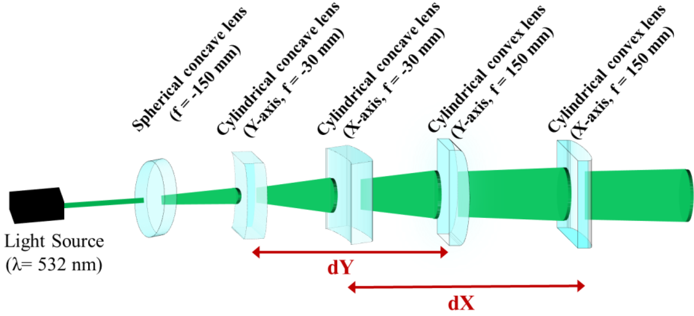
Figure 2 was designed as a two-axis independent beam shape control optical system for OWPT. A spherical plano-concave lens with a focal length of f = −150 mm was used to expand the beam emitted from the light source, and two pairs of lenses with focal lengths of f = −30 mm and 150 mm were arranged orthogonally to form a zoom optical system with plano-concave and plano-convex cylindrical lenses. In this experiment, a DPSS laser (LSR532H-1.5W, CivilLaser, Hangzhou, China) with λ = 532 nm was used as the light source to ensure visually visible conditions. This light source emits a single transverse mode, i.e., a Gaussian beam. The details of the light source specification are maximum output power of 1.85 W, beam size at aperture of 2.5 mm, divergence angle of 1.5 mrad, beam size at 4 m distance of 10 mm.
In this optical system, the divergence angle of the output beam can be controlled by independently adjusting the distances
dX and
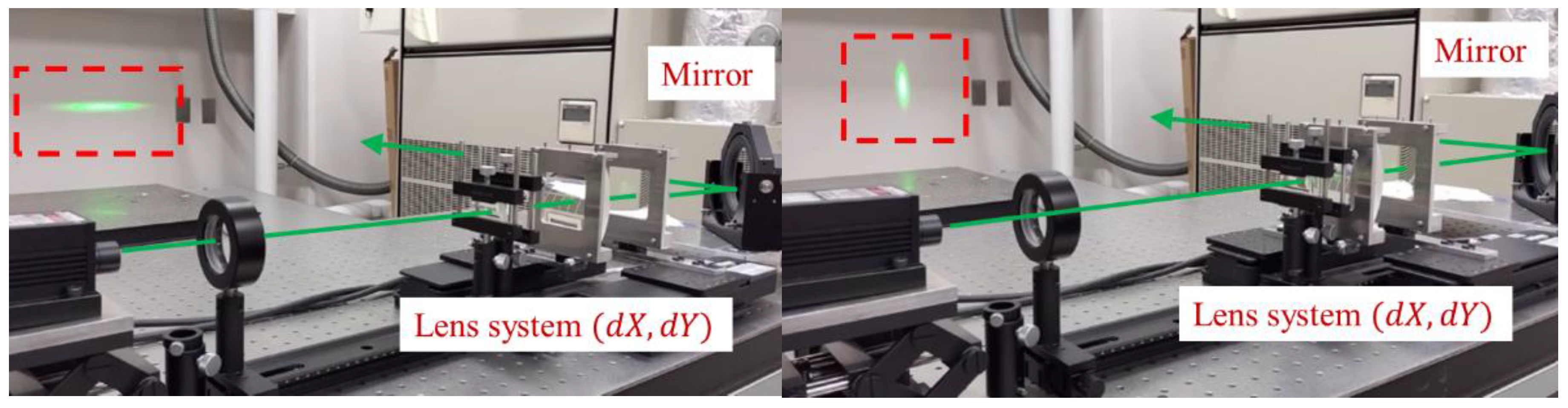
dY between the concave and convex cylindrical lenses in the x- and y-directions, respectively, allowing the beam shape irradiated to the receiver to be independently controlled along two axes. A photograph of the experimental setup is shown in
Figure 3. Due to the size constraints of the laboratory and the beam direction control discussed later, a mirror is used to manipulate the beam trajectory. With this experimental system, it was confirmed that, as an initial operation, the beam size could be controlled independently along two axes on a scale of several meters within the room.
3.3. Beam Shape Control System with Cylindrical Lens System
3.3.1. Numerical Control Model of Cylindrical Lens System
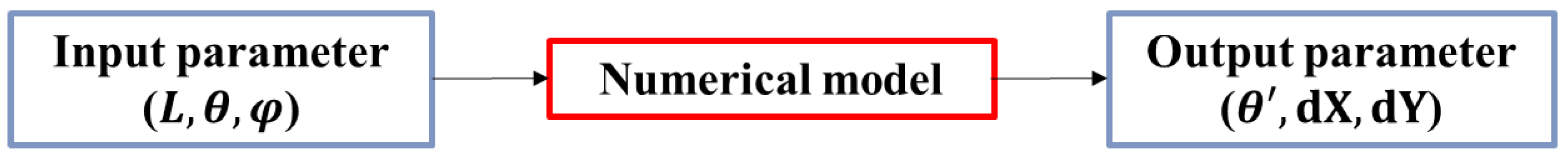
In the practical operation of the OWPT system, the beam shape changes depending on the position, attitude, and size of the receiver. A numerical model is essential to dynamically adjust the optical parameters based on the receiver data. In this section, a numerical model that provides feedforward control of the lens position for beam shape control has been constructed and evaluated.
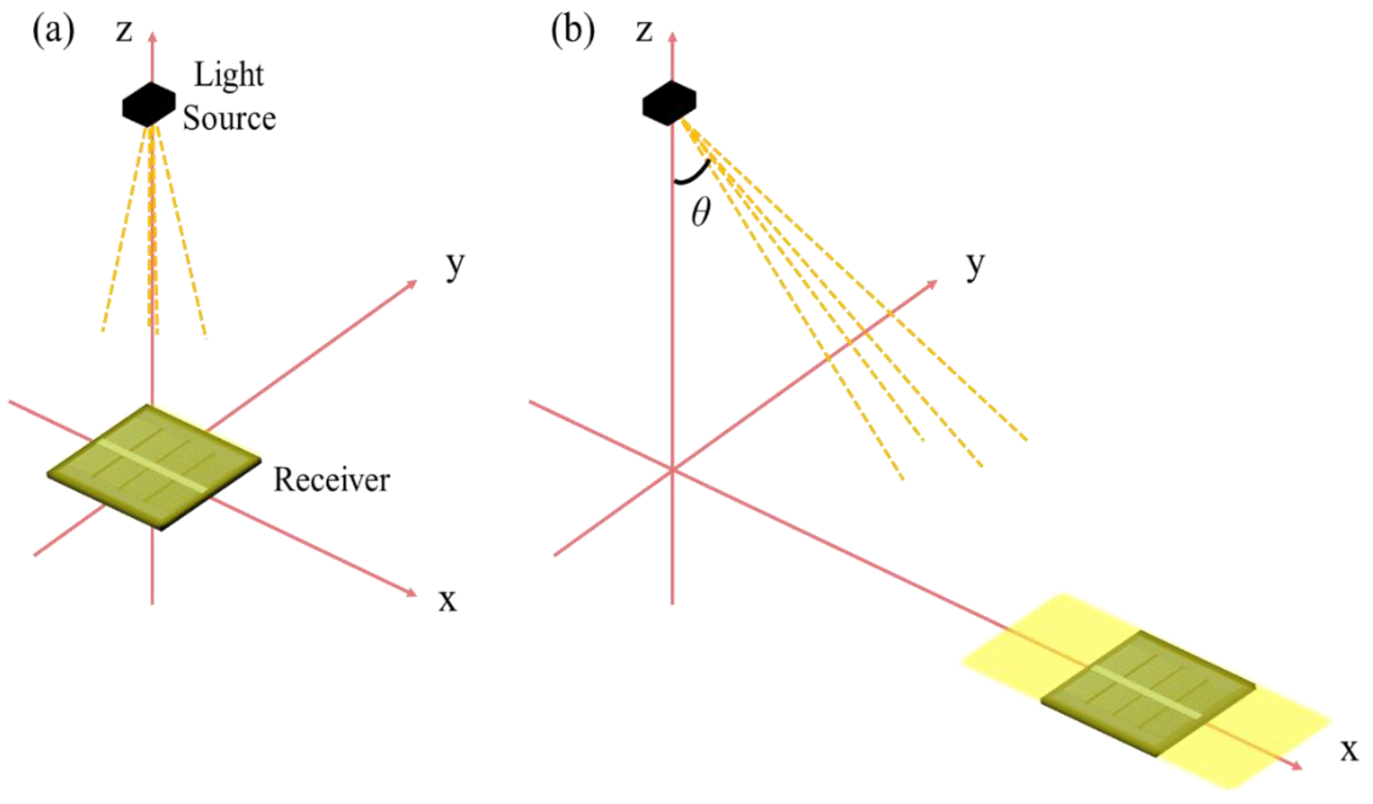
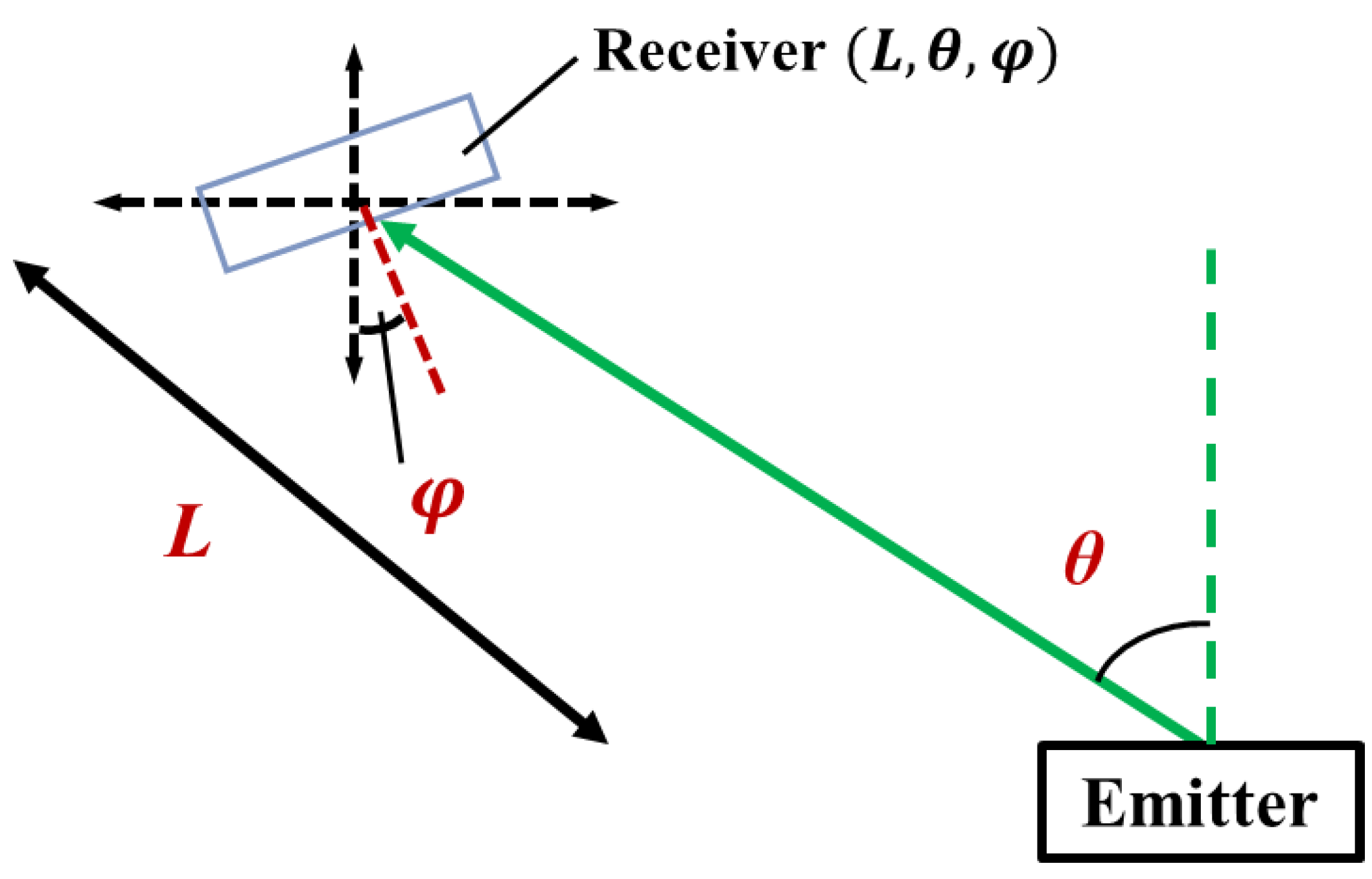
The positional relationship between the emitter and the receiver is assumed to be as shown in
Figure 4. When considering a moving object on a two-dimensional plane rather than just one-dimensional motion as in
Figure 1, the position of the moving object as seen from the light source can be expressed by the distance
and the azimuth angle
. The attitude of the receiver
is expressed by the attitude angle. It is important to note that oblique incidence situations can occur as a result of changes in receiver attitude. Therefore, the angle of beam incidence
, as expressed in Equation (2), uses the relative angle of the light beam as seen from the receiver.
The parameters of the receiver in the numerical model are the distance
, the azimuth angle
, and the attitude
. On the other hand, the parameters of the emitter
are the rotation angle for beam direction control and the lens positions
dX and
dY of the beam shape control optical system constructed in the previous section. In other words, a numerical model with the input–output relationship shown in
Figure 5 is required.
First, experimental verification was conducted using a feedforward control configuration to verify the operation of the beam shape control and evaluate its characteristics.
The beam diameter and beam divergence angle emitted from the lens system in
Figure 2 are calculated from the position of the device used and the focal length of the lens using a beam matrix. The beam radius and divergence in the x-axis and y-axis directions of the emitted beam in this system can be expressed as
using the beam matrix as in Equations (3) and (4). Here,
represent the beam radius and divergence in the x-axis and y-axis directions of the light source, and
represent the distance from the light source to the spherical lens and the distance from the spherical lens to the cylindrical concave lens.
and
are the lens matrices of the spherical lens and the concave and convex lenses, respectively. Note that the applied ray matrix is based on a paraxial approximation.
From Equations (3) and (4), the radius and divergence angle of the beam emitted from the lens system can be expressed in terms of
dX and
dY. When this beam is emitted from the emitter in
Figure 2, the parameters
dX and
dY of the lens system that realizes the corresponding beam shape can be expressed as Equations (5) and (6) by solving the beam matrix equation.
As a result, it is possible to obtain the lens system parameters required to irradiate a beam with an appropriate shape by using the parameters of the receiver on the detection side as input values.
3.3.2. Construction and Validation of Numerical Model
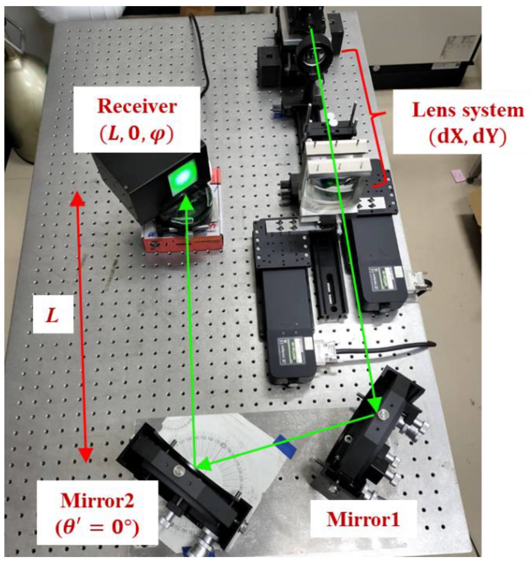
To facilitate the understanding of the characteristics of the numerical model in the optical system, an experimental system as shown in
Figure 6 has been constructed. The figure shows the propagation path of the beam emitted from the optical system constructed in the previous section, reflected by two mirrors, and then irradiated to the receiver. Mirror 1 is fixed, and the angle of mirror 2 is adjusted to direct the beam in the desired direction. In this system, the output parameter
is equal to the input parameter
in
Figure 5. The receiver in this experiment was a beam intensity profiler (LaseView-LHB, Kokyo, Kyoto, Japan). The maximum measurable size of the instrument is 5 cm square.
The light source in this experiment was a Gaussian beam. The beam shape was set to a circle with a diameter of 35 mm (1/e2 diameter). A numerical model was constructed to output the lens system parameters that would realize the desired shape of the light beam irradiation. The receiver parameters were used as input values.
In this experiment, the azimuth angle
was initially fixed at 0 degrees, but the distance
and the attitude
were varied. The lens position was manually adjusted to optimize the beam size to a diameter of 35 mm based on the beam profiler measurement results.
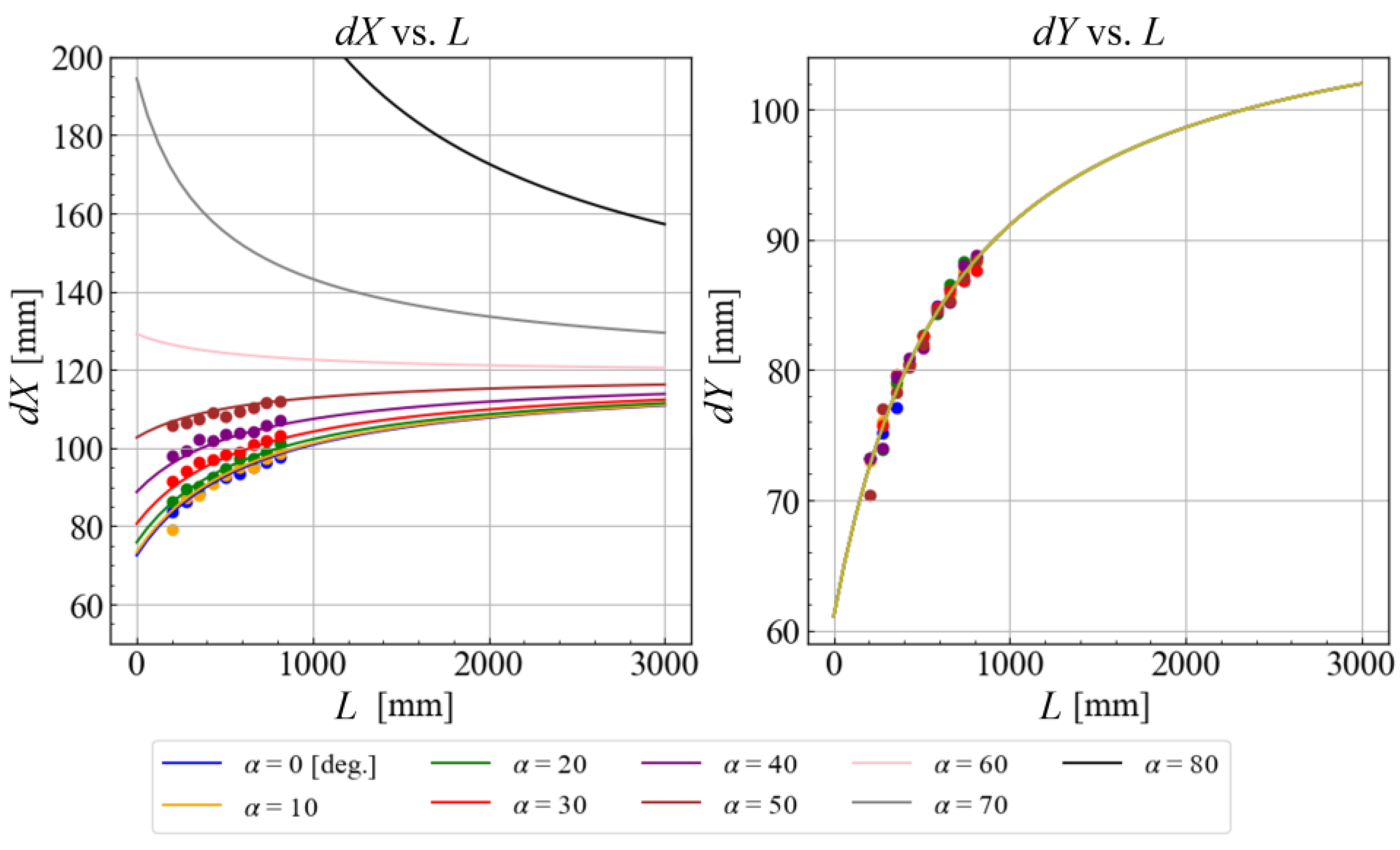
Figure 7 shows the values of
dX and
dY at each measurement point and the curves fitted by Equations (5) and (6).
From the experimental setup and motion conditions, it can be confirmed that
dX changes depending on the distance and incident angle, but
dY is determined only by the change in
, regardless of the incident angle
. The fitting curves for this experimental system are expressed by Equations (7) and (8).
The numerical values of these fitting equations are not significantly different from the theoretical values obtained from the ray matrix based on the specification parameters of the device used. However, by using them as experimental fitting parameters, it becomes possible to achieve more precise control in the experiment. Furthermore, by constructing this prepared numerical model, it became possible to adequately predict the
lens position to be controlled even at angles that could not be measured in the experimental system due to the limitations of the beam profiler measurement conditions. The calculation results for these angle ranges are also shown as curves in
Figure 7. Based on the above, Equations (7) and (8) were used as the numerical model for this optical system.
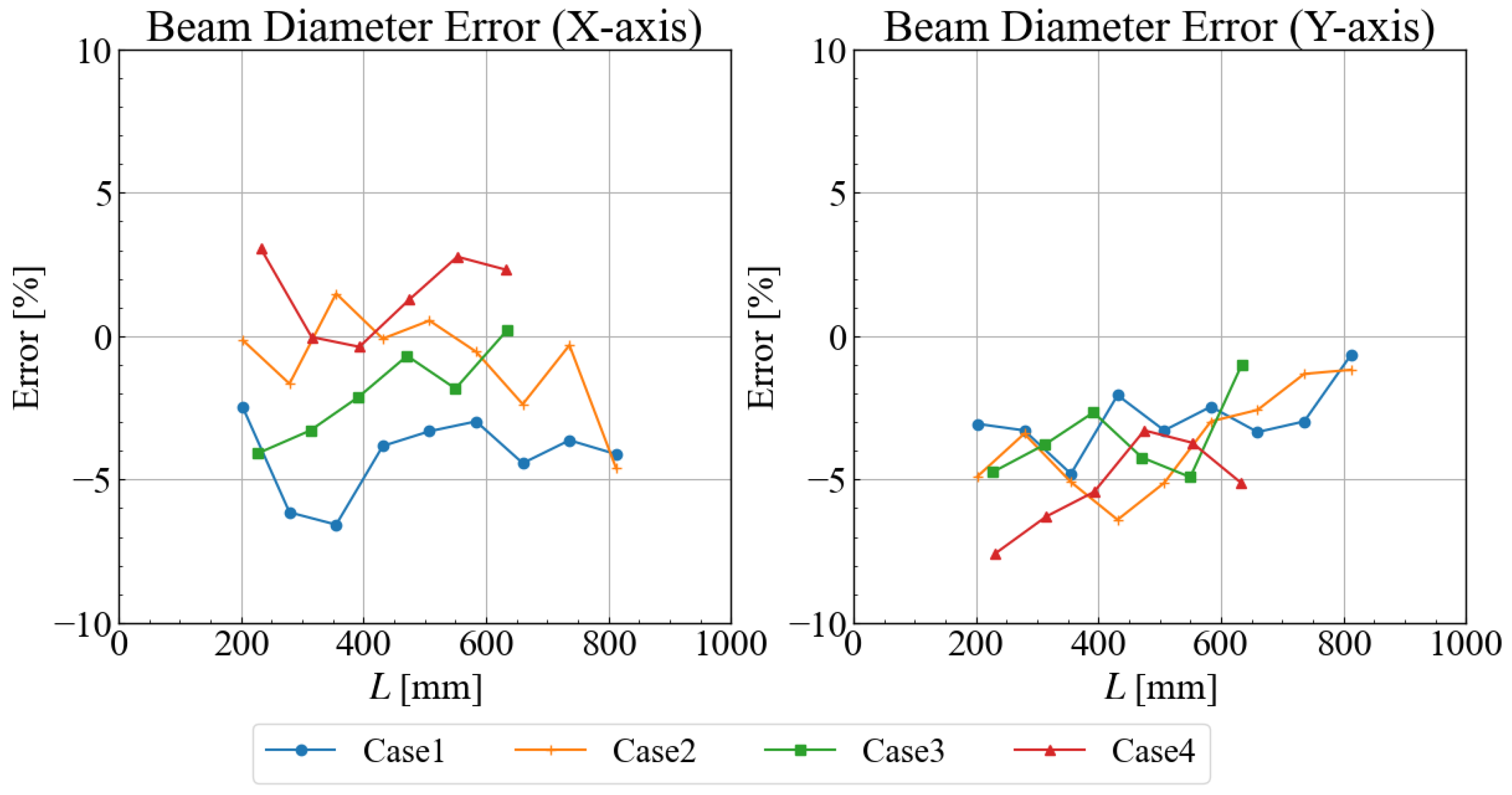
The controllability of the beam shape based on a constructed numerical model was experimentally evaluated. Under the four angular conditions shown in
Table 1, the beam size was measured by moving the receiving device (beam profiler) with the change of the irradiation distance L. In this experiment, the lens position was set according to the outputs of the numerical model so that the irradiation beam was at φ = 35 mm.
Figure 8 shows the results of the error between the measured beam size and the expected beam size along each axis. The horizontal axis represents the irradiation distance
, and the vertical axis represents the error ratio between the measured beam size and the size of 35 mm diameter size. The error was approximately ±8% at maximum, but was less than ±5% under most conditions. One of the factors contributing to the error is the presence of an error in the beam diameter and divergence angle of the light source used, with an error of about ±5%. However, the accuracy is sufficient for feedforward control of the beam shape. The error can be reduced to ± a few percent by more detailed evaluation of the beam characteristics and stabilization of the entire experimental system.
3.4. Beam Shape with VCSEL Array Light Source
In the previous section, a beam shape control system was constructed and evaluated using a Gaussian beam source in conjunction with a cylindrical lens system. These experiments were performed under the assumption that a solar cell would be prepared for irradiation with a Gaussian beam intensity distribution. This approach was adopted to take advantage of the stability and small divergence angle of the Gaussian beam source during long-distance propagation.
However, typical solar cells are configured with serially connected cells, which assumes a uniform intensity distribution. A fly-eye lens system has been proposed to be attached to the receiver to achieve a uniform intensity distribution of light on solar cells, even when using a light source with a non-uniform intensity distribution, such as a Gaussian beam [
23]. With a fly-eye lens system, as long as light is incident on its surface, it is possible to irradiate solar cells with uniform light within a certain range of conditions, with an allowable angle and tolerance for misalignment. However, for solar cells with a thickness of about 1 mm or less, a fly-eye lens system requires a thick light receiving module equal to the lens focal length of the lens, which limits its applications.
Therefore, when considering applications of OWPT with fewer constraints on the receiving side and greater flexibility, an optical system that can achieve uniform light beam irradiation on the transmitting side is important. In this section, a vertical cavity surface emitting laser (VCSEL) array light source [
29] was used, where each elemental VCSEL was arranged in two dimensions with a uniform light intensity distribution on the light source surface. Beam shaping control was applied to the VCSEL array. By controlling the beam shape according to the oblique incidence conditions, it is possible to irradiate a rectangular beam with effectively uniform intensity in the desired rectangular shape.
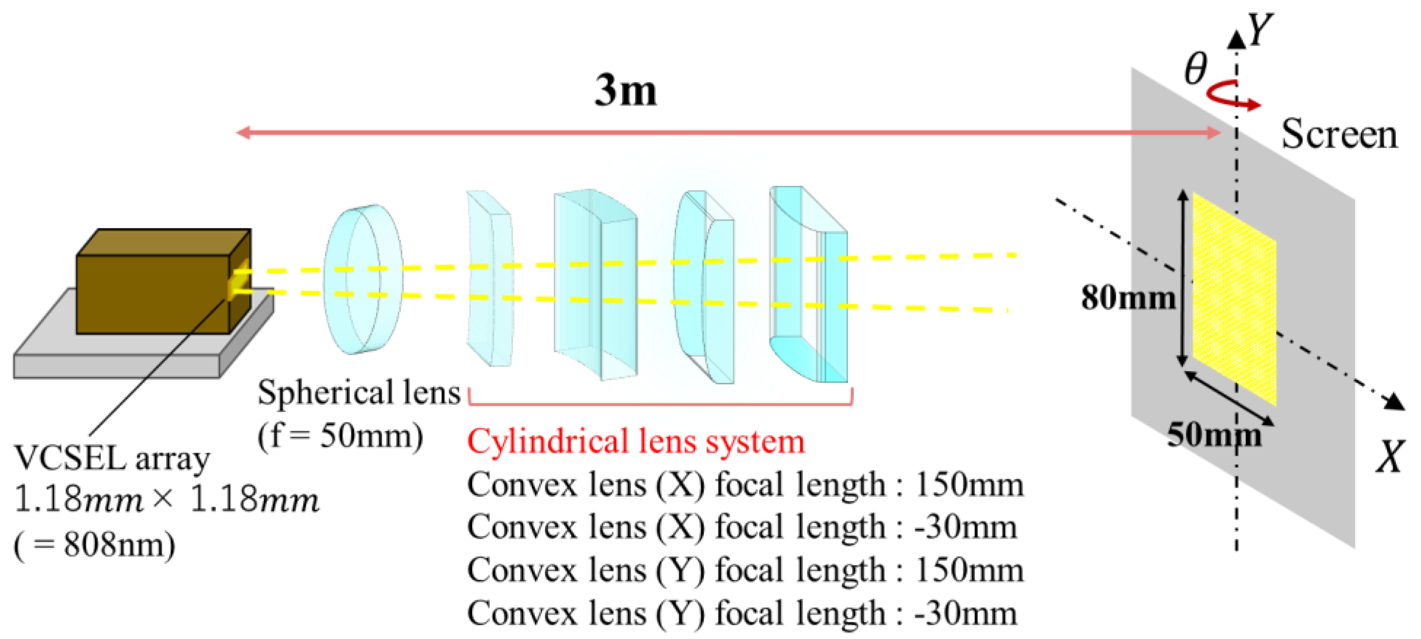
As in the previous section, a cylindrical lens system was used in an experiment to control the shape of the light beam to the size of a solar cell. The VCSEL array (PCW-C-2-W0808, Princeton Optronics, Trenton, NJ, US) used had a wavelength of 808 nm and a chip size of 1.18 mm square. The light source specifications include a maximum CW output power of 2.2 W, and conversion efficiency of 44%. In this experiment, a rectangular solar cell with a target size of 50 mm × 80 mm was assumed as the target. Due to the larger target size compared to the size of the light source, a plano-convex lens with a focal length of 50 mm was inserted between the cylindrical lens system and the light source, as shown in
Figure 9. By inserting a spherical lens, the beam divergence angle was suppressed and the distance to the screen was shortened, allowing the experiment to be performed at a laboratory size.
The screen onto which the light was projected was fixed at a position 3 m from the light source, and in order to create an oblique incidence condition, the positions of the four cylindrical lenses were manually adjusted to maintain a beam shape of 50 mm × 80 mm while changing the attitude angle
. In this case, the positions of the four lenses were adjusted independently as a zoom lens system, so the adjustment is more complicated than in the case of a Gaussian beam. The spherical lens was always fixed at a position of 55 mm from the light source.
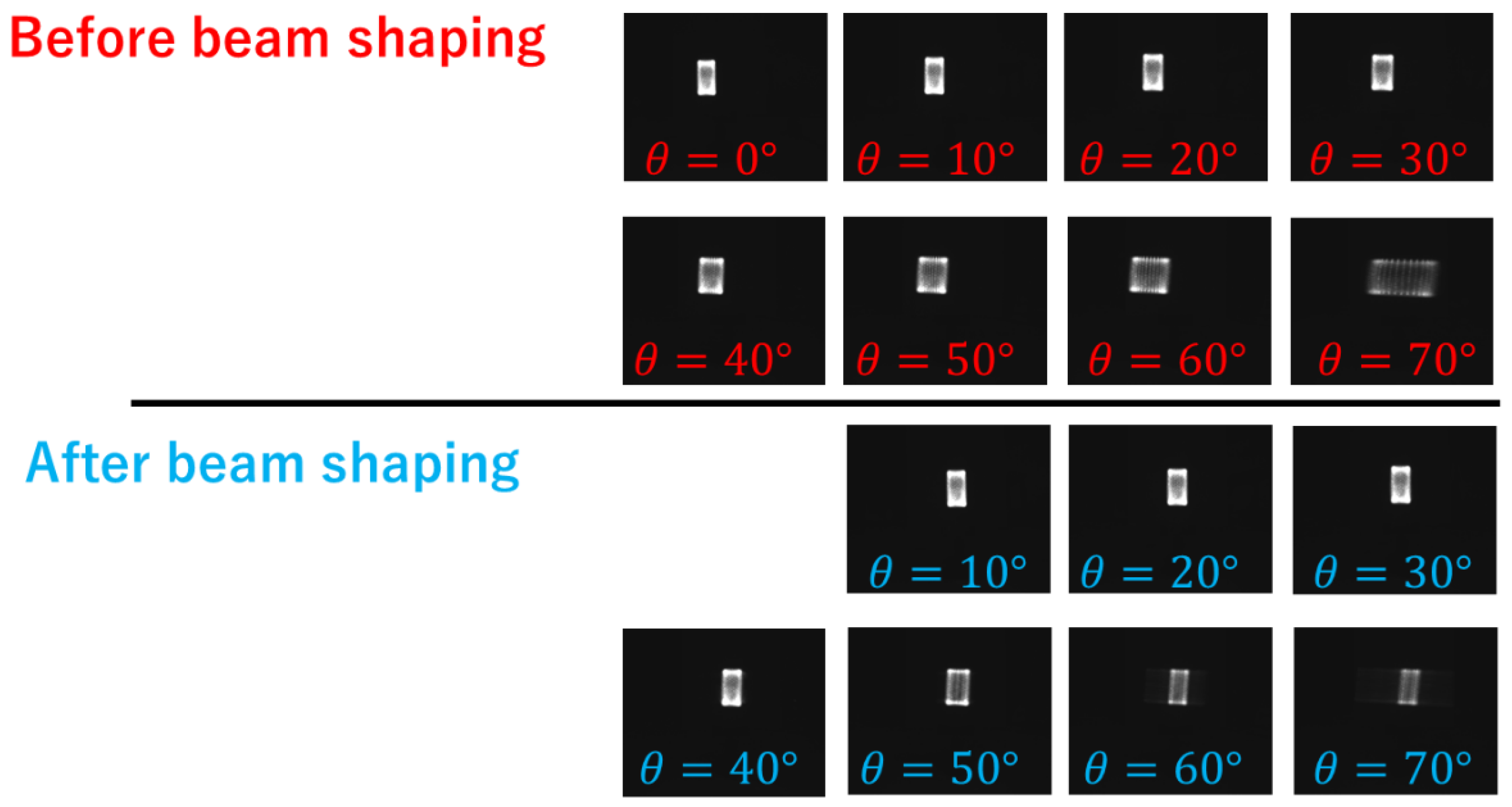
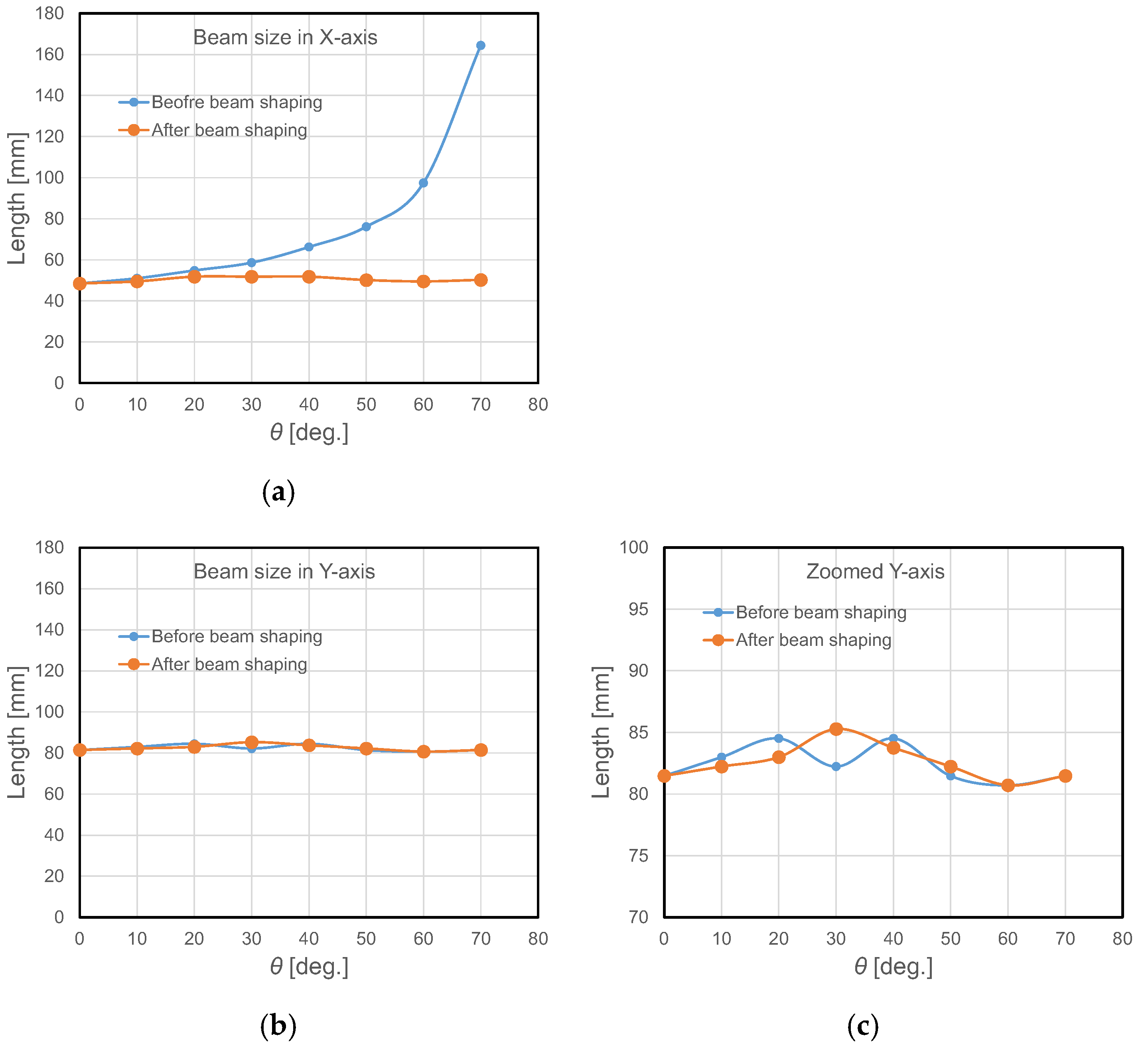
Figure 10 shows images of the light beam captured by the camera before and after changing the angle of attitude and controlling the beam shape.
Figure 11 also shows the graphs of the change in beam size.
These results confirm that while the beam size in the X direction increases with increasing angle θ, it can be controlled to 50 mm, the same as when θ = 0°, by adjusting the lens system.
From the above, it has been confirmed that a highly efficient OWPT system is possible by irradiating a beam of uniform intensity, even in a situation of oblique incidence, by controlling the beam shape using a VCSEL array light source and a cylindrical lens optical system, without the need for additional mechanisms or constraints on the receiving side.
4. Real-Time Beam Control System
A configuration approximating the practical operation of the OWPT has been verified. Feedforward control alone is insufficient due to device motion and observation errors, so feedback control is required. For this reason, accurate beam shape control requires feedback control such as that provided by a camera recognition system [
30]. It is also possible to use information such as the amount of power received by the receiving device for feedback.
In this section, a real-time beam control system has been constructed that uses the image detection technology of the receiver from the transmitter side and controls the shape of the light beam based on feedback control combined with the automatic control of the numerical model constructed in
Section 2.
The experimental system used the solar cell detection technology developed by the authors in previous studies [
31,
32] to detect images of the solar cells. It also constructed a real-time beam control system that integrates a beam shape control system with this solar cell detection method. This method uses two types of illumination light, one with a short wavelength and one with a long wavelength, both of which are close to the bandgap of the solar cell. It is noteworthy that the method can detect the solar cell with high sensitivity, as shown by the difference between the two capture images. In addition, a stereo camera method using two aligned cameras makes it possible to detect the position, orientation, and distance.
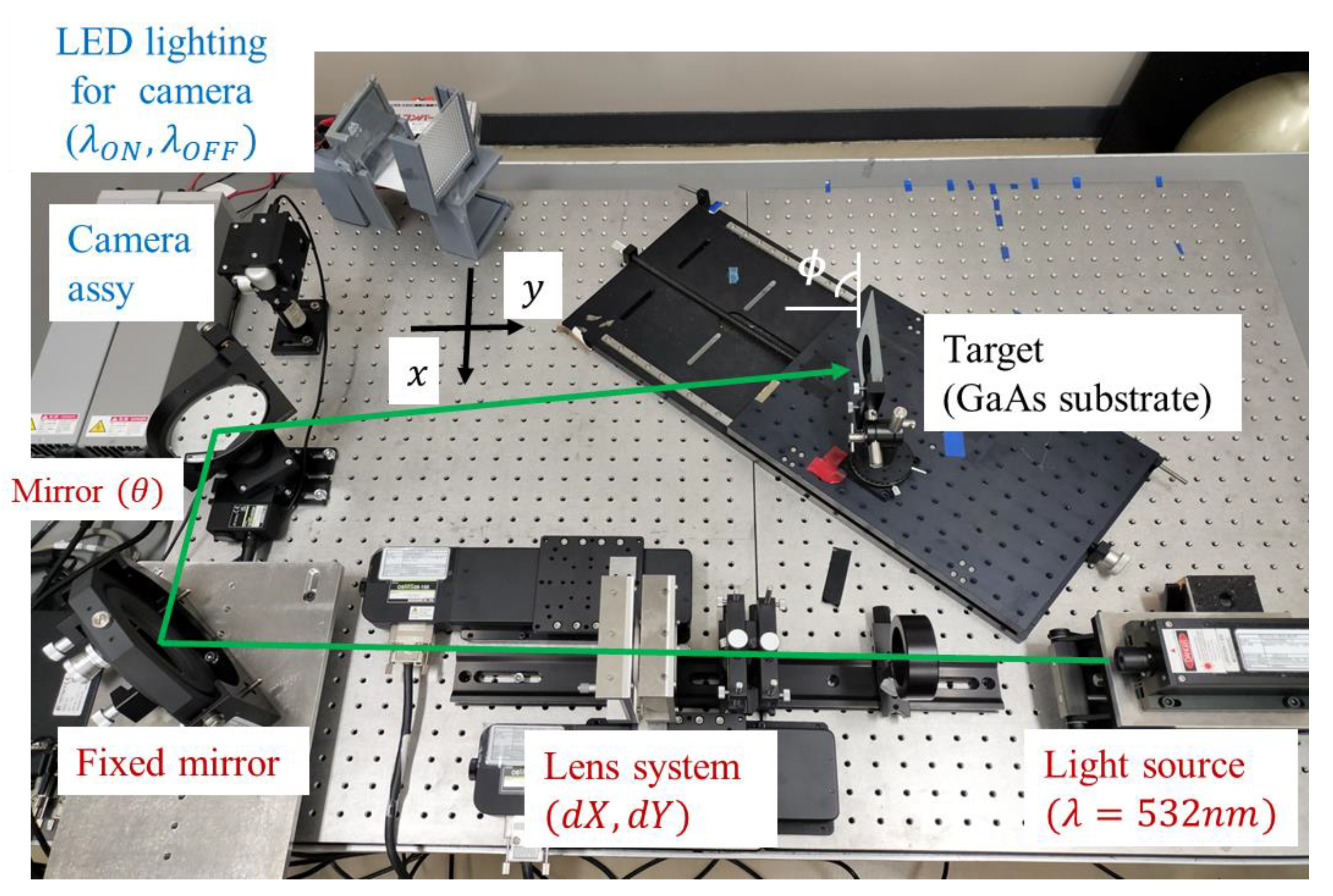
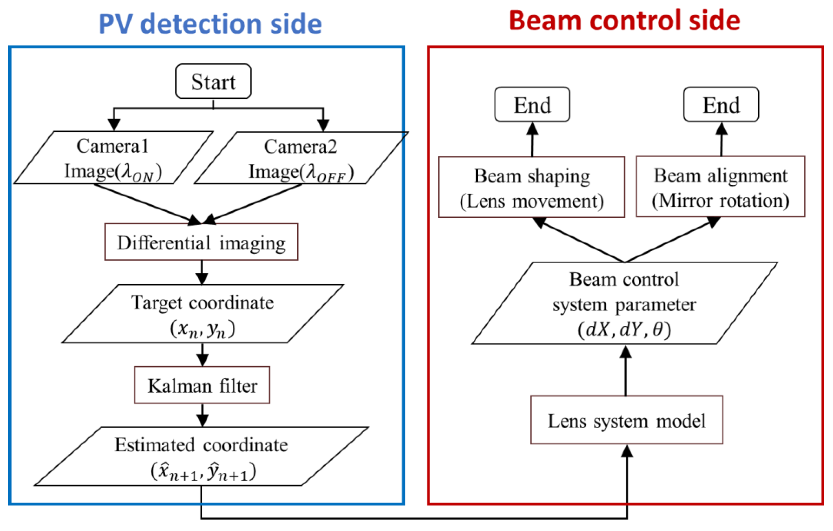
As shown in
Figure 12, the experimental setup consists of two primary mechanisms: a solar cell detection mechanism and a beam control mechanism. The system works as follows: the target coordinates obtained by the solar cell detection mechanism are used to automatically control the distance between the lenses and the rotation angle of the mirror in the beam control mechanism. This process enables the real-time irradiation of a light beam onto the moving target. It is important to note that, in this experiment, instead of actual solar cells, GaAs substrate, which is a component of a solar cell, was used as a detection target, and was mounted on diffusely reflective frosted glass. It has been confirmed that the detection of GaAs substrates, which have a scattering backside, can be performed with a higher degree of accuracy than the detection of commercially available solar cells, which have a flat backside [
32]. For these reasons, the GaAs substrate was used in this experiment to easily confirm the operation of the system. It was not possible to evaluate the actual amount of energy supplied by the OWPT system.
The solar cell detection mechanism is prepared on the left side of
Figure 12 and consists of an LED irradiation unit and two camera (Intel
® RealSense D435) modules. The LED irradiation unit irradiates the environment, including the target, with wavelengths that are absorbed by GaAs
(
) and wavelengths that are not absorbed
(
). A fly-eye lens is placed in front of the LED to diffuse the light emitted by the LED into the environment. This configuration is the same as that in Ref. [
32].
The beam control mechanism is shown at the bottom of
Figure 12. The light beam emitted from the Gaussian beam light source enters the lens system, where two sets of cylindrical lenses perform independent beam shaping control on two axes, and a light beam with an appropriate shape is irradiated onto the target by two mirrors, including a directional mirror. The convex cylindrical lenses in the X and Y directions are mounted on a motorized linear stage (OSMS26-100(X), SIGMAKOKI, Tokyo, Japan), and their positions are automatically controlled. The second mirror is also mounted on a motorized rotary stage (OSMS-60YAW, SIGMAKOKI), and the beam irradiation direction is also automatically controlled. The automatic control of the optical system was controlled from a PC using a Python (ver. 3.13.3) script.
The target is moved on a two-dimensional plane by moving stage, with the optical table (25.4 mm pitch screw holes) regarded as the x-y plane and the center of the fixed camera as the origin. This system can detect the moving target and form and irradiate a beam with an appropriate shape according to the target condition in real time. The target attitude angle is defined as positive counterclockwise, and 90° when directly facing the camera.
The operation flow of the system is shown in
Figure 13. The system continuously irradiates a properly shaped beam onto a moving target in the x-y plane in real time.
The detailed operation flow is explained below. First, the coordinates of the solar cell image are obtained using a differential imaging method. Then, the predicted target position coordinates are obtained with high accuracy, assuming a delay in the whole operating system, using a Kalman filter for noise removal and position estimation. In this system, a delay of 1 s is assumed, the main determinant of which is the solar cell detection mechanism. The position information is then sent to a numerical model of the lens system, which outputs the lens distances dX and dY of the cylindrical lenses in the beam control mechanism and the mirror rotation angle . The beam shape is then controlled by adjusting the lens position based on the values of dX and dY, and the beam alignment is performed by adjusting the mirror rotation angle based on the value of .
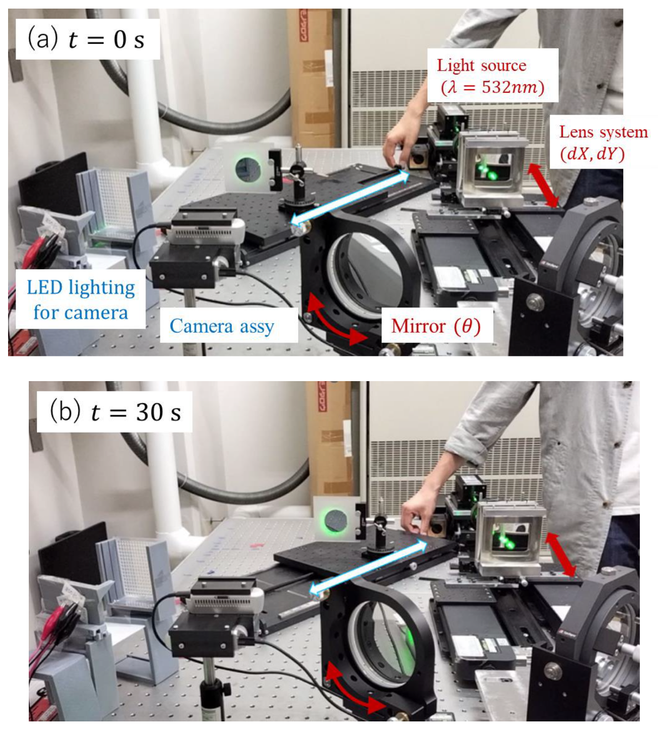
An experimental operational verification was carried out. The attitude angle of the target was fixed at 85°, and it was manually moved diagonally in a straight line on the x-y plane (on the optical table) from (−1, 18) to (4, 25) over a period of 30 s. The experimental conditions were such that the distance from the rotating mirror to the target was within 1 m. In addition, the target was set to be irradiated with a light beam of 50 mm (1/e2) in diameter, the same as the target size.
Figure 14 shows an actual demonstration, with the target moving linearly back and forth in the direction of the arrow in the figure.
Figure 14a shows the initial position of the target (t = 0 s), and
Figure 14b shows the state at the end of the motion (t = 30 s). In both figures, the GaAs substrate is irradiated with a green circular beam. It was visually confirmed that a beam of an appropriate shape was continuously irradiated onto the target in real time from the initial position to the end point.
To clarify the advantages of the proposed cylindrical lens-based beam shaping system, a comparison with other possible approaches is summarized in
Table 2. This includes not only conceptual differences, but also quantitative indicators in terms of applicable angles of incidence, light utilization efficiency, and system complexity. As shown, the proposed method achieves a significantly wider range of applicable angles and higher system flexibility, while maintaining high optical efficiency and eliminating constraints on the receiver side.


