Abstract
Offshore wind energy is increasingly considered a vital resource to contribute to the renewable energy future. This renewable energy can be converted to clean energy alternatives such as hydrogen and ammonia via power-to-x technologies, enabling storage, energy security, and decarbonization of hard-to-abate sectors. This study assesses the techno-economic feasibility of integrating offshore wind energy with hydrogen and ammonia production as sustainable energy carriers and their transportation via pipelines or shipping. The methodology incorporates Proton Exchange Membrane (PEM) electrolysis for hydrogen production, seawater desalination, and the Haber–Bosch process for ammonia production. Offshore transport scenarios are compared to evaluate their cost-effectiveness based on distance and electrolyzer capacity. Results show the levelized cost of hydrogen (LCOH2) ranges from EUR 6.7 to 9.8/kg (EUR 0.20–0.29/kWh), and the levelized cost of ammonia (LCOA) ranges from EUR 1.9 to 2.8/kg (EUR 0.37–0.55/kWh). Transportation costs vary significantly with distance and electrolyzer capacity, with levelized cost of transport (LCOT) between EUR 0.2 and 15/kg for pipelines and EUR 0.3 and 10.2/kg for shipping. Also, for distances up to 500 km, pipeline transport is the most cost-effective option for both hydrogen and ammonia. Despite high production costs, economies of scale and technological improvements can make offshore hydrogen and ammonia a promising means for a sustainable energy future.
1. Introduction
As the transition to net-zero emissions has increased interest in renewable energy generation, balancing real-time supply and demand remains challenging due to the intermittent nature and limited capacity factors of renewable energy sources (RES) [1]. One solution to this is the storage of renewable energy in chemical energy carriers [2], which can enable long-distance transport and deployment over extended periods and serve as a global reserve fuel [3,4]. Roughly 5% of the world’s electricity is produced by wind power, mostly by onshore wind installations. However, offshore wind farms benefit from higher wind speeds and consistency, resulting in greater energy production per turbine compared with onshore installations.
Hydrogen is the basis for most green chemical energy carriers with a higher energy density, i.e., 142 MJ per kg in liquid form compared with gasoline’s 46.5 MJ/kg [5], and potential for diverse applications. Hydrogen can play a vital role in achieving decarbonization goals, specifically in the chemical and petroleum industries, having an annual global demand of around 50 million tons [6] and establishing itself as the future clean energy carrier [7]. However, around 95% of hydrogen is being produced from fossil fuel processes such as steam methane reforming (SMR), liquefied petroleum gas (LPG), and refinery gas, resulting in an annual emission of around 900 Mt of carbon dioxide equivalent (CO2eq) [8]. Green hydrogen, produced through renewable energy-powered electrolysis, presents a cleaner alternative. Offshore power-to-hydrogen involves generating hydrogen using electricity from offshore wind farms, leveraging their relative advantages.
The European Commission aims to achieve a climate-neutral Europe [9] by installing a green hydrogen production capacity of over 40 GW by 2030, increasing the production up to 10 million tons annually. IRENA [10] estimates one-third of hydrogen production will be traded internationally by 2050, surpassing current natural gas trade levels.
Ammonia is a chemical derivative of hydrogen, with a liquid energy density of 21.2 MJ/kg [11] and a higher volumetric energy density of 3.83 MWh/m3 compared with 2.64 MWh/m3 for liquefied hydrogen [12]. Ammonia production needs only water, air, and power, i.e., the Haber–Bosch process, and emits no carbon upon combustion. Although roughly 80% of the annual production of ammonia is used in fertilizers, ammonia can serve as a direct energy carrier as a fuel in IC engines [13], gas turbines, and it can be converted back into hydrogen [14]. Ammonia production through the conventional fossil fuel-based Haber–Bosch process contributes nearly 2% of global CO2 emissions, making it the highest emitter in the industrial chemical processes. Hence, transitioning to green ammonia could significantly reduce emissions and support global decarbonization.
Using offshore wind power, with its higher capacity factors compared with onshore wind [15], for hydrogen and ammonia production presents a particularly attractive option. However, the higher cost of production, not competitive with fossil-based methods, is the key barrier to implementing an offshore wind-based green hydrogen and ammonia economy [16]. Currently, conventional fossil-based hydrogen, known as gray hydrogen, has a production cost of EUR 1–2/kg [17], and green hydrogen stands at EUR 7.28–12.68/kg [18]. The high cost of green hydrogen is largely attributed to the CAPEX of electrolyzers, around 50% of the total cost; electricity prices from RES, which are generally higher than natural gas used in the steam methane reforming process for gray hydrogen production; and lower electrolyzer efficiencies (60 to 70%) compared with SMR (75 to 85%). However, with economies of scale and government incentives like carbon certificates, green hydrogen is expected to be cost-competitive within a decade at under EUR 2/kg [19].
Offshore Wind Hydrogen Systems (OWHS) has gained substantial attention in renewable energy, with numerous research articles and pioneering demonstration projects worldwide. For instance, the Netherlands’ ‘posHYdon’ project integrates a 129 MW offshore wind farm with an electrolyzer, mixing green hydrogen with natural gas for delivery via a submarine pipeline [20]. BrintØ” (Hydrogen Island) [21] is expected to be able to supply an unprecedented amount of green hydrogen at around 1 million tons by 2030. The ‘NortH2’ project aims to be the largest OWHS with a 10 GW wind farm, transmitting wind electricity to shore for electrolysis on a gigawatt scale between 2030 and 2035 [22]. Germany’s ‘AquaVentus’ is another ambitious OWHS, aiming for 10 GW of wind power combined with electrolyzers and transporting hydrogen via submarine pipeline [23]. The UK’s ‘Dolphyn’ project aims to develop a GW-scale floating offshore wind farm in the North Sea by 2030. The project will include electrolyzers at sea to produce green hydrogen, which will be delivered via pipeline [24].
Although there are these ambitious large-scale projects in place, the offshore wind hydrogen industry is considered to be at the initial stage, with technical, economic, and environmental challenges [25]. The literature frequently features techno-economic analyses of OWHS in various scenarios and technologies, aiming to optimize the LCOH2 to compete with fossil fuel-based hydrogen production [26]. Dinh et al. [27] estimate costs for a hypothetical offshore wind farm and PEM electrolysis plant for 2030, recommending a minimum capacity of 100 MW for viable hydrogen production at EUR 5/kg hydrogen to be profitable, with underground storage for 2 to 45 days and electrolyzer operating hours between 60,000 and 110,000 h. Yan et al. [28] evaluated different scenarios of exporting hydrogen and power from offshore wind plants in Shanghai based on techno-economic performance, concluding that pipelines are the most cost-effective option for a baseline distance of 10 km with an LCOH of USD 3.40/kg. The study [29] highlights the potential of offshore liquefied hydrogen plants to decarbonize the naval sector. PEM electrolyzers with reverse osmosis for desalination and an 80–90% electrolyzer-to-wind farm capacity ratio were found to reduce payback time to 9–11 years at EUR 6/kg hydrogen. For wind farms over 150 MW, the LCOH2 was estimated to reach below EUR 4/kg.
Similarly, Zhao et al. [30] analyzed offshore wind-powered hydrogen transport via ammonia using pipelines and ships. LCOH2 was found to be USD 14.62/kg for pipelines and USD 15.54/kg for ships but dropped to USD 10.42/kg at 18,000 tons over 450 km, highlighting the need to optimize transport mass and distance. Cava et al. [31] analyze hydrogen truck transport using LOHCs (DBT/PDBT system), comparing it to compressed (350 bar) and liquefied hydrogen. Using ASPEN Plus simulations, they evaluate costs across hydrogen demands (1–4 t/day) and distances (50–300 km). Compressed hydrogen is found to be cheapest for short distances, while LOHCs are more cost-effective over longer ranges. Liquefied hydrogen requires fewer trips but is the most expensive. Environmentally, LOHCs and liquid hydrogen cut CO2 emissions significantly, highlighting LOHCs as a flexible, low-carbon transport option. Giampieri et al. [32] assessed offshore wind hydrogen production in the UK, finding compressed hydrogen as the most cost-effective (LCOH2 GBP 4.92–GBP 8.60/kg) by 2025, and ammonia and liquefied hydrogen more competitive (LCOH2 < GBP 2/kg) by 2050, driven by reduced electrolyzer costs. Long-distance transport (over 1000 km) favors shipping over pipelines, with cost-effectiveness influenced by shore distance and wind farm size. The paper [33] conducts a case study for offshore wind farms in the Iberian Peninsula and compares offshore wind-based hydrogen-carrying energy vectors (liquid hydrogen, ammonia, and compressed hydrogen) with all electricity production, identifying compressed hydrogen as the most cost-effective among the other options. It also highlights wind resource availability as the most critical factor for economic feasibility. Sage et al. [34] explore the potential of liquid organic hydrogen carriers (LOHCs) for hydrogen storage and export, particularly in the Australian renewable energy context. LOHCs offer advantages like safe, long-term, and loss-free hydrogen transport using existing fuel infrastructure. Compared with compressed or liquefied hydrogen, LOHCs are more cost-effective and safer for long-distance shipping. The paper discusses major LOHC candidates toluene, dibenzyltoluene (DBT), and N-ethylcarbazole (NEC), highlighting their transport readiness, energy demands, and dehydrogenation challenges. The study [35] evaluates hydrogen production at Portugal’s WindFloat Atlantic offshore wind farm, comparing current (25.2 MW) and future (150 MW) capacities. The 150 MW scenario was found viable at EUR 4.25/kg LCOH2 without subsidies, while the 25.2 MW scenario (EUR 8.47/kg) needs incentives, with oxygen sales to improve feasibility.
Jang et al. [36] evaluated green hydrogen production with offshore wind, comparing three configurations: distributed, centralized, and onshore production. The study identified distributed hydrogen production as the most cost-effective design, with LCOH2 ranging from USD 13.8 to USD 14.6/kg, highlighting the importance of maintaining capacity factors. The study [37] examines offshore green ammonia production using floating wind turbines, benefiting from better wind resources and reduced land use. Currently expensive, with floating turbines at USD 3 M/MW versus USD 2644/MW onshore, up to 33% of ammonia could be produced offshore in land-constrained scenarios, emphasizing offshore production where land limits and shipping benefits align, offering significant global potential.
Kim et al. [38] compare different scenarios for wind speeds, offshore distances, and electrolyzer types, identifying alkaline electrolyzers as having the most feasible prices for green hydrogen production, ranging from USD 1.64 to USD 4.46 per kg of hydrogen. Bai et al. [39] analyzed eight offshore wind–hydrogen–chemical routes, identifying offshore wind with PEM hydrogen blended with natural gas as the most cost-effective. Green ammonia production was achievable at USD 2.19/kg LCOH2, with the green hydrogen price as the key cost driver. The paper [40] evaluates green hydrogen production with offshore wind, identifying offshore electrolysis as the most cost-effective design at EUR 2.4/kg with hydrogen-driven operation. The paper identifies that the wind turbine and HVDC transmission costs heavily influence LCOH2.
Similarly, ref. [41] examines green ammonia production using offshore wind, finding it cost-effective, particularly with distant wind farms avoiding submarine cable costs. Floating turbines are needed for deeper waters, raising LCOA. By 2050, LCOA could drop 48–58%, making offshore ammonia competitive with land-based options. A case study in Singapore [42] revealed that importing blue hydrogen via pipelines at 70 bar pressure was the most cost-effective solution compared with trucks and ships for hydrogen and ammonia. A case study in Brazil [43] compared offshore and onshore hydrogen production scenarios for offshore wind, concluding that offshore production is more cost-effective and emphasizing further cost reduction potential by optimal sizing of the wind farm-electrolysis system.
Various studies indicate that ammonia can serve as a more cost-effective transport medium compared with direct hydrogen transport, particularly over long distances. The paper [44] explores China’s potential to supply green hydrogen to Japan using offshore wind. It found methylcyclohexane (MCH) as the cheapest transport option, followed by ammonia, with liquid hydrogen being the priciest. Elvira et al. [45] compare liquefied hydrogen (LH2), ammonia (NH3), and LOHCs (toluene, dibenzyl toluene) for harbor-to-harbor hydrogen transport over 2500–10,000 km, assessing costs for industrial and mobility uses. NH3 is found to be the most cost-effective for industry, while LH2 suits mobility due to easier pressurization. LOHCs are competitive at shorter distances but are limited by high dehydrogenation and initial loading costs. The study highlights the need for process improvements in liquefaction, NH3 synthesis, and LOHC dehydrogenation to enhance future viability. Similarly, ref. [46] analyzes ammonia as a hydrogen carrier from offshore wind energy to Wales, finding the most cost-effective scenario involves ammonia transport from Orkney to Milford Haven, with an LCOH2 of USD 9.93/kg, which is USD 0.93–USD 2.53/kg cheaper than direct hydrogen transport. Pipeline transport follows at USD 11.23/kg. Peecock et al. [47] present a techno-economic comparison of three hydrogen transport vectors—liquefied hydrogen (LH2), ammonia (NH3), and a liquid organic hydrogen carrier (LOHC, specifically dibenzyl toluene)—for marine shipping between Canada and the Netherlands. It evaluates costs, energy efficiency, and system losses across the full transport cycle, revealing that LH2 and NH3 are more cost-competitive (USD 6.35–6.75/kgH2) and efficient (66.6–71.9%) than LOHCs (USD 9.49/kgH2, 55.6%). While LOHCs offer advantages like easier handling and stability, their high conversion energy needs and material costs reduce viability unless integrated with waste heat recovery systems.
Most studies have primarily focused on the production costs of green hydrogen and ammonia, with limited attention on the transportation costs associated with offshore wind farms, particularly for analyzing the trade-offs between pipeline and shipping options for different electrolyzer capacities and distances. This study aims to fill this literature gap by considering different solutions for transport, i.e., pipeline and ship transportation, to provide a complete view of the economic viability of such integrated systems. The novelty of this research lies in the integration of offshore wind power with hydrogen (OWP2H) and ammonia (OWP2A) production and transportation for varying electrolyzer capacities and distances. Particularly, we conduct a comprehensive analysis by calculating the final levelized cost of hydrogen (FLCOH2) and ammonia (FLCOA), considering the cost of production, expressed in terms of levelized cost of hydrogen (LCOH2) and levelized cost of ammonia (LCOA), and cost of transport, expressed as LCOT. By examining these costs, we aim to identify the most efficient and cost-effective strategies for large-scale implementation of offshore wind-powered hydrogen and ammonia production and transportation for different sizes and distances to propose the optimal solution for each particular case.
2. Methodology
In this section the methodology is shown, and both technical and economic assumptions and equations are discussed in detail.
The system has been thought to be centralized; thus, electricity produced by the individual turbines is conveyed through electric inter-array cables to the substation where a Proton Exchange Membrane (PEM) electrolyzer is installed. Additional systems such as the air separation unit (ASU), Haber–Bosch (HB) loop, and storage are considered to transform green hydrogen into green ammonia and are also installed on the same platform as the electrolyzer. To justify the methodological assumptions, we note that PEM electrolysis is selected due to its rapid response characteristics and maturity in dynamic offshore environments [48]. The economic analysis is conducted in this article by calculating LCOH2 and LCOA for offshore wind power, and LCOT is calculated for two transportation scenarios, i.e., pipelines and shipping. All information about devices and the assumed data are described in the methodology section and the Supplementary Material, when specific technology have been selected the manufacturer information are also mentioned.
2.1. Levelized Cost of Hydrogen
LCOH2 (EUR/kg) represents the average cost of hydrogen production over a project’s lifespan, calculated by dividing total lifetime costs (CAPEX, OPEX, and DECEX) by total hydrogen production (in kilograms). It is a key parameter to evaluate the economic viability of hydrogen production from offshore wind farms. LCOH2 calculation also takes into account the discount rate over the project lifespan (in years), as illustrated in Equation (1).
CAPEX includes the wind turbines and their floating foundations, offshore platforms housing the electrolyzer and related equipment, the electrolyzer itself, the desalinator, the compressor, and electric inter-array cables. It also accounts for the installation costs (IC) and logistic costs of offshore platforms. A project discount rate of 8% and a 30-year operational lifetime are assumed, following common industry practice [49]. For detailed analysis, refer to Supplementary Materials. OPEX, on the other hand, encompasses operational and maintenance expenses.
Table 1 shows OPEX as a share of CAPEX. The decommissioning operations are very similar to the installation processes, but the dismantling times are significantly lower. The DECEX cost is taken from 50% of the installation [50].

Table 1.
OPEX as a share of CAPEX costs, sources [40,51].
2.2. Hydrogen Transportation
2.2.1. Transportation by Pipeline
The levelized cost of transport of hydrogen (LCOTH), a key parameter, is used to assess the economic viability of transporting offshore-produced hydrogen to onshore facilities. Both capital expenditure (CAPEX) for constructing transmission infrastructure such as pipelines or shipping vessels and the operational expenditure (OPEX) for its maintenance and operation throughout its lifespan are considered for LCOTH. For pipeline (LCOTH_Pipeline), refer to Equation (2) [49].
The CAPEX covers material and installation costs. OPEX accounts for operational costs (2% of CAPEX) [49], drate is the discount rate (taken as 8%), and the L represents project lifetime (taken as 30 years) [49]. ProdH2 is annual hydrogen production, calculated by dividing the annual energy production of the wind farm by the effective energy consumption (kWh per kg H2) of the electrolyzer, and l represents each year in the timeline. Note that the electrolyzer capacity (Ecap) is sized the same as the power output of the wind farm. This is performed because the wind farm is not connected to the main grid; thus, the optimal economic solution is to exploit all the electricity production by producing hydrogen/ammonia. Indeed, by reducing the electrolyzer size, we would not be able to valorize part of the electricity produced by the wind farm, thus negatively affecting the system economy.
For capex, assumptions are made to simplify calculations. Natural gas pipeline construction costs are evaluated and then adapted for hydrogen pipelines. A multiplier factor of two for offshore pipeline costs compared with onshore ones reflects added complexity from subsea installations, as supported by [52].
Referring to [49], the costs for piping and compressors needed to offset pipeline pressure losses are considered. Unlike natural gas, hydrogen pipelines operate at higher pressures, requiring thicker-diameter pipelines. The mass flow rate of hydrogen can be calculated using Equation (3).
Considering the use of austenitic steel and high piping costs for the hydrogen pipeline at 100 bar pressure, as reported in [49], the polynomial equation for transmission line CAPEX () in EUR/km for the hydrogen transportation pipeline is given in Equation (4).
For the offshore case, Equation (4) is multiplied by a factor of two [52], Equation (5).
The diameter (D) can be inserted from Equation (3) into the CAPEX equation. The CAPPIPELINE can also be presented as a function of electrolyzer capacity (Ecap), Equation (6), rather than as a function of the pipeline diameter. This will facilitate the visualization and comparison of pipelines and LH2 tankers as they will be calculated for several electrolyzer capacities and distances.
The production rate of hydrogen (Prate), based on the Siemens SILYZER 300 PEM electrolyzer, by Siemens Energy AG, Munich, Bavaria, Germany, is taken from [53] and is equal to 0.0055 kgH2/s/MW. The CAPPIPELINE as a function of the electrolyzer’s capacity is given in Equation (7).
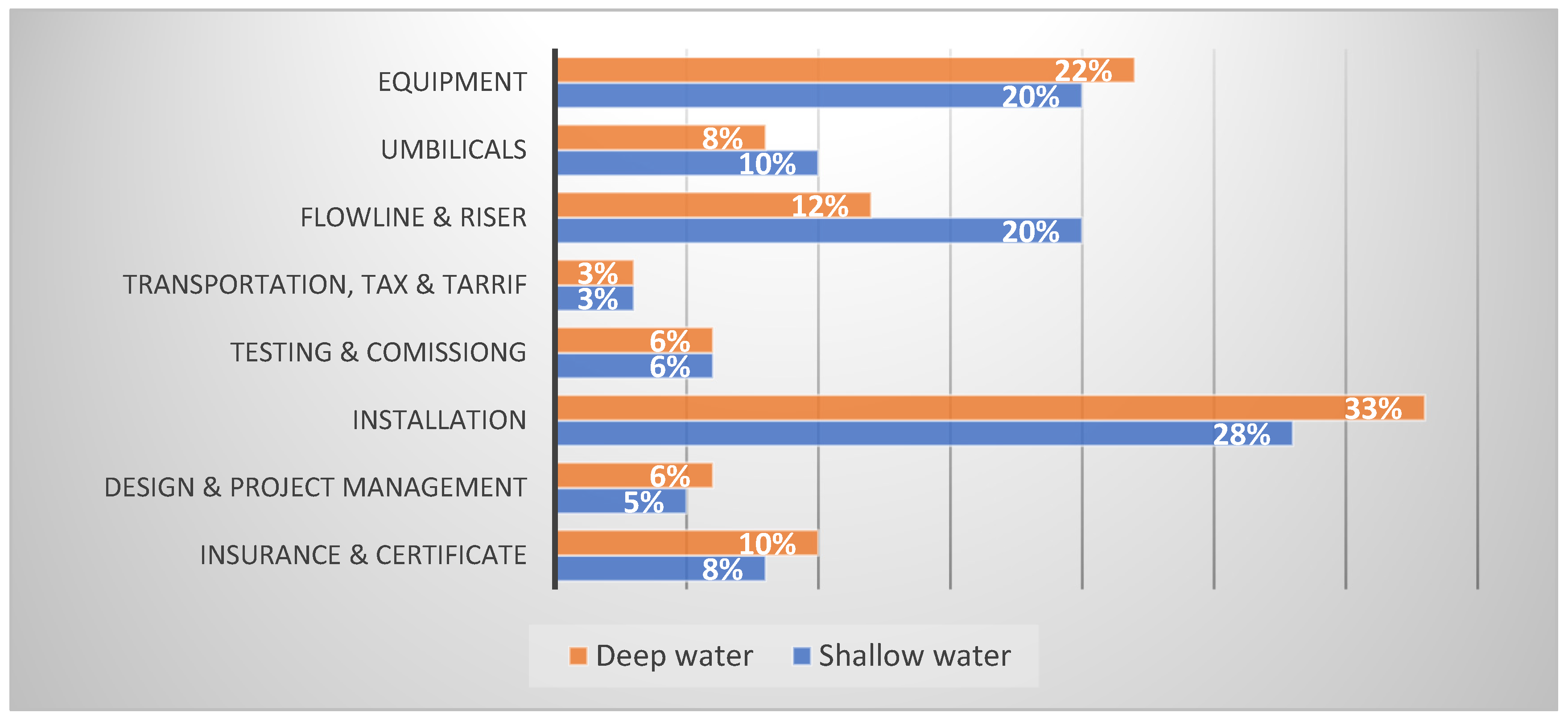
The hydrogen density of 8 kg/m3 is taken at 100 bar and 20 °C, and V is the hydrogen flow velocity in the pipeline (15 m/s). Compressors (every 250 km) are considered, excluding engineering, planning, and consenting costs. Offshore pipeline construction costs depend on ship travel, installation time, and job duration, with installation accounting for 28–33% of CAPEX (CAPPIPELINE), varying by water depth [3,54], as illustrated in Figure 1.

Figure 1.
Shallow- and deep-water subsea CAPEX breakdown.
2.2.2. Transportation by Ship
Currently, the SUISO Frontier, developed in Japan as a demonstration project [55], is the only liquid hydrogen tanker in operation. The schematic for transporting liquefied hydrogen (LH2) in tankers by ship is shown in Figure 2.
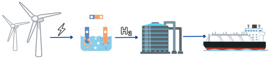
Figure 2.
Offshore hydrogen transportation through ships.
The CAPEX for LH2 tankers is given by Equation (8) and is composed of three main elements: liquefaction cost (CAPEXliq), storage cost (CAPEXsto), and ship cost (CAPEXship). Only liquid hydrogen (LH2) is considered for ship transport [49].
The CAPEXliq (in EUR) is based on [56], shown in Equation (9),
The storage capacity of the LH2 tanker, as described by Equation (10), includes factors such as tanker capacity (Tcap), transmission distance (d), number of vessels (nship), vessel speed (Vship), and electrolyzer production rate (Prate). The equation assumes zero storage unloading time, with storage capacity denoted as Scap. The is given in Equation (11) considering a unitary cost per kilograms of stored hydrogen (Pricesto) expressed in €/kgH2.
As LH2 tankers share technical similarities with LNG tankers, the price of a new vessel (CAPEXship) can be estimated using Equation (12) [49], based on the benchmark vessel’s price (PriceB), the new vessel’s capacity (CapA), and the benchmark vessel’s capacity (CapB), assuming the price-capacity relationship for LNG tankers applies to LH2 tankers since only one LH2 tanker has been constructed [55], and its cost data are not publicly accessible. The benchmark LH2 tanker data are given in Supplementary Materials (Table S6).
Shipbuilding costs were based on capacity, and charter costs were estimated using the internal rate of return (IRR) method [57], set at 10%. Freight prices in Equation (13) were adjusted until the Net Present Value (NPV) of cash flows reached zero. OPEXship was calculated as a percentage of CAPEXship in EUR, while Chartercost represented annual freight costs in EUR. The lifetime (L) began at year 5 to include the design and construction period. LH2 tanker assumptions and parameters used are given in the Supplementary Materials (Table S6).
The LCOT for LH2 tankers is given by Equation (14):
The OPEX for transporting liquefied hydrogen (LH2) by tanker is given in (15) [49]. It includes OPEXliq for liquefaction, OPEXsto for storage (boil-off losses and cryogenic maintenance), OPEXship for the crew, maintenance, insurance, and onboard systems, and Chartercost for leasing or operating the tanker.
Hydrogen boil-off loss during storage (Boffsto) is calculated using Equation (16), and during shipping (Boffship), Equation (17):
2.3. Levelized Cost of Ammonia
Green hydrogen can be converted into green ammonia. Ammonia synthesis follows the well-established Haber–Bosch process [58] by a reversible exothermic reaction, as shown in Equation (18). Ammonia storage uses mature technologies: pressurized cylinders (up to 270 tons at 20 °C, 10 bar) or refrigerated tanks (up to 50,000 tons at −33 °C, 1 bar), both widely adopted globally [59].
The energy consumption of the Haber–Bosch process is considered to be negligible compared with the hydrogen production being in the range of 0.7–0.8 kWh/kgNH3 [56]. The LCOA (EUR/kg) is used to evaluate the economic viability of ammonia production using offshore hydrogen. It is calculated in Equation (19).
where CAPEX represents the capital expenditures (Supplementary Materials), OPEX represents the operational expenditures, DECEX represents the decommissioning costs, ProdNH3 refers to the amount of ammonia produced per year, and ‘L’ is the project’s lifetime; for details, refer to [60]. Ammonia production is given by Equation (20).
2.3.1. Ammonia Transportation by Pipeline
Ammonia is commonly transported through carbon steel pipelines with diameters ranging from 0.15 to 0.25 m in its liquid state at pressures of approximately 17 bar. Referring to [49], Equation (21) is used to obtain the diameter of the pipe in centimeters,
where Pipecapacity is the capacity of the pipeline carrying ammonia in tons/year. Referring to [49], for optimal distancing at 128 km, the total number of pump stations can be found for the total pipeline length.
The pipeline cost () is calculated from Equation (22):
where the (cost per unit length for a 25 cm diameter pipeline) is set to 0.771 MEUR/km [49]. Subsea pipelines require stricter standards in terms of anti-corrosion measures and structural stability. As a result, the cost of offshore pipelines is assumed to be double that of their onshore counterparts [39], Equation (23). The OPEX for the pipeline is taken at 2% of the CAPEXpipe [49].
2.3.2. Ammonia Transportation by Ship
Ammonia is typically transported using gas carriers originally designed for liquefied petroleum gas (LPG) [61]. The total cost for ammonia tankers (CAPEXtanker) is expressed as the sum of ship costs (CAPEXship) and storage costs (CAPEXstorage), as shown in Equation (24) [49].
The CAPEXship is calculated by multiplying the unit cost of a ship (Cship), 76.5 million euros [49], by the number of ships required. Similarly, storage costs (CAPEXstorage) are obtained by multiplying the unit cost of a tank (Ctank), 61.2 million euros for a 34,100 tNH3 capacity [49], by the number of tanks required. The ship can take two tankers at a time.
The number of ships (nship) is determined by ammonia production, ship capacity, and transportation time.
Referring to [49], the total OPEX for tankers is defined in Equation (25).
The cost of fuel () is evaluated to be 172 EUR/km [62]. The levelized cost of transportation (LCOTNH3 tanker/pipeline) for ammonia tankers and pipelines is given by Equation (26).
2.4. Sensitivity Analysis
In this section, we present the sensitivity analysis conducted to assess the impacts of varying key parameters on the total levelized costs of hydrogen after transport both via pipeline and shipping. The sensitivity analysis varied each of the parameters individually while maintaining all others with the standard values to identify their specific impact on the overall results. The parameters under study included the following:
- Capacity Factor (CF) of the wind farm: Analyzed at values of 30%, 40%, and 50%.
- Efficiency of the PEM electrolyzer: Considered at 50%, 60%, and 70% [63].
- CAPEX variations for turbines and platforms: Evaluated at −20%, baseline (100%), and +20%.
- CAPEX variations for electrolyzer and its platform: Similarly assessed at −20%, baseline (100%), and +20%.
The analyzed parameters and sensitivity scenarios are summarized in Table 2.
Table 2.
Parameters for sensitivity analysis.
3. Results and Discussion
3.1. Levelized Cost of Hydrogen/Ammonia
The first result that needs to be discussed is the relationship between the LCOH2 (in blue) and LCOA (in red) with electrolyzer capacity, as shown in Figure 3.
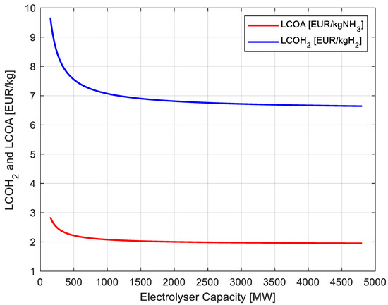
Figure 3.
Levelized cost of hydrogen/ammonia [EUR/kg] vs. electrolyzer capacity [MW].
It can be observed that LCOH2 and LCOA decrease with increasing electrolyzer capacity as expected per economies of scale. The LCOH2 is higher than ammonia in terms of mass (per kg) and it is thus useful to understand the cost of hydrogen and ammonia as feedstocks. Nevertheless, if ammonia and hydrogen production objective is for energy uses, a fair comparison would be the converted values in EUR/kWh, considering their primary energy content. To use ammonia for electricity production, it can alternatively be reconverted to hydrogen to use in fuel cells. Figure 4 presents the converted values in EUR/kWh, the values are converted from EUR/kg to EUR/kWh by dividing by their respective lower heating values (LHV) i.e., 33.33 kWh/kg for hydrogen, and 5.17 kWh/kg for ammonia.
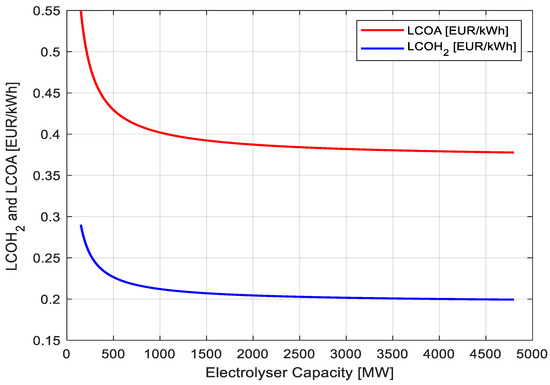
Figure 4.
Levelized cost of hydrogen/ammonia [EUR/kWh] vs. electrolyzer capacity [MW].
Here, ammonia, which was observed to be cheaper than hydrogen per unit mass in Figure 3, appears more expensive per unit of energy in Figure 4. This is because ammonia has a lower LHV than hydrogen and thus a lower energy density, meaning that even though ammonia needs a lower cost to produce per kilogram, its energy content is significantly lower. This highlights a fundamental perspective in choosing hydrogen or ammonia as an energy carrier.
3.2. Levelized Cost of Transport for Hydrogen and Ammonia
3.2.1. Hydrogen
The results for LCOT for hydrogen highlight the impact of electrolyzer capacity and transmission distance, emphasizing their critical role in determining the optimal offshore hydrogen transmission technology. The analysis considers a wide range of transmission distances, from short (10 km) to long-range scenarios (up to 3000 km), in order to capture the spatial variability typical of offshore applications and energy vectors (i.e., hydrogen and ammonia) transport and trade that is often intercontinental. Similarly, electrolyzer capacities are varied from 100 MW to 5000 MW to assess the influence of system scale on transmission cost metrics. This dual-parameter evaluation enables a comprehensive investigation of how both distance and plant size affect the economic performance of offshore hydrogen transport infrastructures.
To better understand how transmission distance and electrolyzer capacity influence the offshore hydrogen transport cost, Figure 5 presents a three-dimensional plot illustrating the CAPEX associated with offshore hydrogen pipelines.
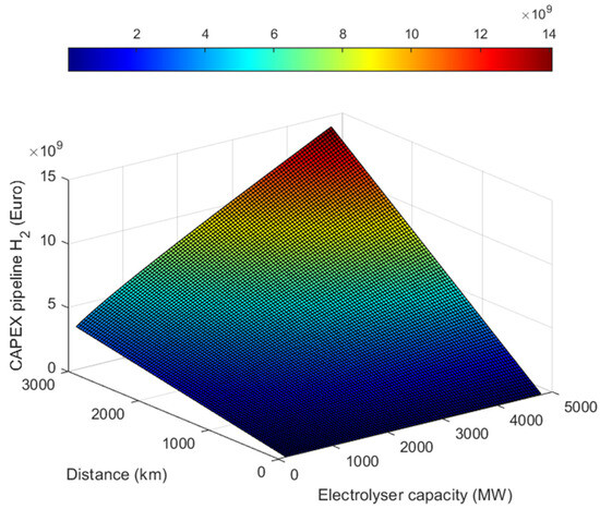
Figure 5.
CAPEX pipeline vs. electrolyzer capacity and distance to shore for hydrogen production and trasnportation.
It can be observed that the CAPEX of pipelines increases substantially with greater distances and larger electrolyzer capacities. This is due to the material and installation costs that increase with the physical size of the pipeline and the volume of hydrogen transported. For shorter distances, up to 500 km, the CAPEX remains relatively modest, even for high electrolyzer capacities. However, as distances extend to 3000 km, the costs rise exponentially, with the CAPEX reaching nearly EUR 15 billion for a 5000 MW electrolyzer capacity (Figure 5). The graph provides a comprehensive view of how pipeline investment requirements scale with both distance and system size, offering valuable insights for techno-economic optimization and infrastructure planning.
In order to better analyze the cost variability, the two main variables, i.e., distance and electrolyzer capacity, have been alternatively fixed while the other was left free in order to see the LCOT variation.
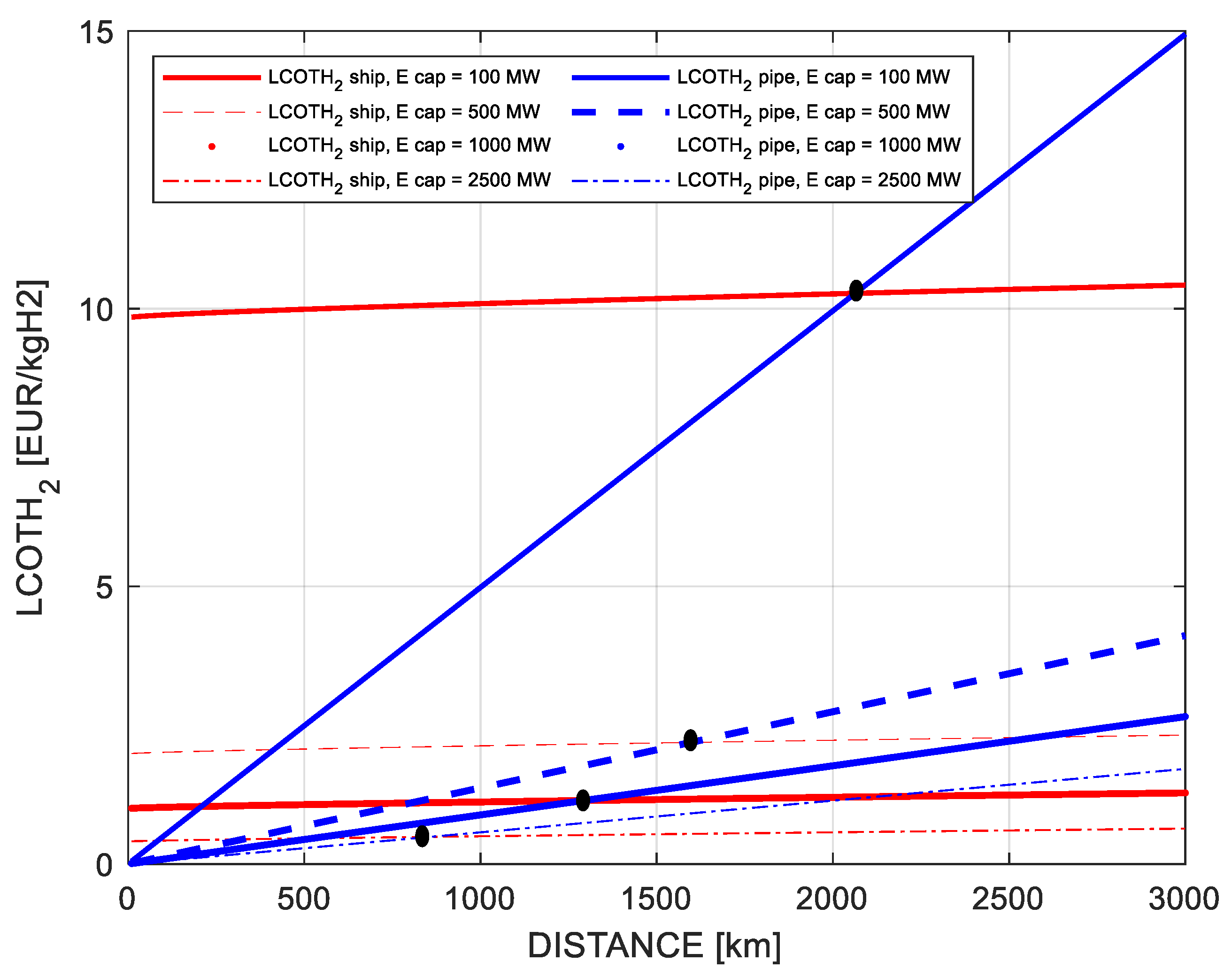
In Figure 6, the impact of varying electrolyzer capacities (100 MW, 500 MW, 1000 MW, and 2500 MW) on LCOT is presented, with transmission distance allowed to vary freely. This provides a comprehensive view of how different electrolyzer capacities and transmission distances influence the economic viability of hydrogen transport, considering both pipeline and shipping methods.
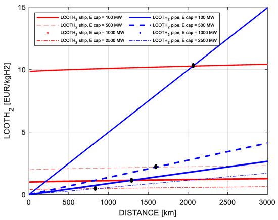
Figure 6.
LCOTH2 vs. distance to shore.
Figure 6 allows us to analyze an interesting topic, which is the breakeven point (where LCOT values for pipeline and transport are the same) between the two transportation methods for various electrolyzer capacities. For distances up to 200 km, pipelines consistently outperform LH2 tankers for all electrolyzer capacities due to their low fixed costs relative to the transported volume, making them the preferred choice for hydrogen transportation for short distances. However, as distances increase, the LCOT for pipelines rises sharply, reflecting the growing cost of installation, maintenance, recompression, and energy losses. This breakeven point is strongly influenced by electrolyzer capacity, as larger capacities enable economies of scale that can partially offset the high CAPEX of pipelines. Nonetheless, for very long distances, such as those exceeding about 2000 km, tankers generally emerge as the more cost-effective solution.
Figure 7 further explores the variation of LCOT to electrolyzer capacity for fixed distances (100 km, 500 km, 1000 km, 2000 km). This analysis complements the previous one, where the transmission distance was varied while the electrolyzer capacity was fixed, allowing a deeper understanding of how both factors influence the overall cost of hydrogen transportation.
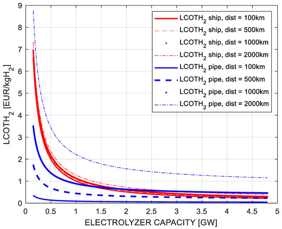
Figure 7.
LCOTH vs. electrolyzer capacity.
LCOT decreases significantly with increasing electrolyzer capacity for both pipelines and tankers. This reduction is attributed to economies of scale, where the costs per kilogram of hydrogen transported decline as the volume of hydrogen increases. For example, at 1000 km, the LCOT for pipelines starts just below EUR 1.5/kgH2 for a 500 MW electrolyzer but drops to less than EUR 0.5/kgH2 for a 5000 MW electrolyzer. The same goes for tankers; for example, at 1000 km, the LCOT varies between EUR 2.2/kgH2 and EUR 0.3/kgH2 as the capacity increases from 500 MW to 5000 MW, respectively. The cost structure of tanker-based transportation is less sensitive to distance compared with pipelines, as the bulk of the cost is associated with liquefaction, storage, and shipping operations, which are relatively independent of distance.
The most interesting trade-off is found for distances of 1000 km and above at 1.7 GW capacity, from where shipping becomes a cost-effective option for any higher installed capacity.
3.2.2. Ammonia
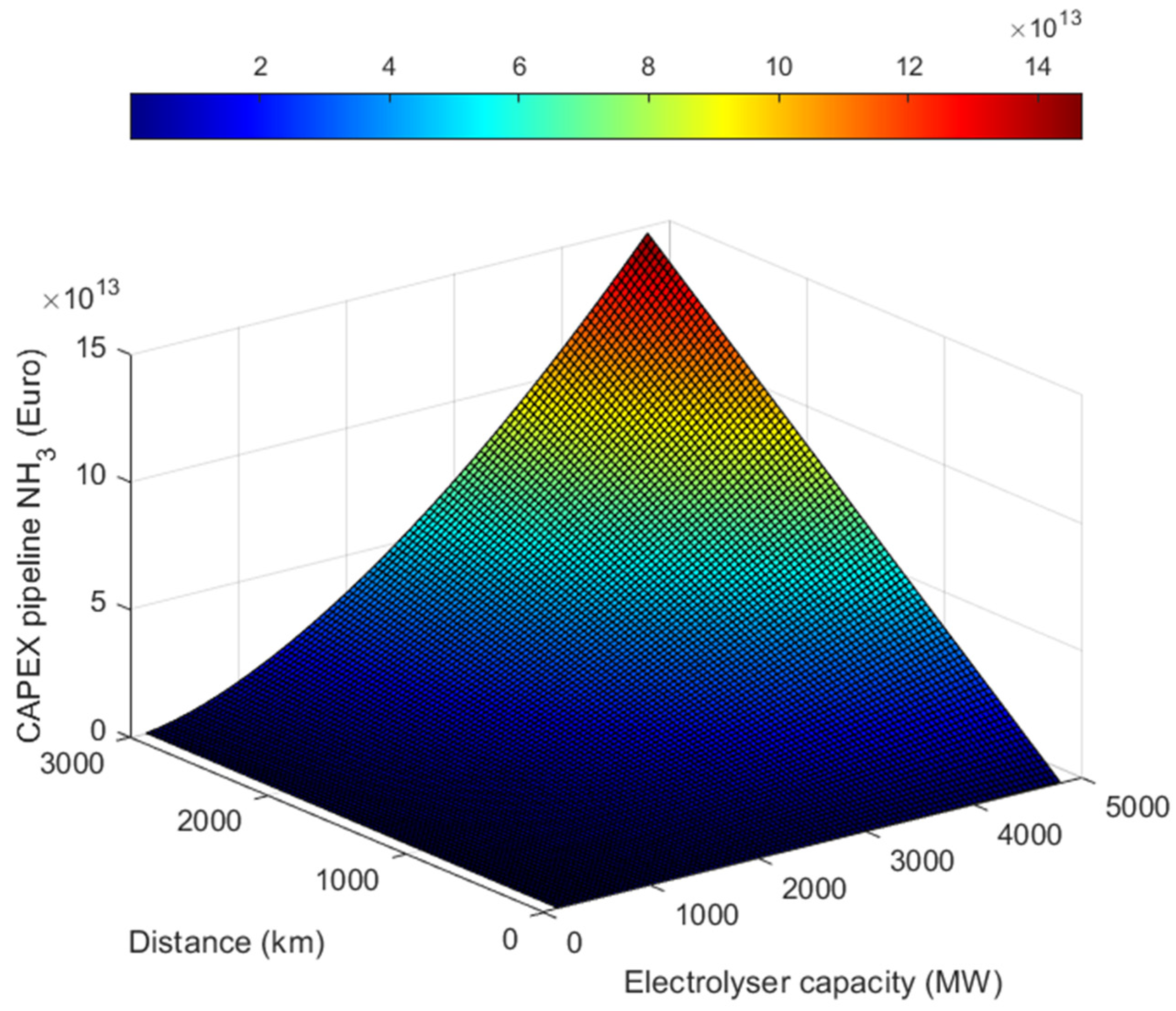
The LCOT for ammonia is evaluated by comparing pipelines and ammonia tankers under varying electrolyzer capacities and transmission distances. As previously conducted for hydrogen, Figure 8 presents a three-dimensional plot illustrating the CAPEX associated with offshore ammonia pipelines.

Figure 8.
CAPEX pipeline vs. electrolyzer capacity and distance to shore for ammonia production and transportation.
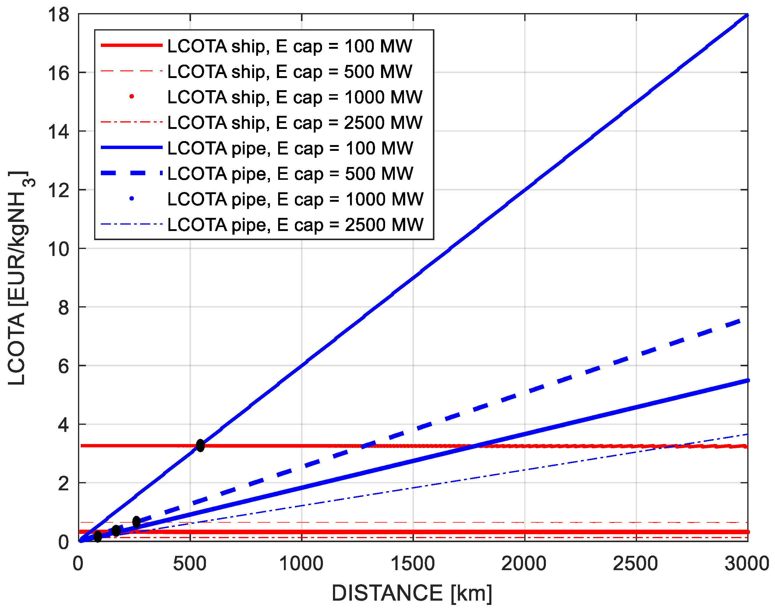
The CAPEX varies significantly with both variables, underscoring the critical importance of distance and capacity in pipeline feasibility and highlighting the challenges associated with long-distance transmission. As previously conducted for hydrogen, once the cost functions for both pipeline and shipping were defined for ammonia, two analyses were conducted. In the first analysis, the electrolyzer capacity was fixed while allowing the transmission distance to vary. In the second analysis, the transmission distance was fixed, and the electrolyzer capacity was allowed to vary. The impact of distance on LCOT for both pipelines and ammonia tankers for various electrolyzer capacities (100 MW, 500 MW, 1000 MW, 2500 MW) is shown in Figure 9.
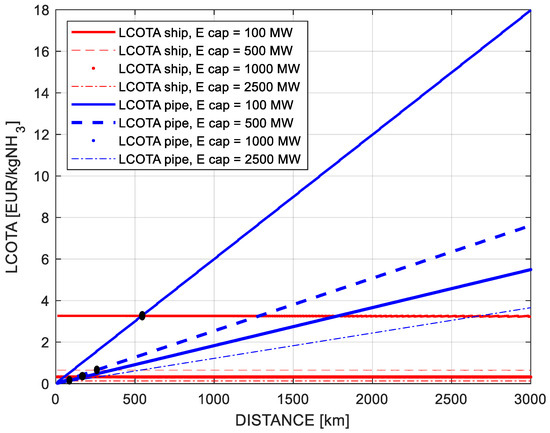
Figure 9.
LCOT vs. distance to shore.
It is noteworthy that although Equation (25) includes distance-dependent fuel costs, the LCOT for ammonia tankers remains nearly constant with distance (Figure 9). This is because fixed CAPEX for ships and storage tanks dominates the total cost. The impact of fuel consumption is marginal due to large transport volumes and the use of boil-off gas for propulsion. Additionally, while distance affects trip frequency, it does not significantly alter the cost per trip. This trend is also supported by literature [49]. The breakeven points are shown to illustrate how the scenario evolves as the electrolyzer capacity and transmission distance vary. For instance, pipelines prove to be the cost-effective option for distances below approximately 200 km for the electrolyzer capacity of 2500 MW, as the fixed costs are distributed across higher volumes of ammonia. However, beyond this breakeven distance, the LCOT for pipelines increases sharply due to rising installation, maintenance, recompression, and energy loss costs. The only case when the pipeline is clearly beneficial is for low capacity (i.e., 100 MW) for distances below 400 km. Otherwise, ammonia shipping results in being the clear winner on economic terms.
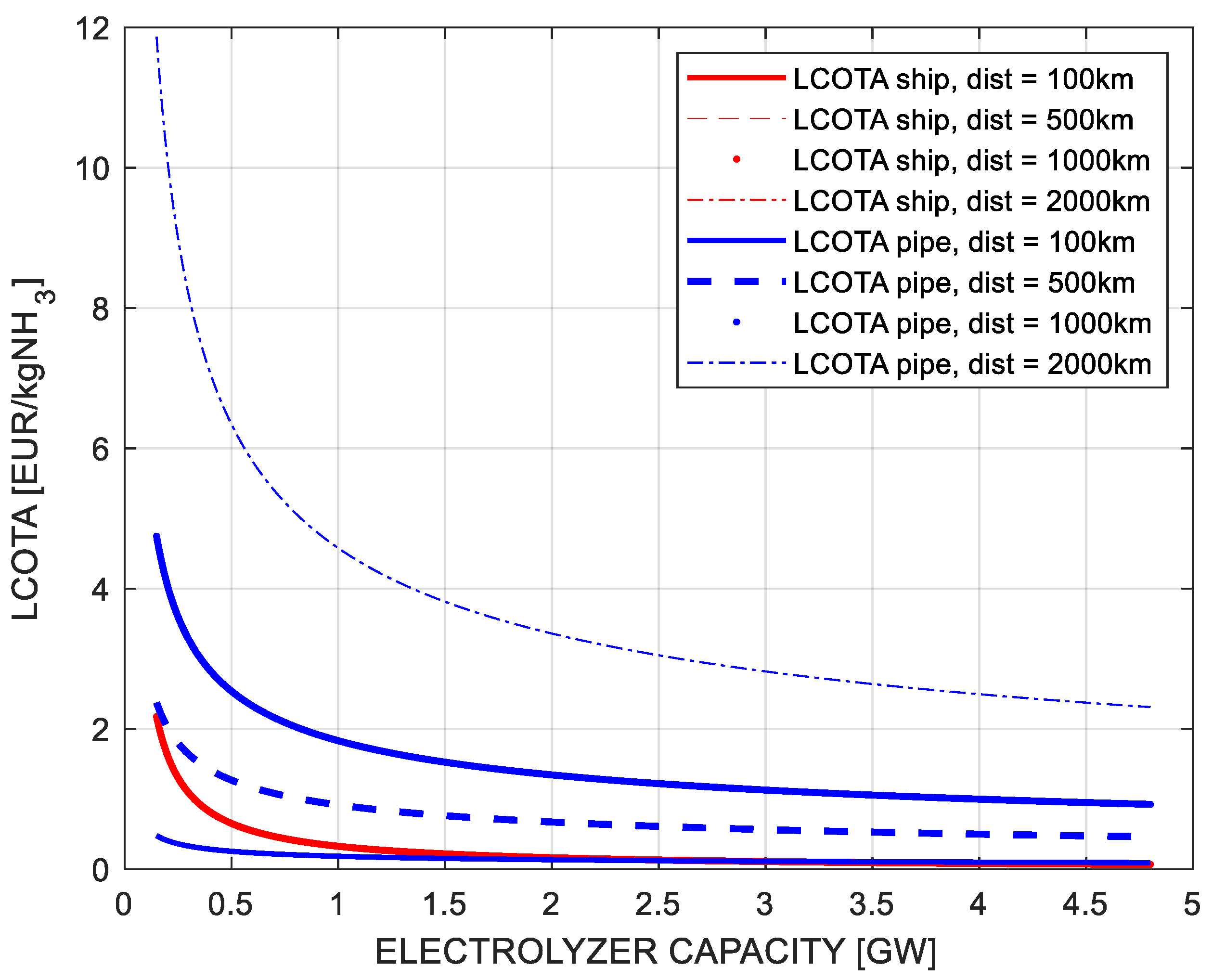
Figure 10 explores LCOT sensitivity to electrolyzer capacity at fixed distances (100 km, 500 km, 1000 km, 2000 km).
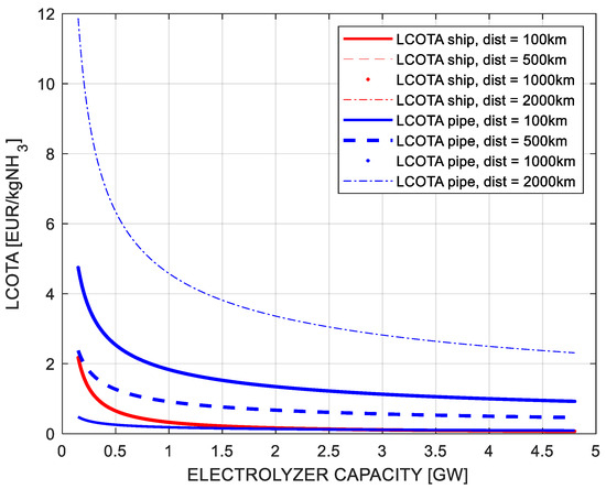
Figure 10.
LCOT vs. electrolyzer capacity.
At 1000 km, LCOT for pipelines drops from over EUR 4.8/kgNH3 (100 MW) to below EUR 1/kgNH3 (4800 MW), highlighting economies of scale. For 100 km, LCOT for pipelines is cheaper than shipping up to an electrolyzer capacity of 2.3 GW. In contrast, ammonia tankers remain cost-effective for distances 100 km onward and for electrolyzer capacities beyond 2.3 GW, making them a favorable option for ammonia transport.
3.3. Total Levelized Cost After Transport for Hydrogen and Ammonia
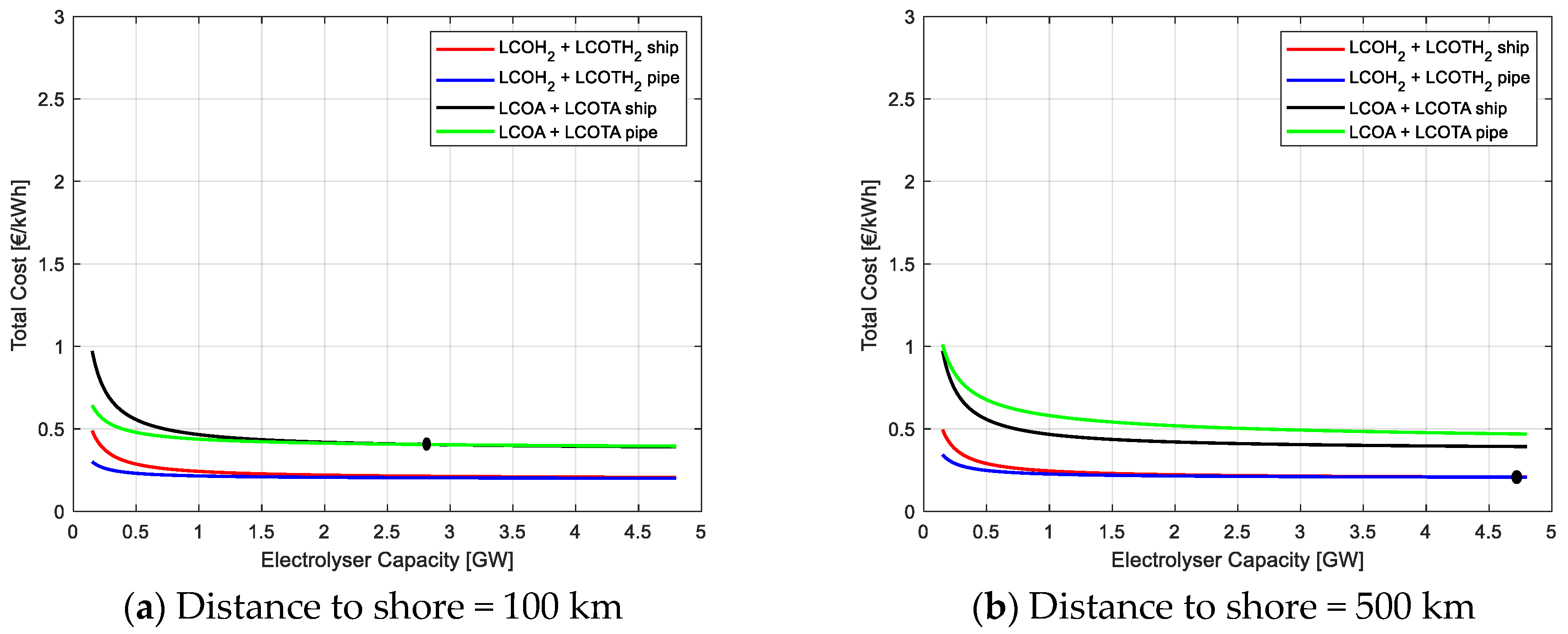
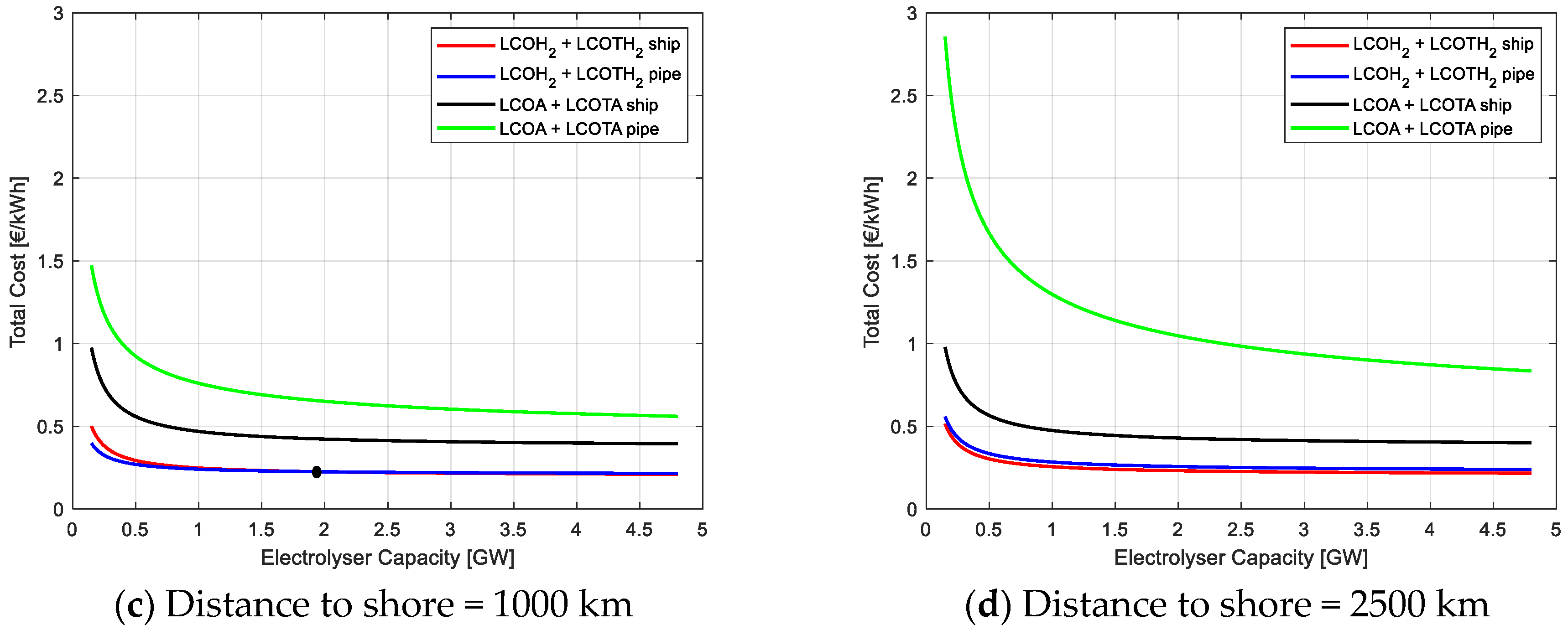
An additional step in the analysis includes the addition of LCOH2/A and LCOT in order to evaluate the Total Cost After Transport, this is illustrated in Figure 11.
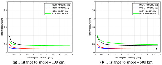
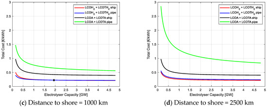
Figure 11.
LCOH2/A + LCOT for different distances to shore.
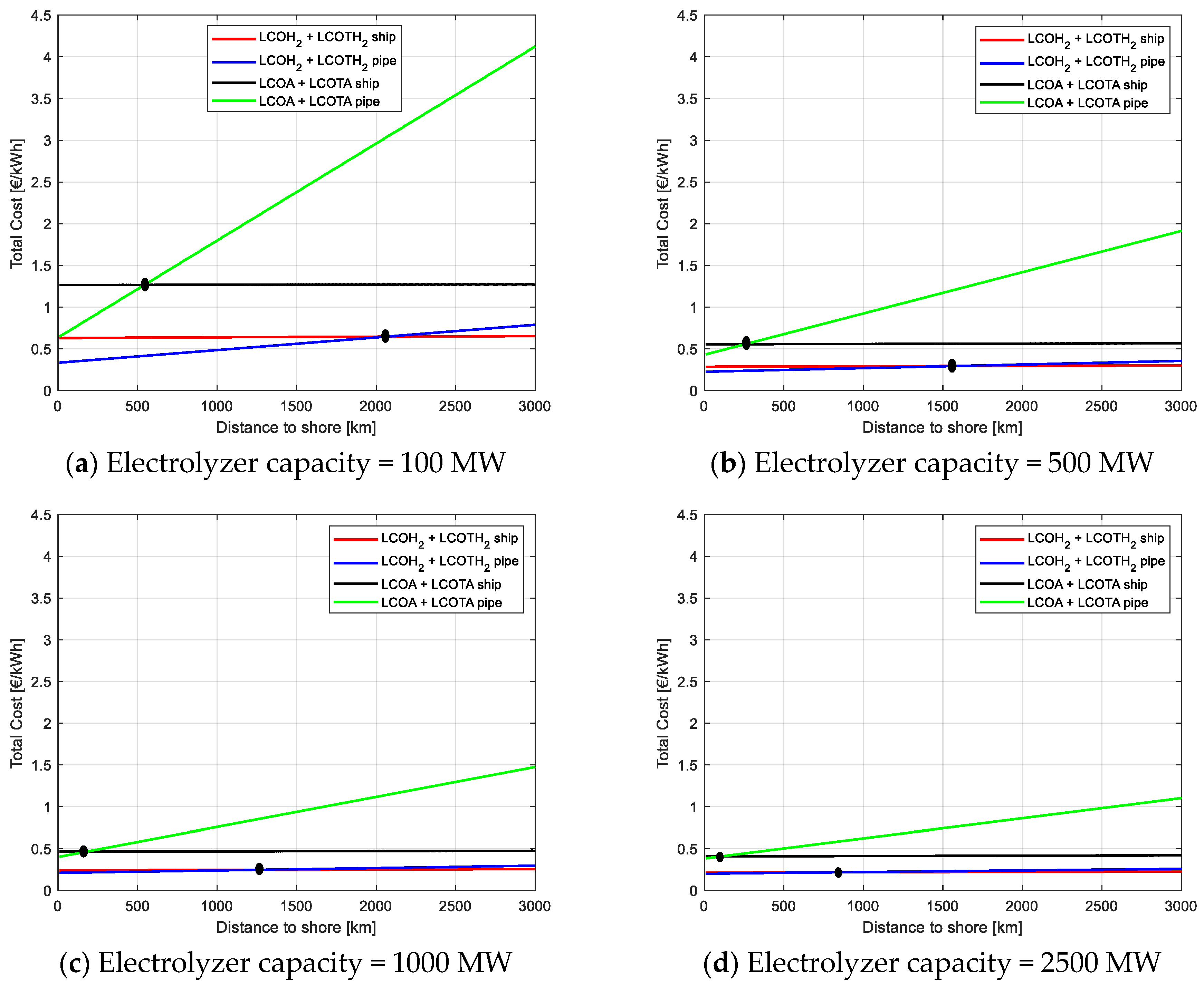
Figure 11 displays the combined LCOH2 and LCOA values with LCOT for fixed distances to shore while varying the electrolyzer capacity. In Figure 11a,b, i.e., distances lower than 500 km, pipeline transport remains favorable for hydrogen for all electrolyzer capacities. Shipping is preferred for ammonia transport beyond the distance of 100 km for all electrolyzer capacities and distances taken in this study. Similarly, above 500 km, ammonia shipping emerges as the most cost-effective solution, while hydrogen shipping is still expensive compared with ammonia. Figure 12 better shows the impact of distance on the total cost after transport since it is built for fixed electrolyzer capacities with varying distance.
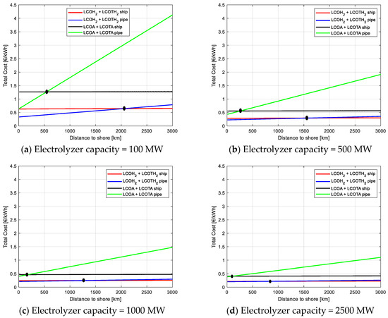
Figure 12.
LCOH2/A + LCOT for different electrolyzer capacities.
Figure 12a indicates that hydrogen transport is generally cheaper than ammonia due to the higher energy content. Particularly, hydrogen pipelines are the best option up to 2000 km, after which distance hydrogen shipping becomes the optimal solution.
A similar effect can be seen in Figure 12b; this time the breakeven point is reached at about 1600 km when hydrogen shipping becomes more beneficial than pipelines. This trend is confirmed as the electrolyzer capacity continues to increase while the breakeven distance between hydrogen transport through pipelines and shipping becomes lower. This highlights that the choice between pipeline and shipping should consider not only distance but also the scale of hydrogen and ammonia production to optimize overall costs and efficiency.
Sensitivity Analysis of the Total Levelized Costs After Transport
The results obtained from the sensitivity analysis are calculated only for hydrogen since, in all the analyzed cases, it resulted in being the best option when transported both via pipelines and shipping. The selected parameters were chosen for their relevance to offshore Power-to-X systems and their expected variability in real-world applications. In all figures, the reference value is depicted with a continuous line, while the best and worst scenarios, as per Table 2, are shown with dashed lines. For the sake of clarity, two relevant electrolyzer sizes have been considered that are 100 MW and 1000 MW, whose variation is depicted against the distance to shore in the X-axis.
The capacity factor of the offshore wind farm represents the ratio between actual and theoretical maximum power output over a given period. This parameter is largely dependent on the site-specific wind conditions, which dictate the amount of energy generated over a given period. Results are shown in Figure 13.
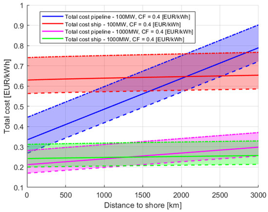
Figure 13.
Total levelized cost of hydrogen after transport with varying capacity factors. Dashed lines are the limits of the sensitivity analysis that are CF of 0.5 and 0.3.
Figure 13 shows that increasing the CF from 30% to 50% leads to a reduction in the total levelized cost of hydrogen after transport that ranges between 10 and 22%, with a higher decrease for the case with 1000 MW capacity, while the lowest improvement is seen for 100 MW transported via ship. On the other hand, the increase in the total levelized cost of hydrogen after transport increases by 17–32% with a CF reduction. The increase is larger for pipeline transportation and particularly for the 100 MW size. This significant cost drop with higher CF reflects the improved utilization of wind energy; more hydrogen is produced with the same capital investment, spreading costs over a larger output. Conversely, low CF values lead to underutilized assets and higher unit costs.
Another important parameter that can influence the system economy is the efficiency of the PEM electrolyzer, which is a critical determinant of the LCOH2. Technological advancements continue to improve electrolyzer efficiency; a reduction in efficiency could arise from factors such as system degradation over time and harsh operating conditions in offshore environments. These inefficiencies increase the overall energy demand, negatively impacting the economic feasibility of hydrogen production.
Figure 14 illustrates the impact of efficiency variation; an improvement from 50% to 70% directly translates to a reduced energy input per unit of hydrogen produced, leading to lower costs in the range of 8–14%.
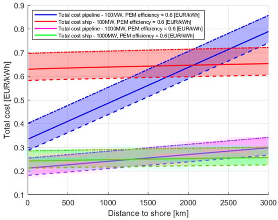
Figure 14.
Total levelized cost of hydrogen after transportation with varying PEM efficiency vs. distance to shore. Dashed lines are the limits of the sensitivity analysis that are PEM efficiencies of 0.7 and 0.5.
Once again, the negative effect of a lower efficiency results in being higher than the positive impact in the case of higher efficiency. Indeed, the total levelized cost of hydrogen after transport is increased by about 11–18% in case the average efficiency drops to 50%.
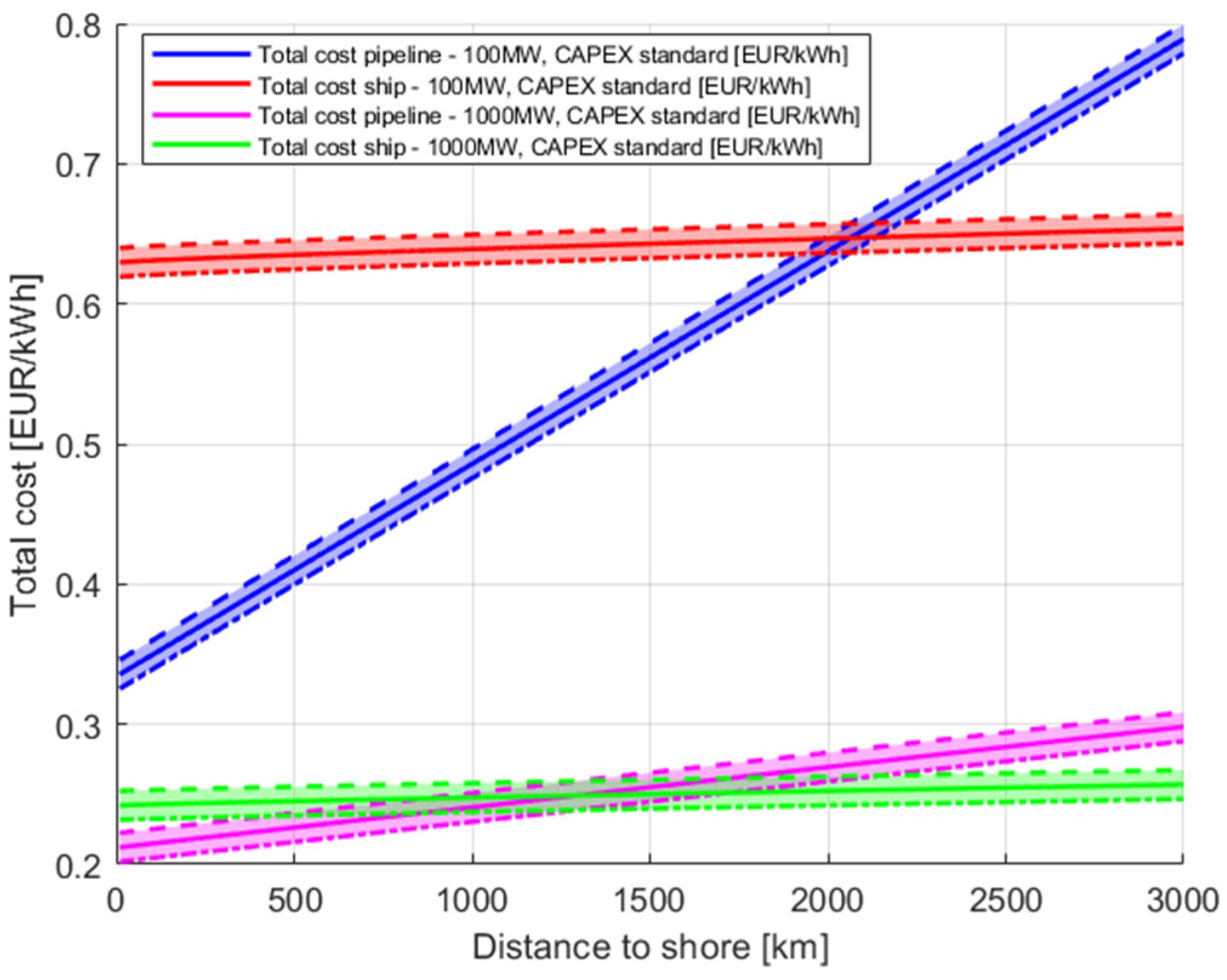
Capital costs for wind turbines and their supporting platforms represent the largest share of investment in offshore hydrogen production systems, typically 50–60% of total costs. These values may vary due to site conditions, technology choices (e.g., floating vs. fixed-bottom), and supply chain maturity. Because of their high weight in the cost structure, even moderate changes in CAPEX can heavily influence production costs.
Figure 15 shows that a 20% increase in the CAPEX for turbines and platforms affects costs less significantly than CF and PEM efficiency and affects the total LCOH2 in the same way in the case of both an increase or a decrease.

Figure 15.
Total levelized cost of hydrogen after transportation with varying wind turbine and platform CAPEX vs. distance to shore. Dashed lines are the limit of the sensitivity analysis that is for a CAPEX of ±20%.
Although electrolyzer CAPEX is lower than that of wind infrastructure, it still represents a significant portion of total investment and is subject to variability based on scale, integration strategies, and technological choices, as shown in Figure 16.
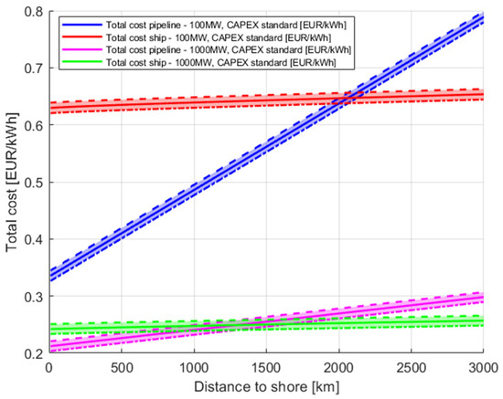
Figure 16.
Total levelized cost of hydrogen after transportation with varying electrolyzer and platform CAPEX vs. distance to shore. Dashed lines are the limit of the sensitivity analysis that is for a CAPEX of ±20%.
Figure 16 shows that the impact of electrolyzer CAPEX is less relevant than other parameters. Nevertheless, this result does not discourage the value of innovation in electrolyzer manufacturing and offshore integration for improving the overall economics of hydrogen and ammonia production.
The results obtained from the sensitivity analysis identified the wind farm and electrolyzer CAPEXs as having a significant impact on production costs. Nevertheless, these two parameters do not account for the majority of the observed cost variations. In contrast, the choice of a higher CF and improvements in the efficiency of the electrolyzer yield comparatively higher reductions in cost. This is probably due to the fact that an increased investment cost can be amortized along the whole system’s lifetime, while the efficiency and capacity factors have an impact on the whole system’s working period.
These findings have highlighted that the selection of locations with high wind resource availability remains the most important driver for competitive costs. In addition to site selection, it would be preferable to enhance the CF even if this would lead to higher CAPEX; of course, a trade-off should be found on a case-by-case basis. The capacity factor can be improved by optimizing the wind farm layout, minimizing wake effects, and implementing advanced control strategies such as active yaw and pitch regulation. At the same time, reducing the capital costs of offshore infrastructure through innovations in turbine design, modular platforms, or optimized installation logistics still plays a key role in enhancing overall economic feasibility. The use of alternative foundation materials such as concrete, which can be locally produced and offer lower costs compared with steel, may contribute to this reduction. Moreover, investments in port infrastructure, such as facilities for pre-assembly, storage, and streamlined transport, can significantly reduce construction and deployment times, leading to further CAPEX savings.
3.4. Discussion and Comparison of Results
This section presents a comparative overview of the results obtained in this study against a selection of relevant literature. In this study, a broad set of scenarios was explored by varying both the distance and the electrolyzer capacity and considering both pipeline and shipping solutions. This allowed for a more comprehensive assessment of how scale and logistics influence the overall cost structure, particularly in relation to transport. Compared with prior studies such as [30], our analysis yields lower transport costs due to updated CAPEX figures and dynamic sizing of pipeline diameter based on electrolyzer capacity. Unlike other studies such as [18,32,38] focusing solely on one energy carrier, our work uniquely compares hydrogen and ammonia across varying distances and capacities. Also, studies such as [43] only estimate transport costs (LCOTA) without integrating production costs (LCOH2, LCOA). The dual analysis of this study (LCOH2/A and LCOT) provides practical guidance for optimizing offshore energy carrier strategies.
Particularly, in this study, the estimated LCOH2 ranges between 6.7 and 9.8 EUR/kg, while the LCOA varies from 1.9 to 2.8 EUR/kg. The LCOT shows significant variability, ranging from 0.2 to 15 EUR/kg for pipeline and from 0.3 to 10.2 EUR/kg for shipping, highlighting the strong influence of distance and scale on overall costs. Table 3 summarizes the obtained results and compares them with the results of other relevant studies in the literature.
Table 3.
Comparison of selected studies from the literature with this work.
Although methodological approaches and boundary conditions vary across studies, the results presented here align with the general trends observed in the literature. In particular, the cost ranges are shown to be highly sensitive to assumptions regarding system scale and transport technology.
4. Conclusions
In this study, a techno-economic analysis was conducted to assess the feasibility of hydrogen and ammonia production and transportation. The results demonstrate that economies of scale play a crucial role in reducing both production and transport costs, with larger electrolyzer capacities leading to lower LCOH2 and LCOA, which currently are not competitive with conventional fossil fuel-based production. The analysis for combined LCOH2 and LCOA with LCOT reveals that pipelines are the cheapest source of transportation for both hydrogen and ammonia for distances up to 500 km. For longer distances, the analysis of LCOH2/A combined with LCOT results in favor of hydrogen, particularly for pipelines for shorter distances and shipping for longer distances and higher volumes of transported hydrogen. The sensitivity analysis shows the importance of various factors in determining the production costs of hydrogen and ammonia in an offshore setting. In particular, the capacity factor of offshore wind and electrolyzer efficiency have higher importance than CAPEX of electrolyzers and turbines. This result can be an important factor in strategizing investment for realization and also for R&D development.
Offshore wind-based hydrogen and its derivates, such as ammonia, present a promising decarbonization pathway for sectors such as transport and industry. Strategic planning of offshore energy infrastructure, considering not only cost but also technical feasibility, regulatory requirements, and developments in storage and transport technologies, is crucial to achieving the potential benefits. The study recommends the importance of further research into hydrogen liquefaction, compression, and ammonia technologies, which could significantly impact the competitiveness of different transport options.
The results obtained can support investors and planners in identifying the optimal solution based on the final use of hydrogen and ammonia, either as feedstocks or energy vectors, on the size of the plants, on the volume of transported goods, and on the distance traveled. Indeed, given the importance of all these features, it is important to take them all into consideration for an optimal decision.
Future developments should focus on enhancing the efficiency of transmission systems and exploring hybrid solutions that combine power transmission lines with either pipelines or shipping for improved flexibility. Additionally, policy frameworks should be adopted to support the deployment of cost-effective, flexible, and scalable transport solutions, ensuring the long-term sustainability of offshore hydrogen and ammonia as key enablers of the energy transition.
Supplementary Materials
The following supporting information can be downloaded at: https://www.mdpi.com/article/10.3390/en18092292/s1, Table S1: Coefficients used for foundation costs of wind turbines; Table S2: Cost parameters of electrolysis systems; Table S3: Techno-economic assumptions for inter-array cables; Table S4: Parameters for hydrogen plant, pipeline and shipping; Table S5: benchmark tanker information; Table S6: LH2 tanker assumptions and parameters used References [64,65,66,67,68,69,70,71,72,73,74,75] are cited in the supplementary materials.
Author Contributions
Conceptualization, F.H.J., D.G. and D.A.G.; Data curation, F.H.J.; Formal analysis, F.H.J.; Methodology, D.G., A.S.S. and D.A.G.; Project administration, D.G. and D.A.G.; Resources, D.G. and D.A.G.; Software, A.F.; Supervision, D.G. and D.A.G.; Validation, D.G. and D.A.G.; Visualization, A.S.S. and D.G.; Writing—Original draft, F.H.J. and A.F.; Writing—Review and editing, A.F., D.G., A.S.S. and D.A.G. All authors have read and agreed to the published version of the manuscript.
Funding
This research is funded by the Interreg Euro-MED Green Living Areas program as part of the “SPOWIND—Spatial Planning for Offshore Wind Industry Development” project (Project ID: Euro-MED0200199).
Data Availability Statement
The original contributions presented in this study are included in the article/Supplementary Materials. Further inquiries can be directed to the corresponding author.
Conflicts of Interest
The authors declare no conflicts of interest.
Abbreviations
The following abbreviations are used in this manuscript:
| ASU | Air Separation Unit |
| CAPEX | Capital Expenditure |
| CO2eq | Carbon Dioxide Equivalent |
| DECEX | Decommissioning Expenditure |
| FLCOA | Final Levelized Cost of Ammonia |
| FLCOH2 | Final Levelized Cost of Hydrogen |
| HB | Haber–Bosch |
| HVAC | High Voltage Alternating Current |
| HVDC | High Voltage Direct Current |
| IC | Installation Cost |
| IRENA | International Renewable Energy Agency |
| LCOA | Levelized Cost of Ammonia |
| LCOH2 | Levelized Cost of Hydrogen |
| LCOT | Levelized Cost of Transport |
| LCOTH | Levelized Cost of Transport for Hydrogen |
| LH2 | Liquid Hydrogen |
| LHV | Lower Heating Value |
| LNG | Liquefied Natural Gas |
| LPG | Liquefied Petroleum Gas |
| MCH | Methylcyclohexane |
| NPV | Net Present Value |
| OPEX | Operational Expenditure |
| OWHS | Offshore Wind Hydrogen Systems |
| OWP2A | Offshore Wind Power to Ammonia |
| OWP2H | Offshore Wind Power to Hydrogen |
| PEM | Proton Exchange Membrane |
| SMR | Steam Methane Reforming |
| Tcap | Tanker Capacity |
| Vship | Vessel Speed |
References
- Gür, T.M. Review of electrical energy storage technologies, materials and systems: Challenges and prospects for large-scale grid storage. Energy Environ. Sci. 2018, 11, 2696–2767. [Google Scholar] [CrossRef]
- Cesaro, Z.; Nayak-Luke, R.M.; Bañares-Alcántara, R. Chapter 2—Energy Storage Technologies: Power-to-X. In Techno-Economic Challenges of Green Ammonia as an Energy Vector; Valera-Medina, A., Banares-Alcantara, R., Eds.; Academic Press: Cambridge, MA, USA, 2021; pp. 15–26. [Google Scholar] [CrossRef]
- Green Hydrogen A Guide To Policy Making. Irena. Available online: https://www.irena.org/-/media/Files/IRENA/Agency/Publication/2020/Nov/IRENA_Green_hydrogen_policy_2020.pdf (accessed on 3 March 2025).
- Davis, S.J.; Lewis, N.S.; Shaner, M.; Aggarwal, S.; Arent, D.; Azevedo, I.L.; Benson, S.M.; Bradley, T.; Brouwer, J.; Chiang, Y.-M.; et al. Net-zero emissions energy systems. Science 2018, 360, eaas9793. [Google Scholar] [CrossRef] [PubMed]
- Mazloomi, K.; Gomes, C. Hydrogen as an energy carrier: Prospects and challenges. Renew. Sustain. Energy Rev. 2012, 16, 3024–3033. [Google Scholar] [CrossRef]
- Carbo, M.C. Global Technology Roadmap for CCS in Industry; United Nations Industrial Development Organization: Vienna, Austria, 2011. [Google Scholar]
- Aneke, M.; Wang, M. Energy storage technologies and real life applications—A state of the art review. Appl. Energy 2016, 179, 350–377. [Google Scholar] [CrossRef]
- Agency, I.E. Towards Hydrogen Definitions Based on Their Emissions Intensity; OECD: Paris, France, 2023. [Google Scholar] [CrossRef]
- Communication COM/2020/301: A Hydrogen Strategy for a Climate-Neutral Europe|Knowledge for Policy. Available online: https://knowledge4policy.ec.europa.eu/publication/communication-com2020301-hydrogen-strategy-climate-neutral-europe_en (accessed on 13 December 2024).
- Geopolitics of the Energy Transformation: The Hydrogen Factor. Available online: https://www.irena.org/publications/2022/Jan/Geopolitics-of-the-Energy-Transformation-Hydrogen (accessed on 15 July 2024).
- Chatterjee, S.; Parsapur, R.K.; Huang, K.-W. Limitations of Ammonia as a Hydrogen Energy Carrier for the Transportation Sector. ACS Energy Lett. 2021, 6, 4390–4394. [Google Scholar] [CrossRef]
- Kleinman Center for Energy Policy. Ammonia’s Role in a Net-Zero Hydrogen Economy. Available online: https://kleinmanenergy.upenn.edu/research/publications/ammonias-role-in-a-net-zero-hydrogen-economy/ (accessed on 27 January 2025).
- Avery, W.H. A role for ammonia in the hydrogen economy. Int. J. Hydrogen Energy 1988, 13, 761–773. [Google Scholar] [CrossRef]
- Wijayanta, A.T.; Oda, T.; Purnomo, C.W.; Kashiwagi, T.; Aziz, M. Liquid hydrogen, methylcyclohexane, and ammonia as potential hydrogen storage: Comparison review. Int. J. Hydrogen Energy 2019, 44, 15026–15044. [Google Scholar] [CrossRef]
- Dong, C.; Huang, G.; Cheng, G. Offshore wind can power Canada. Energy 2021, 236, 121422. [Google Scholar] [CrossRef]
- Wang, Y.; Dong, G.; Yu, J.; Qin, C.; Feng, Y.; Deng, Y.; Zhang, M. In-situ green hydrogen production from offshore wind farms, a prospective review. Renew. Energy 2025, 239, 122099. [Google Scholar] [CrossRef]
- Huang, J.; Balcombe, P.; Feng, Z. Technical and economic analysis of different colours of producing hydrogen in China. Fuel 2023, 337, 127227. [Google Scholar] [CrossRef]
- Hill, S.J.P.; Bamisile, O.; Hatton, L.; Staffell, I.; Jansen, M. The cost of clean hydrogen from offshore wind and electrolysis. J. Clean. Prod. 2024, 445, 141162. [Google Scholar] [CrossRef]
- Alsir, A. Making the Breakthrough: Green Hydrogen Policies and Technology Costs; Energy Oman Magazine: Muscat, Oman, 2023. [Google Scholar]
- Poshydon|Green Hydrogen Energy. Available online: https://poshydon.com/en/home-en/ (accessed on 14 December 2024).
- Hydrogen Island. Available online: https://www.cip.com/approach/our-projects/hydrogen-island/ (accessed on 13 December 2024).
- NortH2|Kickstarting the Green Hydrogen Economy. Available online: https://www.north2.eu/ (accessed on 14 December 2024).
- AquaVentus Förderverein e.V. Available online: https://aquaventus.org/en/ (accessed on 14 December 2024).
- Dolphyn Hydrogen. Available online: https://www.dolphynhydrogen.com/ (accessed on 14 December 2024).
- El-Kady, A.H.; Amin, M.T.; Khan, F.; El-Halwagi, M.M. Identification and assessment of risk factors in offshore wind-integrated hydrogen production system. Int. J. Hydrogen Energy 2024, 52, 1312–1332. [Google Scholar] [CrossRef]
- Ramakrishnan, S.; Delpisheh, M.; Convery, C.; Niblett, D.; Vinothkannan, M.; Mamlouk, M. Offshore green hydrogen production from wind energy: Critical review and perspective. Renew. Sustain. Energy Rev. 2024, 195, 114320. [Google Scholar] [CrossRef]
- Dinh, V.N.; Leahy, P.; McKeogh, E.; Murphy, J.; Cummins, V. Development of a viability assessment model for hydrogen production from dedicated offshore wind farms. Int. J. Hydrogen Energy 2021, 46, 24620–24631. [Google Scholar] [CrossRef]
- Yan, Y.; Zhang, H.; Liao, Q.; Liang, Y.; Yan, J. Roadmap to hybrid offshore system with hydrogen and power co-generation. Energy Convers. Manag. 2021, 247, 114690. [Google Scholar] [CrossRef]
- Bonacina, C.N.; Gaskare, N.B.; Valenti, G. Assessment of offshore liquid hydrogen production from wind power for ship refueling. Int. J. Hydrogen Energy 2022, 47, 1279–1291. [Google Scholar] [CrossRef]
- Zhao, F.; Wang, Z.; Dong, B.; Li, M.; Ji, Y.; Han, F. Comprehensive life cycle cost analysis of ammonia-based hydrogen transportation scenarios for offshore wind energy utilization. J. Clean. Prod. 2023, 429, 139616. [Google Scholar] [CrossRef]
- Cava, C.; Gagliardi, G.G.; Piscolla, E.; Borello, D. Techno-Economic Analysis of Hydrogen Transport via Truck Using Liquid Organic Hydrogen Carriers. Processes 2025, 13, 1081. [Google Scholar] [CrossRef]
- Giampieri, A.; Ling-Chin, J.; Roskilly, A.P. Techno-economic assessment of offshore wind-to-hydrogen scenarios: A UK case study. Int. J. Hydrogen Energy 2024, 52, 589–617. [Google Scholar] [CrossRef]
- Gonzalez-Arceo, A.; Blanco-Aguilera, R.; Berasategi, J.; Martinez-Agirre, M.; Martinez, A.; Iglesias, G.; Penalba, M. Techno-economic assessment of far-offshore hydrogen-carrying energy vectors off the Iberian Peninsula. Energy Convers. Manag. 2024, 300, 117915. [Google Scholar] [CrossRef]
- Sage, V.; Patel, J.; Hazewinkel, P.; Yasin, Q.U.A.; Wang, F.; Yang, Y.; Kozielski, K.; Li, C. Recent progress and techno-economic analysis of liquid organic hydrogen carriers for Australian renewable energy export—A critical review. Int. J. Hydrogen Energy 2024, 56, 1419–1434. [Google Scholar] [CrossRef]
- Lucas, T.R.; Ferreira, A.F.; Pereira, R.B.S.; Alves, M. Hydrogen production from the WindFloat Atlantic offshore wind farm: A techno-economic analysis. Appl. Energy 2022, 310, 118481. [Google Scholar] [CrossRef]
- Jang, D.; Kim, K.; Kim, K.-H.; Kang, S. Techno-economic analysis and Monte Carlo simulation for green hydrogen production using offshore wind power plant. Energy Convers. Manag. 2022, 263, 115695. [Google Scholar] [CrossRef]
- Salmon, N.; Bañares-Alcántara, R. Green ammonia as a spatial energy vector: A review. Sustain. Energy Fuels 2021, 5, 2814–2839. [Google Scholar] [CrossRef]
- Kim, A.; Kim, H.; Choe, C.; Lim, H. Feasibility of offshore wind turbines for linkage with onshore green hydrogen demands: A comparative economic analysis. Energy Convers. Manag. 2023, 277, 116662. [Google Scholar] [CrossRef]
- Bai, R.; Cai, G.; Chen, X.; Nie, S.; Zhou, Z.; Gao, L.; Wang, P. Enriching wind power utility through offshore wind-hydrogen-chemicals nexus: Feasible routes and their economic performance. J. Clean. Prod. 2024, 476, 143732. [Google Scholar] [CrossRef]
- Singlitico, A.; Østergaard, J.; Chatzivasileiadis, S. Onshore, offshore or in-turbine electrolysis? Techno-economic overview of alternative integration designs for green hydrogen production into Offshore Wind Power Hubs. Renew. Sustain. Energy Transit. 2021, 1, 100005. [Google Scholar] [CrossRef]
- Wang, H.; Daoutidis, P.; Zhang, Q. Harnessing the Wind Power of the Ocean with Green Offshore Ammonia. ACS Sustain. Chem. Eng. 2021, 9, 14605–14617. [Google Scholar] [CrossRef]
- Hong, X.; Thaore, V.B.; Karimi, I.A.; Farooq, S.; Wang, X.; Usadi, A.K.; Chapman, B.R.; Johnson, R.A. Techno-enviro-economic analyses of hydrogen supply chains with an ASEAN case study. Int. J. Hydrogen Energy 2021, 46, 32914–32928. [Google Scholar] [CrossRef]
- De Almeida, J.O.; Shadman, M.; Ramos, J.d.S.; Bastos, I.T.C.; Silva, C.; Chujutalli, J.A.H.; Amiri, M.M.; Bergman-Fonte, C.; Ferreira, G.R.L.; Carreira, E.d.S.; et al. Techno-economic analysis of hydrogen production from offshore wind: The case of Brazil. Energy Convers. Manag. 2024, 322, 119109. [Google Scholar] [CrossRef]
- Song, S.; Lin, H.; Sherman, P.; Yang, X.; Nielsen, C.P.; Chen, X.; McElroy, M.B. Production of hydrogen from offshore wind in China and cost-competitive supply to Japan. Nat. Commun. 2021, 12, 6953. [Google Scholar] [CrossRef] [PubMed]
- Spatolisano, E.; Restelli, F.; Pellegrini, L.A.; Cattaneo, S.; de Angelis, A.R.; Lainati, A.; Roccaro, E. Liquefied hydrogen, ammonia and liquid organic hydrogen carriers for harbour-to-harbour hydrogen transport: A sensitivity study. Int. J. Hydrogen Energy 2024, 80, 1424–1431. [Google Scholar] [CrossRef]
- Jano-Ito, M.; Valera-Medina, A. Techno-economics of ammonia as an energy carrier. Exporting wind from the North Atlantic Ocean/North Sea to Wales. J. Ammon. Energy 2024, 2. [Google Scholar] [CrossRef]
- Peecock, A.; Hull-Bailey, B.; Hastings, A.; Martinez-Felipe, A.; Wilcox, L.B. Techno-economic assessment of liquid carrier methods for intercontinental shipping of hydrogen: A case study. Int. J. Hydrogen Energy 2024, 94, 971–983. [Google Scholar] [CrossRef]
- Niblett, D.; Delpisheh, M.; Ramakrishnan, S.; Mamlouk, M. Review of next generation hydrogen production from offshore wind using water electrolysis. J. Power Sources 2023, 592, 233904. [Google Scholar] [CrossRef]
- Dinh, Q.V.; Pereira, P.H.T.; Dinh, V.N.; Nagle, A.J.; Leahy, P.G. Levelised cost of transmission comparison for green hydrogen and ammonia in new-build offshore energy infrastructure: Pipelines, tankers, and HVDC. Int. J. Hydrogen Energy 2024, 62, 684–698. [Google Scholar] [CrossRef]
- Topham, E.; McMillan, D.; Bradley, S.; Hart, E. Recycling offshore wind farms at decommissioning stage. Energy Policy 2019, 129, 698–709. [Google Scholar] [CrossRef]
- Rogeau, A.; Vieubled, J.; De Coatpont, M.; Nobrega, P.A.; Erbs, G.; Girard, R. Techno-economic evaluation and resource assessment of hydrogen production through offshore wind farms: A European perspective. Renew. Sustain. Energy Rev. 2023, 187, 113699. [Google Scholar] [CrossRef]
- Baufumé, S.; Grüger, F.; Grube, T.; Krieg, D.; Linssen, J.; Weber, M.; Hake, J.-F.; Stolten, D. GIS-based scenario calculations for a nationwide German hydrogen pipeline infrastructure. Int. J. Hydrogen Energy 2013, 38, 3813–3829. [Google Scholar] [CrossRef]
- Redactoramexico. Siemens Commissions One of Germany’s Largest Green Hydrogen Generation Plants. Hydrogen Central. Available online: https://hydrogen-central.com/siemens-commissions-germanys-largest-green-hydrogen-generation-plants/ (accessed on 16 January 2025).
- Bai, Y.; Bai, Q. Subsea Engineering Handbook; Gulf Professional Publishing: Houston, TX, USA, 2010. [Google Scholar]
- News & Events. Kawasaki Heavy Industries, Ltd. Available online: https://global.kawasaki.com/en/corp/newsroom/news/detail/?f=20191211_3487 (accessed on 15 July 2024).
- Current Status of Hydrogen Liquefaction Costs. Department of Energy, USA. August 2019. Available online: https://www.hydrogen.energy.gov/docs/hydrogenprogramlibraries/pdfs/19001_hydrogen_liquefaction_costs.pdf?Status=Master (accessed on 15 January 2025).
- Li, Y. Optimising Liquefied Natural Gas [LNG] Supply Chains: A Case Study for China. Master’s Dissertation, World Maritime University, Malmö, Sweden, 2002. Available online: https://commons.wmu.se/all_dissertations/378 (accessed on 16 February 2025).
- Rouwenhorst, K.H.R.; Krzywda, P.M.; Benes, N.E.; Mul, G.; Lefferts, L. Chapter 4—Ammonia Production Technologies. In Techno-Economic Challenges of Green Ammonia as an Energy Vector; Valera-Medina, A., Banares-Alcantara, R., Eds.; Academic Press: Cambridge, MA, USA, 2021; pp. 41–83. [Google Scholar] [CrossRef]
- Nielsen, A. Ammonia Storage and Transportation-Safety. In Ammonia: Catalysis and Manufacture; Nielsen, A., Ed.; Springer: Berlin/Heidelberg, Germany, 1995; pp. 329–346. [Google Scholar] [CrossRef]
- Fasihi, M.; Weiss, R.; Savolainen, J.; Breyer, C. Global potential of green ammonia based on hybrid PV-wind power plants. Appl. Energy 2021, 294, 116170. [Google Scholar] [CrossRef]
- Galimova, T.; Fasihi, M.; Bogdanov, D.; Breyer, C. Feasibility of green ammonia trading via pipelines and shipping: Cases of Europe, North Africa, and South America. J. Clean. Prod. 2023, 427, 139212. [Google Scholar] [CrossRef]
- Seo, Y.; An, J.; Park, E.; Kim, J.; Cho, M.; Han, S.; Lee, J. Technical–Economic Analysis for Ammonia Ocean Transportation Using an Ammonia-Fueled Carrier. Sustainability 2024, 16, 827. [Google Scholar] [CrossRef]
- Buttler, A.; Spliethoff, H. Current status of water electrolysis for energy storage, grid balancing and sector coupling via power-to-gas and power-to-liquids: A review. Renew. Sustain. Energy Rev. 2018, 82, 2440–2454. [Google Scholar] [CrossRef]
- Bosch, J.; Staffell, I.; Hawkes, A.D. Global levelised cost of electricity from offshore wind. Energy 2019, 189, 116357. [Google Scholar] [CrossRef]
- Hinkley, J.T.; Heenan, A.R.; Low, A.C.S.; Watson, M. Hydrogen as an export commodity—Capital expenditure and energy evaluation of hydrogen carriers. Int. J. Hydrogen Energy 2022, 47, 35959–35975. [Google Scholar] [CrossRef]
- A One-GigaWatt Green-Hydrogen Plant Advanced Design and Total Installed-Capital Costs—Hydrohub Innovation Program. Available online: https://ispt.eu/media/Public-report-gigawatt-advanced-green-electrolyser-design.pdf (accessed on 1 March 2025).
- Demystifying Electrolyzer Production Costs—Center on Global Energy Policy at Columbia University SIPA | CGEP %, Center on Global Energy Policy at Columbia University SIPA|CGEP. Available online: https://www.energypolicy.columbia.edu/demystifying-electrolyzer-production-costs/ (accessed on 16 December 2024).
- Green Hydrogen Cost Reduction: Scaling Up Electrolysers to Meet the 1.5C Climate Goal—IRENA. Available online: https://parquetecnologico.ufc.br/wp-content/uploads/2021/02/sim.irena-green-hydrogen-cost-2020.pdf (accessed on 16 January 2025).
- Reksten, A.H.; Thomassen, M.S.; Møller-Holst, S.; Sundseth, K. Projecting the future cost of PEM and alkaline water electrolysers; a CAPEX model including electrolyser plant size and technology development. Int. J. Hydrogen Energy 2022, 47, 38106–38113. [Google Scholar] [CrossRef]
- Breunis, W.F. Hydrogen Gas Production from Offshore Wind A Cost-Benefit Analysis of Optionality Through Grid Connection. Master’s Thesis, Delft University of Technology, Delft, The Netherlands. Available online: https://repository.tudelft.nl/record/uuid:592c4ab2-7ab1-428b-b54c-1c44afc5ba5a (accessed on 10 January 2025).
- Moreno, F.D.C. Design of an Electrolyzer Integrated in an Offshore Wind Turbine System. Ph.D. Thesis, University of Twente, Enschede, The Netherlands, 2021. Available online: https://ris.utwente.nl/ws/portalfiles/portal/267465220/PDEng_Report_FDCM.pdf (accessed on 10 January 2025).
- Valera-Medina, A.; Xiao, H.; Owen-Jones, M.; David, W.I.F.; Bowen, P.J. Ammonia for power. Prog. Energy Combust. Sci. 2018, 69, 63–102. [Google Scholar] [CrossRef]
- Kaiser, M.J.; Snyder, B.F. Modeling offshore wind installation costs on the U.S. Outer Continental Shelf. Renew. Energy 2013, 50, 676–691. [Google Scholar] [CrossRef]
- Cevasco, D.; Koukoura, S.; Kolios, A.J. Reliability, availability, maintainability data review for the identification of trends in offshore wind energy applications. Renew. Sustain. Energy Rev. 2021, 136, 110414. [Google Scholar] [CrossRef]
- The Future of Hydrogen—Analysis. IEA. Available online: https://www.iea.org/reports/the-future-of-hydrogen (accessed on 15 July 2024).


Disclaimer/Publisher’s Note: The statements, opinions and data contained in all publications are solely those of the individual author(s) and contributor(s) and not of MDPI and/or the editor(s). MDPI and/or the editor(s) disclaim responsibility for any injury to people or property resulting from any ideas, methods, instructions or products referred to in the content. |
© 2025 by the authors. Licensee MDPI, Basel, Switzerland. This article is an open access article distributed under the terms and conditions of the Creative Commons Attribution (CC BY) license (https://creativecommons.org/licenses/by/4.0/).