1. Introduction
As the global population grows, industrial development advances, and energy consumption accelerates, the demand for various energy sources, such as oil, coal, and natural gas, continues to increase. Consequently, there is a growing awareness of the severity of global warming caused by greenhouse gas emissions from human activities. In response, countries worldwide are implementing carbon neutrality policies as part of a global effort to address this issue, leading to increased attention on electrochemical energy storage devices [
1]. Currently, the most widely studied energy storage devices are lithium-ion batteries, which are characterized by high energy density, described by the faradaic mechanism of charge storage, and electrochemical capacitors, which are characterized by high power density due to the physical adsorption and desorption of ions at the electrode–electrolyte interface.
Various energy storage devices, such as electrochemical capacitors (ECs) and lithium-ion batteries (LIBs), are being explored for applications in portable electronic devices, hybrid vehicles, and renewable energy storage systems [
2,
3]. LIBs offer high energy density (150–250 Wh kg
−1) but have limitations such as low power density (<1 kW kg
−1) and a relatively short life cycle (1000–2000 cycles) [
4,
5].
In contrast, electrochemical capacitors exhibit exceptionally high power density (>3 kW kg
−1) and outstanding cycle durability (up to 100,000 cycles), yet their low energy density (5–10 Wh kg
−1) remains a significant limitation [
6,
7]. Considering the limitations in the energy storage performance due to the low power density of lithium-ion batteries and the low energy density of electrochemical capacitors, there is growing interest in lithium-ion capacitors, which combine the advantages of both devices to achieve high power and energy density [
8,
9].
In 2001, Amatucci et al. introduced the first lithium-ion capacitor (LIC) featuring a Li
4Ti
5O
12 anode and an activated carbon cathode. This device achieved an energy density exceeding 20 Wh kg
−1 and maintained 90% capacity retention at a 10 C rate, showcasing a significantly improved energy storage performance compared to traditional electrochemical capacitors. However, the energy density was still constrained by the low voltage window of 1.5–3.0 V, primarily due to the high lithium-ion intercalation/deintercalation potential of Li
4Ti
5O
12 [
8,
10,
11]. To overcome the limitations of the Li
4Ti
5O
12 (1.55 V vs. Li⁺/Li) anode material, graphite was selected as an alternative due to its low lithium-ion intercalation/deintercalation potential (0.1–0.2 V vs. Li⁺/Li) [
12].
In a full cell, only the fraction of lithium ions corresponding to the initial coulombic efficiency of the anode can be reversibly utilized during subsequent cycling, after initially migrating from the cathode to the anode during the first charge. The remaining lithium ions are irreversibly consumed through reactions such as SEI formation [
13,
14]. Therefore, if the initial coulombic efficiency of the anode is low, only a portion of the cathode capacity can be reversibly utilized, resulting in a significant reduction in the capacity and energy density of the full cell. Furthermore, unlike lithium-ion batteries (LIBs), which use lithium transition metal oxides as cathodes, lithium-ion capacitors (LICs) consist of an activated carbon cathode and a carbon-based anode, lacking an internal electrode to compensate for the irreversible consumption of lithium ions. This can lead to the depletion of lithium ions in the electrolyte, resulting in the degradation of the cell performance [
15]. Considering the long-term life cycle, it may even lead to greater disadvantages. Ultimately, to apply high-capacity anodes to practical lithium-ion capacitors, it is essential to improve the initial coulombic efficiency to sufficiently preserve the amount of active lithium within the cell.
To maintain the relatively low anode potential, prelithiation technology is employed. Prelithiation, a key technology for lithium-ion capacitors, is used to lower the anode potential during the initial charge [
16,
17]. Prelithiation technology is primarily applied to anode materials and is widely used to secure capacity in lithium-ion capacitors.
Anode prelithiation technology can be further classified into four methods based on the approach. The sacrificial additive method involves adding lithium metal or lithium alloys to the anode [
18,
19,
20,
21,
22,
23,
24]. The alloying method brings lithium metal into contact with the anode [
25,
26,
27,
28]. The electrochemical method induces electrochemical reactions by applying voltage or current in the electrolyte [
29,
30]. The chemical method utilizes chemical charge carriers [
31,
32,
33,
34].
The sacrificial additive method introduces a predetermined amount of lithium, sufficient to compensate for its consumption during the first charge, to the anode in the form of stabilized lithium metal or lithium alloy powders. A notable example is the Stabilized Lithium Metal Powder (SLMP
®), commercialized by the Livent Corporation (Philadelphia, PA, USA) [
35]. SLMP consists of spherical lithium metal powders with diameters ranging from a few to several tens of micrometers, stabilized on the surface with compounds such as lithium carbonate (Li
2CO
3), thereby improving processability under dry atmospheric conditions. This method offers the significant advantage of allowing for precise control over the degree of prelithiation through the straightforward measurement of the lithium additive’s weight. However, stabilized lithium metal powders present notable challenges, including high production costs and significant reactivity with conventional solvents during slurry preparation. Consequently, specialized fabrication processes are required for electrode production, which undermines the method’s economic viability.
The method of inserting lithium into the anode through electrochemical reactions is a widely adopted approach for prelithiation and is one of the most accessible techniques for laboratory-scale applications. This process involves assembling a half-cell to facilitate the reduction and lithiation of the electrode, followed by repeated charge–discharge cycles to complete irreversible lithium loss and SEI formation. The cell is then disassembled to recover the prelithiated electrode [
36]. One significant limitation of this approach is the extended time required for prelithiation, particularly during formation cycles, as the reactions are typically conducted at very low current densities, ranging from several hours to several days. To overcome these limitations, L.C. Tseng et al. proposed a novel three-stage prelithiation method consisting of an initial stage with high current density, a second stage with low current density, and an additional stage of constant voltage, reducing the prelithiation time by 44% [
37]. However, aside from the prolonged prelithiation duration, the electrochemical method requires consumable electrochemical cell components, cell assembly equipment, and charge–discharge systems, resulting in high associated costs. Nevertheless, the method offers several advantages, including the ability to form a stable SEI layer, precise control over the degree of prelithiation by calculating the required capacity, and the promotion of uniform reactions across the electrode surface due to the liquid-phase electrolyte. These strengths make it a valuable technique despite its limitations, and it remains a prevalent choice.
Chemical prelithiation utilizes organic molecules capable of storing lithium through redox reactions. Chemical prelithiation employs the reaction between solid-state electrodes and lithium–organic compound solutions in a solid–liquid interface, enabling a high degree of homogeneity and non-directional reactions. Additionally, the thermodynamically controlled reaction driving force effectively prevents overlithiation [
38,
39]. From a processing perspective, the method does not involve the direct handling of metallic lithium, significantly reducing the risk of explosion. Furthermore, lithium–organic solutions can be stored and applied under relatively less stringent atmospheric conditions, enhancing their economic feasibility. The lithiation process is also highly efficient, as it only requires immersing the electrode in the solution for a few seconds to a few minutes, making it well suited for mass production processes such as roll-to-roll manufacturing. For instance, applying a molecularly engineered lithium–arene complex to solution-based chemical prelithiation enabled precise control over the degree and uniformity of the prelithiation by adjusting the immersion time and temperature, demonstrating its potential for scalability to large-scale processes [
40]. Additionally, K. L. Lai et al. achieved a high energy density of 98 Wh kg
−1 at a 0.5 C rate by chemically prelithiating both the activated carbon cathode and the hard carbon anode [
41]. When a lithium-containing solution comes into contact with the electrode material, active lithium spontaneously migrates into the electrode due to the chemical potential difference. However, when using a solution with a high redox potential, Li⁺ insertion may become difficult in electrodes with low lithiation potential, such as graphite or silicon, due to its relatively low reducing power. This limits the applicability of chemical prelithiation, leading to active research on the development of lithium compounds with lower redox potentials [
42,
43].
Recently, the use of sacrificial lithium salts such as Li
2C
4O
4 and Li
3N for prelithiation has been extensively studied [
44,
45]. In this approach, the cathode is fabricated by mixing activated carbon with sacrificial lithium salts, and during the initial charging of the LIC, lithium ions are released from the sacrificial lithium salts in the cathode and intercalate into the anode. This method simplifies the prelithiation process and allows for precise control over the degree of prelithiation by adjusting the amount of sacrificial lithium salts. However, after prelithiation is complete, the sacrificial lithium salts remain as inactive materials within the cathode, leading to a reduction in energy density. Additionally, the decomposition of sacrificial lithium salts generates gas, which can negatively impact the internal stability of the cell.
Direct-physical-contact prelithiation involves direct physical contact between the lithium metal and the electrode or active material, as illustrated in
Figure 1, in comparison with the electrochemical method. Upon electrolyte injection, lithium from the lithium foil placed on the anode begins to undergo ionization. This process leads to the release of Li⁺ ions into the electrolyte through lithium dissolution, accompanied by the liberation of electrons as a result of the oxidation reaction. The solvated lithium ions, carrying a positive charge, migrate toward the negatively polarized surface of the carbon-based anode. At the electrode–electrolyte interface, the solid electrolyte interphase (SEI) layer facilitates the de-solvation of the Li⁺ ions. Once de-solvated, these ions diffuse into the carbon matrix and recombine with electrons, resulting in the formation of a lithiated anode structure. By carefully selecting the thickness of the lithium metal foil, lithium can be fully utilized in the alloying reaction, enabling precise control over the degree of prelithiation. This method is simple and generates minimal byproducts since no additional solvents are required, making it suitable for small-scale roll-to-roll processes.
However, scaling up to commercial levels faces challenges, as it is not easy to significantly increase the area of lithium metal foil, which raises concerns about economic and safety feasibility [
42]. Furthermore, the diffusion of lithium into the electrode begins at the surface, leading to localized overlithiation near the electrode surface. This can cause structural issues and makes it difficult to maintain or control the microstructure of the electrode, posing additional limitations.
Direct-contact prelithiation using lithium foil has been extensively studied in previous research. For instance, the prelithiation of hard carbon, graphite anodes, and silicon nanowires for lithium-ion batteries has been investigated. Additionally, studies have explored the prelithiation of graphite and hard carbon anodes for use in capacitors. Direct-contact prelithiation was performed on hard carbon anodes using lithium strips with a thickness of 45 μm, requiring 18 h to complete the process [
46]. When ultrathin lithium films with a thickness of 15–20 μm were used for direct-contact prelithiation on hard carbon, the prelithiation time was reduced to 2 h [
47]. A comparison of the prelithiation characteristics between perforated and non-perforated lithium foils on graphite and hard carbon showed that the presence of perforations in the lithium foil had minimal impact on improving the prelithiation rate [
48].
Previous studies have primarily utilized graphite and hard carbon anodes. They focused on factors such as the contact duration with the lithium foil, the form of the lithium foil (film or strip), the thickness of the lithium foil, and the presence or absence of perforations in the lithium foil, investigating how each parameter influences the direct-contact prelithiation process. Based on the findings from various research groups, prelithiation through direct contact with lithium metal is considered a promising approach, as it significantly improves the cell performance of carbon electrodes. Due to its advantages over other prelithiation methods, this technique is expected to offer a viable opportunity for scaling prelithiation to an industrial level and integrating it into lithium-ion capacitor production processes.
However, several challenges need to be addressed for the commercialization of direct-contact prelithiation. First, the optimization of the prelithiation conditions has not yet been established, requiring further research. The direct-contact method can be influenced by various factors, such as the contact time with the lithium foil, the temperature, the lithium foil thickness and form, and the type of electrolyte. Therefore, optimizing these process parameters is essential to improve the quality of prelithiation and enhance the electrochemical performance of LICs. According to previous studies, research has been conducted on factors such as the contact time with the lithium foil and its form and thickness; however, further investigation is needed on other factors, such as the temperature or type of electrolyte.
Second, while numerous studies have been conducted on the direct-contact prelithiation characteristics of graphite and hard carbon, research on soft carbon remains limited. Soft carbon is highly suitable for applications requiring high power output and fast charge–discharge due to its excellent lithium-ion diffusion properties. Additionally, it exhibits a long life cycle and superior low-temperature stability. Despite these advantages, studies on the direct-contact prelithiation characteristics of soft carbon are insufficient. Thus, further research is necessary to increase the utilization of soft carbon in lithium-ion capacitors.
In this study, direct-contact prelithiation was performed by varying the contact time and temperature conditions with the lithium foil, and the electrochemical performance of LICs under each condition was systematically analyzed. The anode material used was soft carbon, which exhibits a long life cycle, excellent low-temperature stability, and high-power characteristics. This study aimed to obtain the necessary data for optimizing the time and temperature conditions in the direct-contact method and to understand the direct-contact doping characteristics of soft carbon. Additionally, relatively thick lithium foil with a thickness of 100 μm was used to improve the cost efficiency compared to thin lithium foil. Furthermore, the practical applicability of the direct-contact method was evaluated through a comparison with the electrochemical prelithiation method.
2. Materials and Methods
The cathode and anode for application in lithium-ion capacitors were fabricated using commercially available materials. For the cathode, commercially available MSP20 activated carbon (Kansai Coke & Chemicals, Hyogo, Japan), known to have a specific surface area of approximately 2000 m
2/g, was used. MSP20 was derived from phenolic resin and was chemically activated using KOH. Compared to another commercial activated carbon, YP50F, MSP20 exhibits a relatively higher specific surface area and capacitance, along with lower resistance [
49]. Super-P (Timcal, Bodio, Switzerland) was used as the conductive additive, while CMC (sodium carboxymethyl cellulose) and SBR (styrene–butadiene rubber) were employed as binders. The active material, conductive additive, and binder were mixed in a mass ratio of 93:2:5 to prepare the electrode. For the anode, PSCAM280 soft carbon (Powercarbon Technology, Gumi, Republic of Korea), derived from petroleum cokes and known for its excellent life cycle and high-power characteristics, with a capacity of 280 mAh g
−1 was used as the active material. Super-P (Timcal) was used as the conductive additive, and CMC and SBR were used as binders in a mass ratio of 92:3:5.
To ensure the uniform dispersion of the electrode slurry, a homogenizer (Nissei, Japan) was used, and the viscosity was adjusted with a solvent while mixing at 4000 rpm. The prepared slurry was coated onto aluminum and copper foil current collectors using a doctor blade. The electrodes were initially dried in a dry oven set to 60 °C for 3 h, followed by secondary drying in a vacuum oven set to 60 °C for 12 h. The dried electrodes were pressed using a roll press (Pureechem, Cheongju, Republic of Korea) to reduce their thickness by 5% and were then punched into discs with a diameter of 16 mm for application in a three-electrode cell. The composition and specifications of the electrodes fabricated through this process are summarized in
Table 1.
For direct-contact prelithiation, lithium sources such as Stabilized Lithium Metal Powder (SLMP), lithium strips, or lithium foils can be utilized. When using SLMP, handling can be challenging due to the powder’s tendency to disperse easily in air, raising safety concerns and resulting in higher costs. Lithium strips require an additional process of cutting the lithium into rod-like shapes. In contrast, lithium foils allow for uniform doping by completely covering the electrode surface with the foil, enabling even lithium insertion. Additionally, lithium foils do not require specialized processing, offering a relatively simpler approach compared to other lithium forms. Therefore, in this study, lithium foil was employed for direct-contact prelithiation.
Direct-contact prelithiation was performed in a glovebox filled with Ar gas and maintained at a humidity level below 1.0 ppm. The process involved positioning a lithium foil and the anode between two glass plates. The lithium foil, with a thickness of 100 μm, was supplied by Vitzrocell (Dangjin, Republic of Korea), a company specializing in lithium ingot and foil development.
The anode, cut into a 4.5 cm × 4.5 cm square, was loaded with a 4.0 cm × 4.0 cm lithium foil. The lithium foil was made smaller than the anode to ensure that the electrolyte could infiltrate the space between the electrode and the lithium foil, allowing for uniform prelithiation. Additionally, this design enabled the visual observation of the lithiation level in areas with and without lithium foil loading during the direct-contact doping process.
A glass plate and stainless-steel clip were used to secure the lithium foil and the electrode. A rectangular glass plate with dimensions of 8 cm in width, 6 cm in length, and 0.2 cm in thickness was used. The sealed glass container was a rectangular cuboid with dimensions of 12 cm in width, 7 cm in length, and 4 cm in height. The setup was placed at the center of the glass plate assembly, and the electrolyte was applied while ensuring uniform contact between the anode and lithium foil without trapping air bubbles. Afterward, the glass plates were covered and fixed, and the assembly was stored in a sealed glass container holding 40 mL of electrolytes. This method ensured uniform contact between the lithium and the anode while preventing electrode damage by avoiding the application of excessive pressure. Glass plates with identical thicknesses and dimensions were used, and the stainless-steel clips were replaced with new ones for each experiment to maintain consistent pressure.
The sealed glass container, which contained 40 mL of electrolytes and the assembly where the lithium foil was in contact with the electrode, was further vacuum-sealed inside the glovebox using a vacuum sealer. This process minimized moisture intrusion during the prelithiation process and ensured that the container remained protected from atmospheric moisture even when stored outside the glovebox for an extended period. The direct-contact prelithiation process was conducted under various time and temperature conditions either inside the glovebox or in a temperature- and humidity-controlled chamber.
After completing the prelithiation process, the lithium foil loaded on the anode was removed inside the glovebox. The anode was then punched into 16 mm diameter discs for LIC assembly. To minimize variations among electrodes, only the inner region where the lithium foil had been loaded was used, excluding the edges.
A full cell was assembled using an activated carbon-based cathode and the anode subjected to direct-contact prelithiation, utilizing a three-electrode cell (Pureechem). For full-cell fabrication, the electrolyte used in all tests was 1.2 M LiPF6 in the mixture solvent of ethylene carbonate (EC), dimethyl carbonate (DMC), and diethyl carbonate (DEC) in a volume ratio of 1:1:1. LiPF6 was selected as the electrolyte salt due to its high ionic conductivity and excellent solubility. The solvent composition was chosen considering its dielectric constant and viscosity. In direct-contact prelithiation, the electrolyte acts as a medium that enables the ionized and solvated lithium ions to diffuse and migrate from the lithium metal to the anode.
Electrochemical characterizations, including charge–discharge tests, cyclic voltammetry (CV), and electrochemical impedance spectroscopy (EIS), were subsequently conducted. Charge–discharge and CV measurements were performed using a WMPG1000 system (WonATech, Seoul, Republic of Korea), while EIS measurements were carried out with an SP-240 instrument (Biologic, Seyssinet-Pariset, France) under conditions of a 10 mV amplitude and a frequency range of 10 mHz to 1 MHz. The electrochemical tests were conducted in the following sequence: the galvanostatic charge–discharge test, rate performance test, electrochemical impedance spectroscopy (EIS) test, and cyclic voltammetry test.
To measure the ionic conductivity of the electrolyte at different temperatures, the electrolyte was stored in a temperature- and humidity-controlled chamber set to 0 °C, 20 °C, and 50 °C for 24 h. The measurement was performed using the LAQUA F-74 device (HORIBA, Kyoto, Japan). To minimize exposure to atmospheric moisture, the electrolyte container was pre-vacuum-sealed inside a glovebox. After 24 h in the chamber, the ionic conductivity was immediately measured inside the glovebox.
3. Results and Discussion
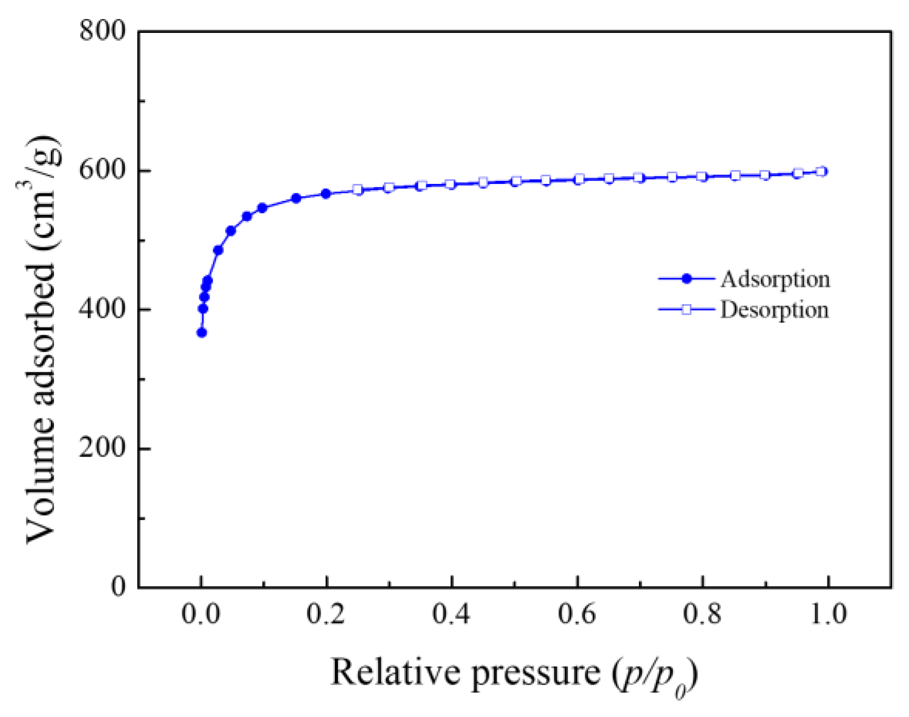
The nitrogen adsorption isotherm of MSP20 is presented in
Figure 2. A steep increase in the adsorbed volume at P/P
0 < 0.1 indicates that MSP20 has a high proportion of micropores (pores with diameters less than 2 nm). According to the BET analysis, the specific surface area of MSP20 was measured to be 2182.652 m
2/g.
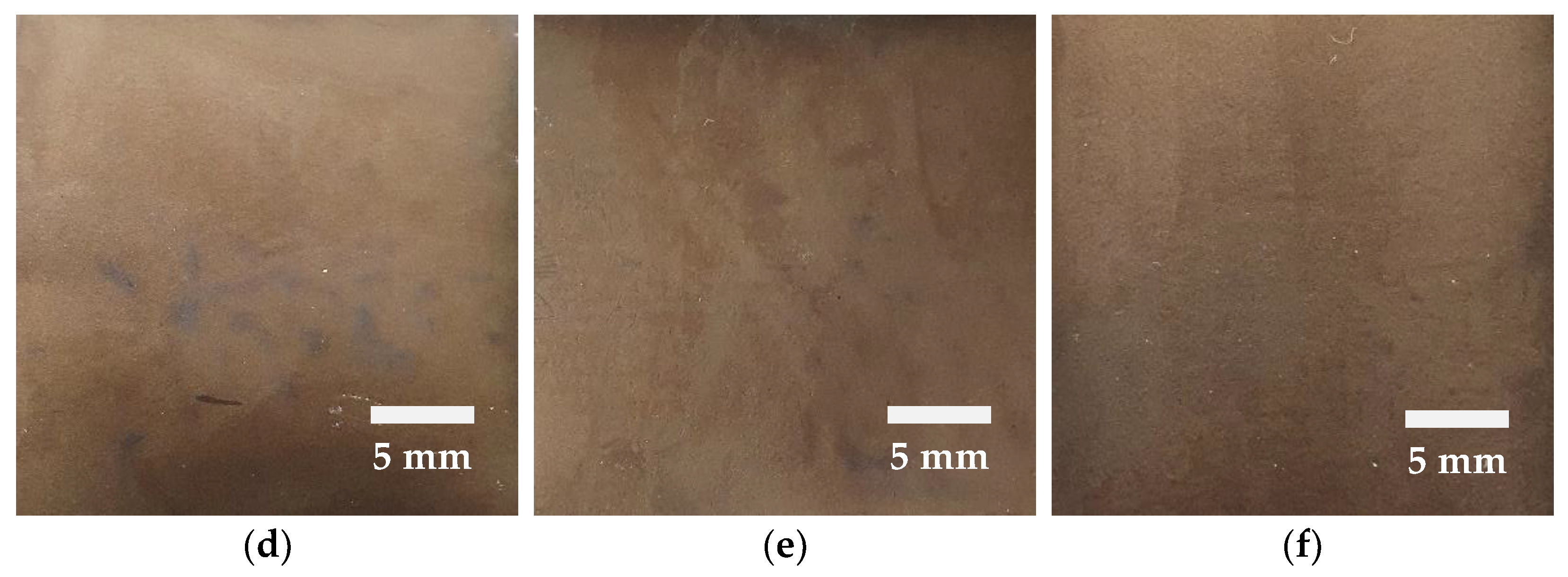
The changes in the electrode surface during the direct-contact prelithiation process using Li foil are illustrated in
Figure 3. As the contact time with the lithium foil increases, the surface of the electrode gradually changes color to a golden yellow, which can be observed during the process. Initially, uneven regions were observed on the soft carbon electrode. However, as time progressed, these uneven regions diminished, and uniformity was achieved across the entire electrode surface after 24 h. This phenomenon is likely attributed to the preferential insertion of lithium metal near the electrode surface. Lithium insertion preferentially occurs at the electrode surface due to diffusion, as the surface is in direct contact with the electrolyte and lithium foil. The prelithiation time varies depending on the amount and form of lithium applied when the lithium source is provided in the form of powder, strip, or foil [
39]. J. Yan et al. demonstrated uniform prelithiation within 2 h by employing a direct-contact prelithiation process with a lithium foil of a 15–20 μm thickness [
46]. This result was achieved using ultrathin lithium foil. In this study, lithium foil with a thickness of 100 μm was utilized, and we inferred that the prelithiation time may vary depending on the composition of the electrode and electrolyte. Visual inspection of the electrode surface stability revealed no cracking during the punching process after completing the prelithiation. Additionally, no surface cracking was observed even when the electrolyte dried and the surface became dry. These observations confirm that the surface stability was maintained even after the prelithiation process. Following the direct-contact prelithiation process using Li foil, ICP-OES analysis confirmed that the Li-ion concentration in the electrode reached 34,813 ppm after 24 h. The analytical results are summarized in
Table 2.
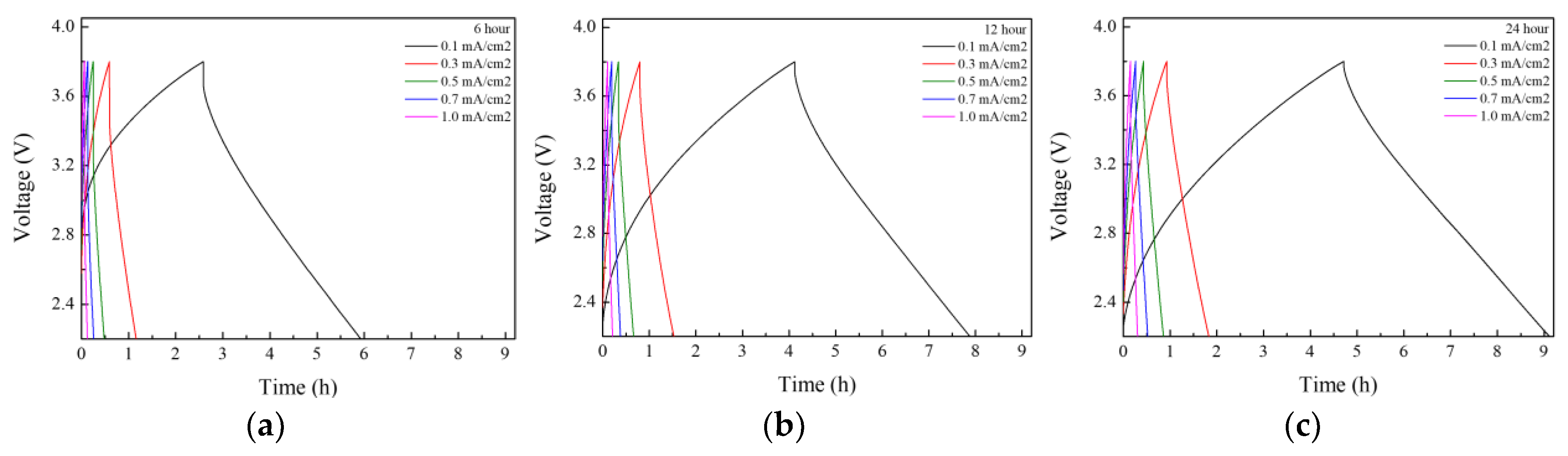
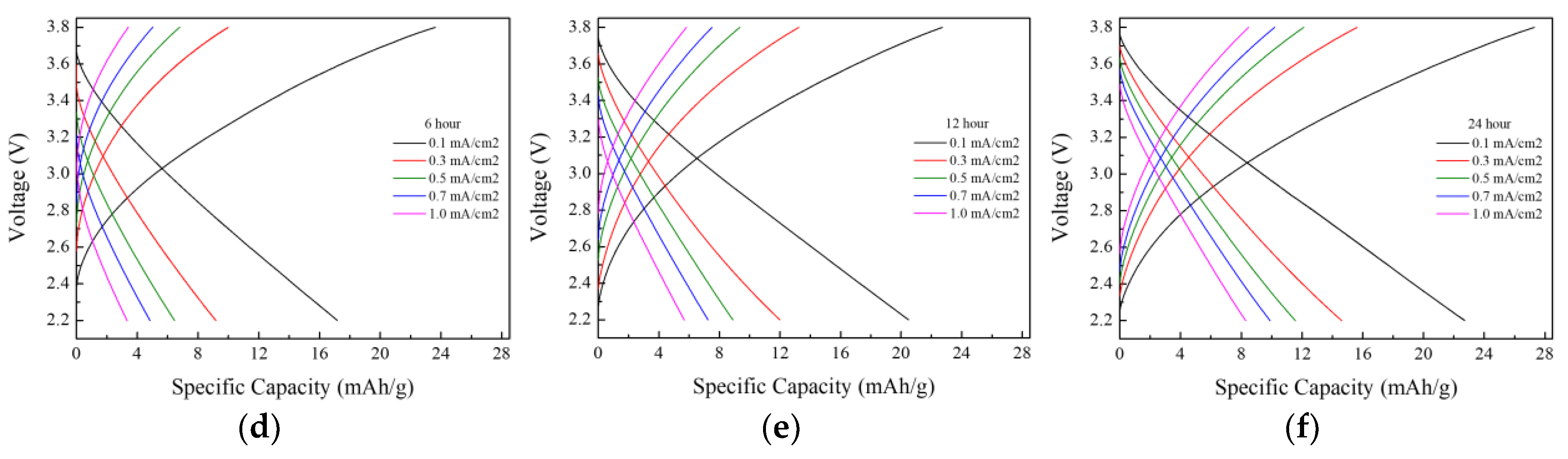
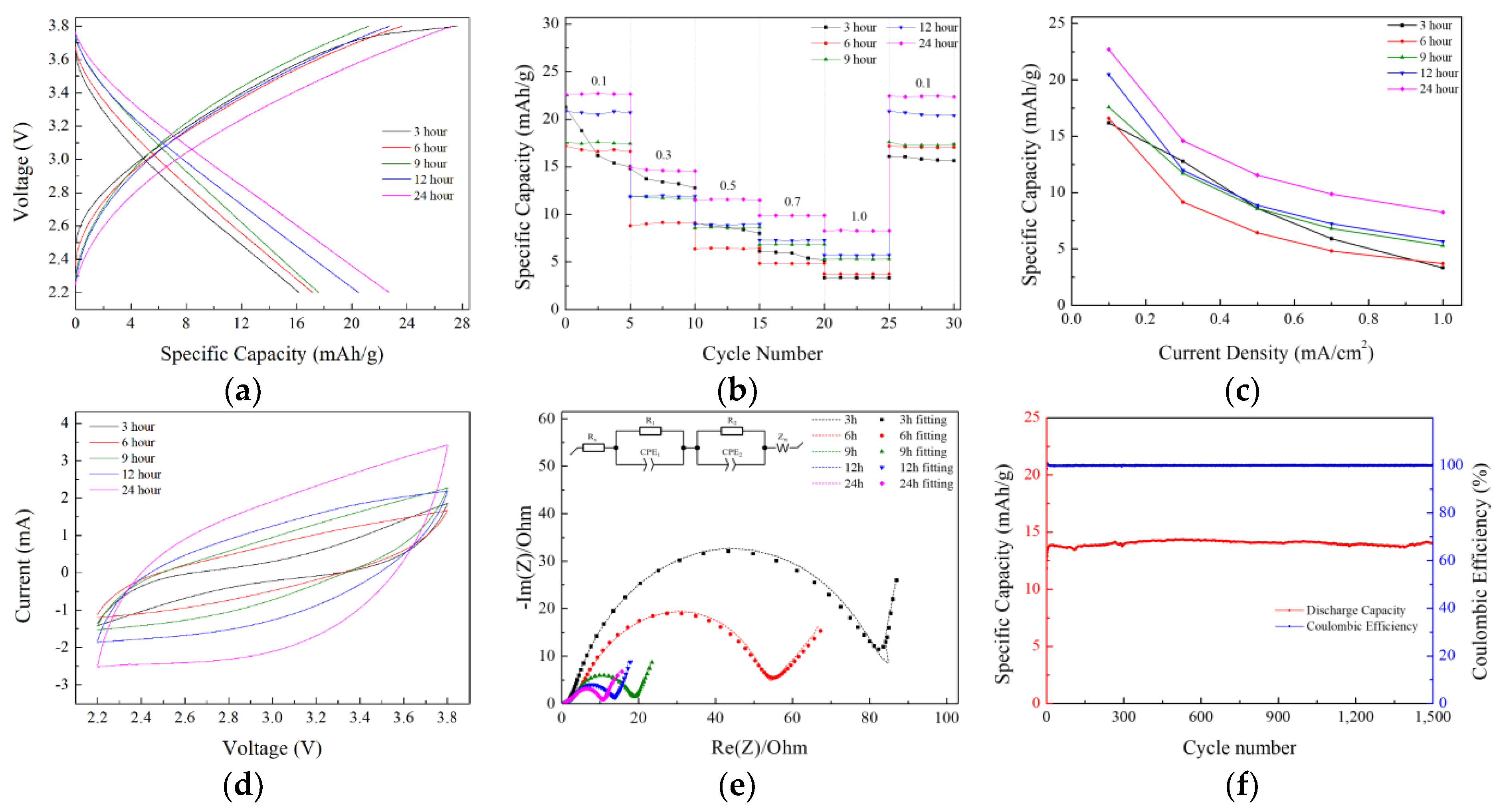
The electrochemical properties of the lithium-ion capacitors were evaluated after performing direct-contact prelithiation for 3, 6, 9, 12, and 24 h, and the results are presented in
Figure 4 and
Figure 5. The charge–discharge capacity measurements revealed a consistent increase in capacity with longer prelithiation durations. At a current density of 0.1 mA/cm
2, the highest capacity of 22.7 mAh g
−1 was observed in the LIC prelithiated for 24 h. The initial coulombic efficiency (ICE) and the coulombic efficiency at the 11th cycle after 10 charge–discharge cycles for prelithiation times of 3, 6, 9, 12, and 24 h are presented in
Table 3. The initial coulombic efficiency was the highest in the LIC prelithiated for 12 h, but the coulombic efficiency at the 11th cycle increased with longer prelithiation times, reaching the highest value in the LIC prelithiated for 24 h. Rate performance tests were conducted at current densities of 0.1, 0.3, 0.5, 0.7, and 1 mA cm
−2. The results showed a significant decrease in capacity with the increasing current density. This is attributed to the use of a three-electrode-cell setup for the experiments. It was anticipated that the application of this method to coin cells or pouch cells would result in a smaller capacity decrease. The long-term cycling performance and coulombic efficiency of the LIC prelithiated for 24 h were evaluated by charge–discharge cycling at a current density of 0.5 mA/cm
2 for 1500 cycles. After 1500 cycles, the capacity retention was approximately 98%, and the Coulombic efficiency was 99%.
The increase in the electrode’s specific capacity was also confirmed in the CV measurement results. When the voltage range and scan rate are the same, an increase in the internal area of the CV curve indicates a corresponding increase in the capacity of the LIC. The internal area of the CV graph expanded as the prelithiation time increased, with the 24 h doped sample exhibiting the highest capacity. Furthermore, the absence of oxidation/reduction peaks and the rectangular-like shape observed in the CV curve indicate that energy was stored and released through the formation of an electric double layer.
To evaluate the effects of prelithiation on the polarization resistance and reaction kinetics, the EIS (electrochemical impedance spectroscopy) spectra of lithium-ion capacitor cells were measured in the frequency range of 10 mHz to 1 MHz with a sinusoidal signal amplitude of 10 mV. As shown in
Figure 5e, the Nyquist plots corresponding to different prelithiation durations exhibit similar shapes, characterized by two semicircles in the high-frequency region and a straight line in the low-frequency region.
The intercept of the curve in the high-frequency region is attributed to the ohmic resistance (R
s). The first semicircle corresponds to the resistor/capacitor parallel combination (R
SEI/C
SEI), representing the migration of Li⁺ ions through the solid electrolyte interphase (SEI) film on the surfaces of carbonaceous materials. The second semicircle is associated with the charge transfer process, represented by the resistor/double-layer capacitor parallel combination (R
ct/C
dl). The straight line observed in the low-frequency region is ascribed to the Warburg impedance corresponding to the diffusion regime of Li ions through the electrode (Z
w). To analyze the EIS spectra, equivalent circuit modeling was performed to calculate the parameters of each component [
50].
Table 4 shows the parameters corresponding to each component. The equivalent circuit used for fitting is depicted within the EIS graph. It was observed that as the prelithiation time increased, the resistance associated with the SEI layer (R
1) and the charge transfer resistance (R
2) decreased. This phenomenon appears to be due to the initially non-uniform insertion of lithium during the early stages of prelithiation, which improved over time as the amount of lithium inserted into the anode increased, leading to enhanced doping uniformity. During this process, the lithium did not undergo metallization on the electrode surface.
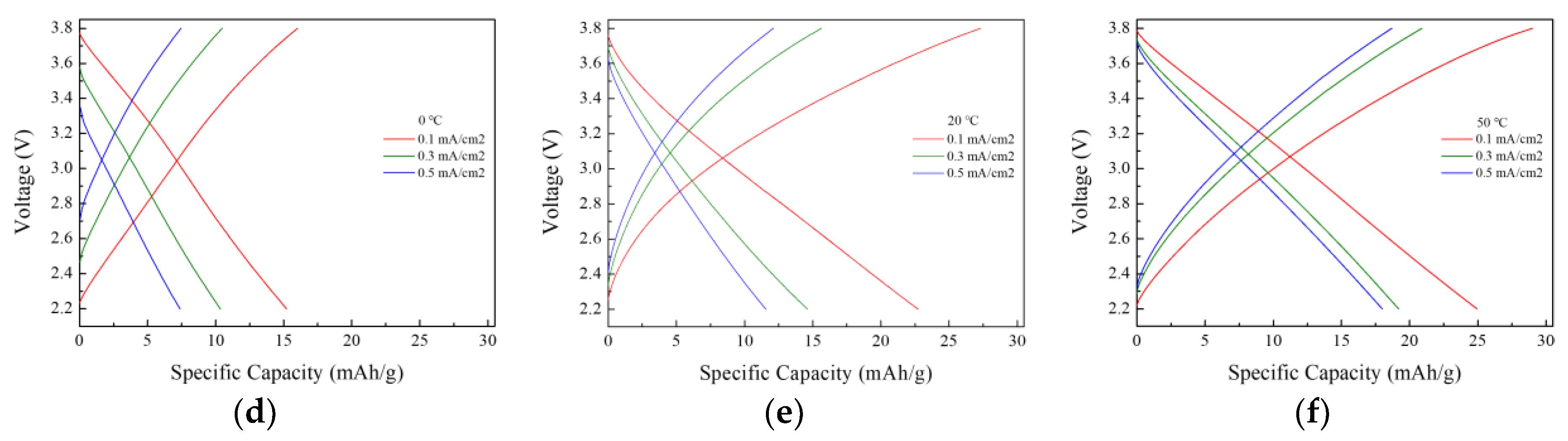
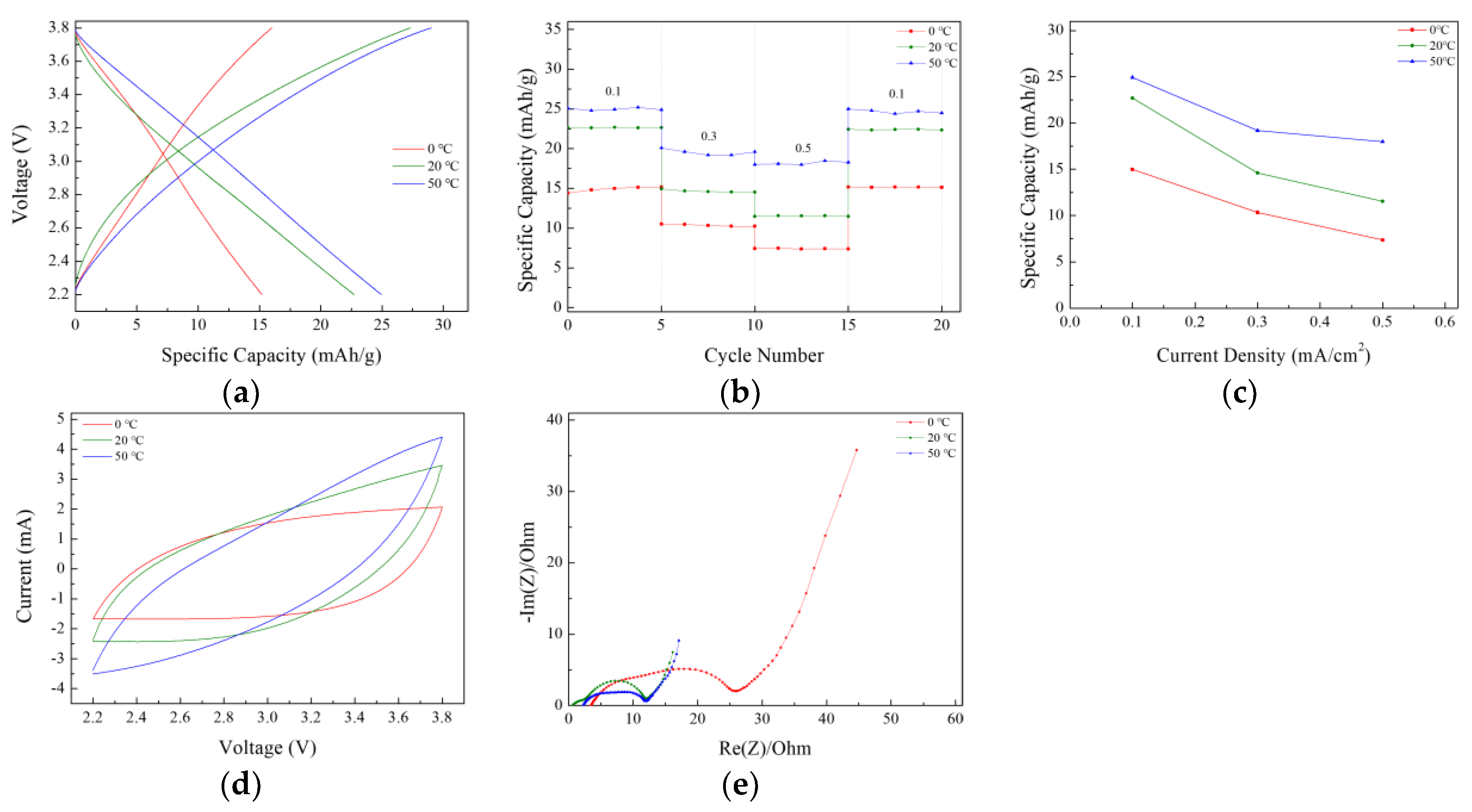
After 24 h of prelithiation at 50 °C and a current density of 0.1 mA/cm
2, a capacity of 24.9 mAh g
−1 was achieved, as shown in
Figure 6. The rate performance test results in
Figure 7 showed that the electrodes prelithiated at 50 °C exhibited slightly better capacity retention during high-rate discharge, and lower prelithiation temperatures also resulted in decreased capacity retention. A similar trend was observed in the CV and EIS measurements.
The decrease in the LIC capacity at lower temperatures is attributed to the reduced ionic conductivity and increased viscosity of the electrolyte.
Table 5 presents the ionic conductivity and viscosity of the electrolyte measured at 0 °C, 20 °C, and 50 °C, showing a trend where ionic conductivity decreases and viscosity increases as the temperature decreases. As the viscosity of the electrolyte increases, the mobility and diffusion rates of ions within the electrolyte decrease. Consequently, during the prelithiation process, the insertion rate of lithium ions slows down, potentially resulting in a lower amount of lithium intercalated into the anode compared to the other two temperature conditions. Insufficient lithium insertion leads to the continuous consumption of lithium from the electrolyte during repeated charge–discharge cycles, ultimately causing capacity degradation.
As the temperature increases, the migration of lithium ions is facilitated, which may favor the insertion of a larger amount of lithium into the electrode within the same duration. However, when applying direct-contact prelithiation at high temperatures, it is necessary to maintain conditions within a temperature range that does not cause the degradation of the electrolyte. While higher temperatures in direct-contact prelithiation are expected to achieve higher capacities, extending the prelithiation time is anticipated to be a more effective approach.
To identify the composition of the solid electrolyte interphase (SEI) formed on the anode surface after direct-contact prelithiation at different temperatures, X-ray photoelectron spectroscopy (XPS) was employed to analyze the key elements and their chemical bonding states. The high-resolution Li 1s XPS spectra are presented in
Figure 8.
Quantitative analysis using XPS revealed that the lithium contents in electrodes prelithiated at 0 °C, 20 °C, and 50 °C were 27.9, 35.75, and 36.09 atom%, respectively, showing an increasing trend as the prelithiation temperature increased. In the Li 1s spectra, peaks associated with Li2O, LiOH, Li2CO3, and LiF were observed at approximately 53.7, 54.6, 55.2, and 55.7 eV, respectively. These chemical species are commonly found in SEI layers.
LiF is formed either through the decomposition of LiPF
6 in the electrolyte or through the reaction between thermodynamically unstable LiPF
6 salt and Li
2CO
3, which is generated from the reduction of EC solvent. LiF reduces the resistance of the solid electrolyte interphase (SEI), thereby improving the cycle performance of the cell. Li
2CO
3 is produced through the reduction of organic electrolyte solvents and serves as a thermodynamically stable component that suppresses continuous electrolyte decomposition and enhances SEI stability. During the prelithiation process, vacuum sealing was performed inside the glovebox to prevent exposure to external moisture. However, trace amounts of water in the electrolyte may still react with lithium ions to form Li
2O or LiOH, which can improve the stability and conductivity of the SEI. Solvents with high dielectric constants and viscosities, such as ethylene carbonate (EC), increase the ionization of salts like LiPF
6 and promote reduction reactions, leading to subsequent reactions with water to form Li
2O or LiOH. In EC/DEC mixed electrolytes, Li
2O is commonly formed, whereas in EC/DMC mixed electrolytes, LiOH is predominantly generated [
51,
52,
53].
As the prelithiation temperature increased, the peak areas of LiF, LiOH, and Li2O increased, while Li2CO3 also showed a slight increase. The increase in the peaks of inorganic species at higher temperatures indicates that, given the same duration, a higher temperature facilitates more stable SEI formation and increased lithium insertion, which can lead to an enhanced electrochemical performance.
Electrochemical prelithiation was performed at 20 °C using constant-current discharge at a current density of 20 mA g
−1 until reaching 0.002 V. Lithium-ion capacitors were then assembled, and their performances were evaluated and compared, as presented in
Figure 9. The electrochemical prelithiation under these conditions required approximately 12.5 h. Anodes were prepared using the electrochemical prelithiation method, and lithium-ion capacitors were assembled for electrochemical testing. At a current density of 0.1 mA/cm
2, the specific capacity measured based on the third cycle was 37.3 mAh g
−1, which is higher than that achieved with the direct-contact doping method after 24 h of prelithiation. The rate performance test results showed that LICs using the direct-contact doping method exhibited relatively significant decreases in their specific capacities as the current density increased, whereas LICs employing the electrochemical doping method demonstrated smaller reductions in their specific capacities. The CV and EIS results also revealed similar trends, suggesting that electrochemical prelithiation is a more effective method. The reason why LICs using the direct-contact method exhibit a lower performance than those using the electrochemical method appears to be the non-uniform lithium insertion. The electrochemical prelithiation method inserts lithium into the electrode through an electrochemical reaction, allowing for uniform lithium insertion across the entire electrode and enabling stable SEI formation. However, direct-contact prelithiation relies on the physical contact between the lithium and the electrode for lithium insertion, making it difficult to achieve uniform lithium insertion. As a result, lithium may be excessively or insufficiently inserted in specific regions of the electrode. Non-uniform lithium insertion is a factor that degrades the performance of the cell [
42].
The performances of LICs with direct-contact prelithiation were compared with previous studies, and the results are presented in
Table 6. The current density and specific capacitance values from previous studies were calculated based on the reported current, electrode area, and average active mass or cell mass of the electrodes. In this study, when a 100 μm thick lithium foil was used, the LIC prelithiated at 20 °C for 24 h exhibited a relatively lower specific capacitance compared to previous studies that utilized ultrathin lithium. However, the LIC prelithiated at 50 °C for 24 h demonstrated a specific capacitance comparable to that of LICs using ultrathin lithium.


