Review

Reducing Rare-Earth Magnet Reliance in Modern Traction Electric Machines

by
Oliver Mitchell Lee
and
Mohammadali Abbasian
*
Warwick Manufacturing Group, University of Warwick, Coventry CV4 7AL, UK
*
Author to whom correspondence should be addressed.
Energies 2025, 18(9), 2274; https://doi.org/10.3390/en18092274
Submission received: 29 March 2025 / Revised: 17 April 2025 / Accepted: 25 April 2025 / Published: 29 April 2025

Abstract

Currently, electric machines predominantly rely on costly rare-earth NdFeB magnets, which pose both economic and environmental challenges due to rising demand. This research explores recent advancements in machine topologies and magnetic materials to identify and assess promising solutions to this issue. The study investigates two alternative machine topologies to the conventional permanent magnet synchronous machine (PMSM): the permanent magnet-assisted synchronous reluctance machine (PMaSynRM), which reduces magnet usage, and the wound-field synchronous machine (WFSM), which eliminates magnets entirely. Additionally, the potential of ferrite and recycled NdFeB magnets as substitutes for primary NdFeB magnets is evaluated. Through detailed simulations, the study compares the performance and cost-effectiveness of these solutions against a reference permanent magnet synchronous machine (PMSM). Given their promising performance characteristics and potential to reduce or eliminate the use of rare-earth materials in next-generation electric machines, it is recommended that future research should focus on novel topologies like hybrid-excitation, axial-flux, and switched reluctance machines with an emphasis on manufacturability and also novel magnetic materials such as FeN and MnBi that are currently seeing synthesis challenges.

1. Introduction

This research delves into the latest advancements into electric machines (EM) and magnet materials that reduce or eliminate rare-earth (RE) permanent magnet (PM) use through an exploration of magnet-free and magnet-assisted machine topologies. Neodymium–iron–boron (Nd2Fe14B) magnets are highly valued for their unmatched magnetic strength in traction machines, although their high cost and reliance on China’s market dominance introduce geopolitical and economic risks [1,2]. Their price volatility is evident in significant 2012 and 2022 spikes, illustrated in Figure 1. Thus, there is a need to explore alternative solutions to ensure a future for high power density EMs and electric vehicles.
Electric machines play a pivotal role in the transition toward sustainable transportation, offering significantly higher efficiency at approximately three times greater than internal combustion engines (ICEs). As the electrification of the automotive sector accelerates, it directly addresses a critical source of emissions, with transportation contributing nearly half of global CO2 output [3]. ICEs are not only inefficient but are also major emitters of harmful pollutants. In the EU alone, fine particulate matter from ICE exhaust is linked to over 300,000 premature deaths annually [4]. In addition to CO2, ICEs emit methane and nitrous oxides—greenhouse gases (GHGs) with much higher global warming potential, further exacerbating climate change and harming respiratory health. The urgency of this transition is underscored by the ongoing climate crisis: global temperatures have already risen by 1 to 1.5 °C above pre-industrial levels [5], with projections indicating continued warming that threatens ecosystems and biodiversity worldwide. Electrification, therefore, is not just a technological upgrade, it is a crucial strategy for reducing both tailpipe and lifecycle GHG emissions, helping to slow the accumulation of atmospheric GHGs and therefore slow global warming.
Figure 1. Neodymium compound commodity price from 2010 to 2025, with data from [6].
Energies 18 02274 g001
However, this growing push for electrification will significantly increase the demand for RE-PMs in EMs if hybrid and electric vehicles (HEVs and EVs) dominate new car sales in the near future. With the popularity of the SUV, their increased power needs will consume more RE materials [7]. Demand for traction machines is expected to grow over tenfold by 2030, with forecasts predicting up to 140 million EV machines annually by 2034, further strained by competing applications like wind turbines [8,9]. This heightened demand risks exponentially raising RE-PM costs and poses challenges for OEMs to secure a stable, diverse supply chain, with potential economic losses from supply disruptions. Additionally, RE material mining exacerbates environmental destruction, greenhouse gas emissions, and unsafe working conditions, threatening the sustainability of the automotive industry [10,11].
The purpose of this study is to investigate alternative magnetic materials as opposed to the expensive, cost-volatile, and environmentally harmful sintered NdFeB magnets, as well as the potential EM topologies that can address these challenges posed to the electrification industry. The research’s significance stems from its contribution to the broader goal of decarbonising the automotive industry as part of the global effort to combat climate change. This effort aims to evaluate specific hypotheses regarding the feasibility of these materials to replace or complement traditional RE-PMs and to assess their potential for reducing reliance on RE-materials while maintaining the efficiency and power density of contemporary traction machines.
This research addresses a knowledge gap by investigating the performance and viability of recycled NdFeB magnets in traction machines. While some studies, such as those by [12,13], have investigated recycled magnets versus virgin magnets, these have been limited to specific power levels, 385 W and 8.8 kW, respectively. Moreover, study [12] focused solely on the brushless DC motor, which is a topology not employed in electric vehicles. This EM will have a different magnetic circuit and therefore could yield different performance outcomes to those used in traction machines. In [13], the study focuses on a traction machine for an electric boat which will presumably be suited for low-speed, high-torque efficiency, and durability in marine environments with water cooling. In contrast, EMs in electric vehicles require high power output, compactness, and lightweight designs with advanced thermal management in the absence of a water surplus. This limited scope and large difference in relation to automotive traction machines leads to a substantial knowledge gap in the power range of 80–300 kW plus. There are also limited studies looking at a range of solutions, either in novel topologies or new magnet materials to reduce and/or eliminate RE magnet use. The outdated nature of much of the existing literature fails to incorporate recent technological developments and trends, such as the increasing adoption of wound-field synchronous machines (WFSMs) by major OEMs like BMW [14,15].
The main research aim is to explore industry-feasible alternative options to PMSMs by assessing reduced magnet or magnet-free machine topologies, completed via simulation and analysis of various machine topologies chosen by an exhaustive review of the available literature. Specific objectives include the evaluation of peak and continuous performance, efficiency maps, losses, efficiency over the WLTP class 3 duty cycle, thermal transient maps, torque ripple, and mechanical finite element analysis. Key performance metrics will include the performance-to-cost ratio, continuous performance, driving cycle efficiency, and loss breakdowns. A detailed cost analysis of various EMs will be conducted by integrating material price data and motor-specific inputs. A decision-making matrix will be developed to provide a clear and comprehensive framework for OEMs and EM researchers. This matrix will assist in selecting the optimal machine topology by evaluating factors such as cost–performance ratios, efficiency, demagnetisation resilience, and drivability, while also enabling cost-effective strategies to mitigate supply chain risks associated with RE materials and optimise production processes to prevent delays and financial losses.
The structure of this paper is organised as follows: it begins with a review of magnetic materials and alternative machine topologies, followed by a detailed description of the materials and methods, including data collection and simulation procedures. The subsequent sections present the simulation results and visualisations, a discussion addressing key findings, limitations, and a cost analysis, followed by practical recommendations. The paper concludes with a summary of the main findings and suggestions for future research directions.

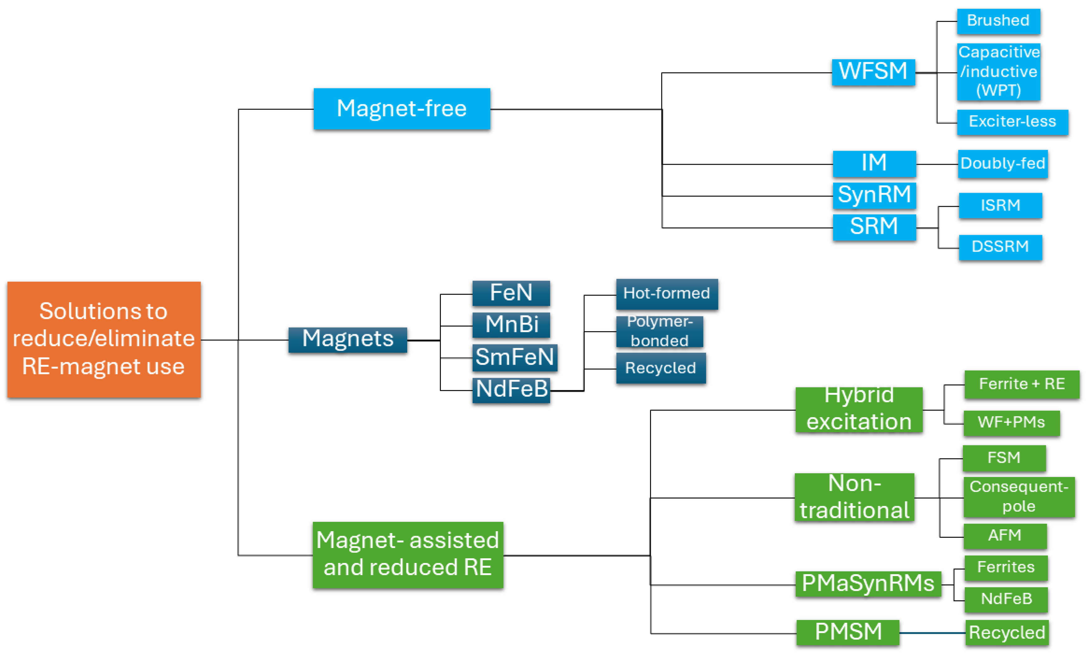
2. Review of Potential Magnetic Materials and Topological Solutions

Prior to the simulation effort, an exhaustive literature review was conducted on magnet-free and magnet-assisted/reduced topologies and solutions existing in industry and academia, shown in Figure 2. The PMSM was considered as the EM to rival.

2.1. Material Substitution Strategies

Key material strategies to diversify from sintered NdFeB include hot-formed, polymer-bonded, recycled NdFeB magnets, and researching alternative magnets like manganese bismuth (MnBi), samarium-iron-nitride (Sm2Fe17N3), and iron nitride (Fe16N2). These have significant potential despite the challenges in synthesis. MnBi magnets offer high-temperature coercivity and moderate performance but have a low/moderate BHmax and require new manufacturing processes, limiting their viability [16,17]. Fe16N2 magnets promise exceptionally high theoretical magnetic strength but are hindered by low coercivity, synthesis difficulties, and phase instability [18,19]. Sm2Fe17N3 combines the advantages of samarium with abundant iron and nitrogen, yields better demagnetisation resilience at very high temperatures and has better corrosive resistance than sintered NdFeB, yet faces thermal stability issues during manufacturing despite its enhanced magnetic properties [17].
Sintered magnets, while offering high BHmax values, are limited by intellectual property restrictions, high alloy waste, and the need for heavy RE elements like dysprosium and terbium. Alternatives like polymer-bonded and hot-formed magnets present promising avenues for cost reduction and decreased RE dependence [11,20]. Polymer-bonded magnets, made by mixing NdFeB alloy powder with a polymer binder, are isotropic and cost-effective but face concerns about recyclability and lower magnetic performance, whereas hot-formed magnets, which produce smaller grains and avoid heavy RE elements, have been used by OEMs like Honda for their HEVs [21,22,23].
Recycling NdFeB magnets through methods like hydrogen decrepitation (HD) and melt-spinning is claimed to recover up to 95% of virgin materials, with modest reductions in magnetic properties and an increase in coercivity after recycling [24]. A key advantage of HD is its ability to break down magnets into powder without the need for disassembly, which is often a challenge in traditional recycling methods, where magnets are difficult to remove from rotors [25]. However, the process requires high temperatures and precise hydrogen control, leading to substantial energy consumption and potential variability in the quality of the recycled material. Furthermore, current recycling processes remain economically uncertain and face challenges due to disassembly of end-of-life products [24,26,27]. Table 1 summarises the key advantages and disadvantages of the discussed alternative magnet materials in terms of their magnetic properties and practical considerations.

2.2. Topological Substitution Strategies

Magnet-free machines utilise alternative excitation methods instead of permanent magnets (PMs), with types including induction machines (IMs), wound-field synchronous machines (WFSMs), synchronous reluctance machines (SynRMs), and switched reluctance machines (SRMs). Although these machines generally offer lower efficiency and torque density, advances are improving their performance, making them more cost-effective and less vulnerable to price fluctuations. IMs are a well-established technology that are self-starting with low maintenance, reliable operation, and cost-effectiveness, especially at partial loads. However, they suffer from lower power density and power factor, and require complex control methods which has led to a decline in their market share for electric vehicles, in favour of PMSMs. Alternative IM topologies, such as the doubly-fed induction motor, have found success in wind turbines but struggle to meet EV power density and efficiency requirements [28,29,30,31,32].
SynRMs generate high reluctance torque through multiple flux barriers and the absence of PMs means the machine is low cost, has low torque ripple, and relatively high efficiency. However, they suffer from a narrow constant power speed range (CPSR), low power factor, and poor torque density, with increased flux barriers weakening the structure, often necessitating tangential ribs for stress resistance [33]. SRMs on the other hand, have good efficiency and fault tolerance but face significant challenges with noise, vibration, and harshness (NVH) due to high torque ripple. Despite successful scaling efforts in older models like the 2003 Toyota Prius, SRMs require specialised drives and more advanced control methods to mitigate torque ripple, limiting their mass-market appeal [34,35,36]. Recent SRM innovations include multi-stack architectures to reduce torque ripple and segmental rotors for improved torque density and efficiency. However, these designs remain mechanically weak or require complex assembly, raising doubts about their readiness for the mass market [37,38,39]. Another novel hybrid machine combining IM and SRM principles shows promise with high torque density and efficiency but exhibits torque ripple at low loads, limiting its potential for traction applications without further development [40].
WFSMs are widely used in power generators and have recently been adopted by OEMs like BMW and Renault for EV applications due to their high fault tolerance, power, and torque density at a relatively low cost. However, efficiency is modest at low/medium speeds, and they suffer from high copper losses due to the resistance in the windings of both the rotor and stator when there is a current flowing, limiting their efficiency and torque density compared to PMSMs. In contrast to traditional EMs where rotor excitation is achieved with embedded magnets, the WFSM achieves excitation via field windings in the rotor. This offers high field-weakening control and a wide CPSR. However, they require complex excitation methods, such as brushes or wireless power transfer (WPT) methods, both of which introduce challenges like wear and cooling issues [14,41]. Research into novel WPT techniques, including inductive and capacitive systems, has shown promising improvements in efficiency and power transfer, with some systems achieving comparable performance to brushed methods [42,43,44]. However, WPT introduces increased complexity, mass, and cost. An alternative approach of exciter-less systems integrated directly within the stator has been explored, but high torque ripple and magnetic loading issues have prevented this from meeting traction performance requirements [45]. The comparison of various excitation methods remains ambiguous, with some studies favouring inductive methods over capacitive solutions [46].
Permanent magnet-assisted synchronous reluctance machines (PMaSynRMs) are distinguished from the more traditional PMSM by their greater reluctance torque versus magnetic alignment torque, allowing them to use fewer PMs. The reluctance torque is generated from the inductance difference between the direct and quadrature axes, created by air cavities or flux barriers which would otherwise be filled with magnets in a PMSM. Designs in the literature [47,48,49] tend to use larger magnets in the innermost flux barrier, diminishing in size in each flux barrier toward the air gap for demagnetisation and mechanical resilience [50]. While they offer higher torque density and power factor than SynRMs, they cannot match the performance of PMSMs [51]. They are, however, still a step in the right direction.
Alternative machine designs include consequent-pole machines (CPMs) and axial flux machines (AFMs). CPMs use induced poles formed in the lamination rather than separate magnets or windings, reducing the amount of PM material used while maintaining nearly equivalent torque [52]. Research on CPMs has shown that shaping the PM and iron poles is crucial to mitigate harmonics and reduce torque ripple, although weakly induced poles remain a concern [53]. However, the lack of traction-scaled studies limits the clarity of this solution. AFMs are known for high torque, power density, efficient use of active material, and their flat and compact ‘pancake’ structure compared to PMSMs [54,55]. However, high cogging torque is a commonly cited issue. Although the potential to reduce PM usage in these machines remains uncertain in the literature, applying the SRM principle could eliminate the need for PM, but a performance comparison with conventional AFMs is still lacking [56].
A promising development in EMs is the use of both RE and ferrite (RE-free) magnets to generate torque, known as hybrid excitation (HE), reducing the reliance on RE magnets. These systems can be configured in series, parallel, or combined HE setups [50,57], with the parallel magnetic circuit typically offering the best torque density and demagnetisation resilience. However, the performance of such designs compared to state-of-the-art machines remains unclear, and practical challenges in manufacturing, such as the magnetisation processes of different magnet grades, limit their implementation [58]. Recent studies have also explored hybrid excitation wound-field synchronous machines (HE-WFSMs), combining RE-PMs and a wound field in the rotor. These machines offer enhanced efficiency and torque density, but they also suffer from higher torque ripple and heat management issues [59]. One example achieved a 39% increase in maximum torque and a 4% improvement in efficiency but complexity in mass production is a likely roadblock [15]. Another topology, the flux-switching machine (FSM) has both the winding and PMs in the stator. It operates by dynamically switching the magnetic flux path between the stator windings and PMs. High efficiency, torque density, and a wide CPSR come alongside a lower power factor [60]. Whilst the rotor design is simpler, the stator complexity is higher. Therefore, the control of these machines is highly complicated and research is limited. Table 2 summarises the key advantages and disadvantages of the discussed alternative machine topologies in terms of their performance and practical considerations.

3. Materials and Methods

Methods for Data Collection

This research employed the use of Ansys Motor-CAD version 2023.2.2. This was chosen for data collection due to its established use in machine simulation for mid-level design, employing analytical methods and 2D finite element analysis [61,62], and its results have been validated in experimental studies [43,61,63,64]. Secondary data were obtained from a previous experimental study on NdFeB magnet recycling [26], in which the percentage change in key magnetic properties, such as remanence, coercivity, and energy product, was calculated between scrap NdFeB magnets and the product after the first recycling stage. These percentage changes were then mathematically applied to a primary N45UH grade magnet [65] in order to simulate the magnetic performance of a corresponding recycled variant, denoted as recycled N45UH in Table 3. The primary N38UH [66] is shown alongside to illustrate the similar critical magnetic properties.
The simulated EMs are shown in Figure 3 and are predominantly based on the accessible EM templates in Ansys Motor-CAD 2023.2.2. The machine template ‘e10’ is used for the baseline PMSM; ‘e3’ is used for the WFSM; and because no high saliency EM exists in the template library, the PMaSynRM used a design in the literature. Specifically, a design of similar visage to ‘Model 6’ (different geometries) in [48] was chosen for the PMaSynRM adopted in this study. This design has five total flux barriers and four homogenised magnets in the innermost layers. This design was chosen because it had low magnet usage which better fulfilled the research aim. The manual build was assumed to have very similar dimensions and therefore performance to this machine. Typically, SynRM/PMaSynRMs are found in four pole setups. However, for the comparison between the machine variations, the slot-pole combination must be the same between all machines (48s8p). This slot-pole configuration was in part chosen due to the existing template setups in Motor-CAD but also for the fact that it appears most commonly in traction machines in the last decade [31].
The baseline model was assumed to represent PMSMs used recently in the industry. Specifically, the magnet layout used in the ‘e10’ template adopts magnet shapes reported to be optimal for traction EMs [67,68,69]. For the WFSM, it was assumed that the machine was brushless, utilising a WPT system which excluded potential losses, inertia, or energy consumption associated with WPT. This was justified because experimental studies had compared the performance of brushed and brushless systems and found negligible differences [70].
All simulation settings were endeavoured to be the same to provide a robust comparison. Reproducibility is ensured by the provision of the main simulation and model settings in Appendix A. Hence, apart from differences concomitant to topology, the stator lamination diameter, stator bore, and air gap were all the same. In a similar way to [71], only the axial length changed to meet the peak torque requirements. In this effort, all machines used the same winding pattern/setup: hairpin windings with 6 layers, 2 parallel paths, and a coil throw of 6 with copper hairpin dimensions the same throughout. Additionally, all machines used NO18-1160 electrical steel for the rotor and stator laminations, Stahl 37 for the shaft, and N45UH/recycled/ferrite magnets for the concerning machines. In the calculation settings, all machines used a DC bus voltage of 400 V, 550 A RMS current, and 12,000 maximum rpm.
For continuous performance, all machines adopted the same spray-cooled cooling system and nozzle setup using ATF at an inlet temperature of 60 °C and 6 L/min. The spray cooling aimed to provide an equal distribution of ATF to the different machine components as shown in Figure A3 in the Appendix A.1. The nozzles were user-defined, 1 mm in diameter, and had a flow ratio of 1, with the internal flow ratio set to 0. Out of the 6 winding layers, the inner and outer end winding of layers a, c, d, and f were cooled, both front and rear. The rotor poles, front and rear, were also cooled. This setup meant that the local fluid velocity on all target surfaces was 7.088 m/s. Thermal performance was assessed with limitations on the winding and magnet temperature hotspots, at 180 and 160 °C, respectively.
For the motors with PMs, skew was employed in the rotor in three segments of 2.8125°. For the WFSM, skew was non-segmental. Hence, the total skew in the rotor was set to 5.625° to match the PM motors. For all simulations, an iron loss build factor of 1.5 was applied. This factor was assumed to adequately capture most of the detrimental effects that manufacturing would have on the magnetic properties of electrical steel [72]. Once all variables were the same, the machines were scaled to achieve 400 Nm peak torque. After the key performance data was extracted from each machine, ferrite and recycled magnets were inserted for the PM machines, axially scaled to meet the 400 Nm peak torque, and all simulations were repeated.
Given that the control method options in Motor-CAD were different for the WFSM and the PM machines, it was assumed that the maximum torque per ampere (MTPA) control for the PM motors provided comparable performance, efficiency, and driveability to the ‘minimum total copper loss’ control strategy used for the WFSM. This assumption’s credibility is confirmed by [73]. Implications, therefore, yielded machine operation indicative of maximising performance and not necessarily efficiency.
For the analysis of the total machine performance, the integral of the torque–speed and power–speed graphs were calculated. For the calculation of machine cost and scrap, the concentric punching equations were used as outlined in [74]. This method accounts for electrical steel scrap generated during concentric punching, which minimises waste by nesting parts. Rotor scrap mass was calculated as the difference between the volume of a solid cylinder and the actual rotor mass from Motor-CAD. Stator scrap includes losses from the air gap, square cut-outs, and winding slots. By summing rotor and stator scrap, total material waste is estimated for which to subtract from the final machine cost.

4. Simulation Results

This section presents the simulation results for each topology variation and describes and interprets the findings to provide a performance comparison. Each subsection delves into a particular key performance indicator (KPI) wherein all performance can be compared to one another between the variations. The results, as follows, start with the headlining KPIs, leading to the most specific KPI: peak torque and power performances, continuous performance, efficiency, thermal performance, mechanical and NVH performance, and demagnetisation resilience.

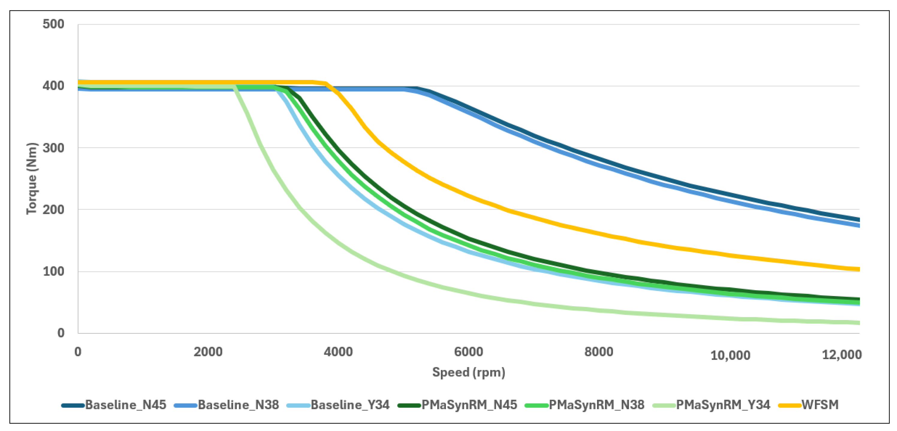
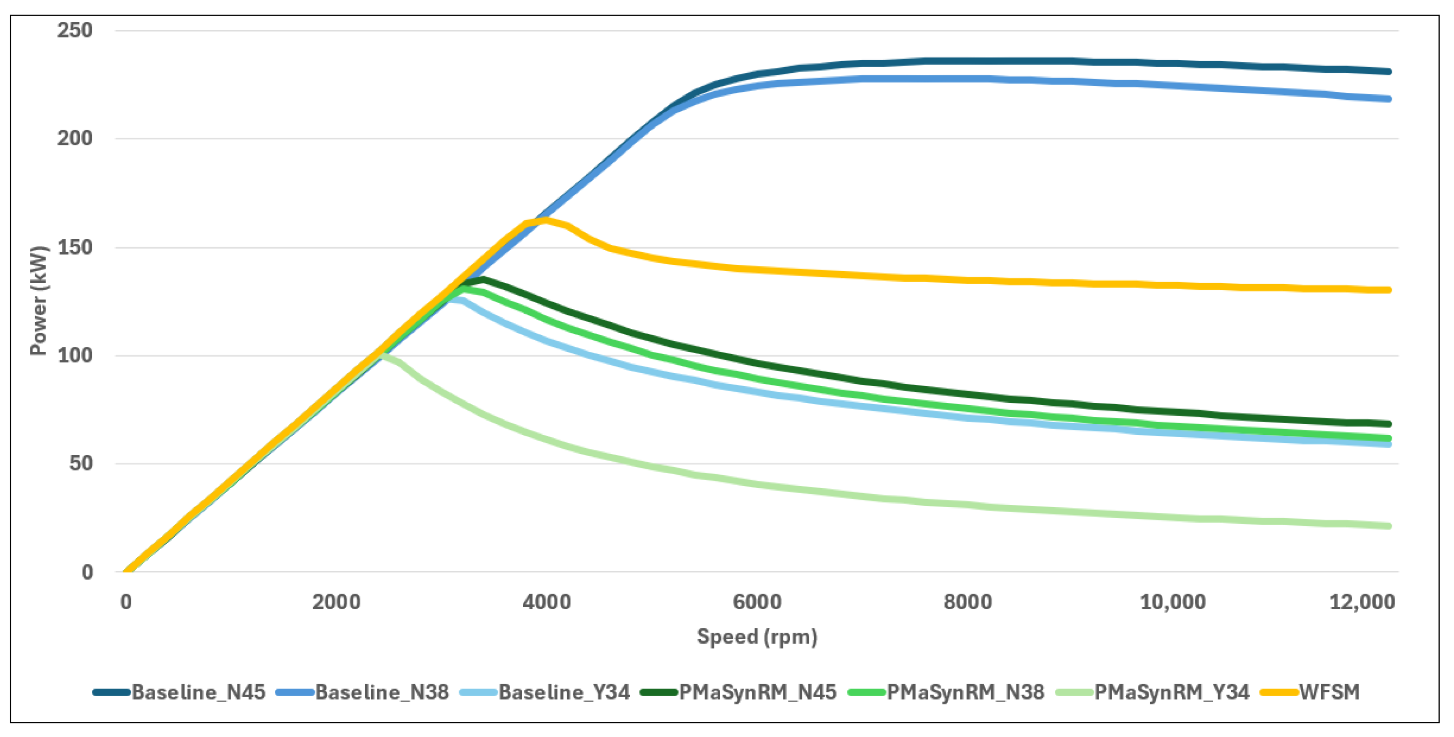
4.1. Peak Performance Envelopes

Figure 4 shows how each machine topology was scaled to approximately 400 Nm of torque. Due to axial length change only for scaling, the base speed between the machines is different. The baseline machine with NdFeB-based magnets experiences a shallower torque decline gradient in the flux-weakening region compared to the other machines. The baseline machine with recycled magnets required a 3.5% axial length increase, decreasing base speed slightly. The recycled magnets performed fractionally worse beyond the base speed. Substituting these for ferrite magnets, and a large decrease in base speed occurs due to an 82% longer axial length required. For the PMaSynRMs with NdFeB magnets, the base speed is significantly lower, around 3300 rpm, and the torque decreases rapidly as the rotational speed increases. Similarly, the addition of ferrites results in a reduction in base speed, with this machine experiencing the most pronounced torque decline in the flux-weakening region. Axial length compared to the primary magnet PMaSynRM was increased by 2.9% for the recycled magnets and 31% for the ferrite machine. The WFSM, with a base speed of approximately 3800 rpm, also shows a sharp torque decline but performs better than the PMaSynRMs across the entire operating range.
A wide CPSR in Figure 5 is exhibited for the baseline machines with NdFeB magnets, reaching a peak power of 236 kW and 228 kW, respectively. Only 126 kW peak power was reached with ferrite substitution. The WFSM experiences a peak power of 162 kW which quickly drops to below 150 kW, where it declines gradually. The PMaSynRMs with NdFeB magnets reach peak power at 135 kW and 131 kW, and the use of ferrites yields 102 kW. After their peaks, significant deterioration of the CPSR occurs.
Table 4 shows the mass, volume, and volumetric and gravimetric torque density for all machines, calculated from the peak torque divided by the active machine volume. The ‘B’ series denotes the baseline machines and ‘P’ for the PMaSynRM machines. As expected, the baseline PMSM machines with the NdFeB magnets are the most torque-dense at 11.5 Nm/kg and 11.1 Nm/kg due to their much shorter axial length and stronger magnets. The PMaSynRM with ferrites has the lowest torque density, due to a much greater axial length and moderate peak torque. The same order is apparent in volumetric torque density.

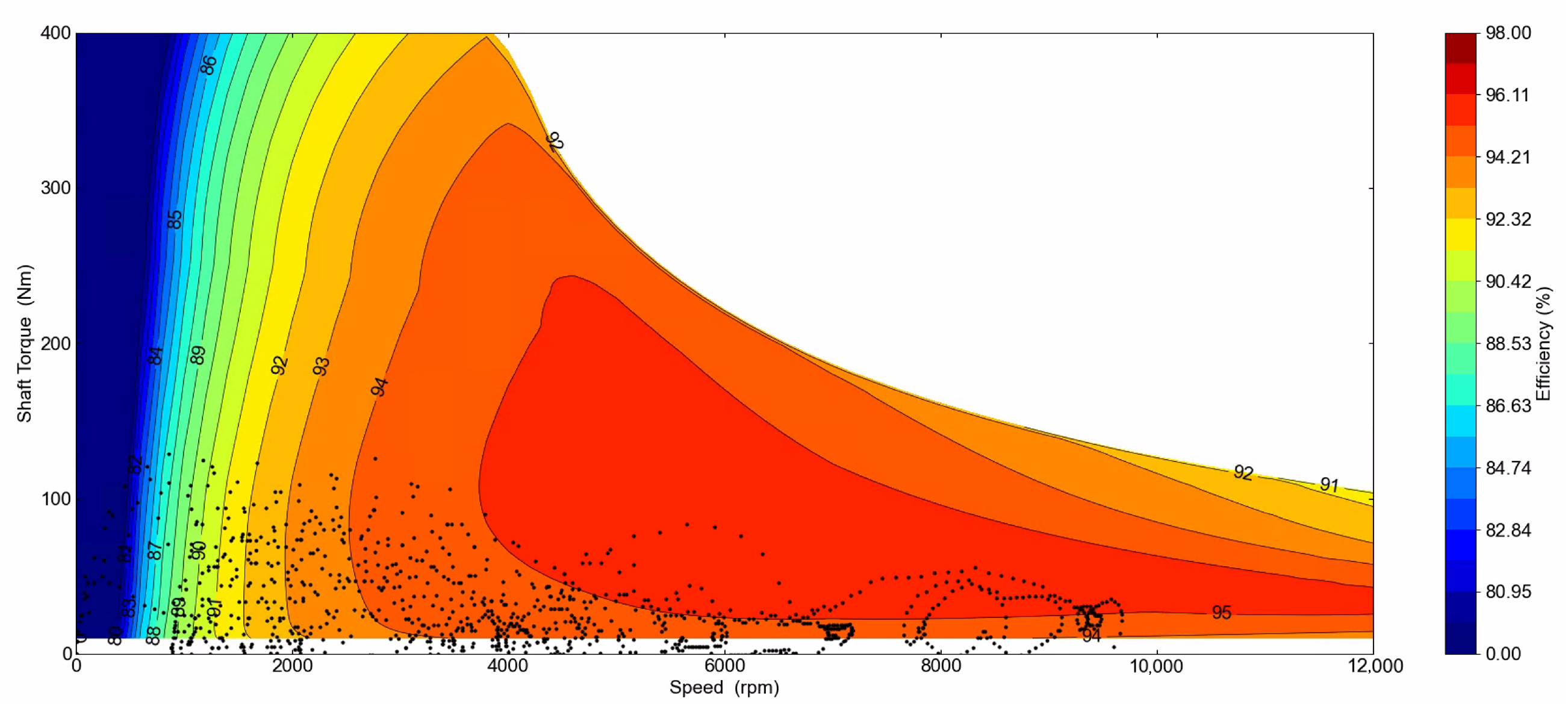
4.2. Efficiency Performance Envelopes

The WFSM demonstrated the highest total losses among the machines in Figure 6. Conversely, the PMaSynRM with primary magnets emerged as the most efficient machine, followed closely by its secondary magnet counterpart and the base machine with ferrites. An intriguing observation is the contrasting performance trend between the PMaSynRM and the PMSM, in that the use of weaker magnets resulted in lower total losses for the baseline machines, but the opposite is true for the PMaSynRMs, especially with ferrites. However, it should be noted that it could not achieve the duty cycle requirements, therefore operating at its limits, which is typically less efficient for EMs [42,71].
When examining the major constituent losses, the copper losses were highest for the WFSM, closely followed by the ferrite PMaSynRM. For the WFSM, this is due to the combination of losses in both the hairpin winding and the rotor field-winding. For the ferrite machines, the low remanent magnetic flux likely meant that the windings were operating at higher current density in an attempt to produce the desired torque. In terms of iron losses, the PMSMs recorded the highest values, which significantly contributed to their overall loss levels. This high iron loss is likely due to saturation, exacerbated by the machine’s shorter axial length compared to the PMaSynRMs and WFSM. Substituting ferrites into this same topology led to the lowest iron losses.
Figure 7 shows the efficiency based on energy use and on the WLTP Class 3 drive cycle, illustrated by black points. The NdFeB PMaSynRMs and the base machine with ferrite PMs have the best efficiency in energy use with the base ferrite machine achieving the highest efficiency in the drive cycle. Despite the highest total losses and worst efficiency in energy use, the WFSM does not score the worst efficiency over the WLTP driver cycle. The difference between the energy use and drive cycle efficiency is much greater for the baseline machines using NdFeB magnets, which will be explored in the efficiency maps.
The efficiency maps for the machines are documented in the subsequence. The same efficiency scale, peaking at 98%, has been used for all efficiency maps for comparison. The baseline machine with N45UH magnets is shown in Figure 8. A large region of 97%+ efficiency (reaching 97.66%) is achieved between approximately 1000 rpm and 7000 rpm. However, a number of the drive cycle points lie in a low-efficiency zone at very low torque. This implies that if the peak torque were lower or the vehicle model was based upon a heavier vehicle, it would yield a higher efficiency in the drive cycle.
The efficiency maps for recycled magnet and ferrite magnet substitutions in the baseline machine are illustrated in Figure 9a,b. No discernible change occurs with the recycled magnets, but the ferrite magnets experience a drop in peak efficiency compared to the N45UH magnet machine. Interestingly, however, the drive cycle points are positioned favourably in the majority of its high-efficiency areas.
Despite achieving greater efficiency overall, the peaks for the PMaSynRMs are lower. Using the N45UH magnets, a 97.02% peak was obtained in the small 97% + efficiency region in Figure 10. Its ability for modest-high efficiency at low torque may be part of its efficiency success. Unlike the base machine, this machine can retain higher efficiency at high rotational speed, but at high torque within the base speed, it suffers more losses.
The efficiency maps for recycled magnet and ferrite magnet substitutions in the PMaSynRM are shown in Figure 11a,b. Again, the recycled magnet efficiency map is largely the same, but the ferrite magnet shows decreased peak efficiency and the drive cycle points clearly extend beyond the operating region.
The WFSM exhibits lower efficiency at low speeds in Figure 12. However, beyond 3500 rpm, it has a wide peak efficiency region with high torque up to 12,000 rpm. Though its peak efficiency is lower at 95.67%, it excels in the drive cycle due to its high-speed performance. The machine’s inability to produce torque below approximately 10 Nm is due to the constraint of not being able to set a minimum current of 0 RMS, as is possible with PM machines in the software.

4.3. Continuous Performance

Initially, due to the effectiveness of oil spray cooling, the NdFeB baseline machines are not thermally constrained, as illustrated in Figure 13. However, as rotational speed increases, so do the speed-dependent losses such as bearing friction and AC winding loss at high frequencies. Hence, these machines become thermally limited and experience a gradual decline in torque until the base speed, where the deterioration accelerates. The NdFeB PMaSynRMs mirror this behaviour but with a more pronounced decline in continuous torque. The base machine using secondary magnets outperforms the primary magnet machine at approximately 10,000 rpm, something not exhibited by the PMaSynRMs. The reason for this is not clear-cut and will be discussed in the next section. The WFSM exhibits the poorest continuous performance until reaching 4000 rpm and 6000 rpm. Beyond these points, the WFSM progressively surpasses all other machines, except the NdFeB baseline machines, but ultimately exceeds these as well beyond 11,000 rpm. Its relatively poor performance can be explained by looking at the thermal map in the subsequent section. Interestingly, the machines with ferrites have identical performance starting from around 350 Nm but diverge at their respective base speeds. The baseline machine with ferrites then perform similarly to the PMaSynRMs with NdFeB beyond 4000 rpm. The PMaSynRM with ferrites performs particularly poorly, failing to meet the demands of the WLTP drive cycle (red points) for points between 5500 rpm and 10,000 rpm.
The continuous power envelopes are illustrated in Figure 14 where the red circles illustrate the WLTP Class 3 drivecycle. Between all the machines using PMs, the performance is very close until around 2000 rpm, where it diverges. Clearly, the base machines with NdFeB set a precedent with a much greater continuous peak power at approximately 165–170 kW. Then, a discrepancy between the two is evident beyond 9000 rpm. The PMaSynRMs can only reach about 65% of the base machines’ peak power, but merit is shown in only a gradual decline in continuous power beyond base speed as opposed to a steep decline for the baseline machines. The WFSM shows almost no decline in this respect, but its power suffers at low speeds and can only supply approximately 95 kW continuously at its peak.

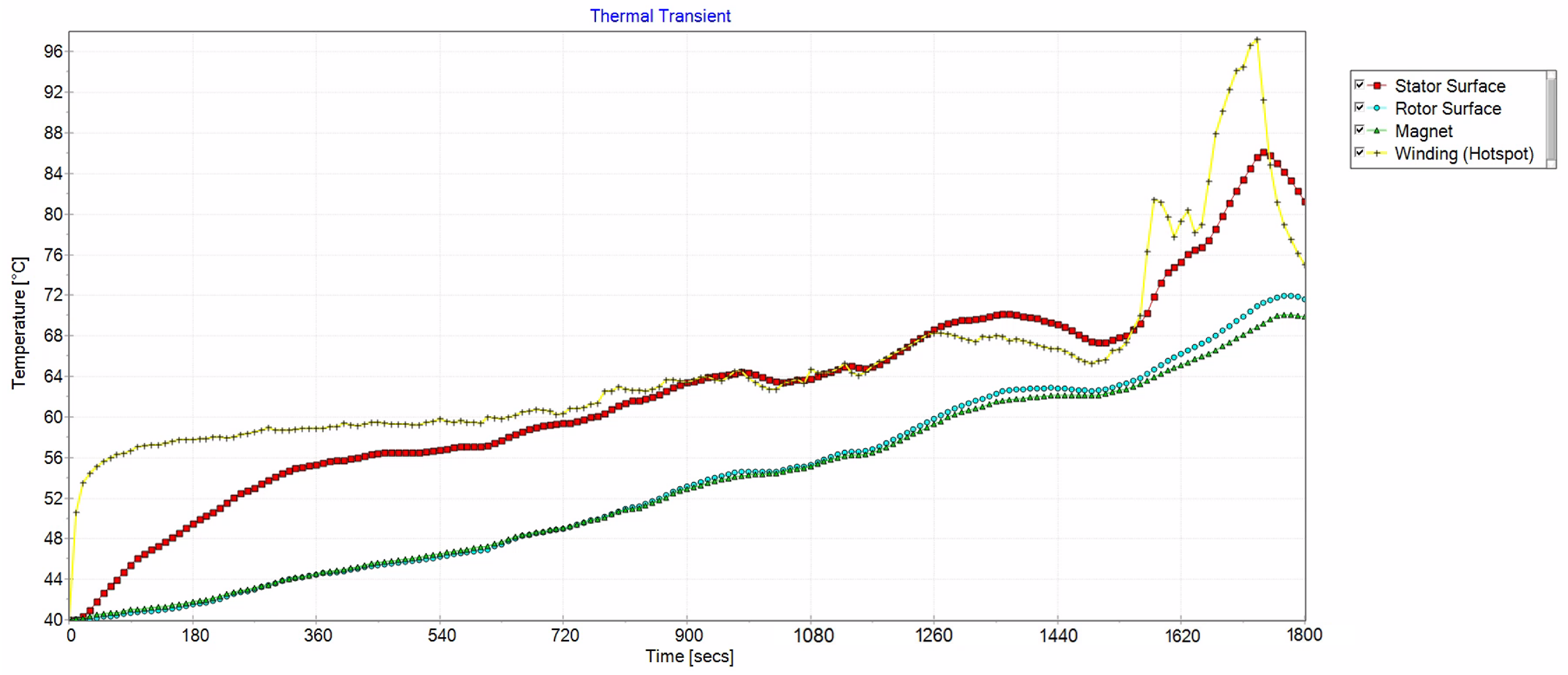
4.4. Thermal Performance

The thermal performance was simulated at 6000 rpm using steady-state simulations to model the temperature distribution, shown by Figure 15. Callout points are the rotor pole, stator surface, rotor surface, housing, and winding hotspot. The speed was selected because it falls within the range where machines start to exhibit thermal limitations where a reduction in torque occurs. For the base machine with N45UH magnets in Figure 15a, the hottest part is the winding at 146.2 °C followed closely by the stator yoke and housing. The magnet temperature is approximately 124 °C, with temperature lessening toward the inner rotor and shaft. This distribution suggests that the winding could benefit from further cooling, either by increasing the cooling rate per minute on the winding layers or by using a water jacket.
Notably, the recycled magnets show only a slight increase in temperature at each reported point. This does not explain the source of the performance difference, so transient analysis will be employed to discuss this further. Substituting ferrites into the base machine resulted in a small increase in temperature for the majority of the machine. The PMaSynRMs experience less heat in all areas, which could be explained due to a greater volume for which heat can be distributed in and from, due to a greater surface area in total. However, this same reasoning does not apply to the ferrite machines despite their greater volume. Regardless, a greater temperature difference between the stator and the rotor exists in the PMaSynRMs, suggesting cooling could be optimised. The impact of ferrite magnets in this machine was more pronounced, with notable heat increase in the rotor and shaft, indicating more speed-dependent losses. Unlike the baseline machines, the stator winding of the WFSM is at a modest 104 °C. However, the rotor and its winding are at a much higher temperature at 130 and 143 °C. Therefore, in an optimal setup, the rotor requires much greater cooling, such as a greater rate of oil spray or shaft cooling.
The transient temperatures of four key machine components (stator, rotor, magnet, winding (hotspot)) over the WLTP drive cycle are shown in Figure 16 and Figure 17. The winding temperature in the base machine reached a greater temperature, peaking above 102 °C at approximately 1700 s, whereas the machine with recycled magnets reached approximately 97 °C. The reason for this could be reasoned by noting the shorter axial length that results in greater current density in the machine with primary magnets, whose relationship with losses is equal to the current squared, as per the relationship:
P = I 2 R

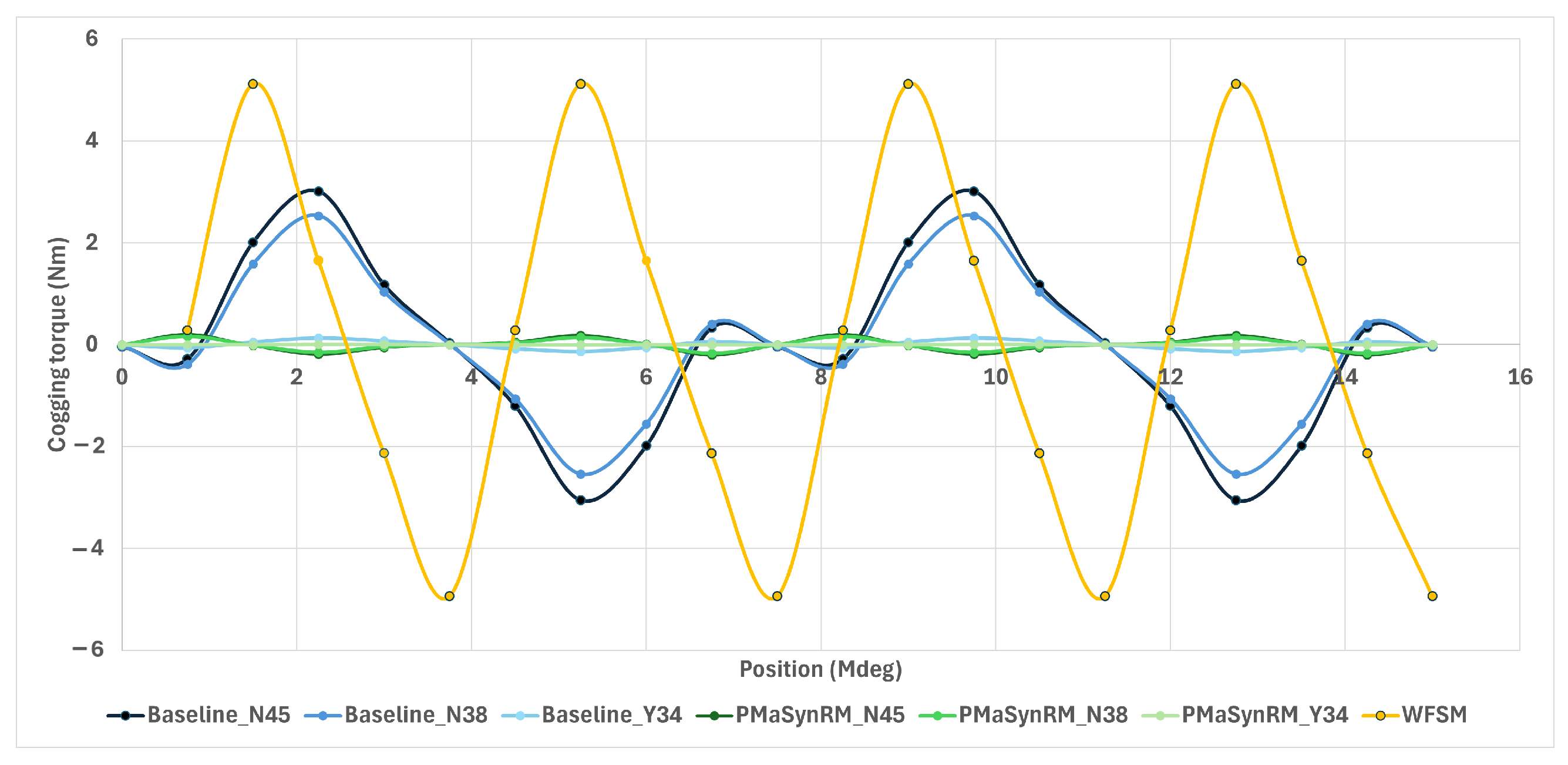
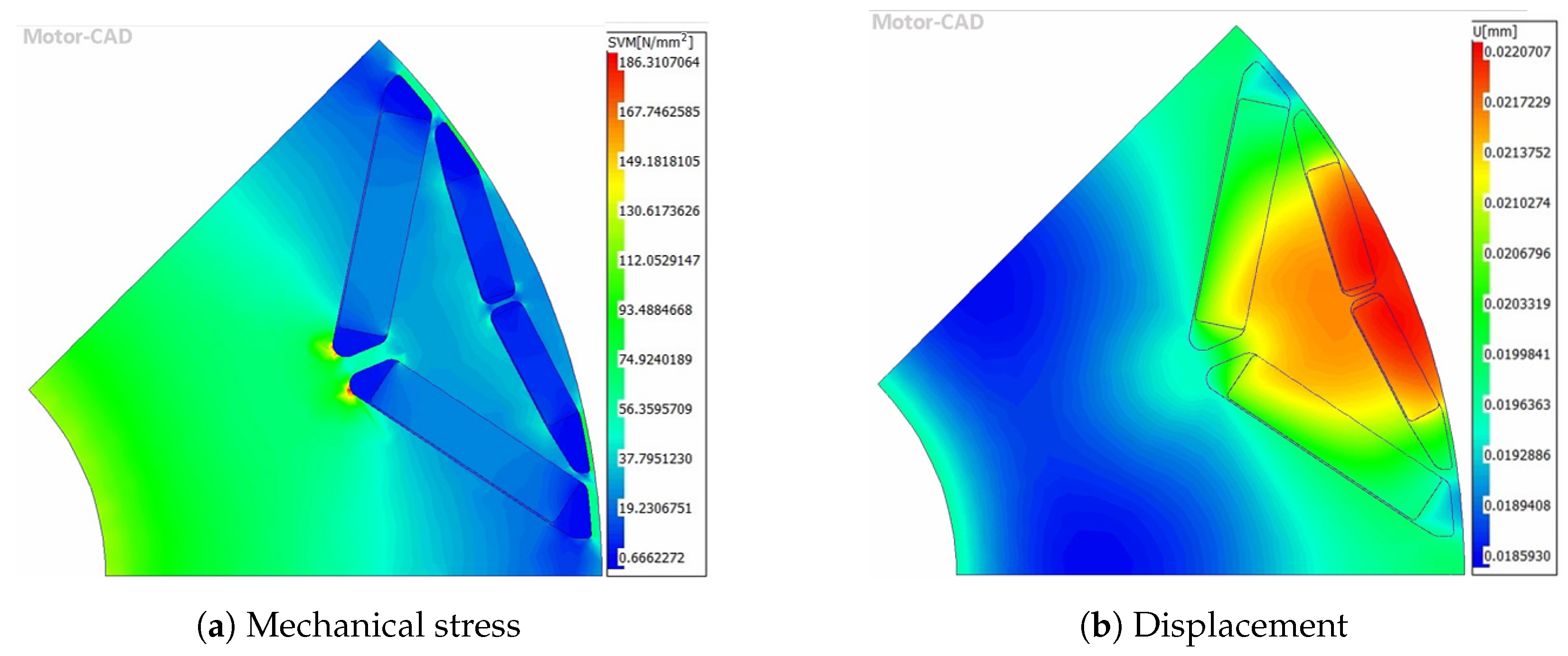
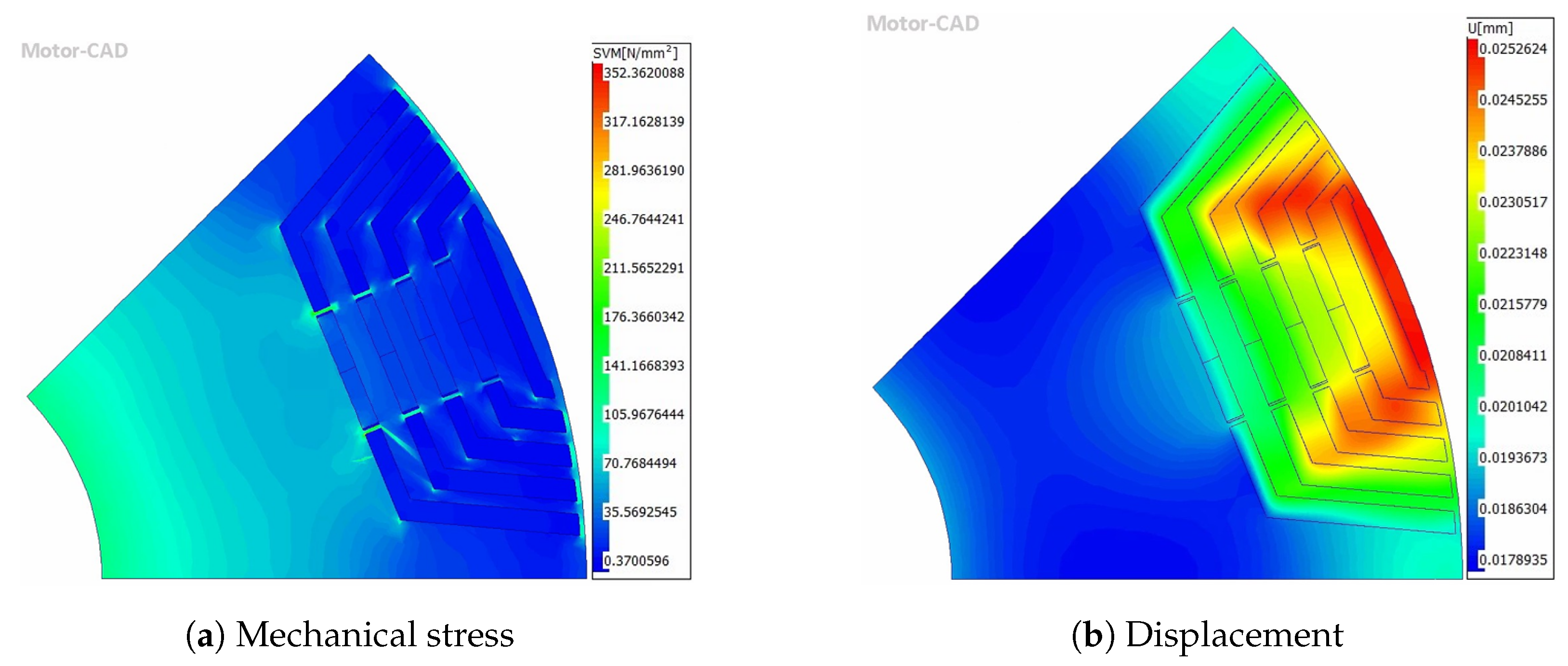
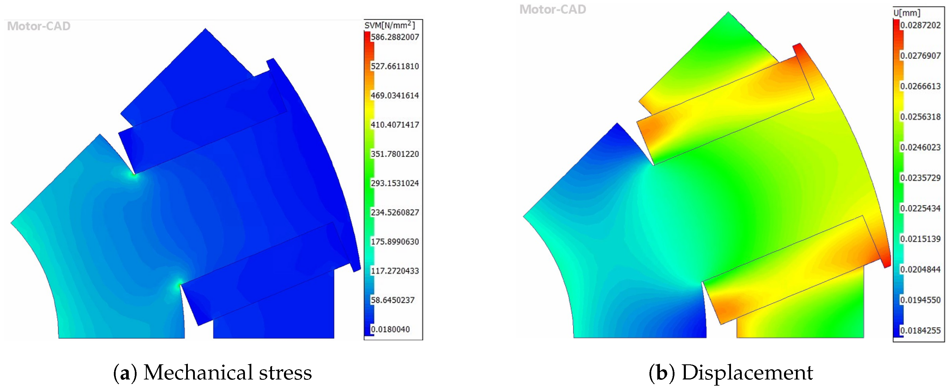
4.5. Mechanical and NVH Performance

Figure 18 elucidates the unwanted cogging torque contribution for each machine. Evidently, the WFSM produces the highest cogging torque, followed by the base machines with NdFeB magnets because of their higher magnetic alignment torque. The production of lower alignment torque from both the ferrite machines and the PMaSynRMs results in much lower cogging torque. Notably, due to their lower magnetic flux density, ferrites produce lower cogging torque in their respective topological groups.
The torque ripple for all machines was extracted from the output electromagnetic data at their respective torque peaks, occurring at slightly different values of phase advance due to the different contributions of reluctance torque. From Figure 19, it is clear that the PMaSynRMs with NdFeBs have lower torque ripple, followed by the WFSM at 5.4%. The machines using ferrites experience a notable increase in torque ripple when compared to the same topological group. As shown in Figure 18, this is clearly not sourced from cogging torque. Rather, the changes in axial length (and magnet density) could be generating harmonics in the back-EMF waveform [75].
Figure 20a,b show the mechanical stress and displacement that occurs at 14,400 rpm (20% overspeed) for the base machine with N45UH magnets and epoxy-filled rotor pockets. Stress concentrations are most pronounced at the inner rotor and extend toward the inner tip of the first rotor pocket, where the stress levels peak at 186 MPa. Lesser stress concentrations are observed at the bridges, as expected. Despite these variations, the PMSM operates with a factor of safety of 2.39 and an average stress of 43.9 MPa. The corresponding peak displacement of 0.02 mm is deemed acceptable and is concentrated in the gap between the layers and outer magnet layer bridge section, presenting no issues with rotor-stator clearance.
Figure 21a shows the stress experienced within a section of the PMaSynRM. The tangential ribs bear much of the force as well as the bridges. Noting that the yield stress of the electrical steel is 445 MPa, the stress model shows an acceptable level of stress with an average of 27.08 MPa. It is likely that the peak of 352 MPa is found in the corners, which could be rectified by employing larger magnet and lamination corner radii. The displacement of the flux barriers of the machine in Figure 21b is highest near the bridge of the outermost flux barrier and could be critical if the distance between the air gap was compromised. Fortunately, the displacement reaches no more than 0.025 mm, which is an acceptable level, encroaching no more than 2.5% of the air gap.
Despite an average mechanical stress of 68.6 MPa, the rotor experiences two maxima in the corners (570 MPa), which is beyond the yield stress in Figure 22a. However, this should not be a cause for concern for the topology with an adjustment of the corner radii. Displacement is highest in the pole-edge tips at 0.028 mm and the winding in Figure 22b. Study [70] identified stress concentrations in the same locations, all of which were significantly below their material’s yield stress because of smoother corner radii on either side of the rotor winding.
It is important to note that due to the slight decrease in density that the recycling process yields, a marginal decrease in stress is seen in these variations. The use of ferrites results in a more pronounced decrease in stress and displacement due to the ferrite density of 4800 kg/m3 versus 7600 kg/m3 for the N45UH magnets. These are shown in Table 5.

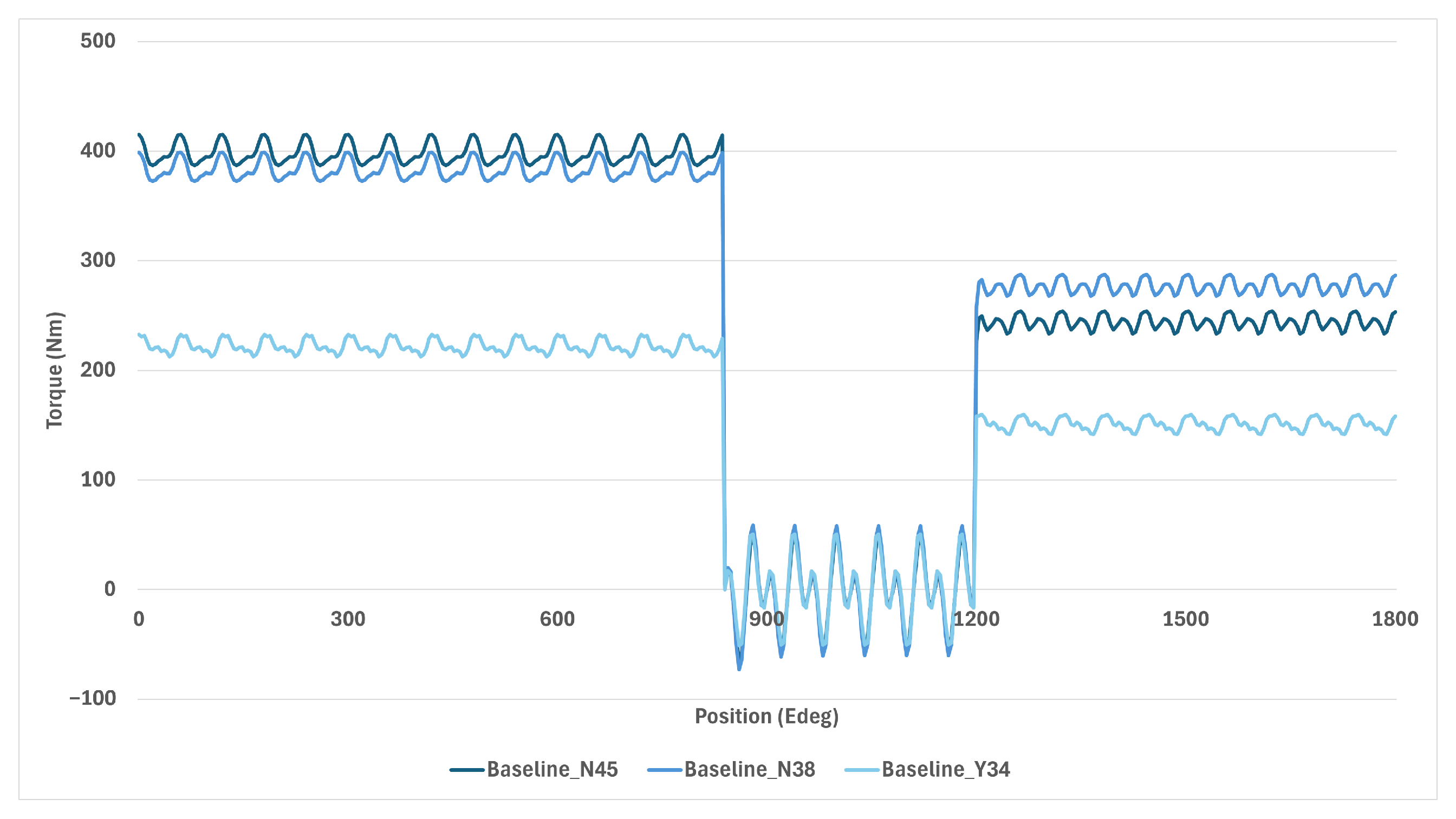
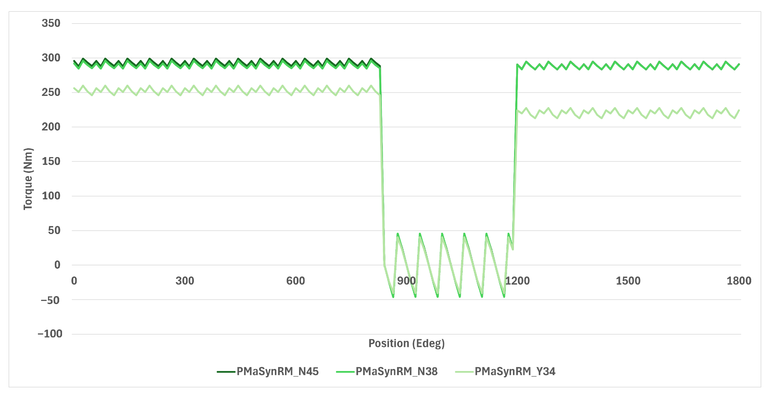
4.6. Demagnetisation Resilience

During the demagnetisation event, a short-circuit fault was assumed to occur whose peak current in the direct quadrature axis was input into the subsequent demagnetisation calculation. The magnet temperature was set to 160 °C and the winding at 180 °C. Due to this, the ferrite maximum torque production is inhibited before the event. Figure 23 shows the effect on torque production for the base machines before and after a short circuit demagnetisation event. Interestingly, despite starting from a similar torque, the recycled magnets were able to produce higher torque after the event, dropping by 27% versus 39% for the primary magnets. This is likely due to slightly higher intrinsic coercivity at 2025 KA/m, versus 1910 KA/m for the primary magnet. Only a 21% drop was experienced by the machine with ferrites, although this result may be skewed from its much lower starting point.
Figure 24 shows the demagnetisation event for all of the PMaSynRMs. Here, the difference between the primary and secondary magnets is indistinguishable after th event. The effect on all machines is very small due to much lesser reliance on the PM for magnetic alignment torque. The machine with primary magnets experiences only a 1.5% torque reduction, with secondary magnets it is only 0.4%, and with ferrite magnets, it is greater at 14.3%. The difference in the starting peak torque between the PMaSynRMs and the base machines is likely due to the different phase advances specified in the torque drive cycle file. The optimal/peak for the PMSM machines is 40/45°, but for the PMaSynRMs it is 50°. Table 6 summarises the findings from both topologies.

5. Discussion

This section discusses the previous results section in terms of cost, recommendations for practice, contributions to knowledge, limitations, and how to take the research further.

5.1. Cost Analysis

The estimated material costs for each active material constituent are shown in Table 7. Estimations for the machine materials are guided by a combination of [74], commodity price data, and respective cost fluctuations between the approximate publish date (taken as August 2020 for simplicity) and the writing of this research (10 August 2024). The study assumed 2 GBP/kg for steel laminations. Since then, the steel commodity price has decreased 19.6% [76]. Considering that the initial cost was for a thicker steel lamination (0.5 mm) compared to NO18-160 (0.18 mm), and acknowledging the higher cost of thinner grades, a price of 2.50 GBP/kg is reasonable [77]. The shaft was assumed to decrease in the same proportion due to the same raw steel material. The raw price of copper in this time period has increased 39.6%, increasing the assumed price to 12.30 GBP/kg [78].
Total machine costs are highly sensitive to magnet costs, making accurate magnet estimation essential. The study assumed a cost of 100 GBP/kg for N42SH, a magnet grade with a lower maximum energy product and Curie temperature compared to N45UH. However, considering both the grade differences and a recent 3.8% increase in the price of Nd-compound, the study adopted an adjusted value of 130 GBP/kg for N45UH magnets [6]. For recycled magnets, the raw cost of scrap material was estimated at 4 EUR/kg in Germany in 2017 [27]. However, the primary cost driver for obtaining recycled magnets is the recycling process, which remains relatively undeveloped and likely costly. To estimate the total cost of recycled magnets, one method is to apply the same manufacturing costs (55% of the total) of primary magnets, which would be 71.50 GBP/kg. Combining this value with the scrap material cost, the estimated total for recycling magnets is approximately 75 GBP/kg. For the ferrite magnets, studies have assumed values in the range of USD 7–18.50 [79,80,81]. Therefore, a value in this range of 8 GBP/kg was assumed after converting to GBP.
The baseline machine with N45UH magnets is the most expensive at GBP 447, followed by the PMaSynRM with the same magnets, as it requires more active material to meet peak torque. Increased use of electrical steel and multiple flux barriers adds to the cost through higher scrap mass. Machines using recycled magnets offer significant cost savings while maintaining similar performance to the baseline. Ferrite-based machines are slightly cheaper due to lower ferrite prices, but they require more active material to achieve equivalent torque. The WFSM, at GBP 220, is the least expensive due to its omission of PMs and moderate material use. However, machines with reduced or non-primary NdFeB magnets show only minor cost savings, raising concerns about their justification given potential performance trade-offs, particularly in peak power. Figure 25 shows the estimated material costs for each active material constituent in each machine.
Figure 26 shows the integral of peak and continuous performances per unit cost of the machines. This is also an indicator of whether the machine is thermally limited in the difference between the peak and continuous values. The best machine for peak performance per unit cost is the WFSM. However, this machine is thermally constrained by a substantial margin, with the area of the peak curve almost twice that of the continuous curve. Due to a greater length and mediocre performance, this resulted in a lower power per unit cost. Interestingly, the base machine with recycled magnets presents itself as the best option per unit cost for continuous performance due to a substantially better continuous performance than the other topologies, whilst at a moderate cost. The PMaSynRM with ferrite magnets is inferior in both peak and continuous performance relative to cost, due to its longer axial length.

5.2. Research Credibility

Similarities between the results in this research project and other works add to the credibility and validation of the research. The results agree with the conclusion in [82] that the torque density of PM machines is much higher than WFSM machines. Thermally, a higher rotor temperature in the WFSM and copper loss roughly double that of the PMSM is also agreed upon. Mechanically, the same stress concentration areas are found [70]. However, due to smoother radii, the stress reaches much lower peaks. Study [71] compared multiple topologies, including a PMSM and a WFSM (of the same template) with similar calculation settings. Whilst the peak performances do not match those of the study, continuous performance is very similar despite using water jacket cooling. Specifically, the PM machine generates substantially higher continuous torque but is overtaken at high rotational speed. In the continuous power curve, the PMSM drops steeply in power production at high speed. Adding to similarities, the shapes of each efficiency map are very similar, the WFSM is heavier, the PMSM achieves slightly higher efficiency, and the losses are higher for the WFSM. In the performance difference between the PMaSynRM and the PMSM, ref. [48] also finds a higher advance angle for the PMaSynRM due to higher reluctance torque. Additionally, magnet reduction between the two machines is similar at 63% in their study and 55% in this study.
When considering the performance impact of ferrites and NdFeBs in PMaSynRMs, the results are consistent with the findings in [51,83]. The use of NdFeB magnets in PMaSynRMs led to higher torque density, lower torque ripple, greater efficiency, and a shorter stack length compared to ferrites. Moreover, the ferrite-based machine could not achieve the same peak and continuous power as the machine using NdFeB magnets and would need to be larger and heavier to produce the same torque. Additionally, the investigation of the PMaSynRM with ferrites supports the conclusion that this machine, while much cheaper, exhibits poorer performance across the speed range compared to a PMSM.
When confirming the reliability of recycled magnets’ performance, several findings align with those reported in [12]. Although the study focused on a brushless DC motor, the effects are analogous, demonstrating that recycled magnets are a sustainable and cost-efficient alternative to primary NdFeB magnets with similar performance. This conclusion is further supported by [13], where recycled magnets were shown to outperform ferrites in terms of electromagnetic performance, highlighting their viability. Additionally, agreement is found in the high torque capability and increased efficiency of recycled magnets.
However, while most results align with [12], a few discrepancies are present. For instance, a greater torque production with recycled magnets was observed in their study due to a higher remanence value. This difference arises from the addition of an RE-rich compound during the recycling process (m2m®), which this study assumes does not occur. Differences in power and torque densities are found when comparing to [70]. These differences are due to the consideration of only active materials in the analysis, excluding factors such as housing and epoxy. Additionally, the findings in [71] indicate some variations in peak performance. Their WFSM produces better overall power, while this study yields significantly lower peak power. Moreover, the base speed of the WFSM is lower than that of the PMSM in this study. These differences are attributed to the scaling of their machine power, which was not endeavoured in this study.
An unexpected result in this study was the superior performance of the recycled magnets in the continuous performance envelope. Whilst there is no previous research to suggest that this is surprising, it is generally inferred from studies that compare weaker magnets (ferrites) and stronger magnets (NdFeB) that greater performance across the speed range can be expected [1,51,83]. The probable cause is the 6% difference in coercivity between the primary and secondary magnets. Whilst no specific confirmation example exists, ref. [84] suggests that a higher coercive force increases the torque and efficiency. Another possible reason is the difference in magnetic squareness between the magnets that arises from the change in microstructure incurred during the recycling process [85].
The PMaSynRMs have the lowest average stress in their rotors, which contradicts typical mechanical concerns with the topology [50]. However, this may be due to a much lesser magnet use which reduces centrifugal forces on the lamination as well as the addition of tangential ribs which reduce stress concentrations [33]. The final unexpected result was the higher torque ripple observed in PMSMs compared to PMaSynRMs [86]. Torque ripple in PMSMs is influenced by a wide range of factors and is part of a complex multiphysics interaction [87]. Consequently, it is concluded that the cause of this higher torque ripple is multifaceted and cannot be attributed to a single factor.

5.3. Recommendations for Practice

The performance impact of using secondary NdFeB magnets in conventional machines like PMSMs is understudied in the literature. Whilst RE recovery of NdFeB swarf from manufacturing is well-established, the same cannot be said for the EOL stage [2,88]. If high-volume magnet recycling can be invested in, the manufacturing of cheaper yet still very competent machines is possible, as shown by the similar performance in Section 4.1 and Section 4.4. The recommendation for practice is that economical mass-market recycling plants sourcing a variety of the densest NdFeB sources should be developed. The choice between different recycling methods such as HD, m2m®, and melt-spinning should be evaluated between cost and performance. This can promote a circular economy for NdFeB magnets, who have shown their propensity for multiple recycled lives [26]. For recycled magnets to be widely adopted, their cost must remain below that of primary N38UH magnets, as OEMs may resist using lower-grade options if performance is compromised.
The use of ferrites in EMs reduces costs but at the expense of performance. When normalised for cost-to-performance, the base machine with ferrites offers mid-tier performance, with the PMaSynRM exhibiting the lowest ratio. Thus, it is not recommended in practice to add ferrites into the PMaSynRM topology for automotive application.
The low base speed of PMaSynRMs, as indicated in Section 4.1, could pose a problem for traction applications. Therefore, a recommendation to practice would be to focus on optimising this machine with a 720 V+ drive to enhance both power and base speed.
In the simulations, the WFSM proved to be a strong magnet-free option, outperforming PMaSynRMs in torque density and base speed. However, the exciter mechanism is a significant drawback, especially since brushed systems, while common, require regular maintenance, which is a concern in the EV market. Although brushed WFSMs are viable for mass-market applications, the adoption of WPT solutions remains uncertain, with no industry examples available. Adding WPT devices would increase the cost, complexity, weight, and volume of the drive package [82]. While transformer-based designs offer a compact solution, they may impede the spray cooling of the machine. Ultimately, brushless exciters would be the most desirable option.
The weighted Pugh matrix in Figure 27 was created as a holistic evaluation tool, considering a mass-market outlook for an OEM based on the simulation results.
The asterisk by the ‘actualisation’ criteria indicates ratings based on literature review rather than empirical data, reflecting factors like feasibility and technology maturity. Machines using ferrites score positively due to stable material sourcing, while those with recycled magnets score negatively due to limited industry maturity. The matrix’s flexible weighting allows different machines to score better depending on OEM preferences.
Key attributes were weighted from 1 to 4, with 4 being the most important. The baseline machine with N45UH magnets served as the reference, scoring 0 on a scale from −3 (inferior) to +3 (superior). Machines were then evaluated based on the simulation results. The PMaSynRM with ferrites performed the worst overall due to poor tractive performance. The baseline ferrite machine, while better than the reference machine overall, still performed poorly in torque density and NVH, with only marginally inferior tractive performance relative to cost. The NdFeB PMaSynRM, despite its higher cost due to N45UH magnets, had notably worse tractive performance relative to cost. Secondary magnets improved cost and sustainability while maintaining performance. The top-performing machines are the baseline machine with secondary magnets and the WFSM, which slightly outperforms it. The asterisk for mechanical robustness indicates potential issues that could be resolved by adjusting corner radii, as demonstrated by similar designs in [70]. Whilst the WFSM cannot provide the same continuous performance as the reference machine, it is a much cheaper option that is highly sustainable, unaffected by demagnetisation, and its performance-to-cost ratio is much better.

5.4. Limitations to Research

Simulation results inherently have limitations without experimental validation. Computational methods may not fully capture certain phenomena, such as the effects of manufacturing on an EM [72]. While the PMSM and WFSM machines are based on established templates, the PMaSynRM was based on designs in the literature [48,89] due to the lack of exact geometrical data, resulting in a non-optimised machine. It is acknowledged that Motor-CAD has limited flexibility in machine topologies, meaning that novel/unconventional machines cannot be simulated, unlike in Ansys Maxwell [90].
The WFSM simulations assume a brushless exciter, which may not reflect real-world conditions as a WPT system would add energy losses and mass, potentially reducing base speed and limiting transferability to real life application. Collaborations between industry and academia could address these issues by supplying data on brush friction losses or inertia changes with a WPT device.
The assumption that led to the derivation of the recycled magnets is limited by the validity of study [91]. Assumptions are also based on the Δ % change of properties between the scrap magnet and the resultant magnet after the first recycling. It cannot be fully assumed that magnet recycling has the same effect on all grades, especially considering both temperature and strength grade variations. Additionally, the inability to alter the magnetic alignment of the recycled magnets in the software could result in different electromagnetic behaviour [92].
It is reported that ferrite grades up to Y40 are available [93]. These are among the strongest commercially, but Motor-CAD’s material library only includes up to Y34 ferrite, and full data for a Y40 magnet would require supplier liaison, which was beyond the scope of the study. Substituting Y34 (a slightly weaker magnet) for Y40 has a negligible impact, as inferred by this study’s findings. In both PMSM and PMaSynRM topologies, only a 2.9–3.5% volume increase was needed to match the original EM torque when using recycled instead of virgin magnets. The energy product difference between Y40 and Y34 is approximately 16%, slightly less than the 18% difference between N45UH and its recycled counterpart, suggesting the performance impact of using Y34 is similarly minimal or even less significant.
Importantly, the component costs were estimated due to a lack of available data, which could impact the performance-cost ratios reported. While this may slightly distort the net score, it is unlikely to change the final decision-matrix result as it mostly relies on performance data.

5.5. Suggestions for Future Research

In addressing a limitation of the study, future research could optimise the topologies to understand the performance difference under optimised designs, implemented using parametric optimisation algorithms to produce a Pareto front [94,95]. From this, the topology superior to the entire set of solutions could be chosen. For recycled magnets, further research is required in assessing the performance of recycled magnets in EMs to build on the foundations of [12,13]. The focus should be on evaluating large-scale recycling techniques on metrics such as magnetic property retention, cost, scrap magnet sourcing, energy use, and CO2 footprint. These metrics would be significant because they would supply the crucial information needed to adopt the technology.
Future research on rotor excitation in the WFSM should focus on a solution that is compact, light, cheap, mass-market manufacturable, and non-obstructing for cooling. In the same way, AFMs show much promise as well as HE topologies that use ferrites and RE materials as well as integrating WFSMs with RE/REF designs. These should be designed for traction-specific applications and validated by a prototype to indicate real-world feasibility. Additionally, novel SRM machines like double-stator switched reluctance machines (DSSRMs) and induction switched reluctance machines (ISRMs) like those in [39,40] should be explored for mass-market manufacturability.
More extensive academic and industry research is necessary to explore alternative RE-free magnets, especially focusing on the challenging synthesis of MnBi and FeN [17,19]. Achieving a viable product could potentially mirror the groundbreaking development of NdFeB magnets in the 1980s.

6. Conclusions

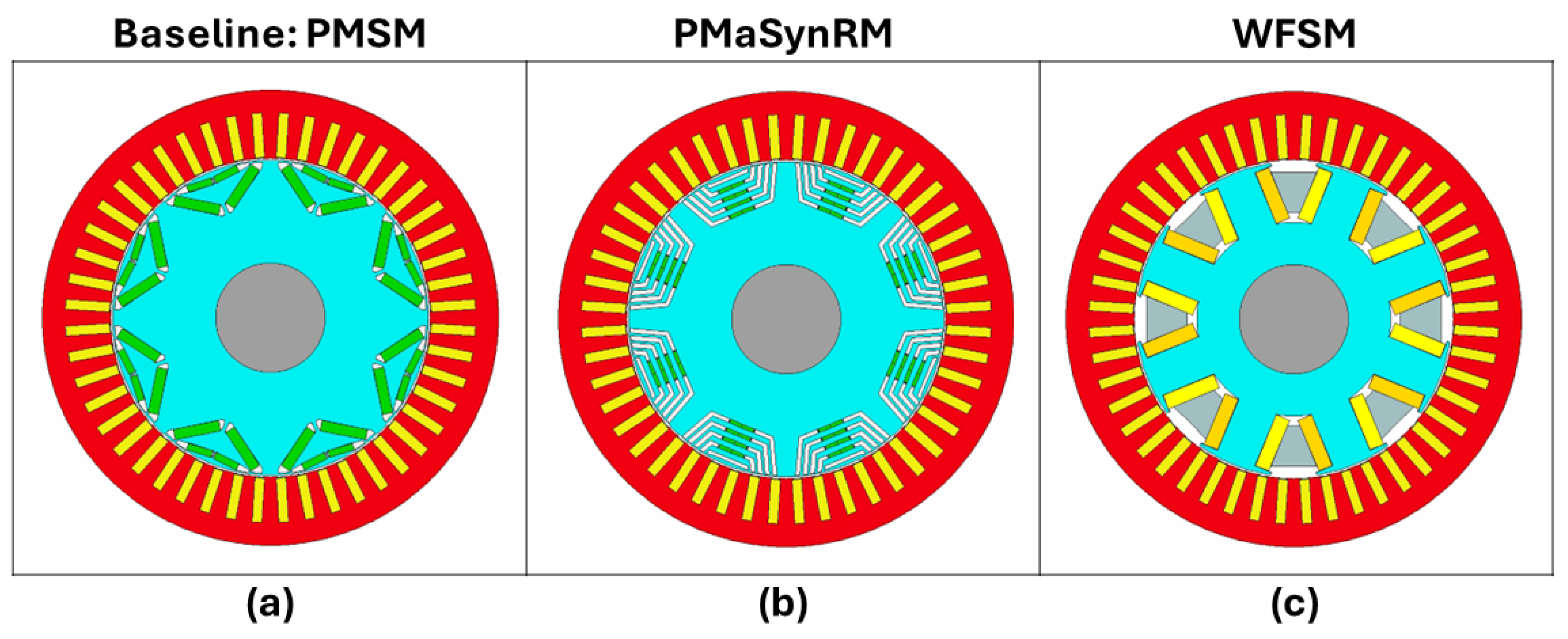
  • The simulation results revealed that recycled NdFeB magnets were a cost-effective and sustainable alternative, offering performance comparable to primary NdFeB magnets with minimal volume increases of 3.5% for the PMSM and 2.9% for the PMaSynRM to achieve equivalent peak torque. In contrast, ferrite magnets required substantial volume increases—82% for PMSM and 31% for PMaSynRM—leading to lower torque density and higher torque ripple.
  • The reference PMSM with virgin magnets achieved the highest gravimetric torque density at 11.5 Nm/kg, while the PMaSynRM with ferrites had the lowest at 6.5 Nm/kg.
  • The PMSM with recycled magnets demonstrated superior high-speed and high-temperature performance compared to primary magnets.
  • The use of ferrites exhibited increased torque ripple and reduced performance over the torque–speed curve. During demagnetisation, the recycled magnets showed a 27% torque decrease compared to 39% for primary NdFeB and 21% for ferrites, with PMaSynRM experiencing minimal demagnetisation impacts. The PMaSynRMs also had the lowest torque ripple.
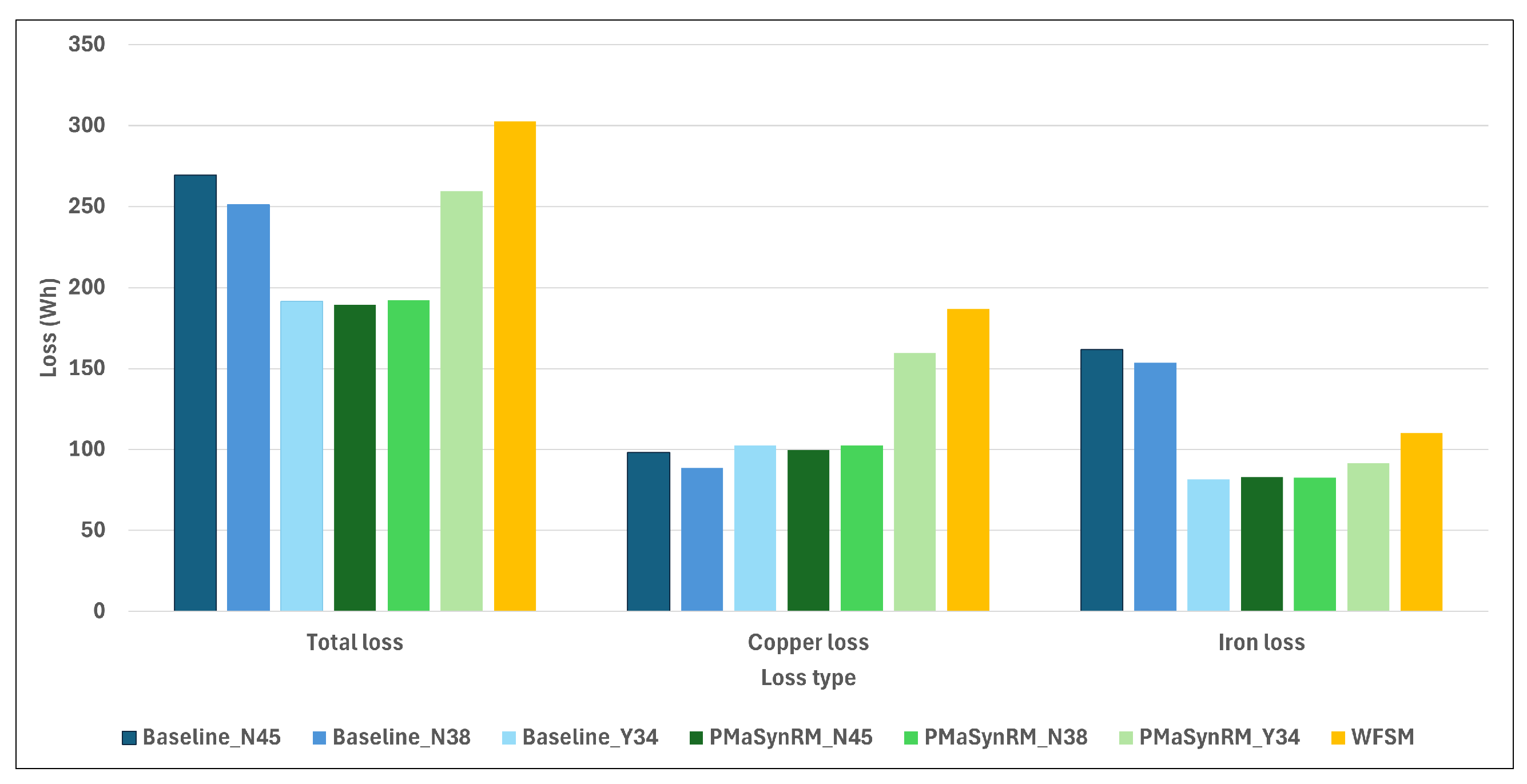
  • During the WLTP Class 3 drive cycle, the WFSM incurred the highest losses at 302 Wh, but over the drive cycle, the baseline machine with N45UH magnets was inferior. NdFeB-based PMSMs had the highest iron loss but the lowest copper loss. The PMaSynRM with N45UH magnets and the reference PMSM with ferrites achieved the highest energy efficiency at 96.3% and 96.2%, respectively, with overall drive cycle efficiencies of 94.3% and 93.9%.
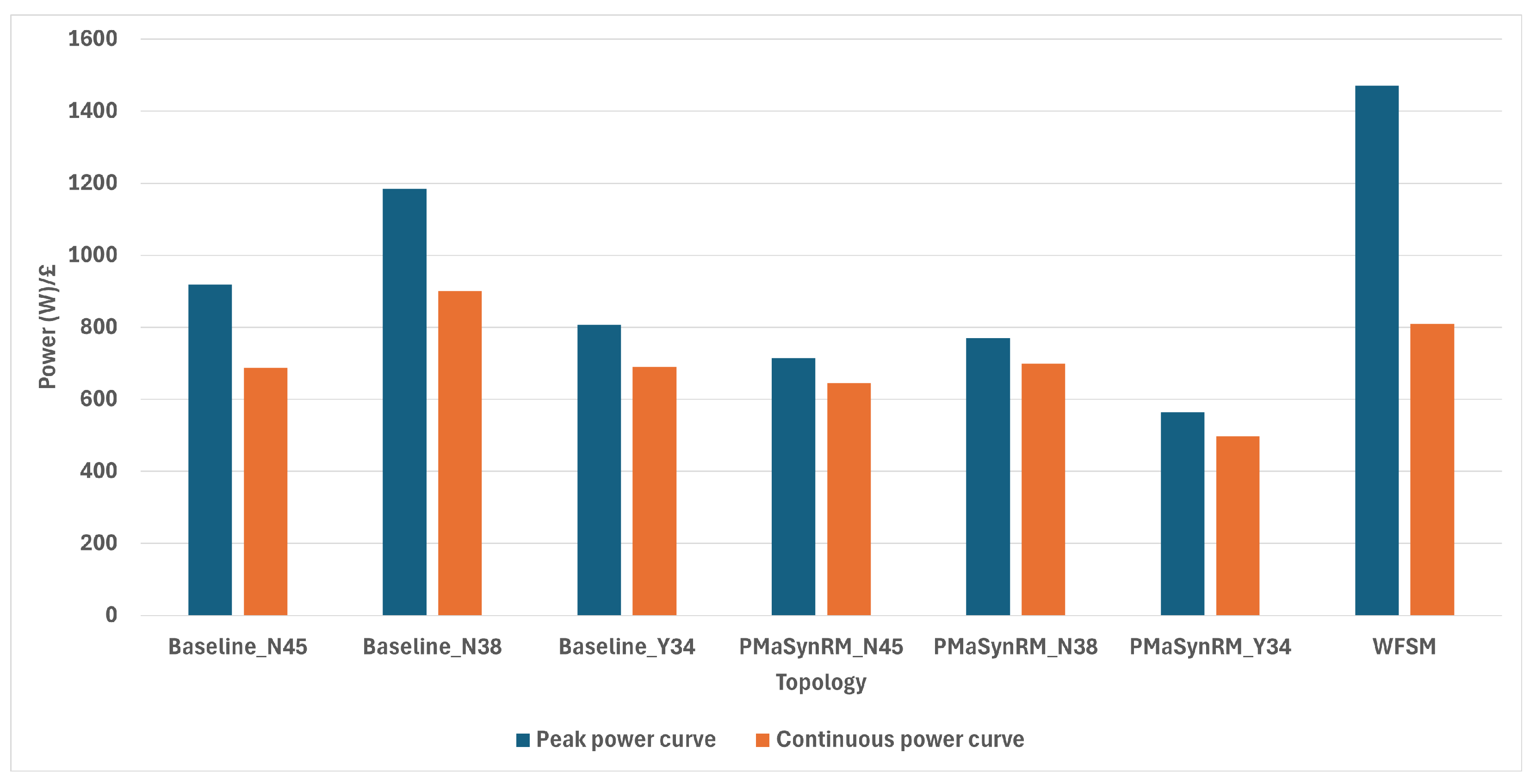
  • The cost analysis revealed that the PMSM with N45UH magnets was the most expensive at GBP 447, the PMaSynRM at GBP 368, and the WFSM at GBP 220. The WFSM also offered the best peak performance value-for-money at ∑ 1.47 MW/GBP, while the reference PMSM had the highest continuous performance efficiency at ∑ 0.90 MW/GBP, compared to the lowest values for the PMaSynRM at ∑ 0.56 MW/GBP and ∑ 0.50 MW/GBP.
  • The Pugh matrix analysis highlighted that, despite ongoing issues, the WFSM emerged as the most favourable overall solution for the machine variations simulated due to its cost-effectiveness and high-speed performance.
This study demonstrates that recycled NdFeB magnets can achieve comparable performance to virgin magnets. A key contribution is the apples-to-apples performance comparison of rare-earth magnet-reducing topologies, in which a PMSM was compared with a PMaSynRM and a WFSM with both virgin and recycled magnets. Future research direction would include holistic magnet recycling feasibility, novel machine topology manufacturing and feasibility, and practical WFSM excitement methods. Table 8 summarises all key data extracted from each machine.

Author Contributions

Conceptualization, O.M.L. and M.A.; methodology, O.M.L.; software, O.M.L.; validation, O.M.L. formal analysis, O.M.L.; investigation, O.M.L.; data curation, O.M.L.; writing—original draft preparation, O.M.L.; writing—review and editing, O.M.L. and M.A.; visualization, O.M.L.; supervision, M.A.; funding acquisition, M.A. All authors have read and agreed to the published version of the manuscript.

Funding

The APC was funded by University of Warwick.

Data Availability Statement

The data presented in this study are available on request from the corresponding author.

Conflicts of Interest

The authors declare no conflicts of interest.

Abbreviations

The following abbreviations are used in this manuscript:
PMSMPermanent magnet synchronous machine
WFSMWound-field synchronous machine
AFMAxial flux machine
SRMSwitched reluctance machines
RERare-earth
HEVHybrid electric vehicle
EMElectric machine
WPTWireless power transfer
GHGGreenhouse gas
EVElectric vehicle
ICEInternal combustion engine
CPMConsequent pole machine
CPSRConstant power speed range
PPower
τ Torque
MGOeMegagauss-Oersteds
NdFeBNeodymium-iron-boron
B r Magnetic remanence
MnBiManganese-bismuth
SmCoSamarium-cobalt
B H m a x Maximum energy product
SmFeNSamarium-iron-nitride
FeNIron-nitride
AlNiCoAluminum-Nickel-Cobalt
EOLEnd-of-life
HDHydrogen decrepitation
OEMOriginal equipment manufacturer
IPMInterior permanent magnet
B-N45Baseline machine with N45UH neodymium magnets
B-N38Baseline machine with recycled (N45UH) neodymium magnets
B-Y34Baseline machine with Y34 ferrite magnets
P-N45Permanent magnet-assisted synchronous reluctance machine with N45UH neodymium magnets
P-N38Permanent magnet-assisted synchronous reluctance machine with recycled (N45UH) neodymium magnets
P-Y34Permanent magnet-assisted synchronous reluctance machine with Y34 ferrite magnets
CPCCapacitive power coupler
ATFAutomatic transmission fluid
τ Torque
SPMSurface permanent magnet
PMaSynRMPermanent magnet-assisted synchronous reluctance machine
PMPermanent magnet

Appendix A. Simulation Settings

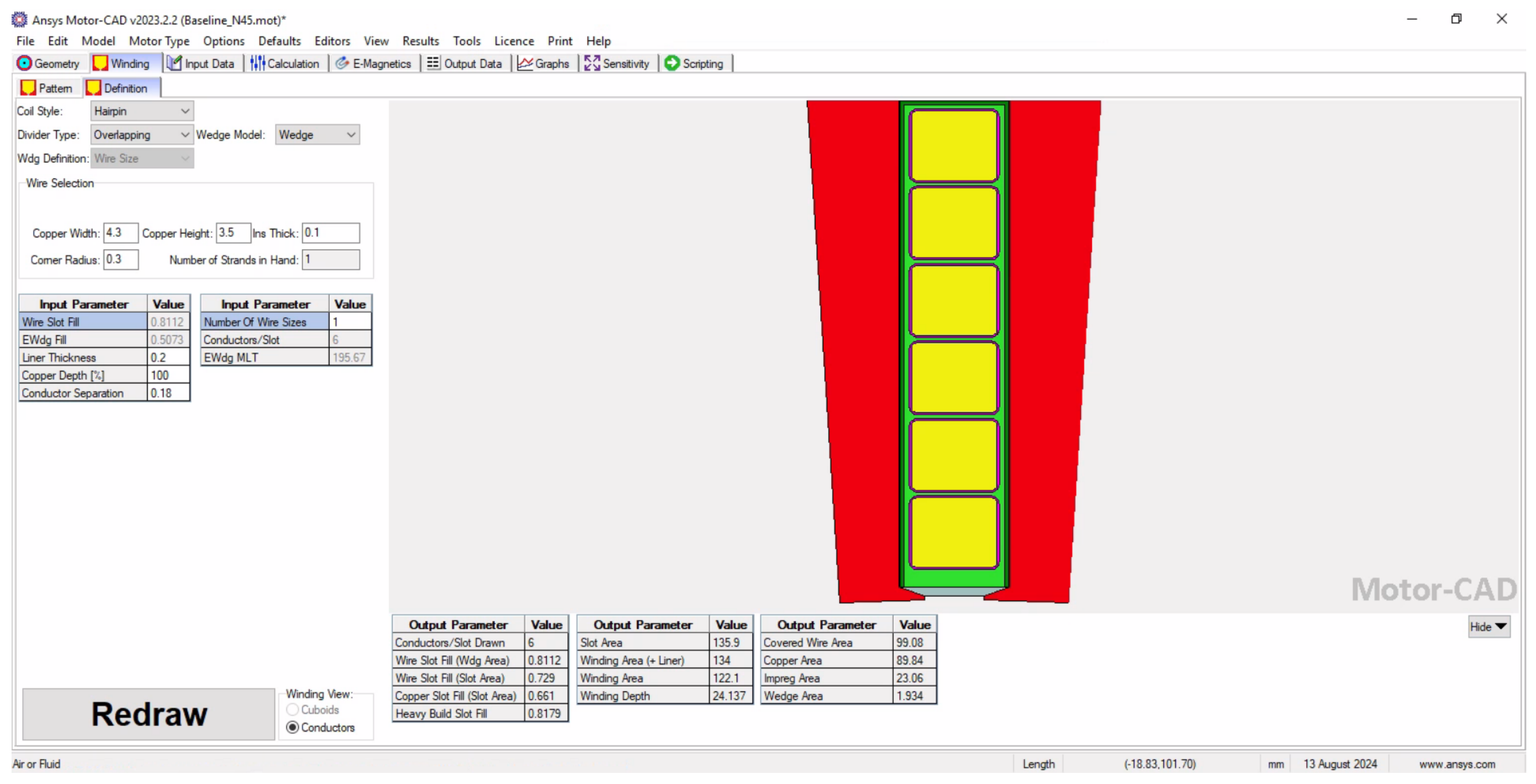
Appendix A.1. Hairpin Winding Setup

Figure A1. The winding pattern settings for all machines.
Energies 18 02274 g0a1
Figure A2. The winding dimensions of each layer.
Energies 18 02274 g0a2
Figure A3. The direction and relative magnitude of the ATF spray cooling used for all machines as indicated by arrows.
Energies 18 02274 g0a3

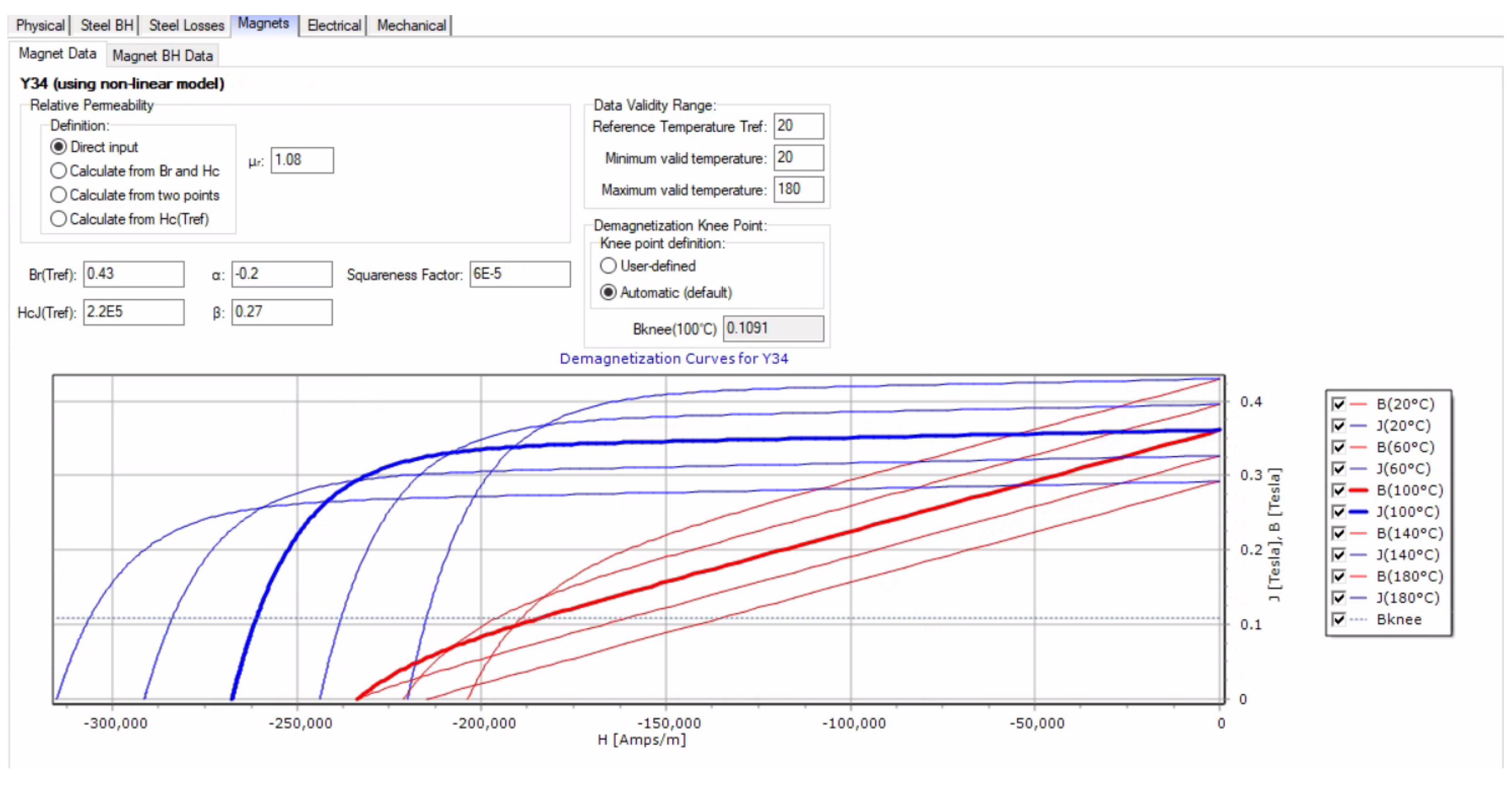
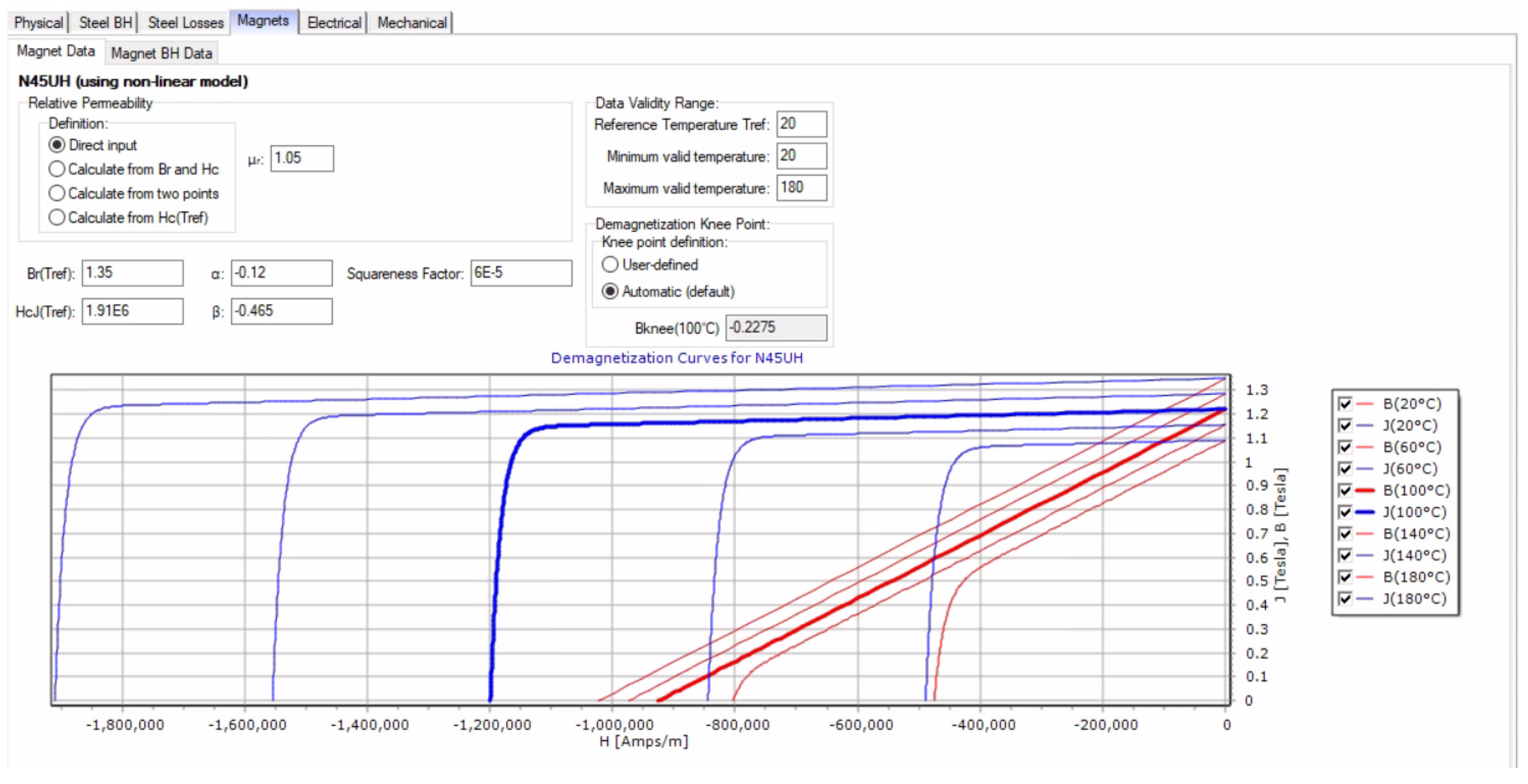
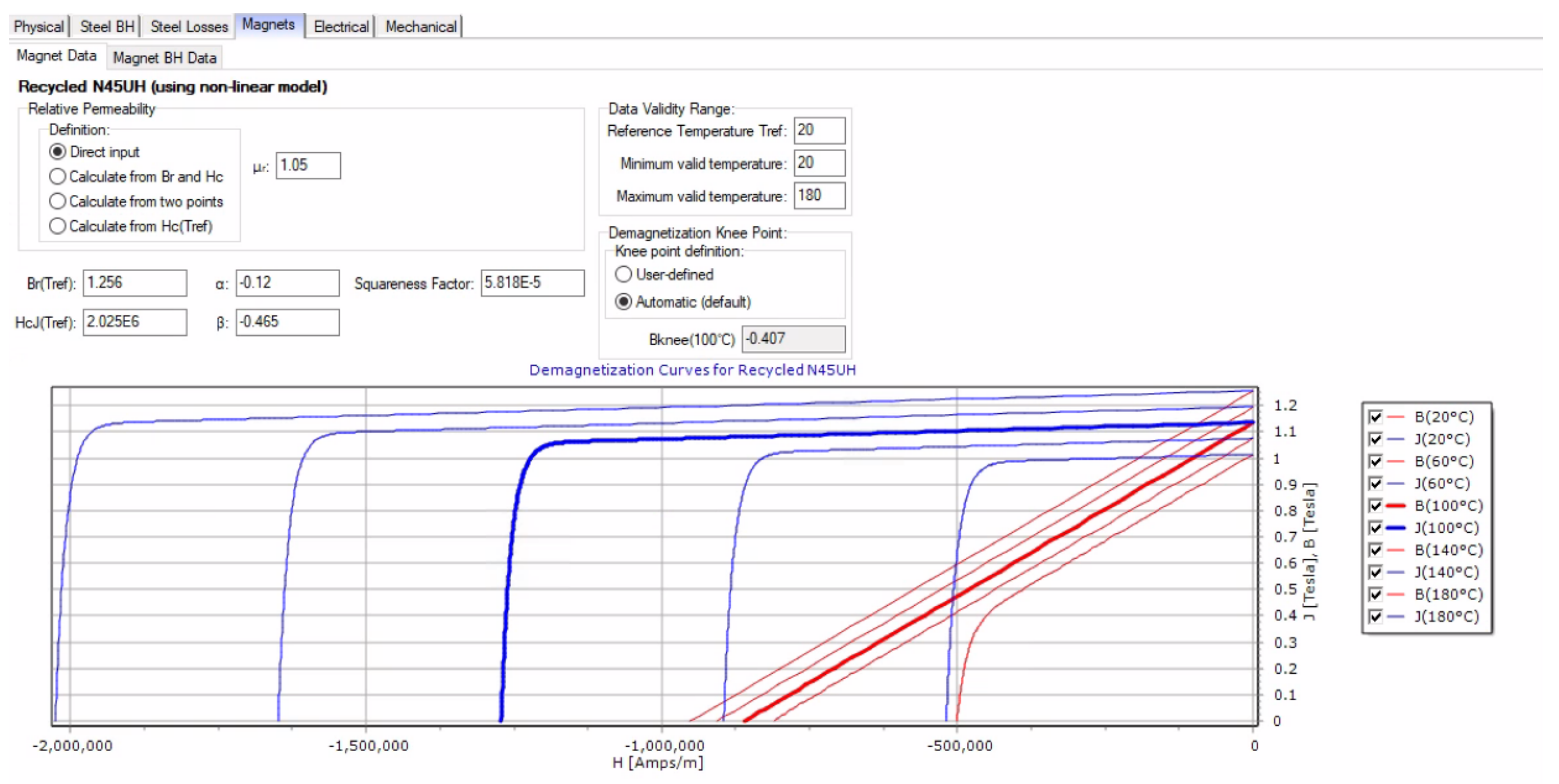
Appendix A.2. Magnet Data

Figure A4. Ferrite (Y34) magnet data used for the simulations.
Energies 18 02274 g0a4
Figure A5. N45UH magnet data used for the simulations.
Energies 18 02274 g0a5
Figure A6. Recycled magnet data used for the simulations.
Energies 18 02274 g0a6

References

  1. Poudel, B.; Amiri, E.; Rastgoufard, P.; Mirafzal, B. Toward Less Rare-Earth Permanent Magnet in Electric Machines: A Review. IEEE Trans. Magn. 2021, 57, 900119. [Google Scholar] [CrossRef]
  2. Yang, Y.; Walton, A.; Sheridan, R.; Güth, K.; Gauß, R.; Gutfleisch, O.; Buchert, M.; Steenari, B.M.; Van Gerven, T.; Jones, P.T.; et al. REE recovery from end-of-life NdFeB permanent magnet scrap: A critical review. J. Sustain. Metall. 2017, 3, 122–149. [Google Scholar] [CrossRef]
  3. Statista. Distribution of Carbon Dioxide Emissions Worldwide in 2023, by Sector. Available online: https://www.statista.com/statistics/1129656/global-share-of-co2-emissions-from-fossil-fuel-and-cement/ (accessed on 1 July 2024).
  4. European Commision. Air. Available online: https://environment.ec.europa.eu/topics/air_en (accessed on 9 July 2024).
  5. Statista. Change in Average Temperature by Decade Worldwide from 1910 to 2019, by Region (in Degrees Celsius)*. Available online: https://www.statista.com/statistics/1062474/difference-temperature-decade-worldwide/ (accessed on 1 July 2024).
  6. SDM Magnets. PrNd Price Trend. Available online: https://www.magnet-sdm.com/prnd-price-trend/ (accessed on 4 July 2024).
  7. Statista. Breakdown of New Car Sales in the European Union in 2023, by Segment (in Million Vehicles). Available online: https://www.statista.com/statistics/1413689/european-union-car-sales-distribution-by-segment/ (accessed on 2 July 2024).
  8. Hioki, K. Development of High-Performance Hot-Deformed Neodymium–Iron–Boron Magnets without Heavy Rare-Earth Elements. Materials 2023, 16, 6581. [Google Scholar] [CrossRef] [PubMed]
  9. IDTechEx. Electric Motors for Electric Vehicles 2024–2034. Available online: https://www.idtechex.com/en/research-report/electric-motors-for-electric-vehicles-2024-2034/941 (accessed on 4 July 2024).
  10. Bailey, G.; Mancheri, N.; Van Acker, K. Sustainability of permanent rare earth magnet motors in (H) EV industry. J. Sustain. Metall. 2017, 3, 611–626. [Google Scholar] [CrossRef]
  11. Advanced Propulsion Centre UK. Electric Machines. Available online: https://www.apcuk.co.uk/knowledge-base/resource/electric-machines-roadmap/ (accessed on 3 July 2024).
  12. Prosperi, D.; Bevan, A.; Ugalde, G.; Tudor, C.; Furlan, G.; Dove, S.; Lucia, P.; Zakotnik, M. Performance comparison of motors fitted with magnet-to-magnet recycled or conventionally manufactured sintered NdFeB. J. Magn. Magn. Mater. 2018, 460, 448–453. [Google Scholar] [CrossRef]
  13. Kimiabeigi, M.; Sheridan, R.S.; Widmer, J.D.; Walton, A.; Farr, M.; Scholes, B.; Harris, I.R. Production and Application of HPMS Recycled Bonded Permanent Magnets for a Traction Motor Application. IEEE Trans. Ind. Electron. 2018, 65, 3795–3804. [Google Scholar] [CrossRef]
  14. Petrelli, G.; Nuzzo, S.; Zou, T.; Barater, D.; Franceschini, G.; Gerada, C. Review and future developments of wound field synchronous motors in automotive. In Proceedings of the 2023 IEEE International Conference on Electrical Systems for Aircraft, Railway, Ship Propulsion and Road Vehicles & International Transportation Electrification Conference (ESARS-ITEC), Venice, Italy, 29–31 March 2023; IEEE: Piscataway, NJ, USA, 2023; pp. 1–6. [Google Scholar]
  15. Chai, W.; Kwon, J.W.; Kwon, B.I. Analytical Design of a Hybrid-Excited Wound Field Synchronous Machine for the Improvement of Torque Characteristics. IEEE Access 2020, 8, 87414–87421. [Google Scholar] [CrossRef]
  16. Ghosh, M.K.; Grainger, B.; McElhinny, S.; Brody, R.; Cui, J.; Sherman, A.; Ohodnicki, P. Multiphysics Design and Optimization of a Rare-Earth Free, Manganese Bismuth Based, Surface Mounted Permanent Magnet Machine. In Proceedings of the 2023 IEEE Transportation Electrification Conference & Expo (ITEC), Detroit, MI, USA, 21–23 June 2023; pp. 1–7. [Google Scholar] [CrossRef]
  17. Rom, C.L.; Smaha, R.W.; O’Donnell, S.; Dugu, S.; Bauers, S.R. Emerging magnetic materials for electric vehicle drive motors. MRS Bull. 2024, 49, 738–750. [Google Scholar] [CrossRef]
  18. Al-Qarni, A.; El-Refaie, A. Optimum Rotor Design for Rare-Earth Free High Performance Traction Applications Interior Permanent Magnet Motors Enabled by Iron Nitride Permanent Magnet. In Proceedings of the 2023 IEEE International Electric Machines & Drives Conference (IEMDC), San Francisco, CA, USA, 15–18 May 2023; pp. 1–7. [Google Scholar] [CrossRef]
  19. Saito, T.; Yamamoto, H.; Nishio-Hamane, D. Production of Rare-Earth-Free Iron Nitride Magnets (a-Fe16N2). Metals 2024, 14, 734. [Google Scholar] [CrossRef]
  20. Keszler, M.; Grosswendt, F.; Assmann, A.C.; Krengel, M.; Maccari, F.; Gutfleisch, O.; Sebold, D.; Guillon, O.; Weber, S.; Bram, M. Direct Recycling of Hot-Deformed Nd–Fe–B Magnet Scrap by Field-Assisted Sintering Technology. Adv. Energy Sustain. Res. 2024, 5, 2300184. [Google Scholar] [CrossRef]
  21. Coey, J. Perspective and Prospects for Rare Earth Permanent Magnets. Engineering 2020, 6, 119–131. [Google Scholar] [CrossRef]
  22. Shakelly, N.; Pérez-Cardona, J.R.; Pan, C.; Cui, J.; Sutherland, J.W. Techno-Economic Assessment of a Novel Continuous Hot-Roll Process for Manufacturing Nanograin NdFeB Magnets. Procedia CIRP 2024, 122, 133–138. [Google Scholar] [CrossRef]
  23. Magnet Motion. HOT FORMED NdFeB MAGNETS (MQ3). Available online: https://magnetemotion.com/technology-mq3-ndfeb-extrusion.html (accessed on 5 July 2024).
  24. Sprecher, B.; Kleijn, R.; Kramer, G.J. Recycling potential of neodymium: The case of computer hard disk drives. Environ. Sci. Technol. 2014, 48, 9506–9513. [Google Scholar] [CrossRef] [PubMed]
  25. Zakotnik, M.; Harris, I.; Williams, A. Multiple recycling of NdFeB-type sintered magnets. J. Alloys Compd. 2009, 469, 314–321. [Google Scholar] [CrossRef]
  26. Schönfeldt, M.; Rohrmann, U.; Schreyer, P.; Hasan, M.; Opelt, K.; Gassmann, J.; Weidenkaff, A.; Gutfleisch, O. Magnetic and structural properties of multiple recycled and sustainable sintered Nd-Fe-B magnets. J. Alloys Compd. 2023, 939, 168709. [Google Scholar] [CrossRef]
  27. Diehl, O.; Schönfeldt, M.; Brouwer, E.; Dirks, A.; Rachut, K.; Gassmann, J.; Güth, K.; Buckow, A.; Gauß, R.; Stauber, R.; et al. Towards an alloy recycling of Nd–Fe–B permanent magnets in a circular economy. J. Sustain. Metall. 2018, 4, 163–175. [Google Scholar] [CrossRef]
  28. Hughes, A.; Drury, B. Electric Motors and Drives: Fundamentals, Types and Applications; Newnes: Oxford, UK, 2019. [Google Scholar]
  29. Cao, Z.; Mahmoudi, A.; Kahourzade, S.; Soong, W.L. An Overview of Electric Motors for Electric Vehicles. In Proceedings of the 2021 31st Australasian Universities Power Engineering Conference (AUPEC), Perth, Australia, 26–30 September 2021; pp. 1–6. [Google Scholar] [CrossRef]
  30. Agamloh, E.; von Jouanne, A.; Yokochi, A. An Overview of Electric Machine Trends in Modern Electric Vehicles. Machines 2020, 8, 20. [Google Scholar] [CrossRef]
  31. Krings, A.; Monissen, C. Review and Trends in Electric Traction Motors for Battery Electric and Hybrid Vehicles. In Proceedings of the 2020 International Conference on Electrical Machines (ICEM), Gothenburg, Sweden, 23–26 August 2020; Volume 1, pp. 1807–1813. [Google Scholar] [CrossRef]
  32. Thomas, R.; Husson, H.; Garbuio, L.; Gerbaud, L. Comparative study of the Tesla Model S and Audi e-Tron Induction Motors. In Proceedings of the 2021 17th Conference on Electrical Machines, Drives and Power Systems (ELMA), Sofia, Bulgaria, 1–4 July 2021; pp. 1–6. [Google Scholar] [CrossRef]
  33. Credo, A.; Fabri, G.; Villani, M.; Popescu, M. Adopting the Topology Optimization in the Design of High-Speed Synchronous Reluctance Motors for Electric Vehicles. IEEE Trans. Ind. Appl. 2020, 56, 5429–5438. [Google Scholar] [CrossRef]
  34. Lan, Y.; Benomar, Y.; Deepak, K.; Aksoz, A.; Baghdadi, M.E.; Bostanci, E.; Hegazy, O. Switched Reluctance Motors and Drive Systems for Electric Vehicle Powertrains: State of the Art Analysis and Future Trends. Energies 2021, 14, 2079. [Google Scholar] [CrossRef]
  35. Chiba, A.; Kiyota, K.; Hoshi, N.; Takemoto, M.; Ogasawara, S. Development of a Rare-Earth-Free SR Motor with High Torque Density for Hybrid Vehicles. IEEE Trans. Energy Convers. 2015, 30, 175–182. [Google Scholar] [CrossRef]
  36. Bogusz, P.; Korkosz, M.; Prokop, J.; Daraż, M. Analysis Performance of SRM Based on the Novel Dependent Torque Control Method. Energies 2021, 14, 8203. [Google Scholar] [CrossRef]
  37. Lan, Y.; Frikha, M.A.; Croonen, J.; Benômar, Y.; El Baghdadi, M.; Hegazy, O. Design Optimization of a Switched Reluctance Machine with an Improved Segmental Rotor for Electric Vehicle Applications. Energies 2022, 15, 5772. [Google Scholar] [CrossRef]
  38. Xu, Z.; Li, T.; Zhang, F.; Zhang, Y.; Lee, D.H.; Ahn, J.W. A Review on Segmented Switched Reluctance Motors. Energies 2022, 15, 9212. [Google Scholar] [CrossRef]
  39. Abbasian, M.; Moallem, M.; Fahimi, B. Double-stator switched reluctance machines (DSSRM): Fundamentals and magnetic force analysis. IEEE Trans. Energy Convers. 2010, 25, 589–597. [Google Scholar] [CrossRef]
  40. Jazi, M.A.; Abbasian, M.; Gerling, D. Preliminary Evaluation of Induction Switched Reluctance Machine (ISRM) for Electric Vehicle Application. IEEE Access 2022, 10, 26693–26701. [Google Scholar] [CrossRef]
  41. Li, Y.; Wang, Y.; Zhang, Z.; Li, J. Investigation and Development of the Brushless and Magnetless Wound Field Synchronous Motor Drive System for Electric Vehicle Application. World Electr. Veh. J. 2023, 14, 81. [Google Scholar] [CrossRef]
  42. Chen, H.; Tang, J.; Liu, Y.; Jiang, B.; Boscaglia, L. Electromagnetic Performance Investigation of A Brushless Electrically-Excited Synchronous Machine for Long-Distance Heavy-Duty Electric Vehicles. IEEE Trans. Transp. Electrif. 2024, 11, 225–235. [Google Scholar] [CrossRef]
  43. Stancu, C.; Ward, T.; Rahman, K.M.; Dawsey, R.; Savagian, P. Separately Excited Synchronous Motor With Rotary Transformer for Hybrid Vehicle Application. IEEE Trans. Ind. Appl. 2018, 54, 223–232. [Google Scholar] [CrossRef]
  44. Ludois, D.C.; Reed, J.K.; Hanson, K. Capacitive Power Transfer for Rotor Field Current in Synchronous Machines. IEEE Trans. Power Electron. 2012, 27, 4638–4645. [Google Scholar] [CrossRef]
  45. Raminosoa, T.; Wiles, R. Contactless Rotor Excitation for Traction Motors. In Proceedings of the 2018 IEEE Energy Conversion Congress and Exposition (ECCE), Portland, OR, USA, 23–27 September 2018; pp. 6448–6453. [Google Scholar] [CrossRef]
  46. Fallows, D.; Nuzzo, S.; Galea, M. Exciterless Wound-Field Medium-Power Synchronous Machines: Their History and Future. IEEE Ind. Electron. Mag. 2022, 16, 44–51. [Google Scholar] [CrossRef]
  47. Pellegrino, G.; Vagati, A.; Boazzo, B.; Guglielmi, P. Comparison of Induction and PM Synchronous Motor Drives for EV Application Including Design Examples. IEEE Trans. Ind. Appl. 2012, 48, 2322–2332. [Google Scholar] [CrossRef]
  48. Huynh, T.A.; Hsieh, M.F. Comparative Study of PM-Assisted SynRM and IPMSM on Constant Power Speed Range for EV Applications. IEEE Trans. Magn. 2017, 53, 8211006. [Google Scholar] [CrossRef]
  49. Artetxe, G.; Caballero, D.; Prieto, B.; Martinez-Iturralde, M.; Elosegui, I. Eliminating rare earth permanent magnets on low-speed high-torque machines: A performance and cost comparison of synchronous reluctance machines, ferrite permanent magnet-synchronous reluctance machines and permanent magnet synchronous machines for a direct-drive elevator system. IET Electr. Power Appl. 2021, 15, 370–378. [Google Scholar]
  50. Zheng, S.; Zhu, X.; Xiang, Z.; Xu, L.; Zhang, L.; Lee, C.H. Technology trends, challenges, and opportunities of reduced-rare-earth PM motor for modern electric vehicles. Green Energy Intell. Transp. 2022, 1, 100012. [Google Scholar] [CrossRef]
  51. Rajini, V.; Nagarajan, V.; Bharath Kumar, S.; Barathkumar, M.; Balaji, R.; Manojshyaam, C. Comparative analysis of Synchronous Reluctance Motor with different Permanent Magnet materials. Mater. Today Proc. 2022, 62, 738–745. [Google Scholar] [CrossRef]
  52. Zhang, L.; Liu, X.; Ouyang, X.; Chen, W. Characteristic analysis of conventional pole and consequent pole IPMSM for electric vehicle application. Energy Rep. 2022, 8, 259–269. [Google Scholar] [CrossRef]
  53. Qi, J.; Zhu, Z.Q.; Yan, L.; Jewell, G.W.; Gan, C.; Ren, Y.; Brockway, S.; Hilton, C. Effect of Pole Shaping on Torque Characteristics of Consequent Pole PM Machines. IEEE Trans. Ind. Appl. 2022, 58, 3511–3521. [Google Scholar] [CrossRef]
  54. Huang, R.; Song, Z.; Zhao, H.; Liu, C. Overview of Axial-Flux Machines and Modeling Methods. IEEE Trans. Transp. Electrif. 2022, 8, 2118–2132. [Google Scholar] [CrossRef]
  55. Patterson, D.J.; Colton, J.L.; Mularcik, B.; Kennedy, B.J.; Camilleri, S.; Rohoza, R. A comparison of radial and axial flux structures in electrical machines. In Proceedings of the 2009 IEEE International Electric Machines and Drives Conference, Miami, FL, USA, 3–6 May 2009; pp. 1029–1035. [Google Scholar] [CrossRef]
  56. Sun, W.; Li, Q.; Sun, L.; Li, L. Development and Investigation of Novel Axial-Field Dual-Rotor Segmented Switched Reluctance Machine. IEEE Trans. Transp. Electrif. 2021, 7, 754–765. [Google Scholar] [CrossRef]
  57. Chen, Y.; Cai, T.; Zhu, X.; Fan, D.; Wang, Q. Analysis and Design of a New Type of Less-Rare-Earth Hybrid-Magnet Motor with Different Rotor Topologies. IEEE Trans. Appl. Supercond. 2020, 30, 5200406. [Google Scholar] [CrossRef]
  58. Meyer, A.; von Lindenfels, J.; Mayr, A.; Franke, J. Manufacturing Imperfections in Electric Motor Production with Focus on Halbach Array Permanent Magnet Rotor Assembly. In Proceedings of the 2018 8th International Electric Drives Production Conference (EDPC), Schweinfurt, Germany, 4–5 December 2018; pp. 1–7. [Google Scholar] [CrossRef]
  59. Graffeo, F.; Stiscia, O.; Vaschetto, S.; Cavagnino, A.; Tenconi, A. Doubly Excitated Synchronous Machines for Traction Applications. In Proceedings of the 2021 IEEE 30th International Symposium on Industrial Electronics (ISIE), Kyoto, Japan, 20–23 June 2021; pp. 1–8. [Google Scholar] [CrossRef]
  60. Faiz, J.; Maktobian, M. Performance Enhancement of Flux Switching Motor for Electric Vehicle Applications: An Overview. IET Electr. Syst. Transp. 2024, 2024, 9071667. [Google Scholar] [CrossRef]
  61. Coteț, F.A.; Văscan, I.; Szabó, L. On the usefulness of employing ANSYS Motor-CAD software in designing permanent magnet synchronous machines. Designs 2023, 7, 7. [Google Scholar] [CrossRef]
  62. Ansys Motor-CAD. Integrated Multiphysics Analysis Software for Electric Motor Design. Available online: https://www.ansys.com/content/dam/product/electronics/motor-cad/ansys-motor-cad-brochure.pdf (accessed on 1 August 2024).
  63. Park, H.J.; Lim, M.S. Design of High Power Density and High Efficiency Wound-Field Synchronous Motor for Electric Vehicle Traction. IEEE Access 2019, 7, 46677–46685. [Google Scholar] [CrossRef]
  64. Kimiabeigi, M.; Widmer, J.D.; Long, R.; Gao, Y.; Goss, J.; Martin, R.; Lisle, T.; Soler Vizan, J.M.; Michaelides, A.; Mecrow, B. High-Performance Low-Cost Electric Motor for Electric Vehicles Using Ferrite Magnets. IEEE Trans. Ind. Electron. 2016, 63, 113–122. [Google Scholar] [CrossRef]
  65. Arnold Magnet Technologies. N45UH. Sintered Neodymium-Iron-Boron Magnets. Available online: https://www.arnoldmagnetics.com/wp-content/uploads/2017/11/N45UH-151021.pdf (accessed on 19 July 2024).
  66. Arnold Magnet Technologies. N38UH. Sintered Neodymium-Iron-Boron Magnets. Available online: https://www.arnoldmagnetics.com/wp-content/uploads/2017/11/N38UH-151021.pdf (accessed on 19 July 2024).
  67. Zhang, Y.; Cao, W.; McLoone, S.; Morrow, J. Design and Flux-Weakening Control of an Interior Permanent Magnet Synchronous Motor for Electric Vehicles. IEEE Trans. Appl. Supercond. 2016, 26, 1–6. [Google Scholar] [CrossRef]
  68. Wang, A.; Jia, Y.; Soong, W.L. Comparison of Five Topologies for an Interior Permanent-Magnet Machine for a Hybrid Electric Vehicle. IEEE Trans. Magn. 2011, 47, 3606–3609. [Google Scholar] [CrossRef]
  69. Niu, L.; Zhang, M. The Loss and Efficiency Analysis and Research of Interior Permanent Magnet Synchronous Motors for Traction Applications. IEEE Access 2023, 11, 5538–5557. [Google Scholar] [CrossRef]
  70. Di Gioia, A.; Brown, I.P.; Nie, Y.; Knippel, R.; Ludois, D.C.; Dai, J.; Hagen, S.; Alteheld, C. Design and Demonstration of a Wound Field Synchronous Machine for Electric Vehicle Traction With Brushless Capacitive Field Excitation. IEEE Trans. Ind. Appl. 2018, 54, 1390–1403. [Google Scholar] [CrossRef]
  71. Goss, J. Performance Analysis of Electric Motor Technologies for an Electric Vehicle Powertrain; White Paper; Motor Design Ltd.: Wrexham, UK, 2019. [Google Scholar]
  72. Wu, F.; Zhou, L.; Soulard, J.; Silvester, B.; Davis, C. Quantitative characterisation and modelling of the effect of cut edge damage on the magnetic properties in NGO electrical steel. J. Magn. Magn. Mater. 2022, 551, 169185. [Google Scholar] [CrossRef]
  73. Park, M.R.; Kim, D.M.; Jung, Y.H.; Lim, M.S. High energy efficiency oriented-control and design of WFSM based on driving condition of electric vehicle. Mechatronics 2022, 81, 102696. [Google Scholar] [CrossRef]
  74. Ma, X.Y.; Wang, X.Y.; Soulard, J. Design procedure of 48v in-wheel outer rotor spms for fully electric vehicles. In Proceedings of the 10th International Conference on Power Electronics, Machines and Drives (PEMD 2020), Online Conference, 5–17 December 2020; IET: London, UK, 2020; Volume 2020, pp. 128–133. [Google Scholar]
  75. Sumega, M.; Zoššák, S.; Varecha, P.; Rafajdus, P. Sources of torque ripple and their influence in BLDC motor drives. Transp. Res. Procedia 2019, 40, 519–526, TRANSCOM 2019 13th International Scientific Conference on Sustainable, Modern and Safe Transport. [Google Scholar] [CrossRef]
  76. Trading Economics. Steel. Available online: https://tradingeconomics.com/commodity/steel (accessed on 10 August 2024).
  77. Ma, X.Y.; Soulard, J.; Slater, C.; Davis, C. Influence of Electrical Steel Grade on Different Types of Traction Motors. In Proceedings of the 2022 International Conference on Electrical Machines (ICEM), Valencia, Spain, 5–8 September 2022; pp. 544–550. [Google Scholar] [CrossRef]
  78. Trading Economics. Copper. Available online: https://tradingeconomics.com/commodity/copper (accessed on 10 August 2024).
  79. Ma, Q.; El-Refaie, A.; Lequesne, B. Low-Cost Interior Permanent Magnet Machine with Multiple Magnet Types. IEEE Trans. Ind. Appl. 2020, 56, 1452–1463. [Google Scholar] [CrossRef]
  80. Prakht, V.; Dmitrievskii, V.; Kazakbaev, V.; Ibrahim, M.N. Comparison between rare-earth and ferrite permanent magnet flux-switching generators for gearless wind turbines. Energy Rep. 2020, 6, 1365–1369. [Google Scholar] [CrossRef]
  81. Özdemir, M.S.; Ocak, C.; Dalcalı, A. Permanent Magnet Wind Generators: Neodymium vs. Ferrite Magnets. In Proceedings of the 2021 3rd International Congress on Human-Computer Interaction, Optimization and Robotic Applications (HORA), Ankara, Turkey, 11–13 June 2021; pp. 1–6. [Google Scholar] [CrossRef]
  82. Chu, W.Q.; Zhu, Z.Q.; Chen, J.T. Simplified Analytical Optimization and Comparison of Torque Densities Between Electrically Excited and Permanent-Magnet Machines. IEEE Trans. Ind. Electron. 2014, 61, 5000–5011. [Google Scholar] [CrossRef]
  83. Al-ani, M.; Walker, A.; Vakil, G.; Gerada, D.; Gerada, C.; Paciura, K. Modifications to PM-Assisted Synchronous Reluctance Machine to Achieve Rare-Earth Free Heavy-Duty Traction. IEEE J. Emerg. Sel. Top. Power Electron. 2023, 11, 2029–2038. [Google Scholar] [CrossRef]
  84. Sakai, K.; Yuzawa, N. Effect of coercive force and characteristics of a pole changing permanent magnet motor for variable-speed drive. In Proceedings of the 2014 16th European Conference on Power Electronics and Applications, Lappeenranta, Finland, 26–28 August 2014; pp. 1–10. [Google Scholar] [CrossRef]
  85. Perigo, E.A.; Takiishi, H.; Motta, C.C.; Faria, R.N. On the Squareness Factor Behavior of RE-FeB (RE = Nd or Pr) Magnets Above Room Temperature. IEEE Trans. Magn. 2009, 45, 4431–4434. [Google Scholar] [CrossRef]
  86. Du, G.; Zhang, G.; Li, H.; Hu, C. Comprehensive Comparative Study on Permanent-Magnet-Assisted Synchronous Reluctance Motors and Other Types of Motor. Appl. Sci. 2023, 13, 8557. [Google Scholar] [CrossRef]
  87. Rafaq, M.S.; Midgley, W.; Steffen, T. A Review of the State of the Art of Torque Ripple Minimization Techniques for Permanent Magnet Synchronous Motors. IEEE Trans. Ind. Inform. 2024, 20, 1019–1031. [Google Scholar] [CrossRef]
  88. Schönfeldt, M.; Opelt, K.; Hasan, M.; Gröninger, M.; Jahnke, D.; Gassmann, J.; Gutfleisch, O. Functional Recycling and Reuse of Nd–Fe–B Permanent Magnets from Various Waste Streams for a more Sustainable and Resilient Electromobility. Adv. Eng. Mater. 2025, 27, 2402815. [Google Scholar] [CrossRef]
  89. Huynh, T.A.; Hsieh, M.F.; Shih, K.J.; Kuo, H.F. An Investigation Into the Effect of PM Arrangements on PMa-SynRM Performance. IEEE Trans. Ind. Appl. 2018, 54, 5856–5868. [Google Scholar] [CrossRef]
  90. Tikhonova, O.; Malygin, I.; Plastun, A. Electromagnetic calculation for induction motors of various designs by ANSYS maxwell. In Proceedings of the 2017 International Conference on Industrial Engineering, Applications and Manufacturing (ICIEAM), St. Petersburg, Russia, 16–19 May 2017; IEEE: Piscataway, NJ, USA, 2017; pp. 1–5. [Google Scholar]
  91. München, D.D.; Veit, H.M. Neodymium as the main feature of permanent magnets from hard disk drives (HDDs). Waste Manag. 2017, 61, 372–376. [Google Scholar] [CrossRef] [PubMed]
  92. Huang, C.C.; Chien, C.L.; Chen, M.C.; Liu, C.S.; Lee, C.P. Effect of Magnetic Alignment and Magnetic Field Molding on Magnetic Properties of C-Shape Anisotropic Sr-Hexaferrites Permanent Magnets. IEEE Trans. Magn. 2024, 60, 2100108. [Google Scholar] [CrossRef]
  93. Eriksson, S.; Silva, M.D. Comparison of Simulation Methods for Angular Dependency When Modeling Demagnetization. In Proceedings of the 2023 IEEE International Magnetic Conference (INTERMAG), Sendai, Japan, 15–19 May 2023; pp. 1–5. [Google Scholar] [CrossRef]
  94. Shao, L.; Tavernini, D.; Hartavi Karci, A.E.; Sorniotti, A. Design and optimisation of energy-efficient PM-assisted synchronous reluctance machines for electric vehicles. IET Electr. Power Appl. 2023, 17, 788–801. [Google Scholar] [CrossRef]
  95. Song, T.; Liu, H.; Zhang, Q.; Zhang, Z. Multi-physics and multi-objective optimisation design of interior permanent magnet synchronous motor for electric vehicles. IET Electr. Power Appl. 2020, 14, 2243–2254. [Google Scholar] [CrossRef]
Figure 2. A map of explored solutions and topologies in the literature review.
Energies 18 02274 g002
Figure 3. Machine topologies used in the simulations. (a) Baseline: PMSM; (b) PMaSynRM; (c) WFSM.
Energies 18 02274 g003
Figure 4. Peak torque performance for all topologies and magnet combinations.
Energies 18 02274 g004
Figure 5. Peak power performance for all topologies and magnet combinations.
Energies 18 02274 g005
Figure 6. Comparison of major losses for each machine variation.
Energies 18 02274 g006
Figure 7. Efficiency based on energy use and in the WLTP class 3 drive cycle for all machine variations.
Energies 18 02274 g007
Figure 8. Baseline PMSM with N45UH magnets efficiency map.
Energies 18 02274 g008
Figure 9. Baseline machine with magnet substitutions.
Energies 18 02274 g009
Figure 10. PMaSynRM with N45UH magnets efficiency map.
Energies 18 02274 g010
Figure 11. PMaSynRM with magnet substitutions.
Energies 18 02274 g011
Figure 12. WFSM efficiency map.
Energies 18 02274 g012
Figure 13. Continuous torque performance curve for all topologies and magnet combinations.
Energies 18 02274 g013
Figure 14. Continuous power performance curve for all topologies and magnet combinations.
Energies 18 02274 g014
Figure 15. Comparison of steady-state machine temperatures at 6000 rpm. (ac) Baseline machines; (df) PMaSynRMs; (g) WFSM.
Energies 18 02274 g015
Figure 16. Baseline machine with N45UH magnets: transient calculation over one WLTP drive cycle.
Energies 18 02274 g016
Figure 17. Baseline machine with recycled magnets: transient calculation over one WLTP drive cycle.
Energies 18 02274 g017
Figure 18. Cogging torque versus mechanical degrees of all machine variations.
Energies 18 02274 g018
Figure 19. Torque ripple at peak torque for each machine variation.
Energies 18 02274 g019
Figure 20. (a) Mechanical stress. (b) Displacement on a section of the baseline machine at 14,400 rpm.
Energies 18 02274 g020
Figure 21. (a) Mechanical stress. (b) Displacement on a section of the PMaSynRM at 14,400 rpm.
Energies 18 02274 g021
Figure 22. (a) Mechanical stress. (b) Displacement on a section of the WFSM machine at 14,400 rpm.
Energies 18 02274 g022
Figure 23. The effects of a short-circuit demagnetisation event in the baseline machines.
Energies 18 02274 g023
Figure 24. The effects of a short-circuit demagnetisation event in the PMaSynRMs.
Energies 18 02274 g024
Figure 25. Cost comparison estimation of main machine components.
Energies 18 02274 g025
Figure 26. The total peak and continuous power performance/per unit cost (GBP).
Energies 18 02274 g026
Figure 27. Weighted Pugh matrix with reference to the baseline machine. * indicates ratings based on literature review rather than empirical data.
Energies 18 02274 g027
Table 1. Qualitative summary comparison of material properties and practical considerations for alternative magnet materials to sintered NdFeB where ‘+’ represents an advantage and ‘−’ a disadvantage.
Magnet MaterialMaterial PropertiesPractical Considerations
Recycled NdFeB+ Higher Coercivity+ Propensity to be cheaper
− Small reduction in B H m a x , B r , and squareness factor− High-volume recycling methods unproven
Polymer-bonded NdFeB+ Less brittle and isotropic+ Complex net-shapes possible
− Sizeable drop in B H m a x , B r and lowered coercivity− Less mainstream option means costlier
Hot-formed NdFeB+ Less Brittle, better corrosion resistance and similar B r + No heavy-RE additions
− Small drop in energy product− Less mainstream option means costlier
Iron nitride (FeN)+ Much higher theoretical B H m a x and B r + Abundant non-RE materials
− Lower coercivity and phase instability− Synthesis challenges = lower (actual) energy product
Manganese Bismuth (MnBi)+ Coercivity increases with temperature+ RE-free
− Low B H m a x and moderate B r − Poor oxidative stability and still experimental
Samarium Iron Nitride (SmFeN)+ Better demagnetisation resilience at (very) high temperatures, better corrosion resistance+ Abundant and lower demand
− Moderate B H m a x − Thermal instability during manufacture and contains Samarium (RE)
Table 2. Summary comparison of the investigated electric machine topologies compared to the permanent-magnet synchronous motor where ‘+’ represents an advantage and ‘−’ a disadvantage.
Machine TopologyMachine PerformancePractical Considerations
PMaSynRM+ Less susceptible to demagnetisation+ Less RE-magnet usage and cost
− Lower power/torque density,− Heavier and weaker mechanical robustness
IM+ Self-starting and reliable+ Low maintenance, cost-effective and no PMs
− Lower efficiency and torque/power density− Complex control methods
WFSM+ Wide CPSR, fault tolerance, good power/torque density+ No PMs and cost-effective
− Poor efficiency at low-medium speeds− Exciter complexity and maintenance
SynRM+ High reluctance torque, low torque ripple+ Low cost
− Poor power/torque density and narrow CPSR− Weak mechanical robustness
Novel SRMs 1+ High efficiency and torque density+ Prototypes demonstrate feasibility
− Torque ripple at low torque demands (ISRM)− Complex manufacturing and scalability unclear
Hybrid Excitation 2+ High torque density and potential for wide CPSR+ Reduced PM usage
− Moderate efficiency− Complex magnetic circuit and manufacturing
FSMs+ High efficiency, torque density and wide CPSR+ Simple rotor design
− Lower power factor− High stator complexity and limited research status
CPMs+ Nearly equivalent torque production to PMSm+ Lowered PM usage
− Weak induced poles− Limited research status
AFMs+ Very high torque/power density and high efficiency+ Flat, compact structure
− High cogging torque− Propensity for PM reduction unclear and complex manufacturing
1,2 Applies to most types of that machine topology but variation exists.
Table 3. Effect of recycling on N45UH magnets compared to N38UH magnets [26,65,66].
PropertyN45UHEffect
(Applied Δ %)
Recycled N45UHN38UH
Energy product (MGOe)45−14.938.338.0
Density (kg/m3)7600−2.973807600
Magnetic remanence (T)1.35−6.51.261.26
Intrinsic coercivity (kA/m)1910+6.220281990
Squareness factor 6.0 × 10 5 −3.0 5.8 × 10 5 6.0 × 10 5
Table 4. Gravimetric and volumetric torque densities of all machine variations based on active components.
AttributeB-N45B-N38B-Y34P-N45P-N38P-Y34WFSM
Mass (kg)34.836.157.449.350.562.141.8
Volume (m3) 4.23 × 10 3 4.38 × 10 3 7.69 × 10 3 6.73 × 10 3 6.93 × 10 3 8.80 × 10 3 5.69 × 10 3
Grav. τ density
(Nm/kg)
11.511.17.08.17.96.49.6
Vol. τ density
(Nm/L)
94.591.452.059.457.845.570.3
Table 5. Mechanical results for all machine variations.
AttributeB-N45B-N38B-Y34P-N45P-N38P-Y34WFSM
Peak stress (MPa)186185173352351329570
Average stress (MPa)43.943.539.527.127.026.368.6
Peak displacement (mm)0.0220.0220.0200.0250.0250.0240.029
Average displacement (mm)0.0200.0200.0190.0220.0220.0220.022
Safety factor2.392.402.571.261.271.350.76
Table 6. Demagnetisation effects on torque production for all topologies and magnet combinations.
AttributeB-N45B-N38B-Y34P-N45P-N38P-Y34WFSM
Pre-torque (Nm)399383222293289253-
Post-Torque (Nm)244277151288288217-
Change (%)−39−28−32−1.7−0.3−14.20
Table 7. Material cost estimations.
Machine ComponentMaterialCost (GBP/kg)Reference(s)
RotorN018-11602.50[74,76]
StatorN018-11602.50[74,76]
Electrical steel scrapN018-11600.25[74]
WindingCopper (Pure)12.30[74,78]
ShaftStahl 371.21[74,76]
MagnetsN45UH, recycled N45UH, ferrites130, 75, 8[6,27,74,79,80,81]
Table 8. Summary of the key results for each machine.
ParameterB-N45B-N38B-Y34P-N45P-N38P-Y34WFSM
Stack Length (mm)86.289.2156.7137.1141.1179.2115.9
Base speed (rpm)5200520030003200300024003800
Grav. τ density (Nm/kg)11.511.17.08.17.96.49.6
Vol. τ density (Nm/L)94.591.452.059.457.845.570.3
Torque ripple (%)7.77.49.44.64.87.75.5
Peak power (kW)236228126135131102162
∑ peak τ curve (MW)410403248263254183323
∑ cont. τ curve (MW)307306212238230162178
Reluctance torque (Nm)1801872503073133480
Efficiency (% use)91.7395.0896.2496.2796.2194.8093.36
Efficiency (% drive)91.2691.6094.3393.9493.9393.2191.54
Peak τ advance angle45°45°40°50°50°45°
Peak stress (MPa)186185173352351329570
Peak displacement (mm)0.0220.0220.0200.0250.0250.0240.029
Demagnetisation Δ τ (%)−39−28−32−1.7−0.3−14.20
Disclaimer/Publisher’s Note: The statements, opinions and data contained in all publications are solely those of the individual author(s) and contributor(s) and not of MDPI and/or the editor(s). MDPI and/or the editor(s) disclaim responsibility for any injury to people or property resulting from any ideas, methods, instructions or products referred to in the content.

