Article

A Comprehensive Analysis of Thermal Heat Dissipation for Lithium-Ion Battery Packs

1
Department of Mechanical and Industrial Engineering, Northeastern University, Boston, MA 02115, USA
2
NASA Glenn Research Center, Cleveland, OH 44135, USA
3
Ohio Aerospace Institute, Cleveland, OH 44142, USA
4
Department of Chemical Engineering, Northeastern University, Boston, MA 02115, USA
*
Author to whom correspondence should be addressed.
Energies 2025, 18(9), 2234; https://doi.org/10.3390/en18092234
Submission received: 24 March 2025 / Revised: 21 April 2025 / Accepted: 25 April 2025 / Published: 28 April 2025

Abstract

:
Effective thermal management is essential for the safe and efficient operation of lithium-ion battery packs, particularly in compact, airflow-sensitive applications such as drones. This study presents a comprehensive thermal analysis of a 16-cell lithium-ion battery pack by exploring seven geometric configurations under airflow speeds ranging from 0 to 15 m/s and integrating nano-carbon-based phase change materials (PCMs) to enhance heat dissipation. A Computational Fluid Dynamics (CFD) approach was employed using Ansys Discovery and Workbench 2024 R1 to simulate airflow and heat transfer processes with high spatial resolution. Using high-fidelity 3D simulations, we found that the trapezoidal wide-base configuration, combined with a 5-inlet and 1-outlet airflow design, achieved the most balanced cooling performance across all speed regimes. This configuration maintained battery temperatures within the optimal operating range (∼45 °C) in both low- and high-speed airflow conditions, with a maximum temperature reduction of up to 8.3 °C compared to the standard square configuration. Additionally, PCM integration extended the thermal regulation duration to approximately 12.5 min, effectively buffering thermal spikes during peak loads. These findings underscore the critical role of CFD-driven geometric optimization and advanced material integration in designing high-efficiency, compact cooling systems for energy-dense battery applications in drones and portable electronics.

1. Introduction

The increasing demand for energy-dense lithium-ion battery systems in applications such as electric vehicles (EVs), drones, and renewable energy storage highlights the critical need for advanced thermal management solutions [1,2]. Lithium-ion batteries, while offering high energy efficiency and long cycle life, are particularly vulnerable to thermal fluctuations, which can reduce performance, shorten lifespan, and lead to safety risks such as thermal runaway [3,4]. Effective heat dissipation during charging and discharging cycles is essential for ensuring safe and reliable operation in compact battery configurations [5,6].
Among various cooling techniques, forced air cooling and phase change material (PCM)-based strategies have emerged as effective solutions [7,8]. Due to its simplicity and cost-efficiency, forced air cooling is desirable for lightweight applications such as drones and portable devices [9]. However, achieving uniform airflow and minimizing hotspots in densely packed configurations remains a significant challenge [10,11]. For maintaining optimal battery performance and safety, PCM integration has been shown to effectively absorb excess heat during phase transitions, stabilizing battery temperatures during peak loads, though its efficiency depends heavily on the material’s thermal properties and phase change dynamics [12,13,14]. As the use of drones increases in daily life, the requirements for heat dissipation and battery life are becoming more stringent. Civilian drones typically operate within a speed range of 0 to 15 m / s , depending on their designs and applications [15,16]. The airflow speed range in this study is controlled based on these operational characteristics to ensure relevance to real-world scenarios.
Recent research has explored hierarchical and micro-structured materials for sustainable cooling applications. For instance, Shi et al. demonstrated the potential of hierarchically micro- and nanostructured polymers in enhancing passive cooling, paving the way for lightweight and scalable thermal solutions [17]. Like those developed by Li et al., transparent aerogels offer novel opportunities for integrating lightweight, thermally efficient materials in energy systems [16,18]. These advancements underscore the importance of combining material innovations with optimized thermal management designs.
This study presents a novel approach to thermal management for a 16-cell lithium-ion battery pack, leveraging systematic optimization of airflow configurations and PCM integration to enhance cooling performance. Building on the prior work highlighting the effectiveness of hybrid heat dissipation systems [19], this research investigates the synergistic effects of airflow geometry, PCM phase transition dynamics, and battery pack configurations under low-speed airflow conditions relevant to drone operations [20,21]. Distinguishing from earlier studies that emphasize individual techniques, this work utilizes the simulation software Ansys Discovery 2024 R1 to comprehensively evaluate seven distinct geometric configurations under airflow speeds ranging from 0 to 15 m / s [22,23].
The innovation of this study lies in the detailed analysis of airflow dynamics and geometric optimization for battery arrangements. Among the configurations examined, the trapezoidal (wide-base) configuration was identified as the most effective in balancing thermal performance across low- and high-speed regions. Additionally, the integration of PCM with enhanced thermal conductivity and latent heat properties, as studied in the prior research [24], prolongs the phase change duration, improving the heat dissipation during extended operation [25]. By addressing the interplay among material properties, geometric optimization, and airflow design, this study advances state-of-the-art thermal management systems for lithium-ion battery packs, enabling safer and more efficient energy storage solutions [26,27,28,29].

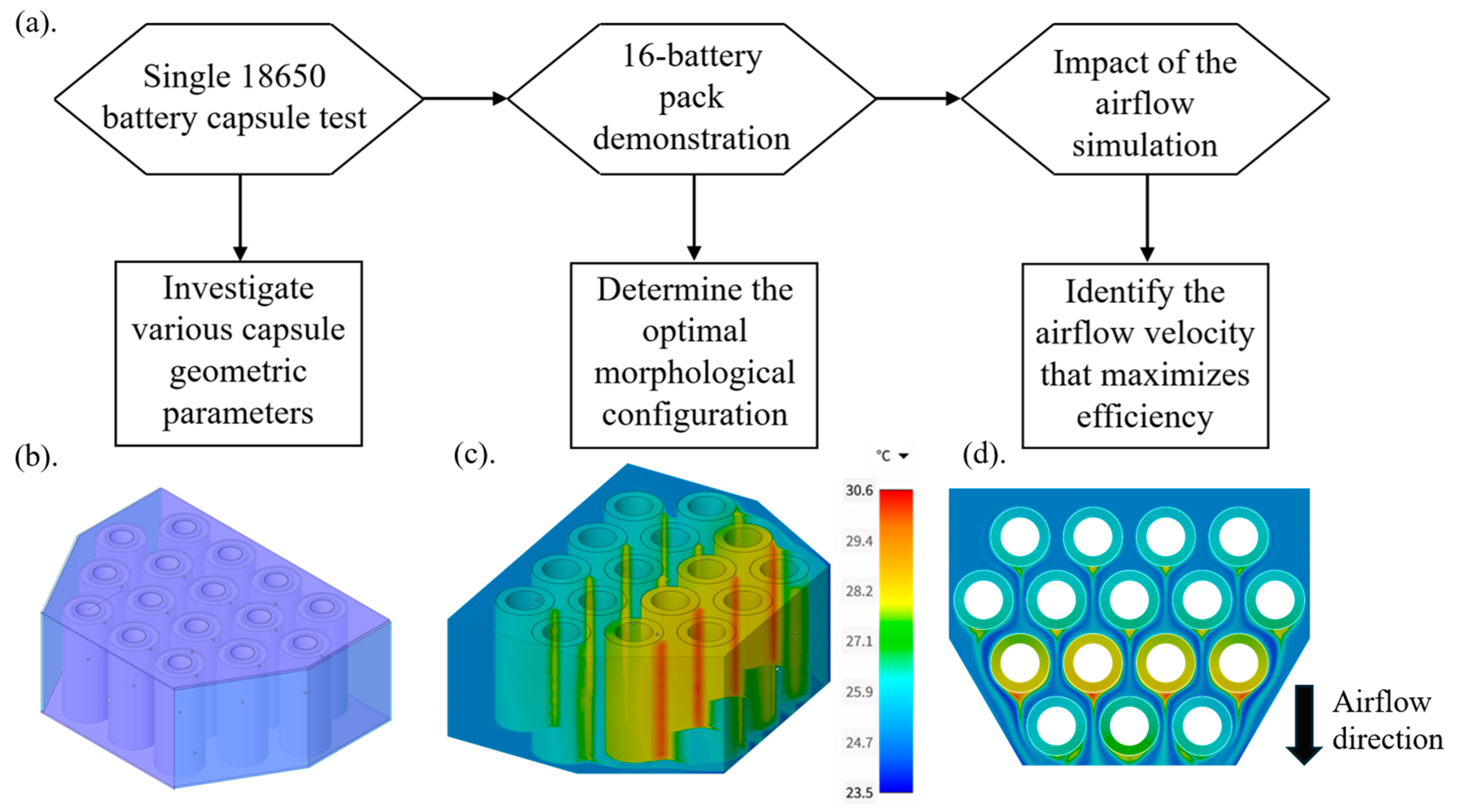
2. Design and Simulation

The analysis steps are presented in Figure 1a, outlining the progression from initial tests to comprehensive simulations. The study begins by evaluating a single 18650 battery capsule, analyzed through simulation and experimental methods to validate the computational approach [8]. This research centers on the thermal performance of a 16-battery pack, where each battery capsule is modeled as a uniform cylindrical structure. Key features explored include variations in battery arrangements, the influence of airflow inlet and outlet numbers, and the effect of airflow speed on heat dissipation. Simulations were conducted using Ansys Discovery 2024 R1 and Ansys Workbench 2024 R1 [30]. Determining optimal inlet and outlet numbers was a preliminary step to ensure adequate airflow and thermal management before finalizing the 16-battery pack design. The chosen arrangement, the trapezoidal (wide-base) configuration, was selected for its superior thermal performance.
Figure 1b provides a detailed schematic of the trapezoidal (wide-base) configuration arrangement, highlighting its structural design. The 3D-printed shell encloses the surrounding surfaces of the battery pack, ensuring a secure airflow area while enhancing the structural integrity. Battery positions within the arrangement are evenly distributed to ensure uniform heat transfer and airflow paths.
Simulation results are presented in Figure 1c,d, showing the temperature distribution across the 16-battery pack. Airflow direction remains consistent in both figures to facilitate comparative analysis. Figure 1c provides an isometric view of the 3D simulation results, while Figure 1d presents a top view of the same simulation. These visualizations are included for display purposes, with all results analyzed comprehensively Section 3.

2.1. Base Parameters Setting

To simulate the thermal behavior and airflow characteristics of the lithium-ion battery pack system, a steady-state computational fluid dynamics approach was employed using Ansys Discovery 2024 R1 and Ansys Workbench 2024 R1. The governing equations used in the simulations include the continuity equation, the Navier–Stokes equation for incompressible flow, and the energy conservation equation. These equations govern mass, momentum, and heat transfer processes, respectively, within the battery enclosure domain. The continuity equation ensures mass conservation:
· u = 0
where u is the velocity vector of the airflow.
The momentum conservation is described by the incompressible Navier–Stokes equation, accounting for pressure and viscous forces:
ρ u · u = p + μ 2 u
where ρ is the fluid density, p is the pressure, and μ is the dynamic viscosity of air.
Heat transfer within the domain was governed by the energy conservation equation, which includes both conductive and convective heat transport mechanisms:
ρ c p u · T = k 2 T + q
where T is the temperature, c p is the specific heat of the fluid, k is the thermal conductivity, and q is the volumetric heat generation term representing internal heat from the batteries. These governing equations (Equations (1)–(3)) were solved over a discretized 3D domain to compute the temperature and velocity distributions throughout the battery module.
To simplify the model while retaining physical relevance, several assumptions were adopted and are critically discussed here. The airflow was treated as steady, incompressible, and laminar. This assumption is justified by Reynolds number estimates across the studied velocity range (0–15 m/s), which remained below 2300 for the relevant inlet channel dimensions, supporting laminar flow behavior. Radiation effects were omitted due to the dominance of forced convection under drone-like conditions and the relatively low surface temperatures. Buoyancy forces induced by internal heat generation were also neglected, as the directional forced airflow overrode gravity-driven flow in the confined simulation domain. Additionally, thermal contact resistances at interfaces (e.g., battery–PCM or battery–air) were not modeled explicitly. While this may locally affect surface temperature gradients, the focus of this study is on comparative performance trends, which remain valid under this simplification.
The Reynolds number was calculated using inlet channel dimensions and airflow speeds ranging from 0 to 15 m/s. Under these conditions, the Reynolds number varied approximately from 450 to 2100, which is below the typical laminar–turbulent transition threshold (~2300). This supports the use of a laminar flow model throughout the studied velocity range. Additionally, buoyancy effects arising from internal heat generation were not considered. A comparison between Grashof and Reynolds numbers indicates that forced convection dominates over natural convection in this configuration, and thus buoyancy-driven flows have negligible influence on thermal transport.
The PCM was modeled using an effective specific heat approach with an ideal isothermal phase transition at 40 °C. This method simplifies numerical handling while capturing latent heat absorption during the melting phase. However, it does not account for non-idealities such as supercooling, subcooling, or transition kinetics. These effects can impact the transient thermal response and are acknowledged as limitations of the current model. Future work will explore more complex PCM behavior through either transient CFD simulations or experimental measurements. The PCM region was modeled using an effective specific heat capacity approach, in which the latent heat is distributed over a small temperature range centered around the melting point (40 °C). This steady-state approximation captures phase change effects without explicitly modeling enthalpy or time-dependent solid–liquid interface motion, which is appropriate for comparative evaluation under continuous operating conditions.
Boundary conditions were carefully defined to emulate real-world drone operating conditions. A velocity inlet was applied to the air entry points, with uniform flow velocity magnitudes ranging from 0 to 15 m/s and an inlet temperature fixed at 25 °C. At the outlet, a pressure boundary condition was applied at 0 Pa gauge pressure to represent atmospheric discharge, with fully developed flow behavior assumed. To quantify convective heat transfer within the air domain, the local convective heat transfer coefficient h was evaluated using the following relation:
h = q T s T
where q is the surface heat flux (1322.88 W/m2) [8], T s is the surface temperature of the battery cell, and T is the bulk fluid temperature.
This modeling approach treats each battery as a constant heat source, a common simplification in steady-state thermal analyses of battery systems. It facilitates a systematic comparison between different cooling strategies without introducing transient fluctuations or electrochemical variability. This assumption is particularly relevant in drone and portable electronics applications, where batteries often operate at consistent loads for extended durations, making predictable heat generation a practical modeling input. All solid–fluid interfaces, including the interior surfaces of the battery enclosure, were modeled with a no-slip condition to accurately capture velocity boundary layers and convective effects within confined flow channels.
The diamond shape in Figure 2a is an ideal symmetric configuration for this study, providing uniform airflow distribution and balanced geometric characteristics for thermal analysis. In Figure 2a, 5 inlets are positioned symmetrically along the top of the battery pack, and 5 outlets are located at corresponding points along the bottom. The initial diamond shape configuration involved a single inlet (Inlet 1) paired with a single outlet (outlet 1). Subsequently, to investigate the influence of inlet location on thermal performance, the outlet was fixed at outlet 1 while the inlet position was sequentially varied from Inlet 1 to Inlet 5. This process was reversed to examine the effect of outlet location, with the inlet fixed at Inlet 1 and the outlet position varied from outlet 1 to outlet 5. These sequential tests provided insights into the most effective inlet–outlet pairings for maximizing airflow efficiency and thermal dissipation.
Additionally, Figure 2b highlights the structural details of the battery sheath and the materials applied in the simulation. The sheath design is defined by 4 key radii: the inner sheath inside radius ( r i s , i ), the inner sheath outside radius ( r i s , o ), the outer sheath inside radius ( r o s , i ), and the outer sheath outside radius ( r o s , o ). The sheath layers are color-coded to indicate their respective materials in Figure 2c. The orange region represents the lithium-ion battery. The blue region corresponds to Markforged’s Onyx© filament, a composite material reinforced with chopped carbon fibers, characterized by high mechanical strength, stiffness, and compatibility with 3D printing technologies, ensuring the structural integrity of the battery pack. The red region signifies the nano-carbon-based PCM, chosen for its high thermal conductivity and latent heat storage capacity, which are essential for efficient thermal management.
This configuration ensures structural integrity and optimizes the airflow channel and thermal management performance. This study establishes a foundation for achieving a high-efficiency heat dissipation system in battery packs by combining a systematic analysis of inlet–outlet positioning and advanced material integration.

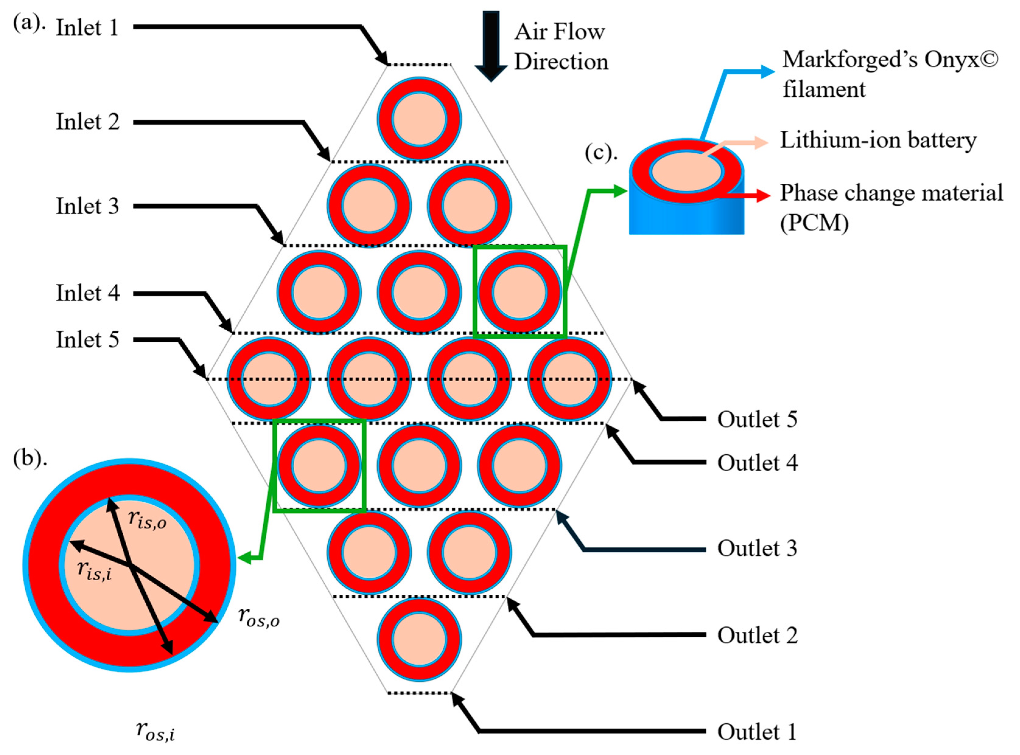
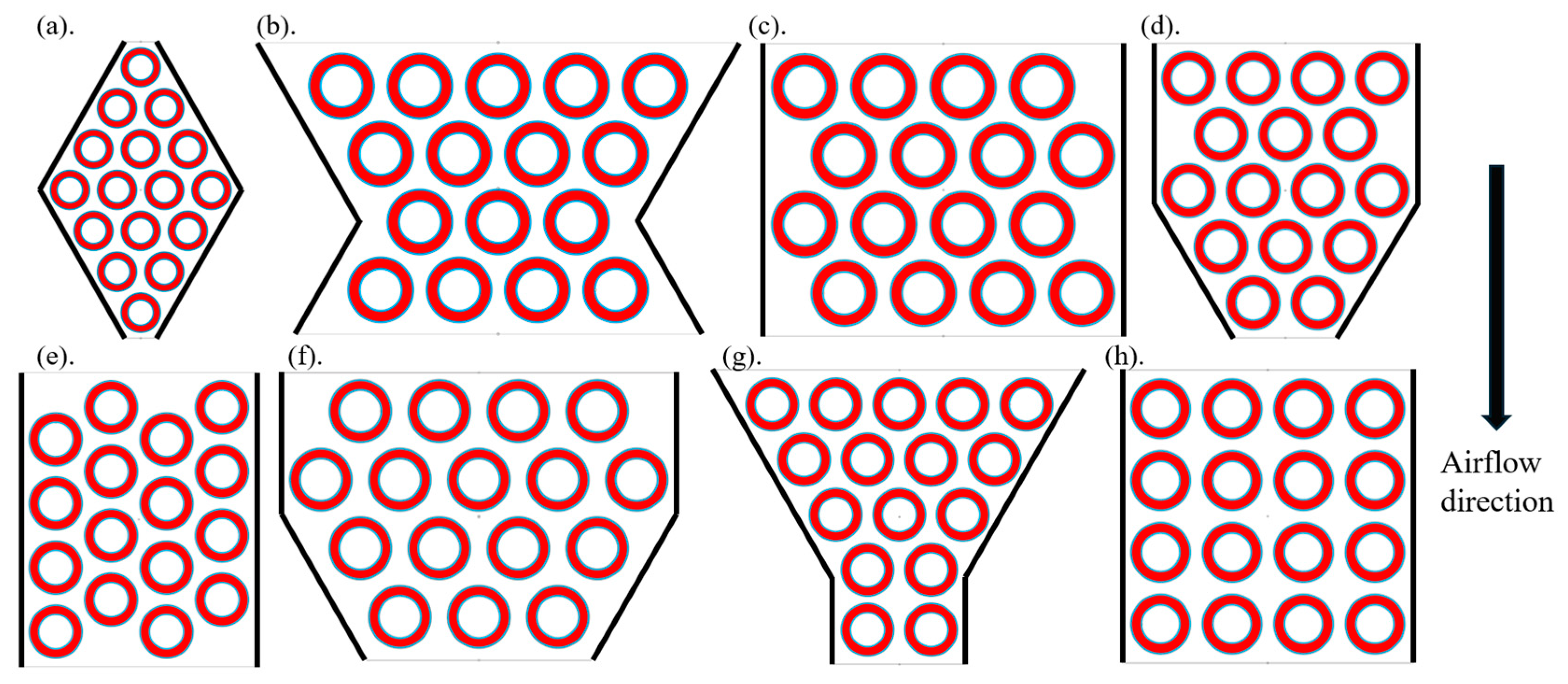
2.2. The 16-Battery Pack Configuration

The boundary conditions were defined as follows: velocity inlets with uniform flow ranging from 0 to 15 m/s and outlet pressure fixed at 0 Pa gauge pressure to simulate atmospheric discharge. Battery cell surfaces were assigned a constant surface heat flux of 1322.88 W/m2, and the initial temperature was set to 25 °C. All external battery walls were modeled as thermally insulated. A no-slip condition was applied at all solid–fluid interfaces. For a 16-battery pack, the initial configuration considered is the 4 × 4 square configuration (4444, Figure 3h). This configuration is one of the most common and straightforward designs due to its simplicity in alignment and space efficiency. All battery units in this setup are arranged in uniform rows and columns, providing a baseline for comparison with other configurations. The irregular rectangular configuration (4444-IR, Figure 3c) is generated by transforming this configuration and introducing a horizontal offset to each row. This staggered arrangement improves airflow distribution around each battery unit. Rotating the irregular rectangular configuration 90 degrees clockwise produces the inverted irregular rectangular configuration (4444-IIR, Figure 3e), which retains the staggered nature while providing an alternative flow pattern.
The diamond configuration (1234321, Figure 3a) is another critical design considered in this study. Its symmetrical shape is ideal for investigations requiring uniform geometric characteristics, making it valuable for symmetry-focused thermal and airflow research. This configuration allows for balanced heat dissipation and airflow paths, offering insights into performance under symmetric boundary conditions.
To achieve optimal cooling, staggered arrangements are prioritized. Staggering ensures airflow can reach all battery units more effectively, reducing thermal hotspots. It is well-known that heat tends to accumulate in the tail region of airflow setups as the air temperature rises while absorbing heat from upstream battery units. By addressing this, configurations with narrow tails were explored to increase airflow velocity in the tail region, mitigating heat accumulation.
The trapezoidal (wide-base) configuration (4543, Figure 3f) introduces a staggered arrangement with a broader base and a narrower tail. This configuration balances airflow distribution while leveraging a funnel-like effect at the tail to increase airflow speed, thus enhancing heat dissipation in the downstream region. It is also efficient in space utilization with its compact four-row design. Transforming this design to a trapezoidal (narrow-top) configuration (43432, Figure 3d) creates an even narrower tail, further accelerating airflow velocity at the downstream end and improving cooling performance.
An alternative transformation of the wide-base configuration is the trapezoidal (narrow-mid) configuration (5434, Figure 3b). This arrangement forms a funnel-like shape with a tail that is wider than that of a standard funnel configuration. This design balances airflow acceleration and uniform cooling across the battery pack.
Lastly, the funnel configuration (54322, Figure 3g) maximizes the funnel effect with a significantly narrow tail region that achieves the highest airflow velocity among the configurations. This setup is particularly effective in preventing thermal accumulation at the tail but sacrifices space efficiency due to its less compact design (Section 3).
Each configuration is selected and tested to evaluate its impact on the thermal heat dissipation performance. The variety of shapes allows for a comprehensive analysis of how geometric and staggered arrangements influence the cooling efficiency of a 16-battery pack under uniform operating conditions.

2.3. Ansys Thermal Simulation Settings

A mesh independence study was performed to ensure that the simulation results were not significantly influenced by the mesh density, thereby validating the accuracy and computational efficiency of the numerical model. This study evaluated the impact of mesh unit size on key thermal and airflow performance indicators, including maximum sheath temperature, heat flux distribution, and airflow velocity profiles. The initial coarse mesh had a unit size of 0.005 m , resulting in 37,003 mesh units. Subsequently, the mesh density was progressively refined to the finest mesh, with a unit size of 0.0005 m and 9,268,064 mesh units. A series of simulations were conducted across this range to identify the point at which further refinement produced negligible changes in the results. The final mesh chosen for this study had a unit size of 0.001 m , comprising 1,135,622 mesh units. This mesh density was selected to balance computational efficiency and result accuracy optimally. The variation in key performance metrics, specifically the maximum temperature between the selected mesh density and the finest mesh, was within 3%, rendering it negligible for this study. Figure 4 illustrates three computational mesh samples, highlighting the refinement of near-critical regions where steep gradients occur, including battery sheath surfaces, PCM layers, and airflow channels. The selected mesh ensures accurate thermal and airflow characteristics resolution while maintaining a manageable computational cost. This approach provides the reliability and robustness of the simulation results presented in this study, confirming that the outcomes are independent of the mesh resolution. The governing equations were discretized using the finite volume method within the Ansys Workbench platform. A second-order upwind scheme was applied for the convective terms to ensure numerical accuracy while reducing artificial diffusion. Pressure–velocity coupling was handled using the SIMPLE algorithm. These schemes offer stable and accurate resolution of velocity, pressure, and temperature fields, particularly in confined domains with mixed convection.
The simulation parameters listed in Table 1 define the thermal and physical properties used for the 16-battery pack analysis. The operating temperature range of the batteries is set between 10 °C and 55 °C, with an optimal operating temperature of 45 °C, ensuring the conditions align with practical operational limits. A uniform battery cell surface heat flux of 1322.88 W / m 2 , representing the heat generated during battery operation, is applied with an initial uniform temperature of 25 °C and an inlet airflow velocity that varies from 0 to 15 m / s .
For the PCM, a nano-carbon-based phase change material is utilized, and the melting temperature is set at 40 °C, with a latent heat of 173,400 J / k g , specific heat of 2890 J / k g · K , density of 800 k g / m 3 , and thermal conductivity of 16.6 W / m · K . These properties ensure the PCM’s capacity to absorb and regulate heat effectively. The sheath material is characterized by a thermal conductivity of 0.13 W / m · K , density of 1380 k g / m 3 , and specific heat of 1420 J / k g · K . The volume change in the PCM is negligible. These values reflect the thermal insulation and structural stability required to contain and manage heat transfer in the system.

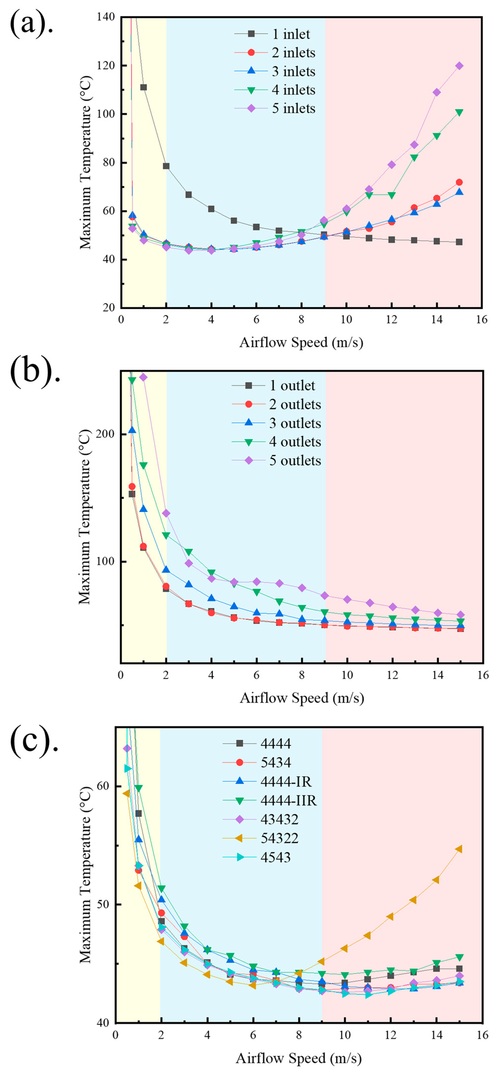
3. Simulation Results

In Figure 5a,b, the 5-inlet and 1-outlet configurations were established, and this study evaluated the thermal performance of seven battery pack arrangements under varying airflow conditions. The funnel configuration (54322) emerged as the most effective in the low-speed region, leveraging its narrow tail to accelerate airflow and enhance cooling. However, its performance deteriorates significantly in the high-speed region, where airflow instability undermines its heat dissipation capability. The rise in temperature in the high-speed region is attributed to the over-acceleration of the tail airflow caused by the increasing inlet airflow speed. In the funnel configuration, this phenomenon leads to excessive heat accumulation at the end units of the 16-battery pack, as the high-velocity airflow reduces the residence time of air over the battery cell surfaces, impairing effective heat transfer. Consequently, the end units experience localized overheating, compromising the overall thermal management efficiency of the configuration in the high-speed region.
While the present model does not resolve turbulence explicitly due to the laminar flow assumption, these observations suggest that flow detachment, thinning boundary layers, and adverse pressure gradients may develop at higher speeds, particularly in geometries with pronounced cross-sectional tapering such as the funnel configuration. At elevated inlet velocities, the airflow accelerates rapidly through the narrow tail region, which likely causes premature boundary layer separation and localized flow recirculation near the downstream battery cell surfaces. This flow behavior reduces the effective heat exchange area and shortens the convective residence time of the air, thereby diminishing the configuration’s cooling efficiency.
In addition, sharp pressure gradients between the upstream and downstream regions may lead to non-uniform flow redistribution across adjacent flow paths, amplifying hot spot formation. This is further exacerbated by the limited lateral diffusion of heat under confined, high-speed laminar flows. Such coupled thermal–fluid interactions could explain the significant performance drop of the funnel configuration in the high-speed regime.
This highlights the importance of balancing geometry-induced velocity enhancement with overall flow stability to avoid flow maldistribution and thermal concentration. Future work will incorporate transient simulations or turbulence-resolving models (e.g., Large Eddy Simulation, LES) to more thoroughly characterize these high-speed flow phenomena and validate these physical hypotheses.
Among all configurations, the trapezoidal (wide-base) configuration (4543) exhibited the most balanced performance across all speed regions in Figure 5c. In the low-speed region, its cooling performance was comparable to the funnel configuration, with only a marginally higher temperature. In the mid- and high-speed regions, it maintained thermal stability and kept the battery temperature within the optimal operating range of 45 °C. This versatility makes the trapezoidal (wide-base) configuration a robust choice for drone applications, where low-speed cooling is critical during startup and hovering phases, yet adequate thermal management at higher speeds remains essential.
The results highlight the importance of carefully selecting inlet, outlet, and battery arrangement configurations to achieve optimal thermal management. For drone operations, where low-speed airflow dominates, the trapezoidal (wide-base) configuration is recommended for its consistent performance and ability to maintain battery temperatures within safe operational limits under varying airflow conditions.

4. Conclusions

This study presents a comprehensive numerical investigation into the thermal management of lithium-ion battery packs through geometric optimization and material integration. Leveraging high-fidelity CFD simulations, the work evaluated seven distinct battery configurations and systematically varied inlet and outlet airflow conditions to assess cooling performance under low to moderate airflow regimes relevant to drone and compact electronics applications.
Among all configurations assessed, the trapezoidal wide-base (4543) arrangement exhibited the most balanced and efficient thermal behavior across all operating speeds. As illustrated in Figure 5c, this layout consistently achieved the lowest maximum battery temperatures while maintaining strong temperature uniformity throughout the pack. The staggered geometry of the wide-base arrangement effectively promotes airflow acceleration toward the tail region, mitigating thermal buildup in downstream cells—an issue commonly encountered in dense battery layouts.
In comparison to earlier works that emphasized flow redirection and turbulence management through external inlet–outlet tuning, such as those explored by Lee et al. [19], the present study introduces a passive geometric enhancement that achieves comparable airflow control internally without additional channeling. Similarly, while geometric principles have previously been analyzed concerning packing density and spacing uniformity, as discussed by Liu et al. [23], the current work advances this field by conducting a comprehensive shape-based optimization under unified simulation conditions, enabling a direct comparison of performance metrics across multiple geometries.
The integration of a nano-carbon-based PCM further reinforced thermal regulation by absorbing transient heat surges, extending the effective cooling duration to approximately 12.5 min. This dual strategy—combining structure-induced airflow manipulation with latent heat management—proves highly effective for space-constrained, energy-dense systems.
Although the findings are derived from high-fidelity numerical simulations, experimental validation remains essential. Prototype development for the trapezoidal (wide-base) configuration is currently underway to evaluate the thermal behavior under controlled airflow and load conditions. Additionally, previous experimental studies by our group involving single-cell modules have verified the validity of core assumptions such as constant surface heat flux and steady-state operation [8]. The upcoming experiments will extend this validation to full battery pack configurations under real-time operational scenarios.
Overall, this study offers a practical design framework for thermal performance optimization in lithium-ion battery systems. Future work will contain experimental validation and transient discharge analysis to extend and validate the simulation findings, enabling reliable deployment in real-world drone and portable electronics applications.

Author Contributions

X.Z.: Resources, Writing—original draft, Writing—review and editing; H.Z. (Hexiang Zhang): Resources, Writing—review and editing; A.A.: Resources, Writing—review and editing; M.S.: Resources, Writing—review and editing; J.D.K.: Resources, Writing—review and editing; H.Z. (Hengling Zhu): Resources; M.C.H.: Resources, Writing—review and editing; Y.Z.: Resources, Writing—review and editing, Project administration, Supervision. All authors have read and agreed to the published version of the manuscript.

Funding

This project is partially supported by the National Aeronautics and Space Administration Glenn Research Center Faculty Fellowship program and the National Science Foundation through grant number CBET-1941743.

Data Availability Statement

Data will be made available on request.

Conflicts of Interest

The authors declare that they have no known competing financial interests or personal relationships that could have appeared to influence the work reported in this paper.

References

  1. Amer, M.M.; Shouman, M.A.; Salem, M.S.; Kannan, A.M.; Hamed, A.M. Advances in thermal management systems for Li-Ion batteries: A review. Therm. Sci. Eng. Prog. 2024, 53, 102714. [Google Scholar] [CrossRef]
  2. Sorensen, A.; Urgikar, V.; Betz, J.E. A study of thermal runaway mechanisms in lithium-ion batteries and predictive numerical modeling techniques. Batteries 2024, 10, 116. [Google Scholar] [CrossRef]
  3. Ortiz, Y.; Paul Arévalo, E.; Peña, D.; Jurado, F. Recent advances in thermal management strategies for lithium-ion batteries: A comprehensive review. Batteries 2024, 10, 83. [Google Scholar] [CrossRef]
  4. E, J.; Yue, M.; Chen, J.; Zhu, H.; Deng, Y.; Zhu, Y.; Zhang, F.; Wen, M.; Zhang, B.; Kang, S. Effects of the different air cooling strategies on cooling performance of a lithium-ion battery module with baffle. Appl. Therm. Eng. 2018, 144, 231–241. [Google Scholar] [CrossRef]
  5. Shi, C.; Kim, S.H.; Warren, N.; Guo, N.; Zhang, X.; Wang, Y.; Willemsen, A.; López-Pernía, C.; Liu, P.; Kingon, A.I. Hierarchically micro- and nanostructured polymer via crystallinity alteration for sustainable environmental cooling. Langmuir 2024, 40, 20195–20203. [Google Scholar] [CrossRef]
  6. Li, X.; Sun, X.; Zhang, X.; Zheng, Y.; Minus, M.L. Ease-of-manufacture highly transparent thin polyvinyl alcohol aerogel. Sci. Rep. 2024, 14, 26276. [Google Scholar] [CrossRef]
  7. Wankhede, S.; Thorat, P.; Shisode, S.; Sonawane, S.; Wankhade, R. A study of different battery thermal management systems for battery pack cooling in electric vehicles. Heat Transf. 2022, 51, 7487–7539. [Google Scholar] [CrossRef]
  8. Zhang, X.; Liu, Y.; Halbig, M.; Singh, M.; Almansour, A.; Zheng, Y. Development and optimization of hybrid heat dissipation system for lithium-ion battery packs. Appl. Therm. Eng. 2024, 254, 123912. [Google Scholar] [CrossRef]
  9. Liu, X.; Zhang, X.; Chen, F.; Tian, Y.; Mu, Y.; Minus, M.L.; Zheng, Y. Accelerated water transportation phenomenon through a hydrophilic metal roll. ACS Appl. Eng. Mater. 2023, 1, 2745–2751. [Google Scholar] [CrossRef]
  10. Geng, S.; Zhang, X.; Liang, H.; Zheng, Y. Photonic-metamaterial-based, near-field-enhanced biosensing approach for early detection of lung and ovarian cancer. Photonics 2024, 11, 1020. [Google Scholar] [CrossRef]
  11. Wang, S.; Zhang, D.; Li, C.; Wang, J.; Zhang, J.; Cheng, Y.; Mei, W.; Cheng, S.; Qin, P.; Duan, Q. Numerical optimization for a phase change material based lithium-ion battery thermal management system. Appl. Therm. Eng. 2023, 225, 119839. [Google Scholar] [CrossRef]
  12. Zore, P.; Perera, N.; Lahr, J.; Hason, R. A novel thermal management system for cylindrical lithium-ion batteries using internal-external fin-enhanced phase change material. Appl. Therm. Eng. 2024, 238, 121985. [Google Scholar] [CrossRef]
  13. Kim, G.H.; Pesaran, A.; Spotnitz, R. A three-dimensional thermal abuse model for lithium-ion cells. J. Power Sources 2007, 170, 476–489. [Google Scholar] [CrossRef]
  14. Wang, T.; Tseng, K.J.; Zhao, J.; Wei, Z. Thermal investigation of lithium-ion battery module with different cell arrangement structures and forced air-cooling strategies. Appl. Energy 2014, 134, 229–238. [Google Scholar] [CrossRef]
  15. Karthik, C.A.; Kalita, P.; Cui, X.; Peng, X. Thermal management for prevention of failures of lithium ion battery packs in electric vehicles: A review and critical future aspects. Energy Storage 2020, 2, e137. [Google Scholar] [CrossRef]
  16. Zhao, G.; Wang, X.; Negnevitsky, M.; Zhang, H. A review of air-cooling battery thermal management systems for electric and hybrid electric vehicles. J. Power Sources 2021, 501, 230001. [Google Scholar] [CrossRef]
  17. Hamisi, C.M.; Gerutu, G.B.; Greyson, K.A.; Chombo, P.V. Thermal behavior of lithium-ion battery under variation of convective heat transfer coefficients, surrounding temperatures, and charging currents. J. Loss Prev. Process Ind. 2022, 80, 104922. [Google Scholar] [CrossRef]
  18. El Idi, M.M.; Karkri, M.; Tankari, M.A. A passive thermal management system of Li-ion batteries using PCM composites: Experimental and numerical investigations. Int. J. Heat Mass Transf. 2021, 169, 120894. [Google Scholar] [CrossRef]
  19. Zhang, S.B.; He, X.; Long, N.C.; Shen, Y.J.; Gao, Q. Improving the air-cooling performance for lithium-ion battery packs by changing the air flow pattern. Appl. Therm. Eng. 2023, 221, 119825. [Google Scholar] [CrossRef]
  20. Nazar, M.W.; Iqbal, N.; Ali, M.; Nazir, H.; Amjad, M.Z.B. Thermal management of Li-ion battery by using active and passive cooling method. J. Energy Storage 2023, 61, 106800. [Google Scholar] [CrossRef]
  21. Li, X.; Zhao, J.; Yuan, J.; Duan, J.; Liang, C. Simulation and analysis of air cooling configurations for a lithium-ion battery pack. J. Energy Storage 2021, 35, 102270. [Google Scholar] [CrossRef]
  22. Li, Y.; Du, Y.; Xu, T.; Wu, H.; Zhou, X.; Ling, Z.; Zhang, Z. Optimization of thermal management system for Li-ion batteries using phase change material. Appl. Therm. Eng. 2018, 131, 766–778. [Google Scholar] [CrossRef]
  23. Dubey, D.; Mishra, A.; Ghosh, S.; Reddy, M.V.; Pandey, R. Geometry-influenced cooling performance of lithium-ion battery. Appl. Therm. Eng. 2023, 230, 120723. [Google Scholar] [CrossRef]
  24. Fayaz, H.; Afzal, A.; Mohammed Samee, A.D.; Elahi, M.; Soudagar, M.; Akram, N.; Mujtaba, M.A.; Jilte, R.D.; Islam, M.T.; Ağbulut, Ü.; et al. Optimization of thermal and structural design in lithium-ion batteries to obtain energy efficient battery thermal management system (BTMS): A critical review. Arch. Comput. Methods Eng. 2022, 29, 129–194. [Google Scholar] [CrossRef]
  25. Mastan Vali, P.S.N.; Murali, G. Battery thermal management system on trapezoidal battery pack with liquid cooling system utilizing phase change material. J. Heat Mass Transf. 2024, 146, 011003. [Google Scholar] [CrossRef]
  26. Xu, C.; Zhang, H.; Fang, G. Review on thermal conductivity improvement of phase change materials with enhanced additives for thermal energy storage. J. Energy Storage 2022, 51, 104568. [Google Scholar] [CrossRef]
  27. Wang, H.; Guo, Y.; Ren, Y.; Yeboah, S.; Wang, J.; Long, F.; Zhang, Z.; Jiang, R. Investigation of the thermal management potential of phase change material for lithium-ion battery. Appl. Therm. Eng. 2024, 236, 121590. [Google Scholar] [CrossRef]
  28. Labat, M.; Virgone, J.; David, D.; Kuznik, F. Experimental assessment of a PCM to air heat exchanger storage system for building ventilation application. Appl. Therm. Eng. 2014, 66, 375–382. [Google Scholar] [CrossRef]
  29. Bianco, N.; Fragnito, A.; Iasiello, M.; Mauro, G.M. Multiscale analysis of a seasonal latent thermal energy storage with solar collectors for a single-family building. Therm. Sci. Eng. Prog. 2024, 50, 102538. [Google Scholar] [CrossRef]
  30. Ansys, Inc. Ansys Discovery 2024 R1 and Ansys Workbench 2024 R1: Multiphysics Simulation Software; Ansys: Canonsburg, PA, USA, 2024; Available online: https://www.ansys.com (accessed on 1 September 2024).
Figure 1. (a) Research steps. (b) Isotropic view of the trapezoidal (wide-base) configuration. (c) Isotropic view of the simulation result of the trapezoidal (wide-base) configuration. (d) Top view of the trapezoidal (wide-base) configuration and simulation result.
Energies 18 02234 g001
Figure 2. (a) Schematic representation of the diamond-shaped configuration illustrating inlet and outlet arrangements. (b) Definitions of battery sheath radii. (c) Material specifications utilized in the simulation.
Energies 18 02234 g002
Figure 3. All investigated configurations utilized identical unit battery sizes, with the boundaries of the airflow region delineated in black. (a) Diamond configuration (1234321). (b) Trapezoidal (narrow-mid) configuration (5434). (c) Irregular rectangular configuration (4444-IR). (d) Trapezoidal (narrow-top) configuration (43432). (e) Inverted irregular rectangular configuration (4444-IIR). (f) Trapezoidal (wide-base) configuration (4543). (g) Funnel configuration (54322). (h) Square configuration (4444). To accommodate all figures within a single layout, the battery capsules retain identical actual dimensions as used in the simulations, while varying zoom levels are applied for illustration purposes.
Energies 18 02234 g003
Figure 4. 3D mesh density analysis. (a) Isotropic view of the 4543 configuration with a mesh resolution size of 0.001 m. (b) Top view of the mesh resolution size of 0.005 m. (c) Top view of the mesh resolution size of 0.001 m. (d) Top view of the mesh resolution size of 0.0005 m. All figures share the same scale bar.
Energies 18 02234 g004
Figure 5. (a) Heat dissipation performance with varying inlet numbers with 1 outlet. (b) Heat dissipation performance with varying outlet numbers with 1 inlet. (c) Heat dissipation performance of battery pack configurations with 5 inlets and 1 outlet. The yellow region represents low-speed region (0–2 m/s), the blue region corresponds to med-speed region (2–9 m/s), and the red region indicates high-speed region (9–15 m/s).
Energies 18 02234 g005
Table 1. Thermal properties and operating settings of the simulation.
ParametersValueUnits
Battery operating temperature range10–55°C
Optimal operating temperature T i d e a l 45°C
Surface heat flux q g e n 1322.88 W / m 2
Initial temperature T i 25°C
Inlet velocity V 0–15 m / s
PCM melting temperature T P C M 40°C
PCM latent heat H 173,400 J / k g
PCM specific heat c p 2890 J / k g · K
PCM density ρ P C M 800 k g / m 3
PCM thermal conductivity k P C M 16.6 W / m · K
Sheath thermal conductivity k s 0.13 W / m · K
Sheath density ρ s 1380 k g / m 3
Sheath specific heat c p s 1420 J / k g · K
Inner sheath inside radius r i s , i 9 m m
Inner sheath outside radius r i s , o 9.9 m m
Outer sheath inside radius r o s , i 14 m m
Outer sheath outside radius r o s , o 14.9 m m
Disclaimer/Publisher’s Note: The statements, opinions and data contained in all publications are solely those of the individual author(s) and contributor(s) and not of MDPI and/or the editor(s). MDPI and/or the editor(s) disclaim responsibility for any injury to people or property resulting from any ideas, methods, instructions or products referred to in the content.

