Abstract
The electrolytic capacitor-less PMSM drive system presents complex nonlinear characteristics. Since electrolytic capacitor-less systems exhibit low inertia due to the absence of energy storage components, traditional controllers struggle to achieve the dynamic optimization of phase and amplitude margins, resulting in power transmission mismatches that trigger DC bus voltage surges. This severely limits the dynamic response capability and reliable operation of the system across full operating conditions, leading to an insufficient wide-speed-range performance and disturbance rejection. This study investigates the stable operation mechanism under intermittent working conditions by analyzing DC bus voltage transient characteristics. It optimizes control parameters for stable intermittent operations and establishes a neural network-based adaptive controller model. By modeling the correlation between hardware parameters and control parameters in drive systems under frequent start–stop conditions, this research achieves dynamic controllability of the controller during intermittent operations. This approach enhances the computational accuracy of the drive system control model, ultimately improving system-wide operational reliability and adaptability. Experimental validation confirms the effectiveness of this approach, showing significant reliability improvements in capacitor-less variable-frequency speed-control systems. Key innovations include: (1) BP neural network integration for dynamic parameter optimization, (2) impulse voltage suppression through adaptive control matching, and (3) enhanced transient response via machine learning-enhanced speed regulation. The test results demonstrate a 63% reduction in bus voltage fluctuations and 35% improvement in load transition responses compared to conventional PID-based systems, proving the strategy’s practical viability for industrial drive applications.
1. Introduction
A frequency-conversion drive system without an electrolytic capacitor replaces the large-capacity electrolytic capacitor on a DC bus with a traditional frequency-conversion drive system [1]. Compared with the traditional frequency-conversion drive system, this design not only reduces the weight and volume of the system, but also significantly improves the response speed and efficiency. The use of thin-film capacitance reduces the possible failure of electrolytic capacitance at a high temperature and long time operation, thus improving the stability, realizing the high power factor and life of the whole drive system [1,2]. The research on the low-power electrolytic capacitor-frequency-conversion drive system mainly focuses on the single-phase uncontrolled rectifier electrolytic capacitor-frequency-conversion drive system [3,4]. The research mainly focuses on improving the system’s input power factor and improving the tracking effect of the power controller [5,6]. A high PF is achieved by adopting the power control strategy, where the power strategy controls the relationship between the input power and the output power of the inverter [7,8,9]. Figure 1 shows a single-phase input frequency-conversion drive system without an electrolytic capacitor.
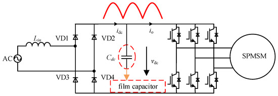
Figure 1.
Single-phase input frequency-conversion drive system without an electrolytic capacitor.
The current research primarily concentrates on how to reduce the DC bus capacitance and improve the input power factor of the system. Figure 2 shows a single-phase no-DC bus electrolytic capacitor-frequency-conversion drive control diagram based on different controls.
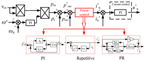
Figure 2.
The single-phase frequency-conversion drive control system without a DC bus electrolytic capacitor based on different controllers.
However, there are few studies on the dynamic performance and stability of the system. Because there is no large capacity energy storage element on the DC bus, the transient impulse voltage is generated when the load and speed change. The DC bus voltage is the pulsating DC voltage, and the motor control is in the overmodulation state when the voltage is in the trough [10,11,12]. The impulse voltage and motor overmodulation operation both threaten the stability of the system. The electrolytic capacitor-less motor drive system exhibits multi-physics coupling and strong nonlinear time-varying characteristics, requiring a dynamic reconstruction of state equations based on motor power demand characteristics [13,14,15]. Furthermore, conventional control models fail to achieve the dynamic optimization of phase/amplitude margins, resulting in dynamic power transmission mismatches that induce DC bus voltage surges. This fundamentally restricts the system’s dynamic response capability and operational reliability across full working conditions [15,16,17].
The inertia of the variable-frequency drive system reflects the ability of the system to prevent a sudden voltage change. In order to further meet the requirements of the load cutting stability of the variable-frequency drive system without an electrolytic capacitor, some scholars proposed a virtual inertia control strategy [18,19]. Subsequent studies developed a small-signal model of virtual capacitor control, where the dynamic transfer function between the output current and voltage of the DC bus was derived, thus enhancing the DC bus voltage dynamic response capability [20,21,22].
The virtual inertia mechanism mitigates bus voltage fluctuations through controlled system inertia augmentation via virtual capacitance. This provides critical time buffers for power regulation and balance restoration during load transients. However, this stability enhancement inherently compromises the system’s response speed, creating a fundamental conflict with high dynamic performance requirements [23,24]. The fixed-parameter nature of conventional virtual inertia implementations proves particularly inadequate for applications demanding wide-range operational adaptability.
2. Transient Stable-Operation Control-Parameter Dataset Creation
Control challenges become more pronounced when considering the inherent complexity of electrolytic capacitor-less drive systems as strongly nonlinear multivariable systems. The conventional PID explicit modeling process method makes the offline non-electrolytic capacitor variable-frequency drive system equivalent linear. Moreover, the fixed control parameters in such methodologies fail to adapt to instantaneous optimal operational requirements, consequently impeding precise switching device regulation for achieving energy flow optimization. In addition, when the system is unloaded, the instantaneous impulse voltage generated is still the main threat to the system’s stability [25,26,27].
The frequency-conversion drive system does not have enough inertia to overcome the instantaneous impact voltage in the load and speed mutation. In addition, since the system is a single-phase diode rectification, the power transmission is unidirectional, and the accumulation of energy on the DC bus during unloading poses a threat to the system’s stability [26]. In the DC bus voltage control, the virtual capacitance is used to enhance the inertia and suppress the DC bus voltage mutation [28,29,30]. The virtual inertia equation based on voltage–current droop control is as follows:
where Iset is the reference of the DC bus output current, p*inv is the reference of input power, Vdc. is the DC bus voltage amplitude, io is the DC bus voltage amplitude, is the DC bus reference voltage, and Cv0 is the virtual capacitance value. Figure 3 is the virtual capacitor control block diagram based on DC bus voltage control.

Figure 3.
Virtual capacitor control block diagram based on DC bus voltage control.
The non-electrolytic capacitance system has a very low inertia due to the lack of bus energy storage. In the process of the millisecond load mutation of the system, the harmonic frequency spectrum is dynamically expanded, causing harmonic resonance and even system instability. The existing improvement scheme (such as virtual inertia control) improves the steady-state performance at the expense of the dynamic response, which is difficult to meet the millisecond regulation requirements. Equation (2) is the velocity open-loop transfer function:
The traditional d-q-axis decoupling model ignores the influence of the system’s voltage–current–load–power. The system presents high-dimensional characteristics under electromechanical–electromagnetic thermal field strong coupling (dimension > 30). The existing model finds it difficult to accurately characterize the nonlinear dynamic response of the system bus voltage in the 0.1–10 kHz frequency band, which restricts the realization accuracy of the control. The fixed-phase angle/amplitude margin produces the state observation error, resulting in a power dynamic mismatch and an avalanche of bus voltage drop or impact (>50%) values, which seriously restricts the dynamic response ability and reliable operation of the system in the whole working condition. The steady-state algorithm based on virtual impedance is to sacrifice the fixed response speed so that the motor feedback energy can be used in other parts of the system, thus alleviating the problem of bus voltage shock.
The steady-state PI control parameters are not suitable for the transient control of the system, and the optimal control parameters of instantaneous operation need to be established urgently. Therefore, based on the dynamic transfer function of the control loop and a large number of simulation and experimental debugging practices during the cut-load operation, this paper determines the optimal PI parameter of the speed loop during the transient operation of the system. The optimal parameter can adaptively determine the response speed and reduce the voltage impact of the bus with the least sacrifice.
Through a large number of cutting-load experiments, we can obtain the best parameter curves of , under a dynamic cut load, and the characteristics are similar. Figure 4 takes the optimal parameter curve of the rotational speed ring as an example:
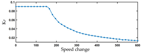
Figure 4.
Plot of change under different cutting conditions.
In order to realize the stable work of the full power section of the system, different cutting load conditions of different initial speeds and an initial speed are collected for testing and debugging, and the optimal control parameters of the instantaneous stable running speed ring , datasets are created. The initial speed of the selected dataset is 1500, as shown in Table 1.

Table 1.
Dataset at an initial speed of 1500 rpm.
The dataset of rotational speed-ring PI parameters in the full power segment is shown in Figure 5.
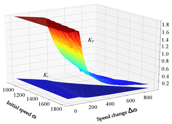
Figure 5.
The PI parameter stable dataset of the speed loop.
3. Construction of the Neural Network-Based Adaptive Controller Model
Compared to vector control modeling approaches, neural networks demonstrate distinct advantages in addressing challenges such as multivariable coupling, nonlinear characteristics, and external stochastic disturbances.
Based on the controller dynamic control-parameter dataset, the adaptive controller model based on the neural network is constructed to fit the relationship between the hardware parameters and control parameters of the driving system under frequent start and stop conditions, so as to improve the controllability and sensitivity of the controller under random load disturbance.
Therefore, on the basis of the established rotation speed for the PI parameter dataset, the number of layers is 3; the rotational speed, , and transition signals, , are selected as the input layer of the neural network; and and serve as the output layer of the network. The control diagram of the optimal control parameters of the speed ring based on the BP neural network is shown in Figure 6.
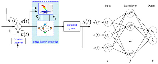
Figure 6.
The neural network-based adaptive controller.
During neural network training, sample data are typically divided into a training set, validation set, and test set. The training set is used for training and optimizing model parameters through backpropagation and gradient descent. By learning the mapping the relationship between the inputs and outputs in the dataset, it adjusts the network weights and biases to minimize the loss function. The validation set evaluates the model’s performance during training by computing the loss function and evaluation metrics. The test set assesses the final model’s performance to ensure strong generalization capabilities.
Before feeding the data into the neural network model, raw data must undergo preprocessing and transformations to improve training efficiency, mitigate data-related issues during training, and enhance model stability and accuracy. After completing the data preprocessing, the training process for a BP neural network integrated with a PI controller can be summarized in the following steps:
- (1)
- Network architecture determination and initialization define the neural network structure; the number of layers is 3. Initialize connection weights and biases between neurons and select an appropriate learning rate to ensure training stability and convergence.
- (2)
- Forward propagation calculation performs forward propagation based on the predefined network architecture. Using activation functions, compute the inputs and outputs of hidden-layer neurons sequentially, ultimately deriving the input and output results of the output layer. The purpose of forward propagation is to obtain predictions and prepare for subsequent error calculations.
- (3)
- Error calculation and correction compute the loss function value based on the error between the neural network’s output and the desired PI controller parameters. Using backpropagation, reverse the error layer by layer to calculate gradients for each layer. Adjust weights and biases to reduce the output errors and optimize the network’s performance.
- (4)
- Model evaluation and architecture selection evaluate and select the trained network to ensure it effectively approximates the required control performance.
Through these steps, the BP neural network can successfully train PI controller parameters suitable for speed-control loops, thereby improving system control precision and stability.
In order to obtain a strong and stable DC bus voltage, we propose an adaptive controller strategy based on a neural network. The DC bus voltage overshoot suppression strategy is applied to the network-side high-power-factor electrolytic capacitor-less drive system, and the overall control block diagram of the system is shown in Figure 7.
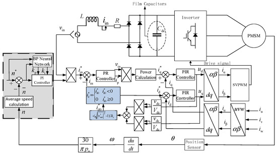
Figure 7.
The block diagram of the high stability of the adaptive controller based on a neural network for an electrolysis-free-capacitor motor drive system.
4. Simulation and Experimental Results
This study conducted simulation experiments on the proposed BP neural network-based parameter self-tuning speed-loop design. The simulations encompassed the training and evaluation of the BP neural network. After determining the network architecture, the trained BP neural network was integrated with the speed loop to perform a comparative analysis of DC bus voltage stability in the electrolytic capacitor-less system before and after implementing the PI parameter self-tuning strategy.
Firstly, the BP neural network was trained and evaluated in simulation software. The dataset was partitioned into 70% for training, 15% for validation, and 15% for testing. The neural network training results are shown in Figure 8, Figure 9 and Figure 10.
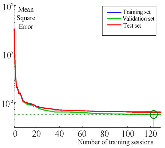
Figure 8.
Number of training sessions and mean squared error.
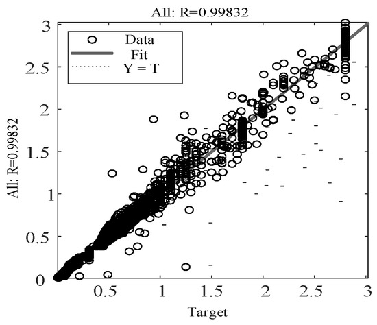
Figure 9.
Goodness of fit.
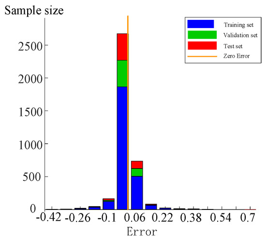
Figure 10.
Error distribution.
Figure 8 demonstrates that after 130 iterations, the mean squared error (MSE) of the neural network decreased below 0.003 and stabilized, at which point the training process was terminated. Figure 8 reveals that the R2 value of the samples reaches 0.998, approaching the ideal value of 1 and satisfying the training requirements.
Furthermore, Figure 10 illustrates that the error distribution is predominantly concentrated within the near-zero error range, validating the suitability of the neural network architecture.
4.1. Simulation Results
The neural network-based adaptive controller achieves high-precision dynamic control of the speed loop. To simulate the impact of intermittent operating conditions on the system’s stability, a sudden speed reference change from 1500 rpm to 1000 rpm was implemented at t = 1 s. The simulation parameters of the PMSM are shown in Table 2.

Table 2.
Parameters of the PMSM.
A sudden speed reference change from 1500 rpm to 1000 rpm was implemented at t = 1 s, Te = 2.4 N·m. Figure 10 and Figure 11 present the simulated DC bus voltage responses to motor speed variations under conventional PI control and instantaneous optimal speed-loop control strategies, respectively. Figure 11 and Figure 12 present the simulation results of motor speed transients under conventional PI control. There is a huge impact on the DC bus voltage of about 900 V under the traditional PI control, which causes serious damage to the power device. Since the bus bar voltage fluctuation should be strictly controlled at ±15%, the huge impact on the DC bus voltage affects the reliability of the system.
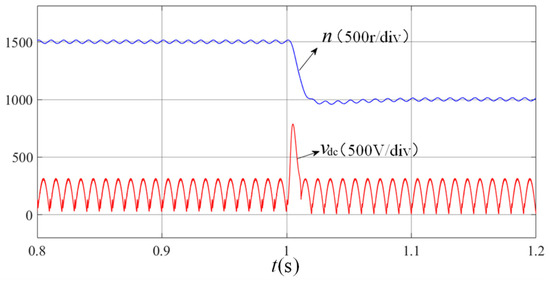
Figure 11.
DC bus voltage and speed based on traditional PI control.
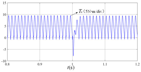
Figure 12.
Motor electromagnetic torque waveform under PI control.
A sudden speed reference change from 1500 rpm to 1000 rpm was implemented at t = 1 s, Te = 2.4 N·m. The simulation results of the adaptive controller under the same operating conditions are shown in Figure 13 and Figure 14.
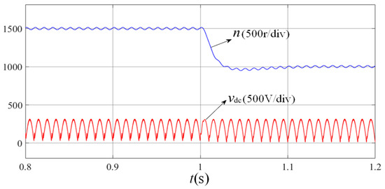
Figure 13.
DC bus voltage and speed based on the BP neural network.
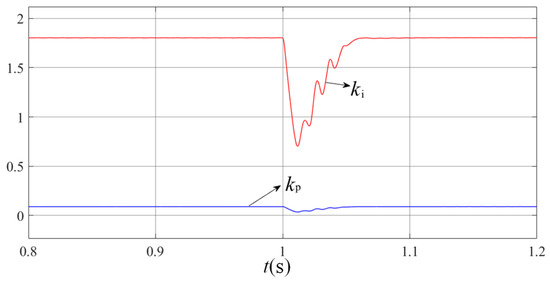
Figure 14.
Adaptive adjustment of rotational speed-ring PI parameters.
Figure 13 and Figure 14 present the simulation results under identical operating conditions with the implementation of the BP neural network-based PI control, revealing a 63% reduction in DC bus voltage fluctuations compared to conventional methods. The system demonstrates enhanced stability through a comparative analysis. This outcome confirms the strategy’s efficacy in suppressing transient voltage surges while improving the system’s dynamic stability and operational reliability.
As demonstrated in Figure 13, the system employing instantaneous optimal speed-loop control parameters successfully eliminates DC bus voltage surges induced by abrupt speed command changes at t = 1 s, achieving this with only a minimal response speed penalty of approximately 10 ms. Figure 14 reveals that the BP neural network-based speed loop exhibits rapid parameter adaptation: upon detecting speed command variations, it dynamically adjusts its Kp and Ki coefficients to accommodate system transients, then autonomously reverts to steady-state optimal PI parameters once stability is restored. Furthermore, Figure 15 confirms that the instantaneous optimal control strategy effectively suppresses electromagnetic torque pulsations, ensuring continuous motor operation and enhanced system stability. In Figure 16, the input current of the non-electrolytic capacitance system under the control of the neural network is close to sinusoidal, the measured power factor is 0.993, and the system has a high power factor. Collectively, these experimental results validate that the proposed control strategy not only mitigates DC bus voltage overshoots during motor speed transitions, but also significantly enhances the system’s operational stability and reliability.
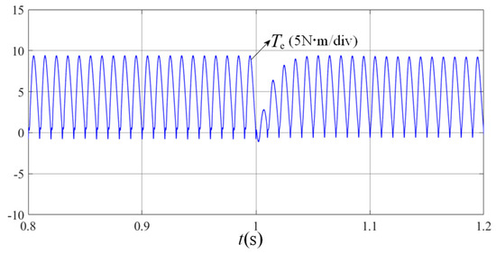
Figure 15.
Waveform of electromagnetic torque based on the BP neural network.
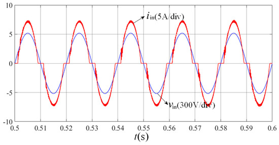
Figure 16.
Input voltage/input current waveforms under the control of the neural network.
4.2. Experimental Verification
The hardware of the experimental platform consists of an AC power supply, EXTECH6210, a three-phase-inverter power driver board, a DSP chip for motor control, and a surface-mounted permanent magnet synchronous motor. To simulate real-world power consumption scenarios, such as household appliance operation, the system was configured with a 50 Hz AC voltage source as the input for the electrolytic capacitor-less system. Aligned with low-cost and high-integration development trends, the rectifier circuit was implemented using four uncontrolled diodes. A low-capacitance film capacitor (10 μF) was adopted for the DC bus. To further enhance hardware safety and mitigate electromagnetic interference (EMI), circuit breakers and isolated transformers were integrated between circuit stages. The motor load was driven by a magnetic powder brake to simulate dynamic loading conditions. The block diagram of the overall hardware composition of the control system is shown in Figure 17. The parameters of the power driver board are shown in Table 3.
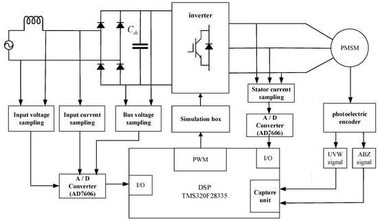
Figure 17.
The block diagram of the overall hardware composition of the control system.

Table 3.
Power driver board parameters.
Set the speed of the permanent magnet synchronous motor to 1200 rpm, and conduct the experiments when the motor is in the no-load mode and when the load torque is 1 N·m. The experimental results when the motor is in the no-load mode and the motor power is 125 W are shown in Figure 18 and Figure 19.
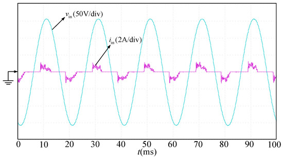
Figure 18.
Input voltage and input current waveforms at no load.
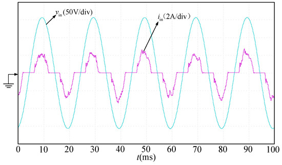
Figure 19.
Input voltage and input current waveforms at 125 W.
As can be seen from Figure 18 and Figure 19, when the motor is running at no load, the input power factor of the system is small because the active power of the system is small and the reactive power on the capacitor inductor is relatively large. When the motor is loaded, the active power increases and the input current sinusoidal degree becomes higher.
By changing the motor load torque to rated torque 2.4 N·m, the experimental waveform can be obtained when the motor power is 300 W, as shown in Figure 20, Figure 21 and Figure 22. Figure 20 and Figure 21 show that at the rated torque, the DC bus voltage fluctuates at 100 Hz and the diode conduction angle increases. At this time, due to the high active power ratio, the input current loop is well controlled, the input current is close to sinusoidal, and the average power factor of the system is 0.955, with the highest value reaching 0.991. It can be seen from Figure 22 that the motor stator current is more sinusoidal after using high-power-factor control. The DC bus voltage overshoot-suppression strategy is validated in this high-power-factor electrolytic capacitor-less drive system.
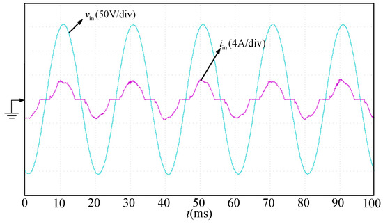
Figure 20.
Input voltage and input current waveforms at 300 W.
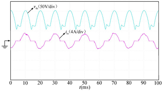
Figure 21.
Bus voltage and input current waveforms at 300 W.
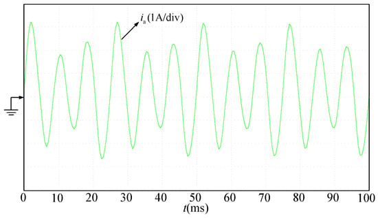
Figure 22.
Stator current of A-phase at 300 W.
Set the load torque of the motor to the rated torque of 2.4 N·m, switch the motor speed from 1500 rpm to 900 rpm, and obtain the experimental waveform as shown in Figure 23. It can be seen from Figure 23, since the front end of the electrolytic capacitance-frequency-conversion drive system is a single-phase uncontrolled rectifier, the energy flows unidirectionally from the input side to the motor side, and when the motor decelerates, the DC bus voltage has a voltage surge that is 100 V higher than the input voltage amplitude, which is not conducive to the reliability of the system.
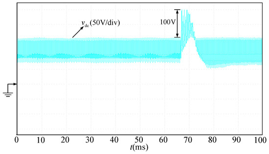
Figure 23.
DC bus voltage waveform during motor deceleration.
Using the neural network-based adaptive controller strategy, the experimental waveforms obtained after setting the motor speed ranging from 1500 rpm to 900 rpm are shown in Figure 24.
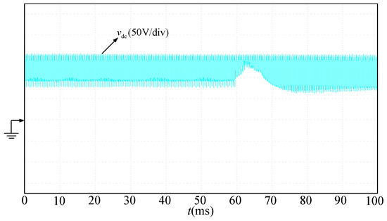
Figure 24.
DC bus voltage waveform during motor deceleration after adding the overshoot suppression control algorithm.
From the experimental results shown in Figure 24, after using the DC bus voltage overshoot suppression strategy proposed in this paper, the inrush voltage at the bus is significantly suppressed and the bus voltage does not exceed the input voltage amplitude, which protects the power devices of the system and improves the reliability of the system. The experiments verify the effectiveness of the control strategy. Table 4 shows the comparison of the decoupling control representative algorithm of the non-electrolytic capacitor-frequency-conversion drive system.

Table 4.
Comparison of the decoupling control representative algorithm of the non-electrolytic capacitor-frequency-conversion drive system.
5. Conclusions and Discussion
The permanent magnet motor drive system without electrolytic capacitors suffers from limitations in its wide-speed-range operation and disturbance rejection capability due to its low system inertia. To address these challenges, this study focuses on the following key research directions: according to the characteristics of bus voltage during sudden loads and power fluctuations, the stable operation mechanism, weak points of the control strategy, and general law of energy flow of the multi-mode process system are revealed. Based on the voltage fluctuation characteristics of the DC bus, the instantaneous and stable operation control parameters were debug optimized and the dynamic control-parameter dataset of the controller was created. An adaptive controller model based on a neural network was constructed to fit the relationship between the hardware parameters of the drive system and the control parameters under frequent start–stop conditions, so as to improve the controllability and sensitivity of the controller under random load disturbances. By establishing the simulation model and the experimental platform, the feasibility of the control strategy of the frequency-conversion speed-control system without an electrolytic capacitor is verified. The test results demonstrate a 63% reduction in bus voltage fluctuations and 35% improvement in the load transition response compared to conventional PID-based systems. The proposed strategy significantly enhances the controller’s controllability and responsiveness during random load disturbances, while enabling the stable operation of the single-phase input electrolytic capacitor-less motor drive system under dynamic operating conditions.
The proposed method relies on a specialized dataset for optimal control-parameter matching, which may limit its generalizability to different types of PMSM systems or applications. The authors will continue to study the key technologies of dimensional reduction and decoupling, high-precision dynamic modeling, dynamic response, and stability energy optimization. A nonlinear regression model of the non-electrolytic capacitor drive system will be constructed to create an observation–control data pair sample with a stable operation result during the whole working condition domain to improve the acquisition efficiency of typical scale datasets. We also aim to explore the robust optimization of a cross-scene random-domain perturbation learning model based on the security constraints.
Author Contributions
Conceptualization, D.B.; methodology, D.B.; software, H.S.; validation, H.Y., W.D. and Y.G.; formal analysis, Z.S.; investigation, W.D.; writing—original draft preparation, T.G.; supervision, Z.S.; project administration, T.G.; funding acquisition, D.B. All authors have read and agreed to the published version of the manuscript.
Funding
This research was funded by the National Natural Science Foundation (Grant No: 52107202), Shenzhen Science and Technology Plan Project (Grant No: JCYJ20210324100803008 and RCBS20210706092213010), and the Shenzhen Polytechnic University Research Fund Grant No: 6025310053K.
Data Availability Statement
All data included in this study are available upon request by contact with the corresponding authors.
Conflicts of Interest
Author Danyang Bao was employed by the company Hengxiang Technology Co., Ltd.. The remaining authors declare that the research was conducted in the absence of any commercial or financial relationships that could be construed as a potential conflict of interest.
References
- Kim, M.-N.; Noh, Y.-S.; Kim, J.-G.; Jung, Y.-C.; Won, C.Y. Active power decoupling using bi-directional resonant converter for flyback inverter without electrolytic capacitor of PV AC module system. In Proceedings of the 2013 International Conference on Electrical Machines and Systems (ICEMS), Busan, Republic of Korea, 26–29 October 2013; pp. 351–356. [Google Scholar]
- Ziogas, P.D.; Kang, Y.G.; Stefanovic, V.R. Rectifier-Inverter Frequency Changers with Suppressed DC Link Components. IEEE Trans. Ind. Appl. 1986, IA-22, 1027–1036. [Google Scholar] [CrossRef]
- Xiong, H.; Li, X.H. Study on Variable Frequency Operation of Single-phase Permanent-magnet Synchronous Motor. Small Spec. Electr. Mach. 2002, 23–25. [Google Scholar]
- Pan, X.; Rathore, A.K. Electrolytic capacitorless current-fed singlephase pulsating DC link inverter. IEEE Trans. Veh. Technol. 2018, 67, 3900–3908. [Google Scholar] [CrossRef]
- Vogelsberger, M.A.; Wiesinger, T.; Ertl, H. Life-Cycle Monitoring and Voltage-Managing Unit for DC-Link Electrolytic Capacitors in PWM Converters. IEEE Trans. Power Electron. 2011, 26, 493–503. [Google Scholar] [CrossRef]
- Chen, W.; Ron Hui, S.S. Elimination of an Electrolytic Capacitor in AC/DC Light-Emitting Diode (LED) Driver with High Input Power Factor and Constant Output Current. IEEE Trans. Power Electron. 2012, 27, 1598–1607. [Google Scholar] [CrossRef]
- Seo, G.S.; Lee, K.C.; Cho, B.H. A New DC Anti-Islanding Technique of Electrolytic Capacitor-Less Photovoltaic Interface in DC Distribution Systems. IEEE Trans. Power Electron. 2012, 28, 1632–1641. [Google Scholar] [CrossRef]
- Li, C.; Deng, Y.; Peng, H.; Li, W.; He, X.; Wang, Y. Partial Power Conversion Device Without Large Electrolytic Capacitors for Power Flow Control and Voltage Compensation. IEEE Trans. Power Electron. 2012, 27, 4847–4857. [Google Scholar] [CrossRef]
- Ma, H.; Lai, J.S.; Feng, Q.; Yu, W.; Zheng, C.; Zhao, Z. A Novel Valley-Fill SEPIC-Derived Power Supply Without Electrolytic Capacitor for LED Lighting Application. IEEE Trans. Power Electron. 2012, 27, 3057–3071. [Google Scholar] [CrossRef]
- Ando, I.; Shibata, J.; Haga, H.; Ohishi, K. Long life ups based on active filter and flywheel without electrolytic capacitor. In Proceedings of the 2007 European Conference on Power Electronics and Applications, Aalborg, Denmark, 2–5 September 2007; pp. 1–10. [Google Scholar]
- Bai, Y. Research on Electrolytic Capacitor-Less Control Strategy for Air-Conditioning Permanent Magnet Compressor Drives. Master’s Thesis, Harbin Institute of Technology, Harbin, China, 2020. [Google Scholar]
- Takahashi, I.; Haga, H. Power factor improvement of single-phase diode rectifier by fast field-weakening of inverter driven IPM motor. In Proceedings of the 4th IEEE International Conference on Power Electronics and Drive Systems, Proceedings, Denpasar, Indonesia, 25–25 October 2001; IEEE: Piscataway, NJ, USA, 2001. [Google Scholar]
- Hatlehol, M.; Park, D.; Zadeh, M.K. A Modified Sliding Mode Controller for Active Stabilization of DC Microgrids with Constant Power Load. In Proceedings of the IECON 2019—45th Annual Conference of the IEEE Industrial Electronics Society, Lisbon, Portugal, 14–17 October 2019; IEEE: Piscataway, NJ, USA, 2019. [Google Scholar]
- Cspedes, M.; Beechner, T.; Xing, L.; Sun, J. Stabilization of constant-power loads by passive impedance damping. In Proceedings of the 2010 Twenty-Fifth Annual IEEE Applied Power Electronics Conference and Exposition (APEC), Palm Springs, CA, USA, 21–25 February 2010; IEEE: Piscataway, NJ, USA, 2010. [Google Scholar]
- Zhao, N.; Wang, G.; Ding, D.; Zhang, G.; Xu, D. Impedance Based Stabilization Control Method for Reduced DC-Link Capacitance IPMSM Drives. IEEE Trans. Power Electron. 2019, 34, 9879–9890. [Google Scholar] [CrossRef]
- Jung, J.H.; Heo, H.J.; Kim, J.M.; Choi, S.U. DC-link voltage stabilization and source THD improvement using d-axis current injection in reduced DC-link capacitor system. In Proceedings of the IECON 2016—42nd Annual Conference of the IEEE Industrial Electronics Society, Florence, Italy, 23–26 October 2016; IEEE: Piscataway, NJ, USA, 2016. [Google Scholar]
- Wang, D.; Lu, K.; Rasmussen, P.O.; Mathe, L.; Feng, Y.; Blaabjerg, F. Voltage Modulation Using Virtual Positive Impedance Concept for Active Damping of Small DC-Link Drive System. IEEE Trans. Power Electron. 2018, 33, 10611–10621. [Google Scholar] [CrossRef]
- Zhao, N.N.; Wang, G.L.; Xv, D.G. Review of Electrolytic Capacitor-Less PMSM Drives. Sci. Sin. Technol. 2020, 50, 863–875. [Google Scholar] [CrossRef]
- Lee, W.J.; Sul, S.K. DC-link voltage stabilization for reduced dc-link capacitor inverter. IEEE Trans. Ind. Appl. 2014, 50, 404–414. [Google Scholar]
- Zhao, N.; Wang, G.; Xu, D.; Xiao, D. An Active Damping Control Method for Reduced DC-Link Capacitance IPMSM Drives. IEEE Trans. Ind. Electron. 2017, 65, 2057–2068. [Google Scholar] [CrossRef]
- Zhao, N.; Wang, G.; Zhang, R.; Li, B.; Bai, Y.; Xu, D. Inductor Current Feedback Active Damping Method for Reduced DC-link Capacitance IPMSM Drives. IEEE Trans. Power Electron. 2018, 34, 4558–4568. [Google Scholar] [CrossRef]
- Magne, P. Large-Signal Stabilization of a DC-Link Supplying a Constant Power Load Using a Virtual Capacitor: Impact on the Domain of Attraction. IEEE Trans. Ind. Appl. 2012, 48, 878–887. [Google Scholar] [CrossRef]
- Wang, H.; Blaabjerg, F. Reliability of capacitors for dc-link applications in power electronic converters–an overview. IEEE Trans. Ind. Appl. 2014, 50, 3569–3578. [Google Scholar] [CrossRef]
- Bao, D.; Pan, X.; Wang, Y.; Huang, H.; Wu, B. Integrated-Power-Control-Strategy-Based Electrolytic Capacitor-Less Back-to-Back Converter for Variable Frequency Speed Control System. IEEE Trans. Ind. Electron. 2020, 67, 10065–10074. [Google Scholar] [CrossRef]
- Ren, Z.; Ding, D.; Wang, G.; Li, B.; Wang, Q.; Zhang, G.; Xu, D. Adaptive Virtual Admittance Reshaping-Based Resonance Suppression Strategy for PMSM Drives with Small DC-Link Capacitor. IEEE Trans. Power Electron. 2024, 39, 3109–3121. [Google Scholar] [CrossRef]
- Ding, W.; Huo, L.; Chen, S. Disturbance Observer-Based Active Damping Control for Electrolytic Capacitor-Less PMSM Drives. IEEE Trans. Ind. Electron. 2024, 71, 15383–15392. [Google Scholar] [CrossRef]
- Bao, D.; Pan, X.; Song, Z.; Zhao, W.; Wang, W.; Hua, Q. Stability Study of Electronic Capacitor-Less Drive System for Permanent Magnet Synchronous Motor Based on BP Neural Network. In Proceedings of the IECON 2023—49th Annual Conference of the IEEE Industrial Electronics Society, Singapore, 16–19 October 2023; pp. 1–6. [Google Scholar]
- Gheisarnejad, M.; Khooban, M.H. An Intelligent Non-Integer PID Controller-Based Deep Reinforcement Learning: Implementation and Experimental Results. IEEE Trans. Ind. Electron. 2021, 68, 3609–3618. [Google Scholar] [CrossRef]
- Xiong, R.; Li, L.; Zhang, C.; Ma, K.; Yi, X.; Zeng, H. Path Tracking of a Four-Wheel Independently Driven Skid Steer Robotic Vehicle Through a Cascaded NTSM-PID Control Method. IEEE Trans. Instrum. Meas. 2022, 71, 1–11. [Google Scholar] [CrossRef]
- Traue, A.; Book, G.; Kirchgässner, W.; Wallscheid, O. Toward a Reinforcement Learning Environment Toolbox for Intelligent Electric Motor Control. IEEE Trans. Neural Netw. Learn. Syst. 2022, 33, 919–928. [Google Scholar] [CrossRef] [PubMed]
Disclaimer/Publisher’s Note: The statements, opinions and data contained in all publications are solely those of the individual author(s) and contributor(s) and not of MDPI and/or the editor(s). MDPI and/or the editor(s) disclaim responsibility for any injury to people or property resulting from any ideas, methods, instructions or products referred to in the content. |
© 2025 by the authors. Licensee MDPI, Basel, Switzerland. This article is an open access article distributed under the terms and conditions of the Creative Commons Attribution (CC BY) license (https://creativecommons.org/licenses/by/4.0/).