Article

Optimal Configuration of Flywheel–Battery Hybrid Energy Storage System for Smoothing Wind–Solar Power Generating Fluctuation

1
School of Traffic Engineering, Nanjing Institute of Technology, Nanjing 211167, China
2
Jiangsu Collaborative Innovation Center for Smart Distribution Network, Nanjing 211167, China
3
School of Communication and Artificial Intelligence, School of Integrated Circuits, Nanjing Institute of Technology, Nanjing 211167, China
4
School of Computer Engineering, Nanjing Institute of Technology, Nanjing 211167, China
*
Author to whom correspondence should be addressed.
Energies 2025, 18(8), 2055; https://doi.org/10.3390/en18082055
Submission received: 23 February 2025 / Revised: 27 March 2025 / Accepted: 14 April 2025 / Published: 17 April 2025

Abstract

:
The integration of energy storage systems is an effective solution to grid fluctuations caused by renewable energy sources such as wind power and solar power. This paper proposes a hybrid energy storage system (HESS) capacity optimization method combining flywheel and battery energy storage. Firstly, improved complete ensemble empirical mode decomposition with adaptive noise (ICEEMDAN) is employed to decompose the original wind–solar power signal into a grid-connected signal and a leveling command signal. Low-pass filtering is then applied to separate the leveling command signal by frequency and assign it to the flywheel and battery of the HESS, respectively. Secondly, with the goal of minimizing the full lifecycle cost, a capacity optimization model for a flywheel–battery HESS aimed at minimizing wind–solar power fluctuation is established based on the particle swarm optimization (PSO) algorithm. Finally, a simulation analysis is conducted on a microgrid consisting of a 10 MW wind power generation system, a 10 MW solar power generation system, and a flywheel-battery HESS. The results show that the use of hybrid energy storage has a significant power smoothing effect, with a maximum power fluctuation rate of 3.2% in 1-min intervals and a maximum power fluctuation of less than 8% in 10-min intervals in most cases. Under the same stabilizing effect, the HESS reduces costs by 45.1% compared to single-battery energy storage.

1. Introduction

In the pursuit of global carbon neutrality, renewable energy sources (RES) such as solar and wind power are playing an increasingly vital role in the power grid. In 2023, the total installed capacity of wind power reached 117 GW, reflecting a 50% increase from 2022, while solar capacity exceeded 1183 GW, with 65% of this capacity added in the past five years [1]. However, RES generation is highly dependent on natural conditions, leading to significant volatility and unpredictability, which pose challenges to power system stability [2,3,4]. Integrating energy storage systems (ESSs) is a proven strategy to mitigate these fluctuations, enhance the grid integration of wind–solar plants, and reduce the reliance on frequent adjustments in thermal power plants [5,6].
To achieve the goals of “carbon neutrality and carbon peaking”, countries worldwide have introduced numerous policies related to renewable energy generation and energy storage. In China, both central and local governments have implemented extensive policy support. For instance, the Ministry of Finance has issued new guidelines to manage special funds for clean energy development. Additionally, local governments provide a one-time construction subsidy of CNY 50 per kilowatt for energy storage installations, with a maximum subsidy of CNY 100,000 per project. These proactive measures have significantly contributed to the growth of the renewable energy and energy storage markets [7,8].
Currently, battery energy storage systems are highly mature, and most energy storage systems rely solely on batteries as the storage medium. For example, as of 2021, the Australian Renewable Energy Agency (ARENA) had provided AUD 220 million in funding for 39 battery storage projects, with a total project value exceeding AUD 970 million. In 2022, ARENA further announced a new AUD 100 million funding program to support large-scale grid-side energy storage projects [9].
In the USA, an energy storage project with a capacity of 750 MW/3000 MWh is among the world’s largest lithium-ion battery storage facilities. However, it has faced multiple safety incidents in recent years [10]. Its safety cannot be ensured. Therefore, exploring a wider range of energy storage systems, such as flywheel energy storage, is worth further investigation. In China, flywheel energy storage has been put into commercial application, improving a lot of economic benefits [11].
Among various ESS technologies, flywheel energy storage has gained attention due to its high power density, fast response, and long lifecycle. However, its widespread adoption remains constrained by high costs [12]. On the other hand, battery energy storage offers a lower-cost alternative with a longer response time and fewer charge–discharge cycles. Combining flywheel and battery storage into a hybrid energy storage system (HESS) can leverage their respective strengths, providing an effective solution for managing wind–solar fluctuations [13,14].
Hybrid energy storage systems combining flywheels and batteries have already been used in real-world applications. In July 2020, the Laoqianshan Wind Farm in Youyu County, Shanxi Province, successfully conducted a frequency regulation trial using a hybrid energy storage system consisting of a 1 MW flywheel and a 4 MW lithium battery. This was the first project in China to implement the “flywheel + lithium battery hybrid energy storage” model in a renewable energy facility, demonstrating the feasibility of using multiple storage technologies to smooth wind power fluctuations [15]. Additionally, the technology providers Leclanché and S4 Energy collaborated to develop an HESS that integrates lithium-ion batteries with flywheel mechanical storage. This system has been deployed in the Netherlands, providing 9 MW of primary frequency regulation power to the grid in Almelo, Overijssel Province [16].
To optimize the benefits of HESSs, researchers have increasingly focused on energy allocation and capacity configuration strategies [17]. Teng et al. [18] applied a wavelet packet decomposition-based power smoothing algorithm in a flywheel–battery HESS for wind power stabilization. Their approach reduced the frequency of battery replacements while maintaining effective power smoothing. Similarly, Wang et al. [19] employed empirical mode decomposition to control a flywheel–battery HESS, introducing baseline variables and fluctuation penalty factors to optimize capacity configuration. Their model achieved a 49.99% reduction in system investment costs. Hao et al. [20] developed a MATLAB/Simulink simulation model to control the charging and discharging of LiFePO4 batteries and flywheel storage, demonstrating effective wind power output smoothing. Meanwhile, Wang [21] compared three power smoothing methods—ensemble empirical mode decomposition, wavelet packet decomposition, and an improved wavelet packet approach—showing that the improved method yielded 1.46 times higher annual returns than the standard wavelet packet method and 2.46 times higher returns than the ensemble empirical mode decomposition method.
Several alternative HESS configurations have been proposed for wind power smoothing. Lu et al. [22] explored a superconductor–battery hybrid system, while Li et al. [23] demonstrated the economic advantages of combining pumped storage with battery storage over single-technology solutions. Zhang [24] proposed a flywheel–compressed air hybrid system to manage high- and low-frequency power fluctuations. Other studies applied model predictive control (MPC) [25], supercapacitor–electrolyzer storage systems [26] and battery–supercapacitor hybrids [27] to enhance power stability. Mehrdad et al. [28] introduced a new battery service life assessment method for wind power smoothing, and Villa-Ávila et al. [29] integrated solar power, battery storage, and vehicle-to-grid (V2G) technology to meet future user demands while reducing power variations.
Despite these advancements, most studies focus on either standalone wind or solar power plants rather than integrated wind–solar power stations. With the advancement of supportive policies, multi-source renewable energy generation systems will be increasingly deployed, leading to more complex grid fluctuation scenarios. This study examines the effectiveness of hybrid energy storage in mitigating wind–solar power fluctuations and evaluates the economic feasibility of energy storage deployment. Additionally, inadequate capacity configurations lead to frequent charging and discharging, shortening battery lifespan and increasing replacement costs [30]. Therefore, it is essential to incorporate lifecycle cost considerations when optimizing HESS configurations for integrated wind–solar power stations.
In this study, we propose an improved HESS power allocation method based on ICEEMDAN. This method determines grid-connected power and the required smoothing power. A secondary power allocation between the flywheel and battery is implemented using low-pass filtering, considering the effect of cutoff frequency on allocation results. To enhance economic feasibility, we develop a lifecycle-based capacity optimization model that accounts for battery replacement frequency, with the optimal configuration determined using the PSO algorithm. Finally, we validate the effectiveness and economic feasibility of the proposed flywheel–battery HESS through simulations based on real-world wind–solar power station data.

2. Grid-Connected Wind–Solar Power and Flywheel–Battery HESS

2.1. Subsection

A wind–solar power and energy storage grid-connected system integrates a wind plant, solar plant, and flywheel–battery HESS. Through the controlled charging and discharging of the flywheel and battery of the HESS, fluctuations in the wind power and solar power output are smoothed, thereby enhancing the grid characteristics of the wind–solar power station. Given the inherent randomness and volatility of wind–solar power, energy storage must address short-term fluctuations in wind–solar power output with a configuration that is both responsive and cost-effective in terms of power and capacity. However, single-battery energy storage solutions often struggle to meet these competing requirements. Thus, a HESS that combines power-type and energy-type storage, such as a flywheel–battery HESS, is more effective, as illustrated in Figure 1. In this configuration, wind and solar power stations are connected to the AC bus through both grid-side and machine-side converters, while the HESS is connected through a central grid-side converter. By sampling the output power at the grid connection point, the system manages the charging and discharging of the flywheel and battery to smooth the power output, effectively improving the power quality at the grid connection interface.

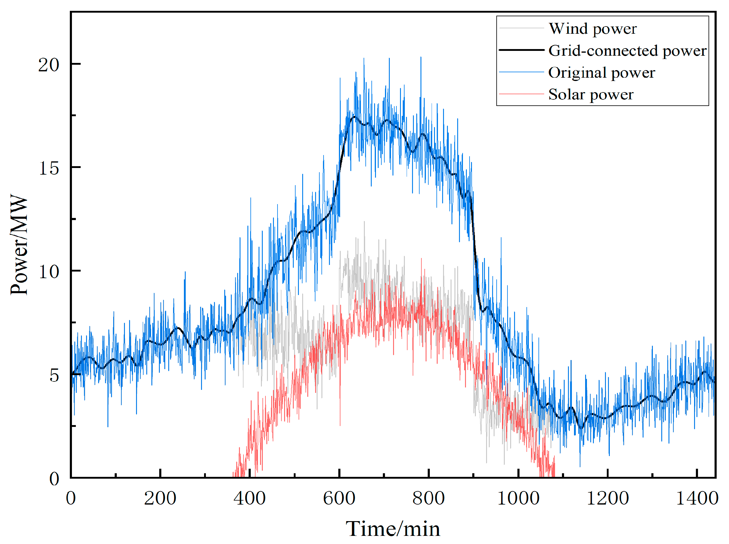
2.2. Fluctuation in Wind–Solar Power Grid Connection

To calculate the power fluctuation rate using 1-min intervals and 10-min intervals in active power fluctuations, the formula is typically given as
R rate = p t _ max p t _ min p r a t
where p r a t is the installed capacity, R rate is the volatility, p t _ max and p t _ min are the maximum and minimum power in the time window, respectively.
The grid fluctuation requirements for wind–solar power plants are shown in Table 1.
From Table 1, it can be seen that the rate of change in power for 1-min intervals cannot exceed 10% and the rate of change in power for 10-min intervals cannot exceed 33.33%.

3. Power Allocation of Flywheel–Battery HESS

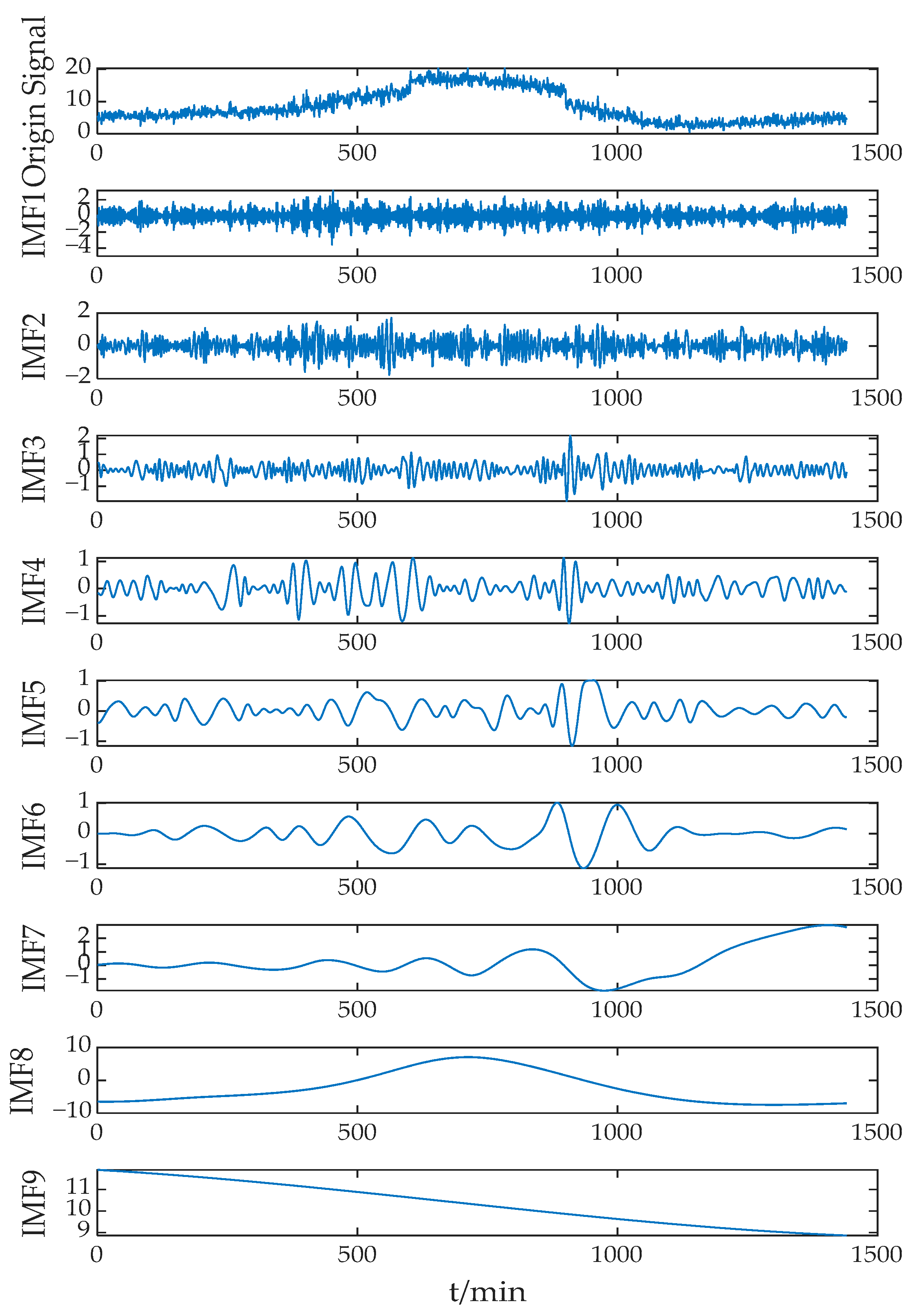
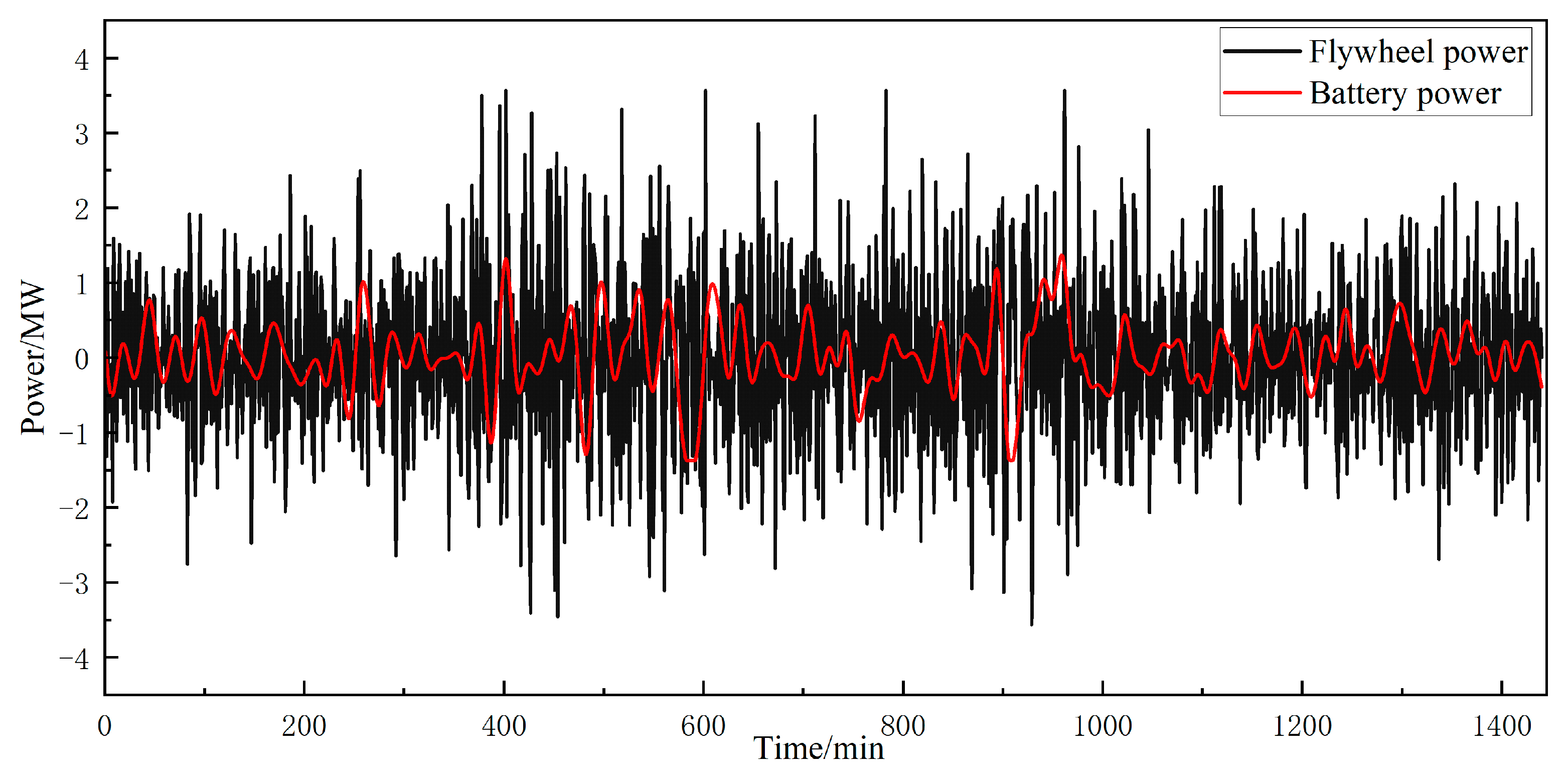
3.1. ICEEMDAN-Based Power Allocation for HESS

ICEEMDAN is a fully adaptive noise-assisted empirical mode decomposition method, which is built on complete ensemble empirical mode decomposition with adaptive noise (CEEMDAN). This algorithm decomposes the input signal into a series of intrinsic mode functions (IMFs) and a residual component. Contrary to CEEMDAN, in order to prevent the excessive introduction of noise, ICEEMDAN does not directly add Gaussian white noise in the decomposition process. Instead, the K-th IMF component of the white noise after empirical mode decomposition (EMD) is selected to conduct the decomposition [31]. The specific steps are as follows:
The decomposed Gaussian white noise IMF component ω i ( i = 1 , 2 , , n ) is added to the original signal s t to obtain the extended signal:
s i t = s t + a 0 ξ i
where a 0 = λ σ ( s ( t ) ) / σ ( ω i ) is the standard deviation of the white noise, λ ∈ [0.02, 0.2] denotes a constant, and σ ( ) represents the sign of the standard deviation operation. This indicates the first IMF component of the signal after EMD.
We calculate the local mean of s i t by EMD and define the first residual margin as r 1 and the first IMF value as IMF 1 :
r 1 = 1 N i = 1 N M s i ( t )
IMF 1 = s ( t ) r 1
where the M operator is invoked and M s i ( t ) is the first component obtained by subtracting the EMD from s i ( t ) .
We calculate the second residual margin r 1 and derive the second IMF value by local mean decomposition:
r 2 = 1 N i = 1 N M r 1 + a 1 ξ 2
IMF 2 = r 1 r 2
where a 1 = λ σ ( r 1 ) .
Recursively, by this method, we calculate the k th residual margin r k and derive the k th IMF value:
r k = 1 N i = 1 N M r k 1 + a k 1 ξ k
IMF k = r k 1 r k
where a k 1 = λ σ r k 1 .
We iterate until the computational decomposition is complete, yielding the full IMF components and residual residuals.
After ICEEMDAN decomposition, a series of IMF components with frequencies ranging from high to low and a residual component are obtained. Then, a suitable IMF order is selected for reconstruction to obtain the high-frequency signal and low-frequency signal, while the high-frequency signal is used as the power signal for hybrid energy storage. In addition, the low-frequency signal is used as the grid-connected power signal to access the grid. In order to meet the Chinese wind–solar grid-connected standard, a suitable crossover frequency point needs to be selected [32].
P hess ( t ) = i = 1 d IMF ( i )
P bw ( t ) = i = d + 1 k IMF ( i )
where P hess ( t ) is the hybrid storage distribution power signal; P bw ( t ) is the grid-connected power signal.

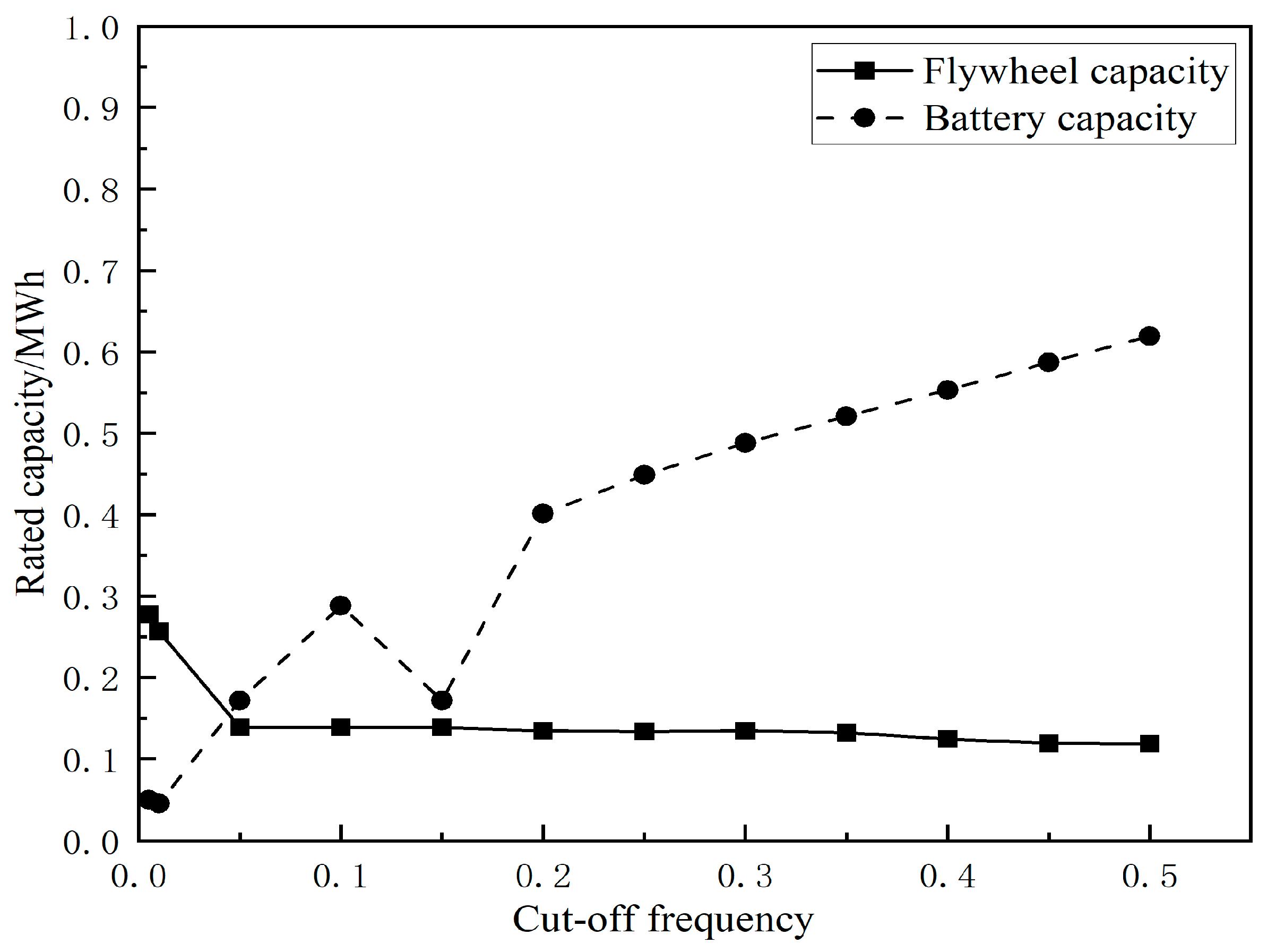
3.2. Secondary Power Allocation Based on Low-Pass Filtering

In order to fully utilize the respective performance of the flywheel–battery, the hybrid energy storage allocation power signal P hess ( t ) is low-pass-filtered to obtain the battery energy storage reference power signal P bess ( t ) and the flywheel energy storage reference power signal P fess ( t ) :
P bess ( t ) = P hess ( t ) / 1 + 1 / ( 2 π f c )
P fess ( t ) = P hess ( t ) P bess ( t )
where f c is the cutoff frequency of the low-pass filter.

4. Mathematical Model for Optimal Allocation of Energy Storage

4.1. Objective Function

The objective of the optimal allocation of hybrid energy storage independently participating in FM is the maximum benefit of energy storage, expressed as
Y = min C HESS
Hybrid energy storage consists of flywheels and batteries, and usually only the investment cost, O&M cost, depletion cost, and replacement cost are considered, without considering the end-of-life disposal cost and the shortage penalty cost [33]. The cost C HESS is calculated as
C HESS = C ESS F + C ESS L
C ESS = C i + C o + C r
The cost of investment C i is
C i = ι = 1 T icc ( s pi P rat + s ei E rat ) ( 1 + r ) ι
where s pi and s ei represent unit power cost and unit capacity cost, respectively; r = 5% denotes the discount rate; T i c c = 20 is the full lifecycle; P rat is rated power; and E rat represents the rated capacity.
O&M cost is defined as
C o = s po P rat 1 + r T icc 1 r 1 + r T icc
where s po denotes the maintenance cost per unit of power.
Replacement cost, C r , is expressed as
C r = m ( E rat s p o p _ e + P rat s p o p _ p )
where m means the number of replacements, s p o p _ e stands for replacement cost per unit of capacity, and s p o p _ p denotes replacement cost per unit of power.

4.2. Constraints

4.2.1. Power Constraints

The charging and discharging power of the energy storage system shall meet the requirements of the leveling power directive, and the rated power is not less than the leveling power directive.
P ι L + P ι F = P hess ( t )
P F max P fess ( t ) β f , P fess ( t ) β f
P L max P bess ( t ) β b , P fess ( t ) β b
where P ι F and P ι L denote the rated power of the flywheel and battery, and β f and β b mean the charging and discharging efficiency of the flywheel and battery. P fess ( t ) > 0 and P bess ( t ) < 0 denote energy storage charging, and P fess ( t ) < 0 and P bess ( t ) < 0 mean energy storage discharging.

4.2.2. SOC Constraints

soc t = soc t 1 + 1 E rat t 1 t ( η P c h a ( t ) P d i s ( t ) η ) d t
s o c min s o c t s o c max
where soc t is energy storage charge state at the time t, P c h a ( t ) is the energy storage charging power, P d i s ( t ) is the energy storage discharging power, and η is the energy storage charging and discharging efficiency.

4.2.3. Capacity Constraint

The capacity of the energy storage system shall meet the leveling demand, and the maximum and minimum values of the change in the capacity of the energy storage equipment per unit of operating time shall be used as the rated capacity reference.
E t = t 1 t P   ( t ) d t
E rat max ( max E t min E t s o c max s o c min )
where E t denotes the cumulative capacity during the sampling period.

4.2.4. Considering the Economic Constraints of the Full Lifecycle of the Battery
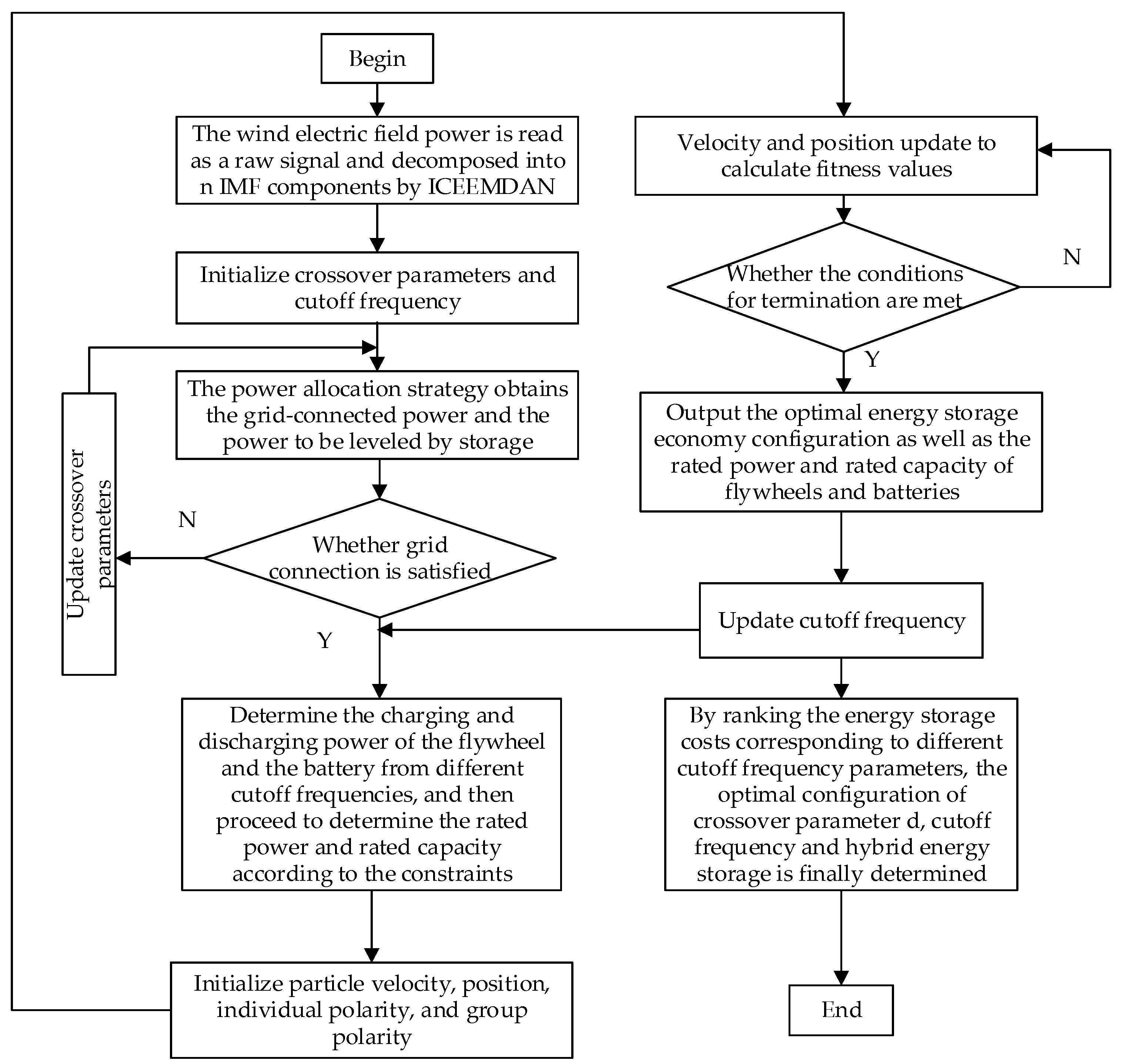
In the flywheel–battery HESS, the use cycle of flywheel energy storage system is generally 20 years and it does not need to be replaced. However, the service life of the battery is limited by its own charging and discharging depth, which cannot be operated normally during long-term operation. Therefore, the replacement frequency of battery energy storage systems in practical engineering needs to be considered. The number of cycles at different discharge depths is obtained using the rainflow counting method, by fitting the correspondence between the discharge depth and the maximum number of cycles into a functional relationship [34]. According to the literature, the relationship between the fitted energy storage battery discharge depth and the maximum number of cycles is
N max ( D OD i ) = 1653.012 / D OD i + 3123.2932
N i = N max ( 1 ) N max ( D OD i )
where D OD i is the depth of discharge for the first storage, N max denotes the maximum number of cycles at this depth of discharge, N i means the equivalent number of cycles at full discharge for one discharge, and N max ( 1 ) means the maximum number of cycles corresponding to full discharge.
The number of full lifecycle battery replacements is
m = 365 × a × i = 1 k N i N max ( 1 )
where a is service life, and k means the sampling cycle length in min.

5. Improved PSO

The asymmetric acceleration factor is used to improve the optimization, increasing the spatial search and reducing the influence of local extremes. Therefore, a larger acceleration factor is selected in the initial search, and a smaller acceleration factor strengthens the scope of the particle search. When performing iterative calculations, the linearly decreasing and linearly increasing factors enhance the particle’s global optimal convergence ability. The formula is given as
C 1 = C 1 s + k ( C 1 e C 1 s ) / k max
C 2 = C 2 s + k ( C 2 e C 2 s ) / k max
where C 1 s and C 2 s are the final values of the acceleration factor, C 1 e and C 2 e are the initial values of the acceleration factor, and k and k max are the number of iterations and maximum number of iterations, respectively.
The improved particle swarm algorithm solution process is
v i , d k + 1 = ω v i , d k + c 1 r 1 ( p i , d k x i , d k ) + c 2 r 2 ( p d k x i , d k )
x i , d k + 1 = x i , d k + v i , d k + 1
where ω stands for the weight coefficient; r 1 , r 2 ∈ [0, 1] are random constants; and v i , d k and x i , d k denote the speed and position of the first iteration, respectively.
The PSO algorithm is used to solve the hybrid energy storage capacity allocation economics model and the flowchart is shown in Figure 2.
The specific steps are as follows:
  • Read the power of the wind–solar generating station as the original signal, obtaining the grid-connected signal and the suppression command signal by the ICEEMDAN decomposition method and initializing the crossover parameter and the cutoff frequency.
  • According to the power distribution strategy, the grid-connected signal and the energy storage to be stabilized signal are obtained to determine whether the grid-connected signal meets the conditions. If not, update the crossover frequency parameters; if the conditions are met, determine the charging and discharging power of the flywheel and the battery based on the cutoff frequency, and then determine the initial power and capacity.
  • Initialize the particle velocity, position, individual polarity, and group polarity by taking the initial power and capacity of the flywheel and battery as the minimum value of the rated power and rated capacity.
  • Update the particle velocity, position, individual extreme value, and group extreme value, and process the boundary constraints.
  • Interpret whether the termination conditions are met and determine the optimal energy storage economy configuration as well as the rated power and rated capacity of the flywheel and battery.

6. Calculation Example Analysis

This paper establishes a wind-solar-energy storage microgrid model using MATLAB/Simulink R2022b. Actual data from a 10 MW wind plant and a 10 MW solar plant in a local microgrid were utilized as the raw power signals for wind–solar power, sampled at 1-min intervals. An HESS combining flywheel and battery technologies was employed to mitigate wind–solar power generating fluctuations. Relevant parameters are shown in Table 2.
Figure 3 presents the curves for the original wind–solar power, initial grid-connected power, and grid-connected power after smoothing. The figure illustrates the random fluctuations of wind–solar power throughout the day, with solar power peaking during daylight hours, particularly around noon, which is in line with the typical daily solar patterns. The smoothed grid-connected power displays significantly reduced fluctuations compared to the original power, indicating the effective stabilization of the output.
The ICEEMDAN method, as described in the previous section, was applied to decompose the raw wind–solar power signals. Figure 4 displays the decomposed intrinsic mode function (IMF) components. From the diagram, it can be seen that the original signal is decomposed into multiple modal components. From IMF1 to IMF9, the high-frequency components decrease and the low-frequency components increase. In order to meet the wind–solar grid-connected standard, the frequency division parameter was selected to be 5, and the grid-connected power and the stabilized command power were determined.
For the wind–solar power output data shown in Figure 3, the power fluctuation rate was calculated using Equation (1), with 1-min intervals and 10-min interval time windows. The results are presented in Figure 5 and Figure 6. Before smoothing, the maximum power fluctuation rates in 1-min intervals were 51% for wind power and 58% for solar power, while the maximum power fluctuation rates in 10-min intervals were 61% for wind power and 49% for solar power. As shown in Figure 5, after applying the flywheel–battery HESS, the maximum power fluctuation rate in 1-min intervals was reduced to 3.2%. For the 10-min intervals, as illustrated in Figure 6, the majority of the power fluctuation rates remained below 8% in most cases, with a signal peak of 30.25% occurring around the 900-min mark. This anomaly was caused by a sharp decrease in wind power output between 880 and 910 min, alongside a gradual decline in solar output due to reduced sunlight intensity. These factors led to significant fluctuations in the original power levels, resulting in a peak in the grid-connected power fluctuation rate after smoothing. However, for the 1-min intervals, the original power output exhibited a smooth decline without severe fluctuations, and the smoothed grid-connected power met the allowable fluctuation standards.
The PSO algorithm was applied to determine the optimal hybrid energy storage capacity configuration under different cutoff frequencies. Figure 7 shows the power distribution of the HESS. As shown in Figure 7, with the increase in cutoff frequency, the allocation of high-frequency signals to the flywheel decreased, leading to a declining trend in the required flywheel power capacity. Conversely, the allocation of low-frequency signals to the battery increased, resulting in a rising trend in the required battery power capacity.
At lower cutoff frequencies, the flywheel was responsible for a larger proportion of high-frequency components, which increases system costs. Conversely, at higher cutoff frequencies, the battery absorbed more high-frequency components, leading to more frequent charge–discharge cycles, greater fluctuations in the state of charge (SOC), and deeper discharge levels. This accelerates battery degradation, raises replacement frequency, and impacts the overall system cost and performance.
The hybrid energy storage capacity configuration is shown in Figure 8. When the cutoff frequency was low, a higher proportion of power instructions was allocated to the flywheel storage, resulting in an increase in its required capacity. The battery storage responded to low-frequency power instructions, requiring less capacity. However, as the cutoff frequency increased, the high-frequency instructions decreased while low-frequency instructions increased. As a result, the required capacity for the flywheel storage decreased, while the required capacity for the battery storage increased.
Figure 9 illustrates the relationship between hybrid energy storage costs and various cutoff frequencies, which showed a decreasing trend when the cutoff frequency was below 0.1 and an increasing trend when it exceeded 0.1. Consequently, the optimal hybrid energy storage configuration was achieved at a cutoff frequency of 0.1.
As shown in Table 3, hybrid energy storage offers substantial cost savings compared to single-battery energy storage. In the hybrid system, flywheel energy storage handles high-frequency leveling commands, while battery storage addresses only low-frequency commands. This division reduces both the number of battery charge–discharge cycles and the depth of discharge, which results in a lifecycle where the battery requires only one replacement. In contrast, a single-battery storage system experiences frequent charge–discharge cycles, which necessitates more frequent replacements and consequently higher costs. Additionally, with the integration of opportunity compensation cost, the rated power requirement for hybrid energy storage is lowered, as higher-leveling commands are partially managed by other fast-response systems, further decreasing total system costs.
The SOC deviation before and after long-term charge–discharge cycles, Δ S O C , the average output power of energy storage, P a v e , and the root mean square (RMS) value of the SOC, Δ S O C r m s are defined as evaluation indicators [35,36]. The analysis of these evaluation indicators for the HESS configuration is shown in Table 4.
Δ S O C = S O C end S O C start
P a v e = 1 N i = 1 N p i
Δ S O C r m s = 1 N i = 1 N S O C i S O C s t a r t
From Table 4, it can be observed that the average output power of the flywheel energy storage is 2.73 times that of the battery energy storage, aligning with the strategy where the flywheel responds to high-frequency outputs while the battery handles low-frequency outputs. Additionally, the SOC deviation of the battery at the end of the simulation is smaller compared to the flywheel. The root mean square (RMS) value of the flywheel’s SOC is 5.37 times that of the battery’s SOC, indicating that the SOC fluctuations in the flywheel are more pronounced due to its response to high-frequency signals. In contrast, the battery’s SOC exhibits smaller variations because it primarily responds to low-frequency outputs.
In the optimal configuration, Figure 10 shows the changes in the SOC for both flywheel and battery storage. The SOC of the flywheel reacts quickly to high-frequency leveling commands, while the SOC of the battery varies more gradually, exhibiting a lower depth of discharge due to its primary response to low-frequency leveling commands and discharge depth constraints. Figure 11 illustrates the comparison of power output from the flywheel and battery. The flywheel energy storage system handles the majority of high-frequency commands, resulting in frequent changes in output power. Battery energy storage manages the low-frequency signal with gentle fluctuations on the time scale, and the output power changes more slowly. The combined effect improves system economy while effectively suppressing wind–solar fluctuations.

7. Discussion

The Guiding Opinions on Accelerating the Development of New Types of Energy Storage emphasize that shared energy storage, as an innovative mechanism, can optimize the market-based allocation of storage resources and enhance the system’s low-carbon benefits. By integrating and coordinating distributed storage resources, energy sharing not only improves the system’s capacity to consume renewable energy but also plays an active role in carbon reduction, providing strong support for achieving low-carbon targets. Effectively integrating and utilizing decentralized energy resources is one of the key research directions for the future. Reference [37] introduces the concept of “cloud energy storage”, aiming to establish an interactive sharing mechanism between prosumers and the power grid. Reference [38] explores the integration of distributed energy storage in residential and commercial sectors and develops a cloud energy storage operation model to facilitate the sharing of diverse energy resources. Reference [39] investigates the coordinated management of electricity, heat, and natural gas resources within integrated energy systems, constructing a flexible and efficient multi-energy sharing platform that enhances the interaction between different energy storage systems and integrated energy systems.
For the hybrid energy storage studied in this paper, one of the key research directions is how to coordinate its management with other renewable energy sources through a virtual platform. Balancing the returns for energy storage investors while meeting the requirements of service providers presents a significant challenge. Integrating hybrid energy storage into an integrated energy system requires careful consideration of policies, economic markets, and various supporting factors to ensure feasibility and efficiency.

8. Conclusions

This study proposes a flywheel–battery HESS to smooth wind–solar power generating fluctuation. By optimizing the power and capacity configuration of the flywheel and battery, the fluctuation in wind–solar power generation output can be smoothed in a low-cost and high efficiency manner. The main research contents are as follows.
(1)
The ICEEMDAN method is employed to decompose the original wind–solar power signal into a grid-connected power signal and a leveling command signal. A low-pass filter is then applied to separate the leveling command signal by frequency, allocating the appropriate components to the flywheel and battery within the HESS.
(2)
To optimize capacity allocation, a hybrid flywheel–battery storage model is established, considering the impact of different cutoff frequencies on power allocation, as well as the effects of the depth of discharge and cycle count on battery lifespan over its entire lifecycle. The PSO (particle swarm optimization) algorithm is employed to solve this model and determine the optimal energy storage capacity configuration.
(3)
A simulation analysis was conducted on a microgrid consisting of 10 MW wind power generation, 10 MW solar power generation, and the flywheel–battery HESS. The results showed that the use of hybrid energy storage had a significant power smoothing effect, with a maximum power fluctuation rate of 3.2% within 1-min intervals. The maximum power fluctuation within 1-min intervals was mostly below 8%. Under the same stabilizing effect, the HESS achieved a 45.1% reduction in costs compared to single-battery energy storage. This demonstrated the wind–solar power leveling capability and economic value of the flywheel–battery HESS.
This research currently has certain limitations, such as only utilizing one day’s actual output data, considering only the cost impact of energy storage, and not analyzing in conjunction with aspects like the electricity market and energy storage policies.
In the future, the initial investment cost of flywheel–battery hybrid energy storage is expected to decrease further due to the influence of various policies and the continued expansion of wind–solar power plants. As the demand for hybrid energy storage increases, market-driven cost reductions may also occur. Once deployed, hybrid energy storage systems can generate revenue by participating in local electricity markets, frequency regulation, and peak shaving.
In recent years, the concept of community energy storage has emerged, expanding the application scenarios of storage technologies and increasing their potential benefits. For instance, in vehicle-to-grid (V2G) applications, energy storage systems are required to operate either temporarily or for extended periods.
Therefore, in the next phase of our research, we will focus on flywheel–battery hybrid energy storage as the foundation and select specific community areas coupled with wind-PV power stations as application scenarios. Within these regions, we will consider the impact of “dual-carbon” policies on initial hybrid storage investment costs, post-deployment subsidies, participation in local electricity market transactions, frequency regulation, and community shared storage benefits. The objective will be to optimize hybrid energy storage capacity allocation to maximize economic returns.

Author Contributions

Conceptualization, S.W. and Y.G.; methodology, S.W. and Y.G.; software, Y.G. and X.M.; formal analysis, Y.G. and S.Z.; investigation, Y.G. and S.Z.; writing—original draft preparation, Y.G. and S.W.; writing—review and editing, S.W., C.W. and X.M.; project administration, S.W.; funding acquisition, S.W. All authors have read and agreed to the published version of the manuscript.

Funding

This research was funded by Jiangsu Collaborative Innovation Center for Smart Distribution Network project (XTCX202412) and Jiangsu Major Science and Technology project (BG2024011).

Data Availability Statement

The original contributions presented in the study are included in the article. Further inquiries can be directed to the corresponding author.

Conflicts of Interest

The authors declare no conflicts of interest.

References

  1. Yang, P.; Liu, F.; Jiang, Q.R.; Mao, H.Y. Stability of large disturbances in “double-high” power systems: Problems, challenges and prospects. J. Tsinghua Univ. (Sci. Technol.) 2021, 61, 403–414. [Google Scholar]
  2. Sayed, E.T.; Olabi, A.G.; Alami, A.H.; Radwan, A.; Mdallal, A.; Rezk, A.; Abdelkareem, M.A. Renewable Energy and Energy Storage Systems. Energies 2023, 16, 1415. [Google Scholar] [CrossRef]
  3. Notton, G.; Nivet, M.-L.; Voyant, C.; Paoli, C.; Darras, C.; Motte, F.; Fouilloy, A. Intermittent and stochastic character of renewable energy sources: Consequences, cost of intermittence and benefit of forecasting. Renew. Sustain. Energy Rev. 2018, 87, 96–105. [Google Scholar] [CrossRef]
  4. Rajah, I.; Sowe, J.; Schimpe, M.; Barreras, J.V. Degradation-Aware Derating of Lithium-Ion Battery Energy Storage Systems in the UK Power Market. Electronics 2024, 13, 3817. [Google Scholar] [CrossRef]
  5. Chang, H.; Xing, Y.; Miao, B.; Li, L.; Liu, C.; Xiang, K.; Chi, Y.; Liu, Y. A Quantitative Method of Carbon Emission Reduction for Electrochemical Energy Storage Based on the Clean Development Mechanism. Processes 2024, 12, 2472. [Google Scholar] [CrossRef]
  6. Kouba, N.E.Y.; Sadoudi, S. Optimal Power Management and Control of Hybrid Solar–Wind Microgrid Including Storage System. Proceedings 2024, 105, 3. [Google Scholar] [CrossRef]
  7. Ministry of Finance of China. New Guidelines for the Management of Special Funds for Clean Energy Development. Available online: https://www.china5e.com/rule/news-878267-1.html (accessed on 22 March 2025).
  8. Dongyang Municipal Government. Local Energy Storage Subsidy Policy. Available online: https://www.china5e.com/news/news-1184001-1.html (accessed on 22 March 2025).
  9. Australian Renewable Energy Agency (ARENA). Funding Support for Battery Storage Projects. Available online: https://www.china5e.com/news/news-1184001-1.html (accessed on 22 March 2025).
  10. Politico. World’s Largest Battery Plant on Fire in Central California. Politico. 2025. Available online: https://www.politico.com/news/2025/01/17/worlds-largest-battery-plant-on-fire-in-central-california-00198914 (accessed on 23 March 2025).
  11. Hang, X.; Ruan, P.; Zhang, L.; Li, J.; Tian, G.; Hu, D.; Zhu, B. Application analysis of flywheel energy storage in thermal power frequency modulation in central China. Energy Storage Sci. Technol. 2021, 10, 1694–1700. [Google Scholar]
  12. Mousavig, S.M.; Faraji, F.; Majazi, A.; Al-Haddad, K. A comprehensive review of flywheel energy storage system technology. Renew. Sustain. Energy Rev. 2017, 67, 477–490. [Google Scholar] [CrossRef]
  13. Sharma, P.; Kumar, V. Current technology of supercapacitors: A review. J. Electron. Mater. 2020, 49, 3520–3532. [Google Scholar] [CrossRef]
  14. Hong, F.; Liang, L.; Pang, Y.L.; Jia, X.Y.; Fang, F. Adaptive cooperative sag-based primary FM control strategy for flywheel energy storage combined thermal power units. Therm. Power Gener. 2023, 52, 36–44. [Google Scholar]
  15. Leclanche; S4 Energy. Flywheel-Lithium Battery Hybrid Energy Storage System in The Netherlands. Polaris Power News Network. Available online: https://www.china5e.com/news/news-1099175-1.html (accessed on 22 March 2025).
  16. State Grid Shanxi Electric Power Research Institute. Hybrid Energy Storage Frequency Regulation Experiment in Youyu Laoqianshan Wind Farm. Polaris Power News Network. Available online: https://www.china5e.com/news/news-1184001-1.html (accessed on 23 March 2025).
  17. Yan, Q.M.; Liu, Y.C.; Dong, X.Z.; Ma, Y.X. Optimal allocation of hybrid energy storage capacity based on CEEMDAN-HT for smoothing PV output. Power Syst. Prot. Control 2022, 50, 43–53. [Google Scholar]
  18. Teng, W.; Xu, Q.X.; Wang, Y.J.; Qin, R.; Wu, X.; Liu, Y.B. Economic configuration of flywheel cooperative battery hybrid energy storage system for smoothing wind power fluctuation. J. Chin. Soc. Power Eng. 2024, 44, 1101–1108. [Google Scholar]
  19. Wang, J.J.; Gou, K.J.; Chen, H.; Chen, H.G.; Xue, G.; Zhang, G.Q. Optimal allocation of flywheel-electrochemical hybrid energy storage capacity for smoothing wind power fluctuation. J. Chin. Soc. Power Eng. 2024, 44, 439–446. [Google Scholar]
  20. Hao, X.W. Application Study of Hybrid Energy Storage for Smoothing Wind Power Output Fluctuation; North China Electric Power University: Beijing, China, 2023. [Google Scholar]
  21. Wang, S. Research on Hybrid Energy Storage Capacity Allocation Method for Photovoltaic Power Levelling; North China Electric Power University: Beijing, China, 2023. [Google Scholar]
  22. Lu, Q.Y.; Yang, Y.G.; Chen, J.S.; Liu, Y.; Liu, N.; Cao, F. Capacity optimization of hybrid energy storage systems for offshore wind power volatility smoothing. Energy Rep. 2023, 9, 575–583. [Google Scholar] [CrossRef]
  23. Li, H.Z.; Sun, D.Y.; Li, B.K.; Wang, X.; Zhao, Y.; Wei, M.; Dang, X. Collaborative optimization of VRB-PS hybrid energy storage system for large-scale wind power grid integration. Energy 2023, 265, 126292. [Google Scholar] [CrossRef]
  24. Zhang, Y.; Xu, Y.J.; Guo, H.; Zhang, X.; Guo, C.; Chen, H. A hybrid energy storage system with optimized operating strategy for mitigating wind power fluctuations. Renew. Energy 2018, 125, 121–132. [Google Scholar] [CrossRef]
  25. He, B.; Ren, Y.F.; Jia, W.Q.; Xue, Y.; Yang, P.W.; Ren, Z. Study on the strategy of energy storage MPC for smoothing the power fluctuation of decentralized wind power. Acta Energiae Solaris Sin. 2024, 45, 132–139. [Google Scholar]
  26. Sun, Z.L.; Chen, J.; Yan, Y.L.; Zhang, B.M.; Wang, Z.D.; Jiao, D.D. Coordinated control of dual-stack self-cycling based on hybrid energy storage for smoothing wind power fluctuations. Acta Energiae Solaris Sin. 2021, 42, 125–132. [Google Scholar]
  27. Zhang, Y.; Wu, Y.; Li, L.; Liu, Z. A Hybrid Energy Storage System Strategy for Smoothing Photovoltaic Power Fluctuation Based on Improved HHO-VMD. Int. J. Photoenergy 2023, 2023, 9633843. [Google Scholar] [CrossRef]
  28. Mehrdad, G.; Omkolsoom, S.; Navid, R.; Hassan, B. Optimum storage sizing in a hybrid wind-battery energy system considering power fluctuation characteristics. J. Energy Storage 2022, 52, 104634. [Google Scholar]
  29. Villa-Ávila, E.; Arévalo, P.; Ochoa-Correa, D.; Iñiguez-Morán, V.; Jurado, F. A New Adaptive Strategy for Enhancing the Stability of Isolated Grids through the Integration of Renewable Energy and V2G Management. Appl. Sci. 2024, 14, 6380. [Google Scholar] [CrossRef]
  30. Tang, X.S.; Sun, Y.S.; Zhou, G.P.; Miao, F.F. Coordinated control of multi-type energy storage for wind power fluctuation suppression. Energies 2017, 10, 1212. [Google Scholar] [CrossRef]
  31. Li, C.; Qin, L.J. Capacity optimization of hybrid energy storage with independent frequency regulation based on improved particle swarm algorithm. Acta Energiae Solaris Sin. 2023, 44, 426–434. [Google Scholar]
  32. Li, X.; Wan, G.J.; Qiu, Y.; Hou, Y.C.; Zhou, Q. Optimal allocation of hybrid energy storage capacity based on VMD. Acta Energiae Solaris Sin. 2022, 43, 88–96. [Google Scholar]
  33. Song, J.; Geng, L.X.; San, Y.F.; Wen, Y.B.; Sun, P.; Gong, L.J. Hybrid energy storage assisted thermal power unit primary FM capacity planning based on EMD decomposition. Energy Storage Sci. Technol. 2023, 12, 496–503. [Google Scholar]
  34. Xu, Q.X.; Teng, W.; Wu, X.; Liu, Y.B.; Liang, S.Y. Capacity allocation method of flywheel energy storage system for smoothing wind power fluctuation. Energy Storage Sci. Technol. 2022, 11, 3906–3914. [Google Scholar]
  35. Hong, F.; Liang, B.Y.; Sun, F.D.; Liang, L.; Wang, W.; Fang, F. Frequency regulation control strategy of flywheel energy storage coupled with thermal power units in multiple operation stages. Power Gener. Technol. 2024; in press. Available online: http://kns.cnki.net/kcms/detail/33.1405.tk.20241111.1419.002.html (accessed on 22 March 2025).
  36. Wang, J.Y.; Yang, K.; Song, Z.X.; Wu, C.Y.; Bai, Y.L. Primary frequency regulation control strategy for battery-flywheel hybrid energy storage based on adaptive SOC. Power Eng. Technol. 2024, 43, 122–130. [Google Scholar]
  37. Syed, M.M.; Hansen, P.; Morrison, G.M. Performance of a shared solar and battery storage system in an Australian apartment building. Energy Build. 2020, 225, 110321. [Google Scholar] [CrossRef]
  38. Liu, J.; Zhang, N.; Kang, C.; Kirschen, D.; Xia, Q. Cloud energy storage for residential and small commercial consumers: A business case study. Appl. Energy 2017, 188, 226–236. [Google Scholar] [CrossRef]
  39. Sun, L.; Qiu, J.; Han, X.; Yin, X.; Dong, Z.Y. Capacity and energy sharing platform with hybrid energy storage system: An example of hospitality industry. Appl. Energy 2020, 280, 115897. [Google Scholar] [CrossRef]
Figure 1. Topology of wind–solar power and flywheel–battery HESS.
Energies 18 02055 g001
Figure 2. Flowchart of particle swarm algorithm for smoothing wind–solar power.
Energies 18 02055 g002
Figure 3. Wind power and grid-connected power.
Energies 18 02055 g003
Figure 4. IMF components.
Energies 18 02055 g004
Figure 5. One-minute volatility before and after flattening.
Energies 18 02055 g005
Figure 6. Ten-minute volatility before and after flattening.
Energies 18 02055 g006
Figure 7. Power–cutoff frequency relationship.
Energies 18 02055 g007
Figure 8. Capacity-cutoff frequency relationship.
Energies 18 02055 g008
Figure 9. Plot of energy storage cost–cutoff frequency relationship.
Energies 18 02055 g009
Figure 10. SOC state change in the flywheel–battery HESS.
Energies 18 02055 g010
Figure 11. Comparison of flywheel–battery HESS outputs.
Energies 18 02055 g011
Table 1. Grid connection standards [22].
Installed Wind and Solar Power Capacity (MW)Maximum Variation in Active Power (MW)
<30310
30–150installed capacity/10installed capacity/3
>1501550
Table 2. Flywheel–battery full-lifecycle economic parameters [18].
ParametersBatteryFlywheel
Energy storage charge/discharge efficiency/%9095
SOC upper and lower limits(0.2, 0.8)(0.1, 0.9)
SOC initial value0.50.5
Unit power cost of energy storage investment/ ( 1 0 4   CNY · MW 1 ) 200300
Unit capacity cost of energy storage investment/ ( 1 0 4   CNY · MW 1 · h 1 ) 1503000
Energy storage O&M unit power cost/ ( 1 0 4   CNY · MW 1 ) 4020
Energy storage unit replacement power cost/ ( 1 0 4   CNY · MW 1 · h 1 ) 100
Energy storage unit replacement capacity cost/ ( 1 0 4   CNY · MW 1 · h 1 ) 75
Table 3. Comparison of single-battery energy storage and hybrid energy storage economics before and after optimization.
Type of Energy StorageRated Power/MWRated Capacity/MWhReplacement TimesY/
104 CNY
Single-battery energy storageBattery storage4.67940.184364169.87
Hybrid energy storageFlywheel energy storage3.92050.1388-2388.52
Battery storage1.64230.2881
Table 4. Energy storage evaluation indicators.
Energy Storage Type P a v e / M W Δ S O C Δ S O C r m s
Flywheel Energy Storage0.90670.135310.0820
Battery Energy Storage0.33100.006350.0150
Disclaimer/Publisher’s Note: The statements, opinions and data contained in all publications are solely those of the individual author(s) and contributor(s) and not of MDPI and/or the editor(s). MDPI and/or the editor(s) disclaim responsibility for any injury to people or property resulting from any ideas, methods, instructions or products referred to in the content.

