
Insight into the Impact of Blade Perforation on the Aerodynamics and Acoustics of a Two-Stage Variable-Pitch Axial Fan

Abstract
1. Introduction
2. Methodology
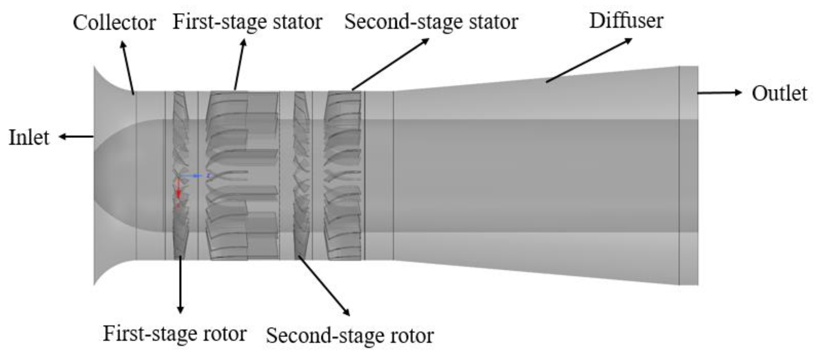
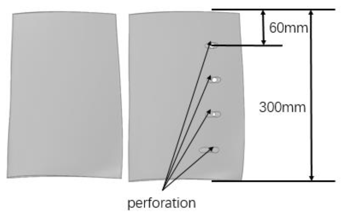
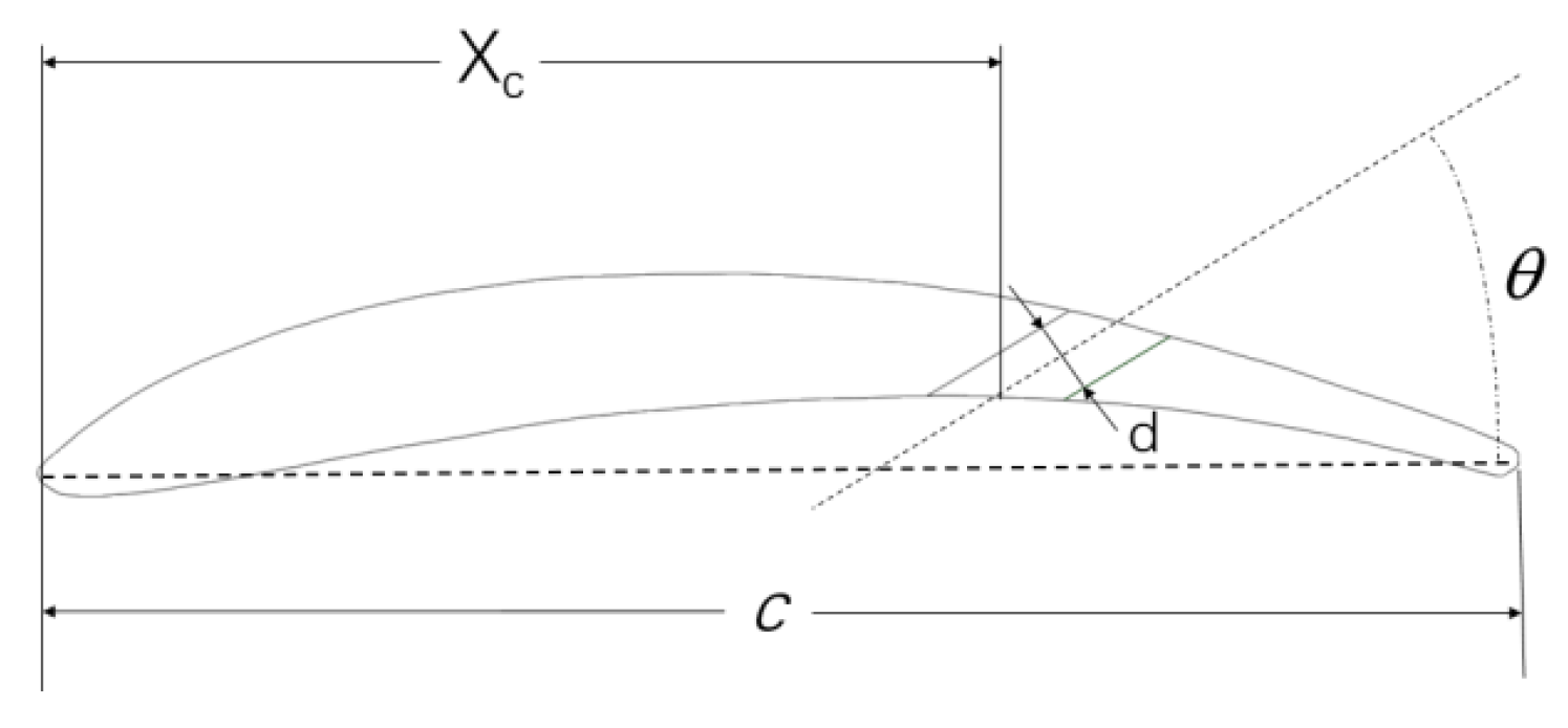
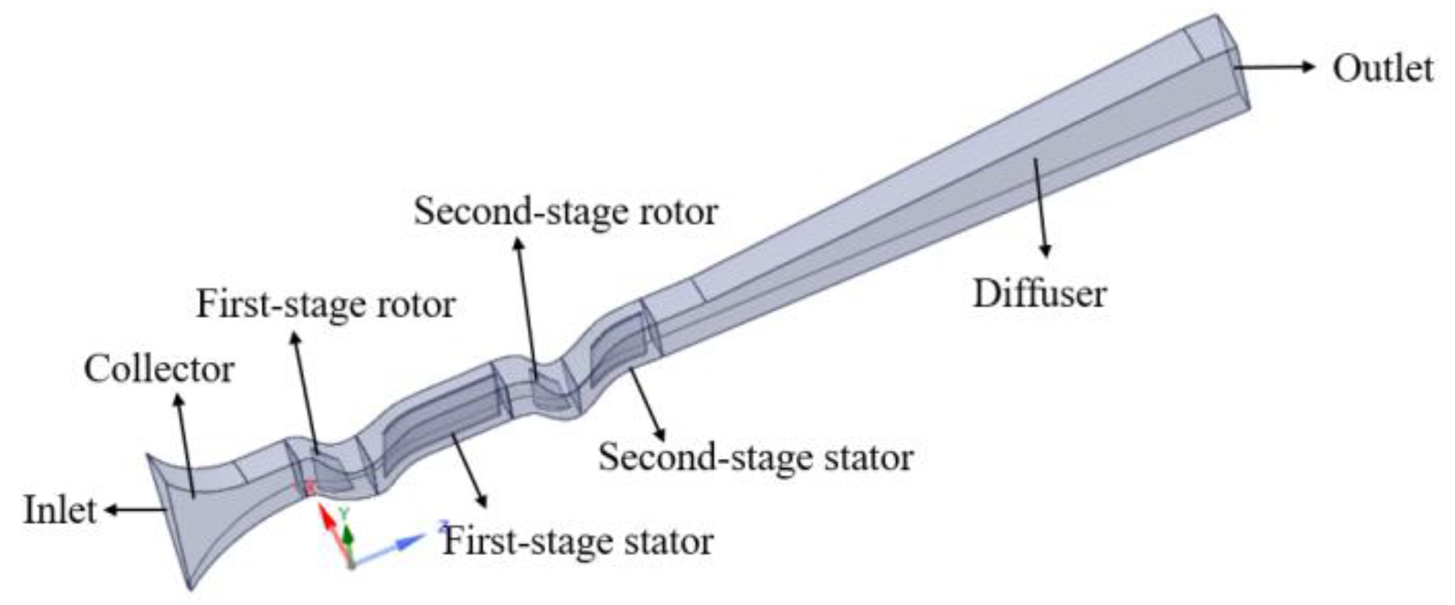
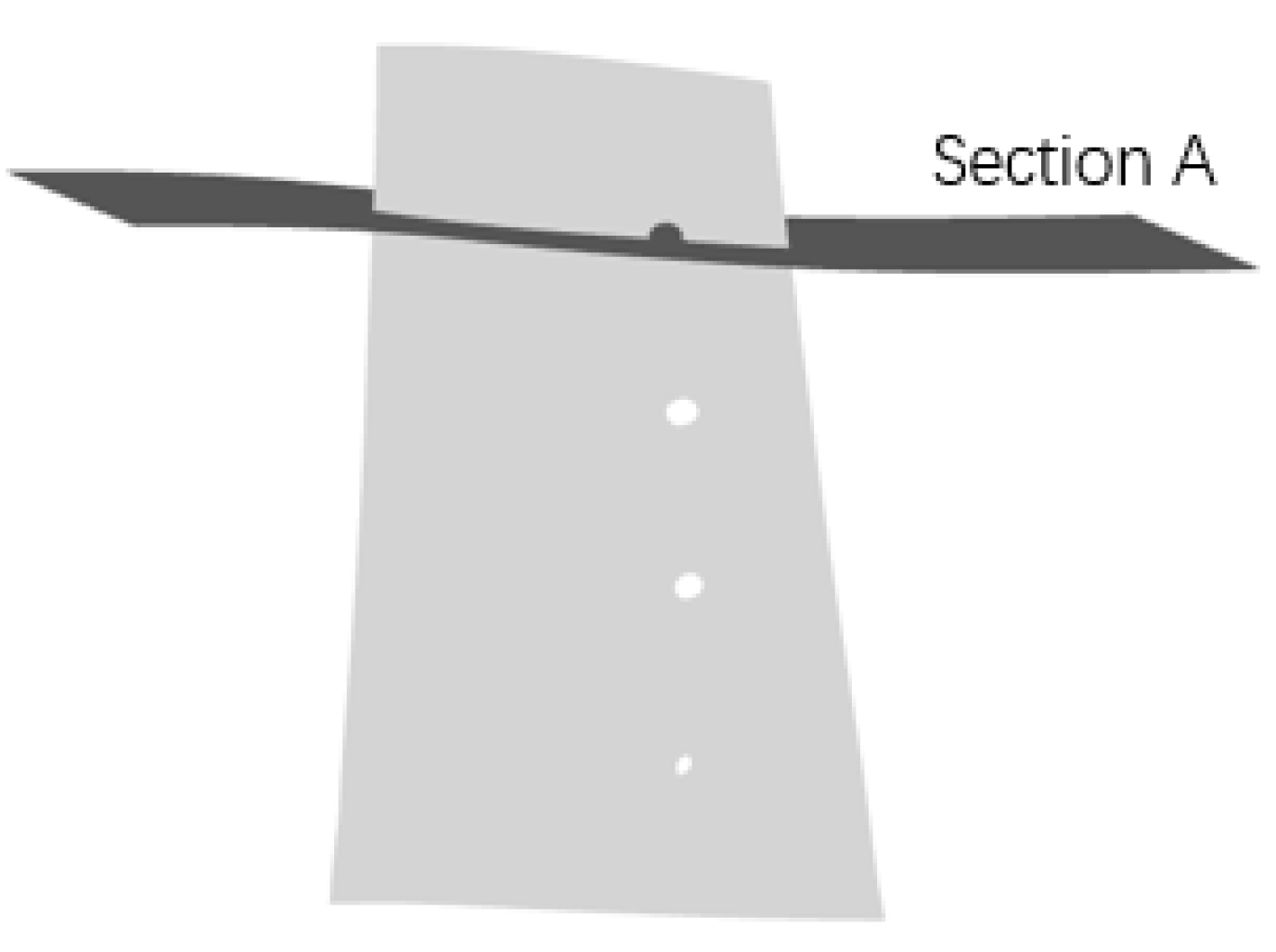
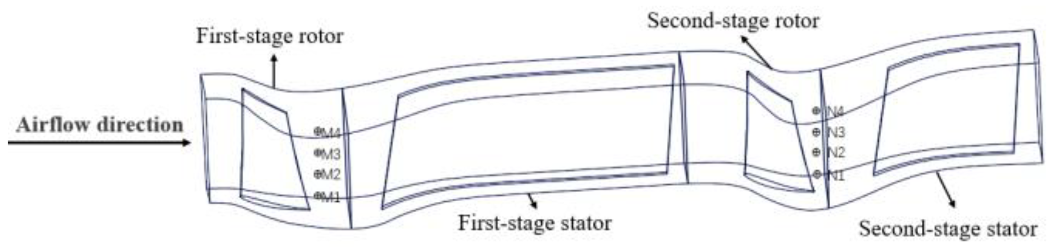
2.1. Fan Model
2.2. Numerical Method and Boundary Conditions
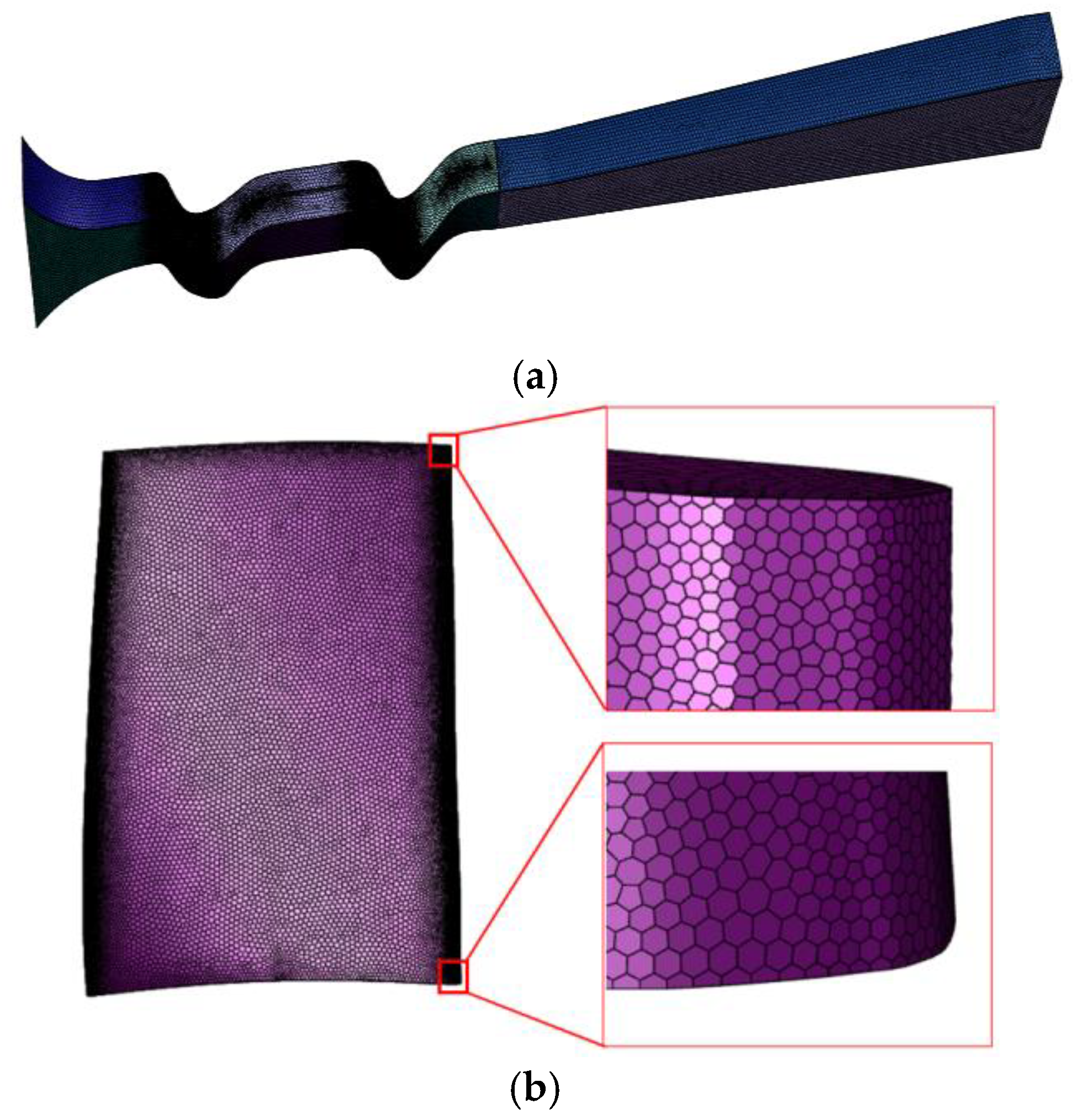
2.3. Verification of Grid Independence
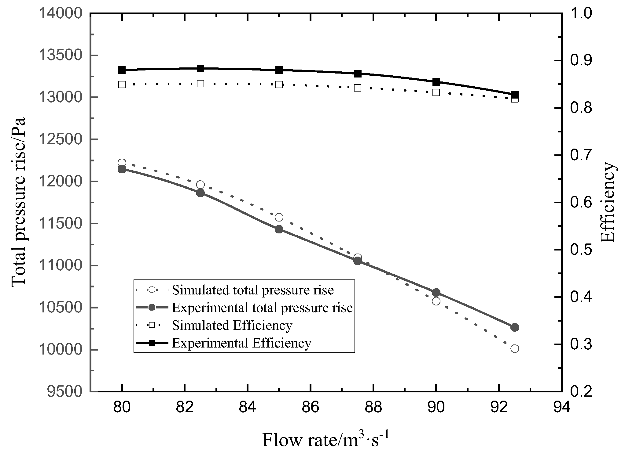
2.4. Validation of Numerical Simulation
3. Results and Discussion
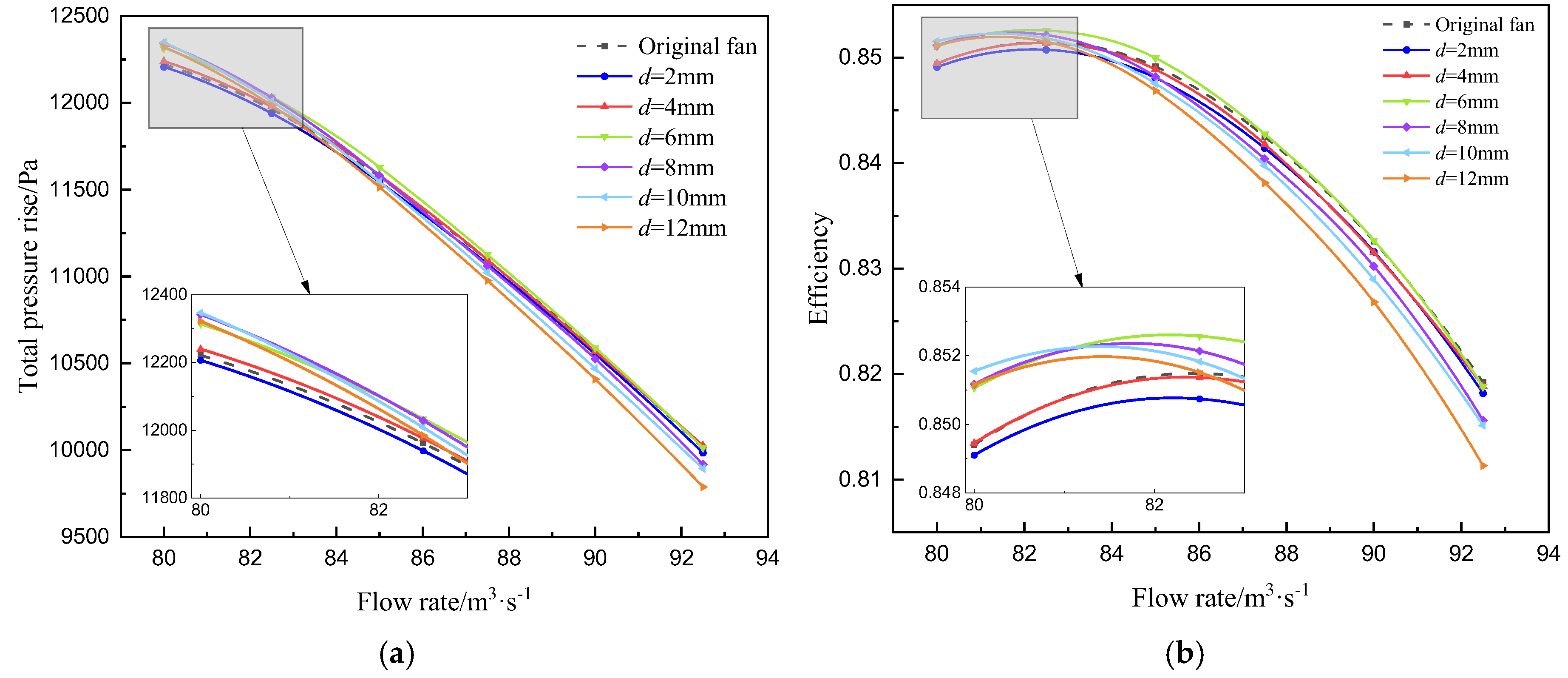
3.1. Aerodynamic Performance
3.2. Internal Flow Characteristics
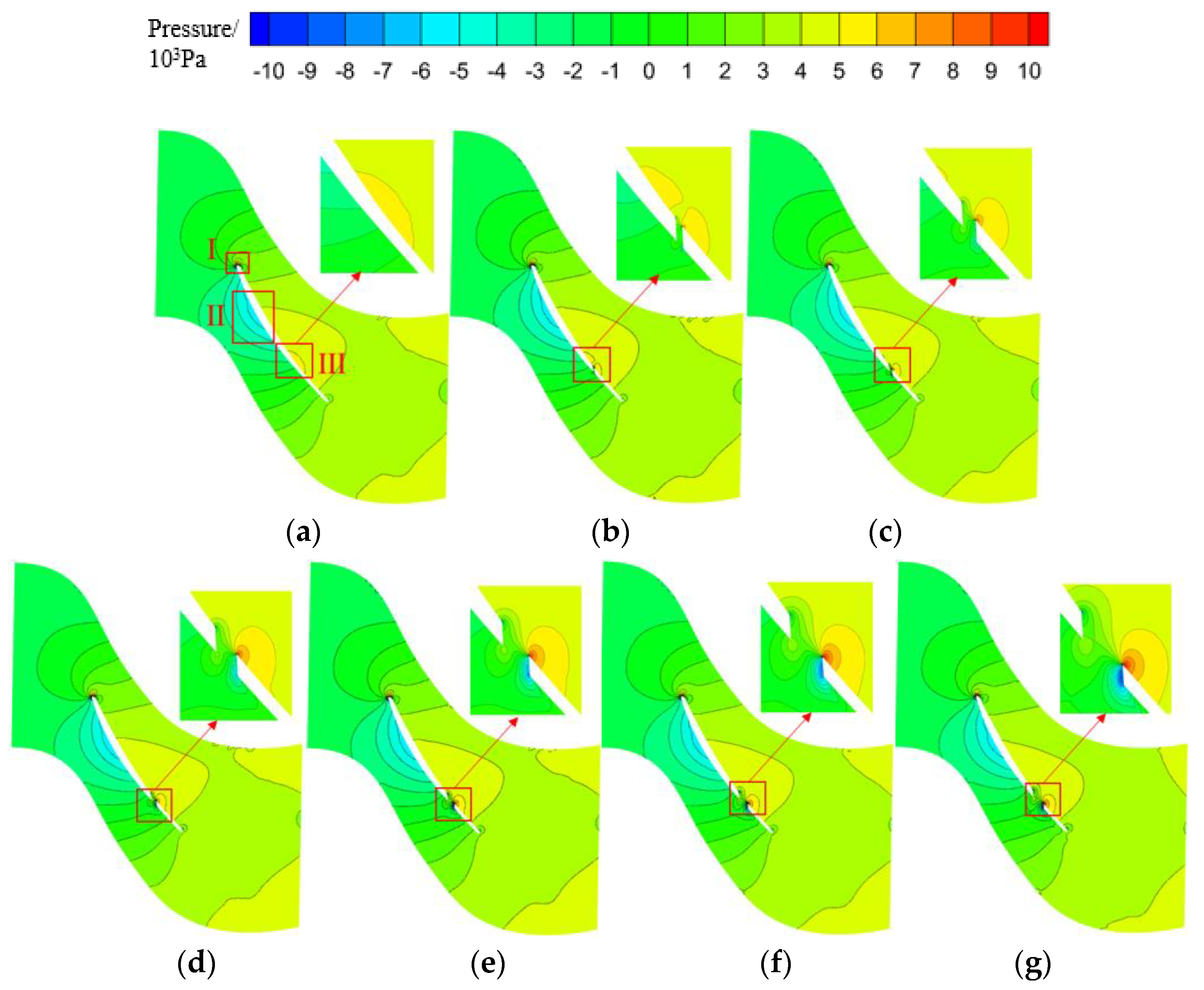
3.2.1. Static Pressure Distribution
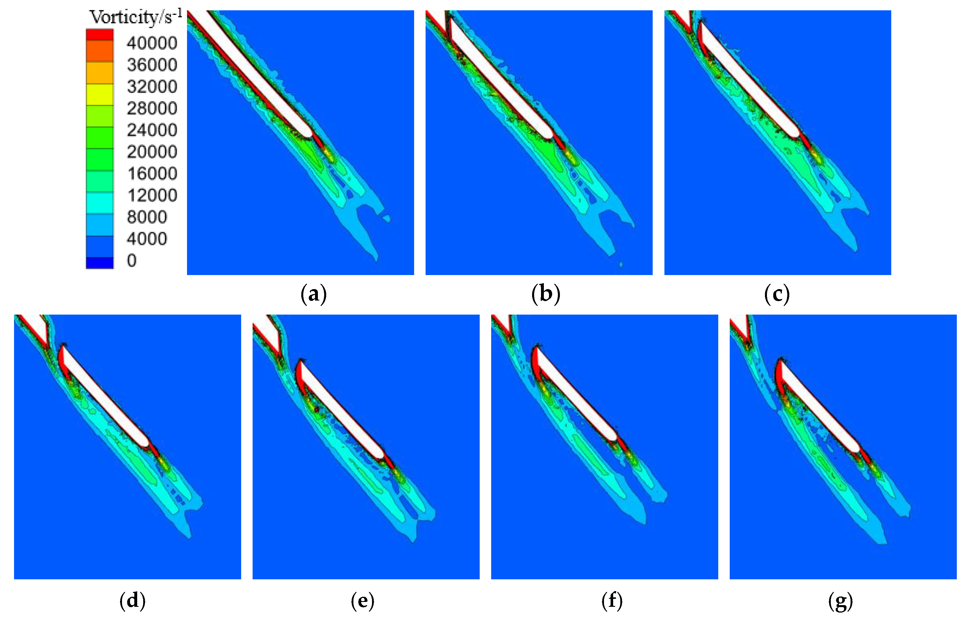
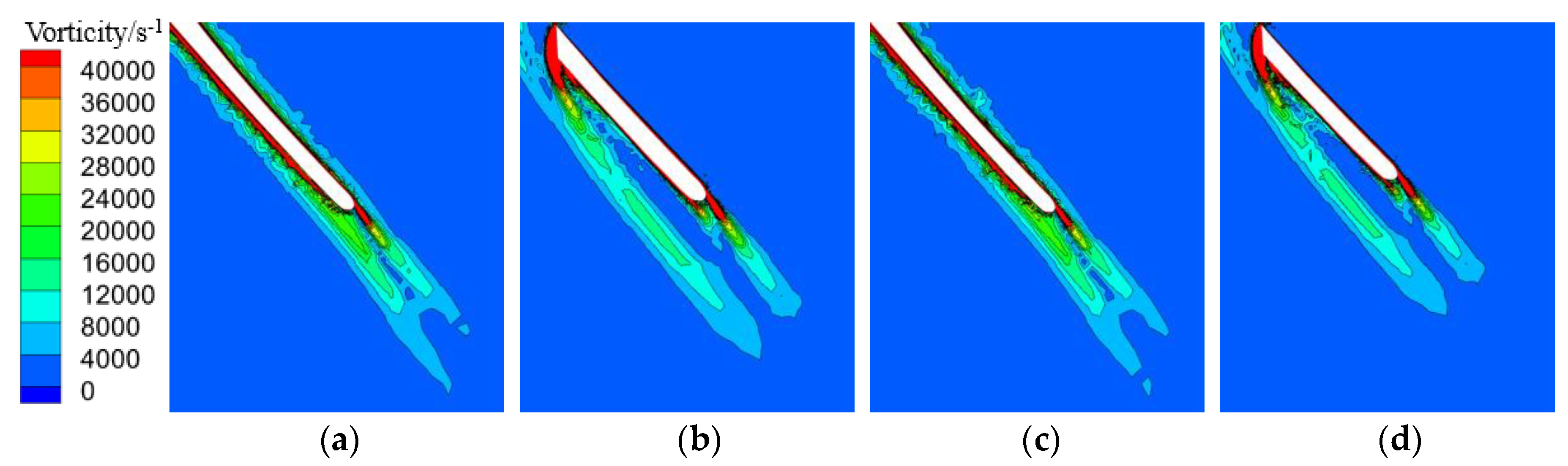
3.2.2. Vorticity Distribution
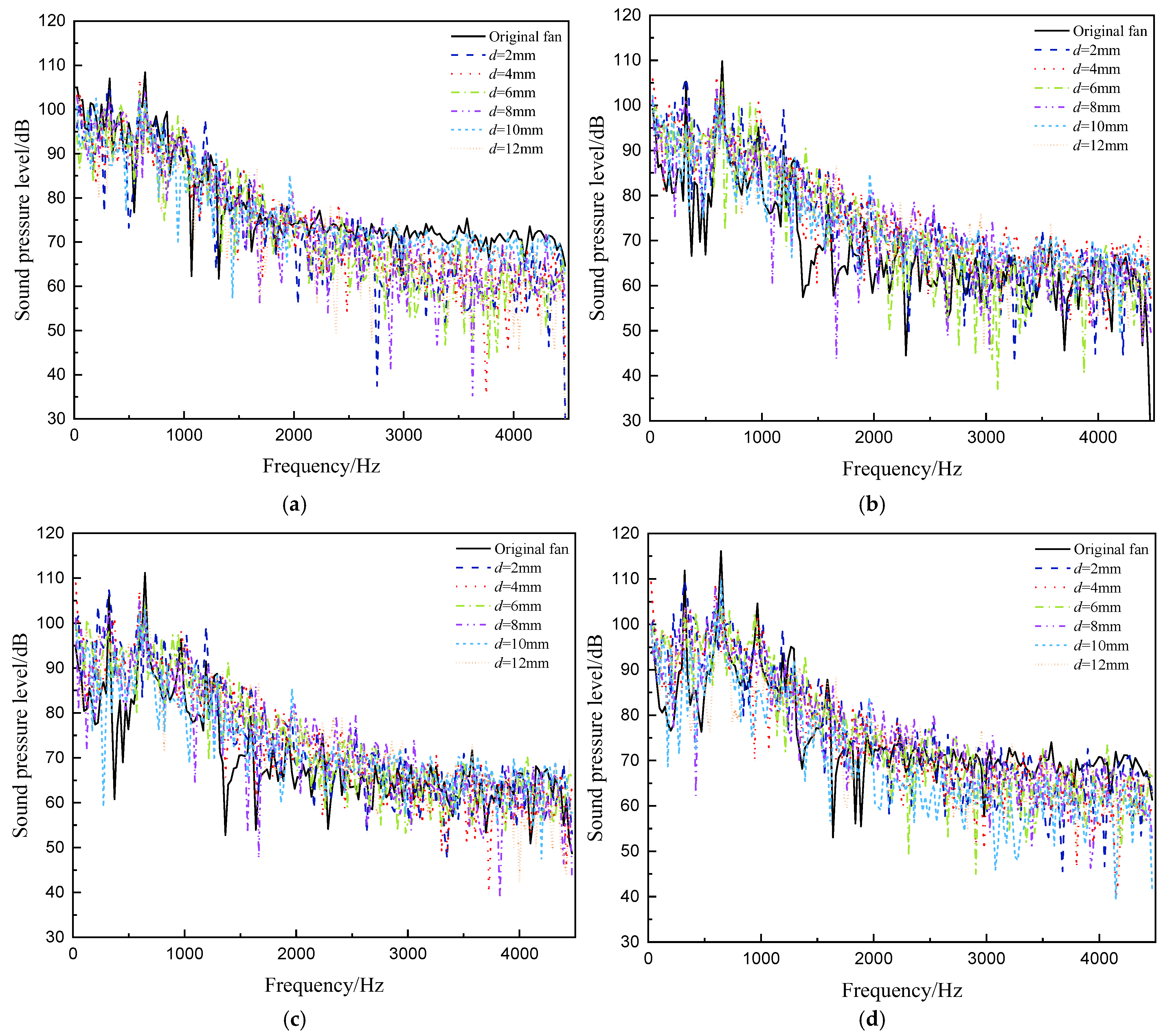
3.3. Noise Distribution
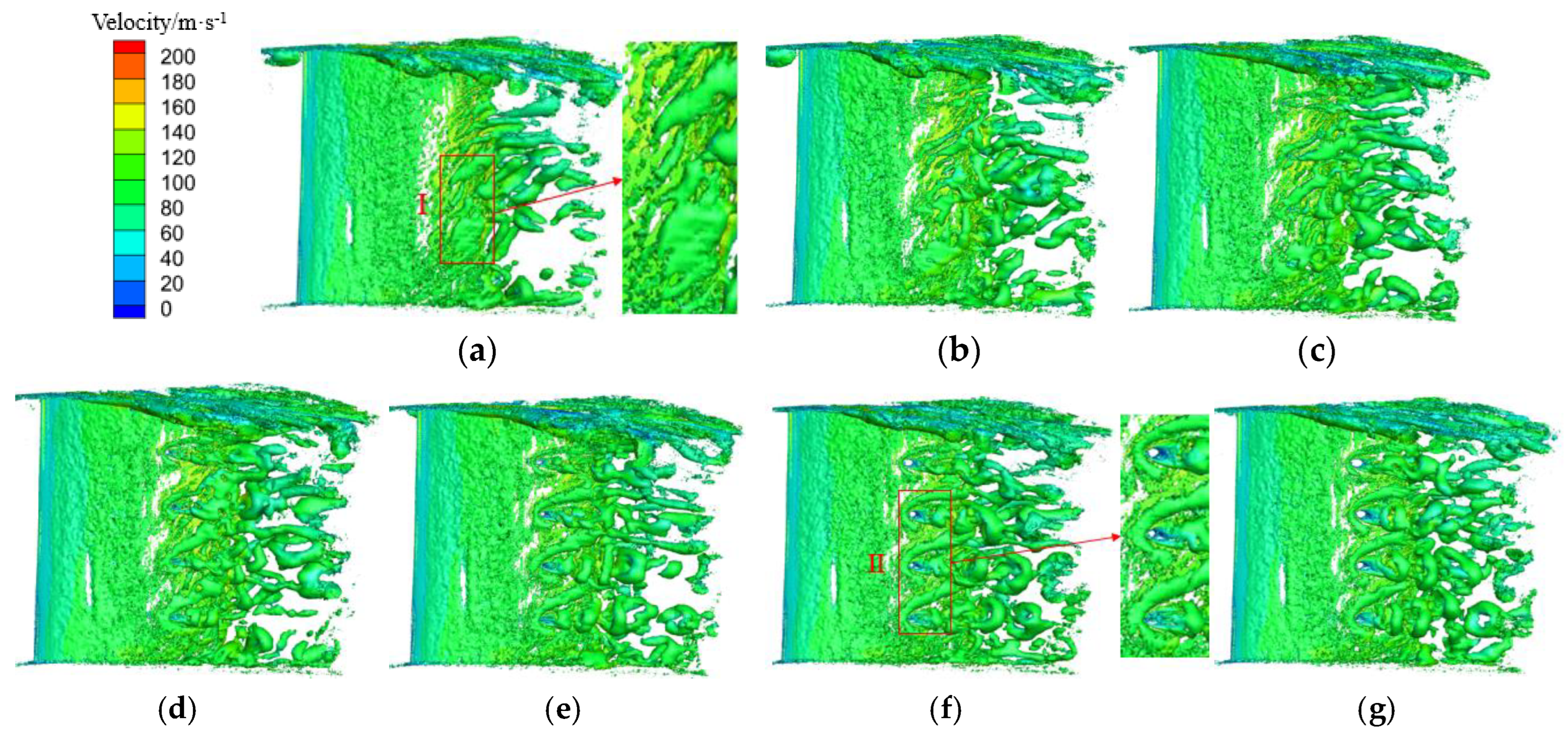
3.4. Vortex Structures
3.5. Different Stages of Blade Perforation
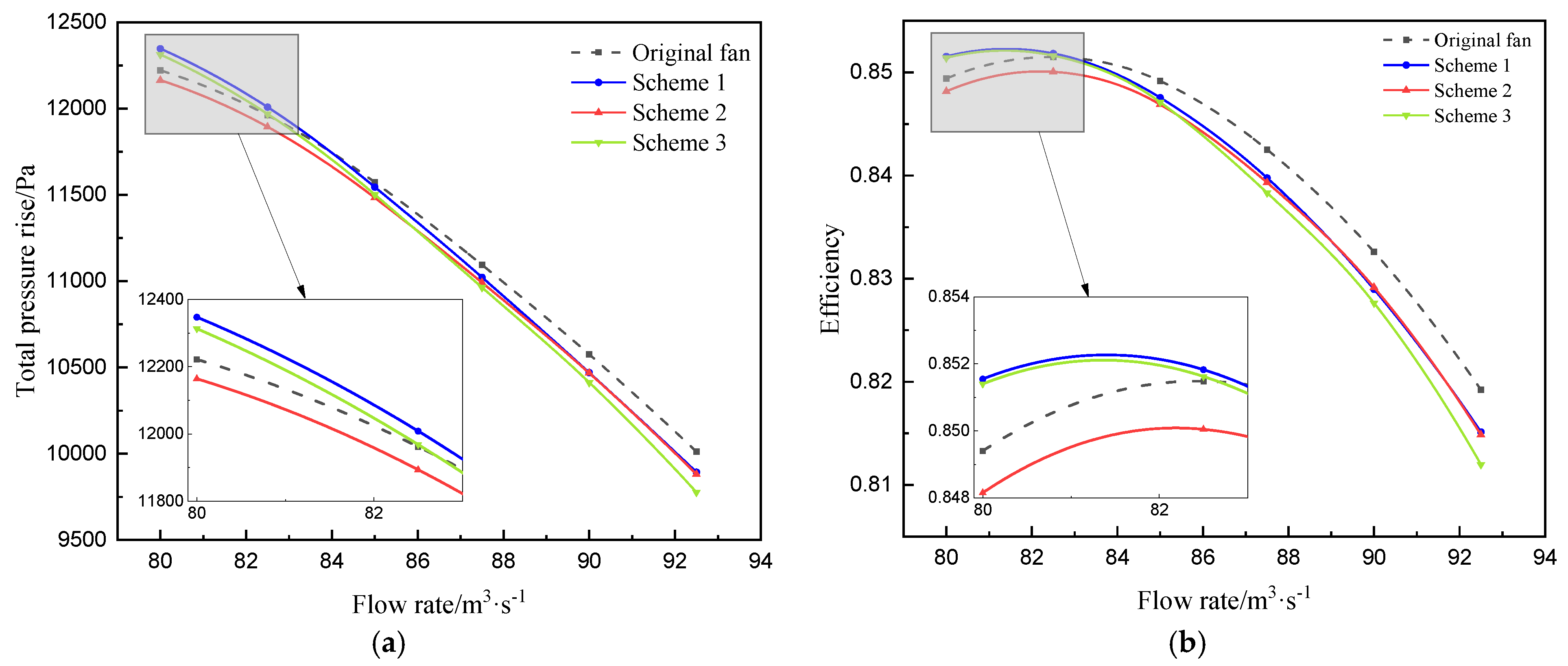
3.5.1. Performance at Different Stages of Blade Perforation
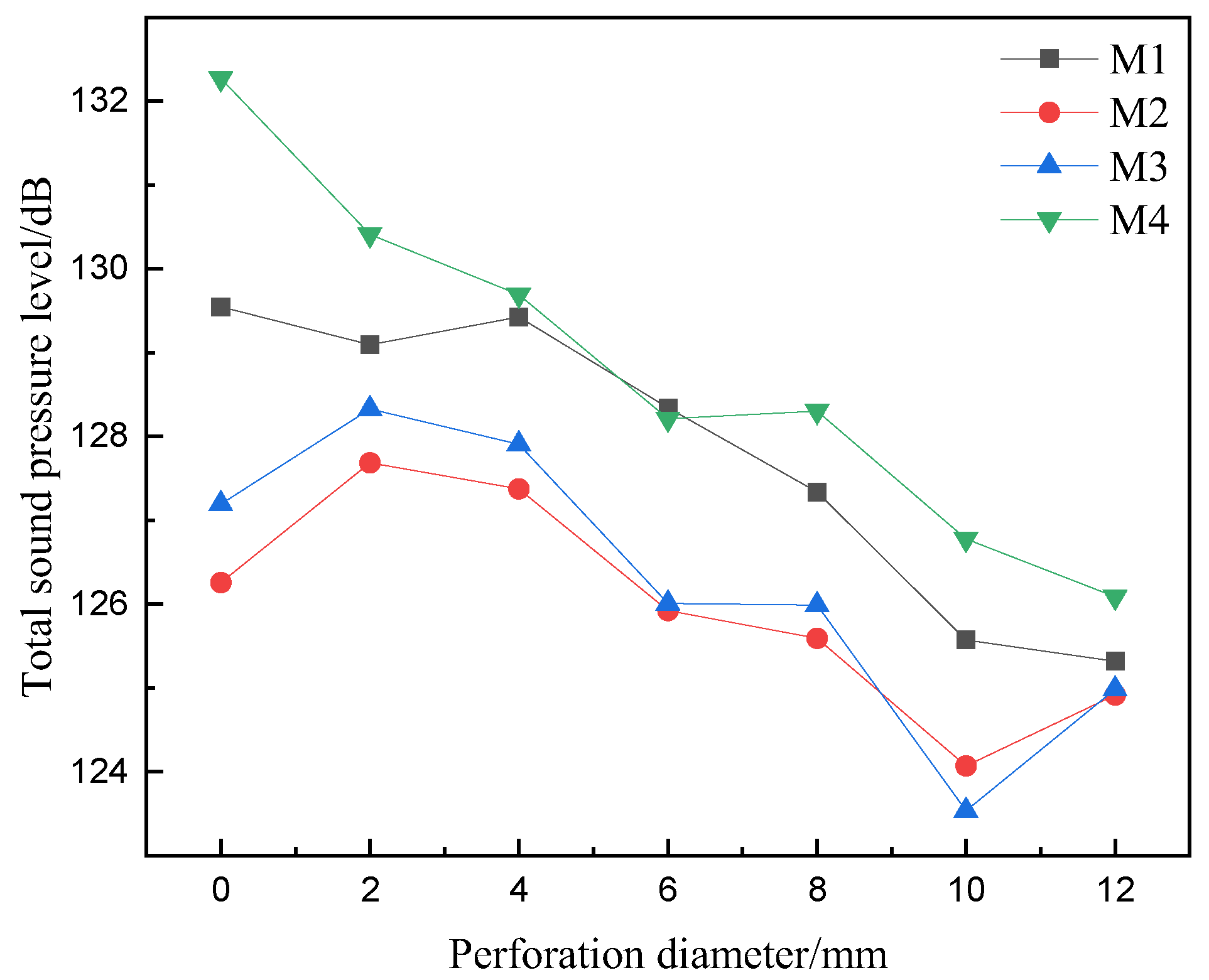
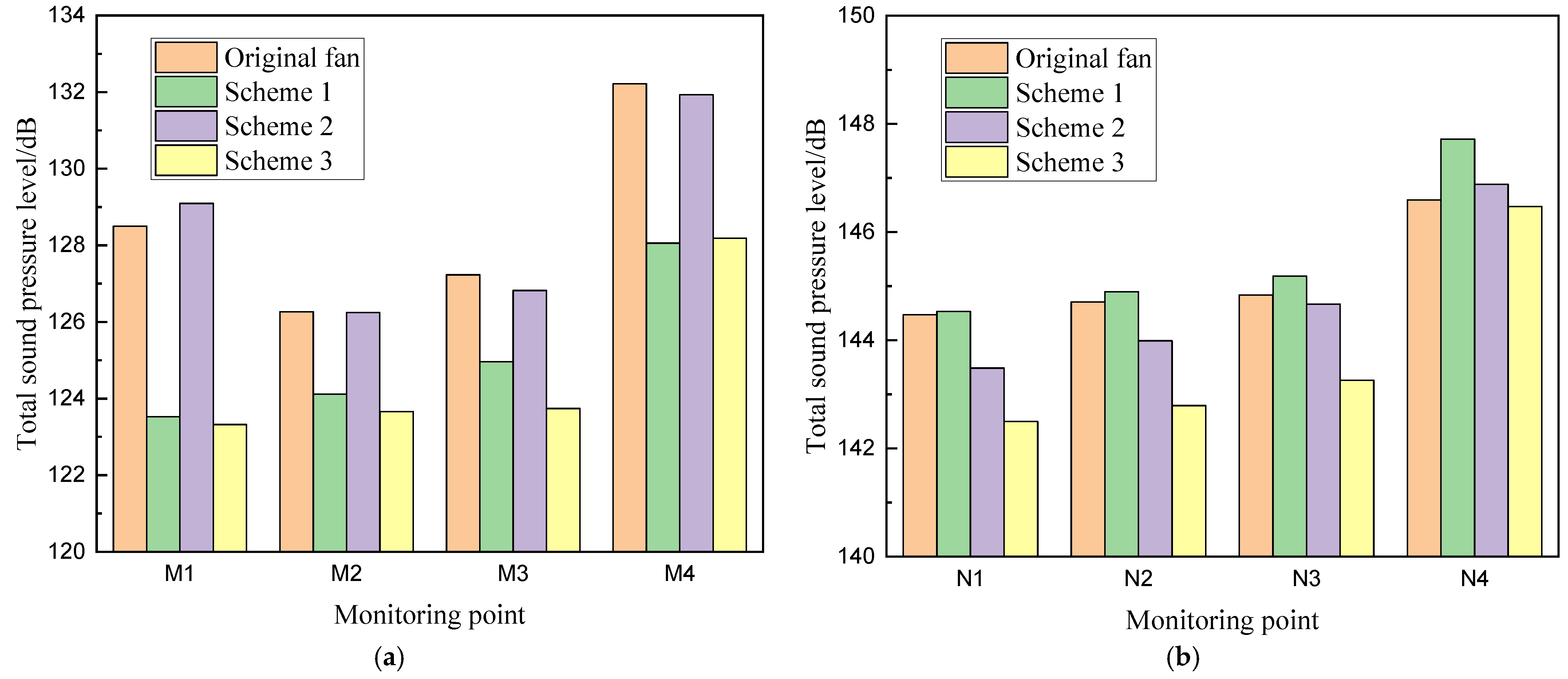
3.5.2. Noise at Different Stages of Blade Perforation
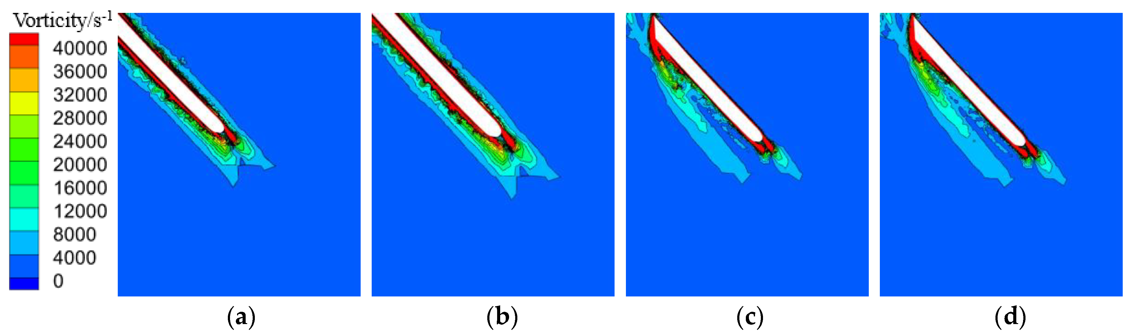
3.5.3. Vorticity Distribution at Different Stages of Blade Perforation
4. Conclusions
Author Contributions
Funding
Data Availability Statement
Conflicts of Interest
Abbreviations
| MRF | Multiple Reference Frame |
| LES | Large eddy simulation |
| CAA | Computational Aeroacoustics |
| FFT | Fast Fourier Transform |
| FW-H | Ffowcs Williams–Hawkings |
| SPL | Sound-pressure level |
References
- Sun, Y.; Li, R.; Wang, L.; Liu, C.; Yang, Z.; Ma, F. Bionic noise reduction design of axial fan impeller. J. Phys. D Appl. Phys. 2024, 57, 345501. [Google Scholar] [CrossRef]
- Ullah, T.; Ahmad, F.; Siddiqi, M.U.R.; Hanif, M.I.; Irfan, M.; Khan, A.H.; Ali, S. Blade meridional profile optimization for novel high-pressure ratio centrifugal compressor design using numerical simulations. In Proceedings of the 2020 3rd International Conference on Computing, Mathematics and Engineering Technologies (iCoMET), Sukkur, Pakistan, 29–30 January 2020; pp. 1–9. [Google Scholar]
- Khan, A.; Irfan, M.; Niazi, U.M.; Shah, I.; Legutko, S.; Rahman, S.; Alwadie, A.S.; Jalalah, M.; Glowacz, A.; Khan, M.K.A. Centrifugal compressor stall control by the application of engineered surface roughness on diffuser shroud using numerical simulations. Materials 2021, 14, 2033. [Google Scholar] [CrossRef] [PubMed]
- Yin, W.; Yang, A.; Chen, E.; Lu, C. Experimental Study on Aerodynamic Noise Characteristics of Bionic Axial Flow Fans. J. Eng. Therm. Energy Power 2022, 37, 51–59. [Google Scholar]
- Kholodov, P.; Moreau, S. Optimization of trailing-edge serrations with and without slits for broadband noise reduction. J. Sound Vib. 2021, 490, 115736. [Google Scholar] [CrossRef]
- Zhou, W.; Zhou, P.; Xiang, C.; Wang, Y.; Mou, J.; Cui, J. A Review of Bionic Structures in Control of Aerodynamic Noise of Centrifugal Fans. Energies 2023, 16, 4331. [Google Scholar] [CrossRef]
- Huang, Q.; Chen, E.; Yang, A.; Liu, J. Experimental Study on Noise Reduction of an Axial Flow Fan with Inclined Serrated Trailing Edge. J. Chin. Soc. Power Eng. 2020, 40, 735–741. [Google Scholar]
- Hickey, J.; Zhao, W.; Persoons, T. Experimental and numerical investigation of winglet designs for optimized performance of small axial fans. Appl. Acoust. 2025, 231, 110448. [Google Scholar] [CrossRef]
- Ryu, S.Y.; Cheong, C.; Kim, J.W.; Park, B.I. Analysis of aerodynamic and aeroacoustic performances of axial flow fans with variable winglet curvature in chordwise direction. Results Eng. 2024, 21, 101857. [Google Scholar] [CrossRef]
- Xu, Z.; Liu, X.; Liu, Y.; Qin, W.; Xi, G. Flow Control Mechanism of Blade Tip Bionic Grooves and Their Influence on Aerodynamic Performance and Noise of Multi-Blade Centrifugal Fan. Energies 2022, 15, 3431. [Google Scholar] [CrossRef]
- Chen, B.; Li, J.; He, J.; Xu, J.; Wang, Y. Influence of blade perforation on acoustic performance of the centrifugal fan. J. Mech. Electr. Eng. 2023, 40, 1267–1275. [Google Scholar]
- Wang, H.; Wang, L.; Liu, H.; Wang, B.; Hu, L. Influence of blade perforation number on aerodynamic performance and noise performance of cooling fan. J. Mech. Electr. Eng. 2024, 41, 302–310. [Google Scholar]
- Yang, X.; Wu, C.; Wen, H.; Zhang, L. Numerical simulation and experimental research on the aerodynamic performance of large marine axial flow fan with a perforated blade. J. Low Freq. Noise Vib. Act. Control 2018, 37, 410–421. [Google Scholar] [CrossRef]
- Hu, Y.J.; Wang, Y.P.; Li, G.Q.; Jin, Y.Z.; Setoguchi, T.; Kim, H.D. Effects of Perforation Number of Blade on Aerodynamic Performance of Dual-rotor Small Axial Flow Fans. J. Therm. Sci. 2015, 24, 123–130. [Google Scholar] [CrossRef]
- Zhang, J.; Sai, Q.; Yan, Y. Effect of Blade Perforation Diameter on Aerodynamic Performance and Noise of Small Axial Fan. J. Chongqing Technol. Bus. Univ. (Nat. Sci. Ed.) 2024, 1–11. [Google Scholar]
- Ma, R. Performance Analysis and Optimal Design of the Hollow Rotor Blades with Trailing Edge Self-induced Blowing. Master’s Thesis, Huazhong University of Science and Technology, Wuhan, China, 2013. [Google Scholar]
- Wang, S.; Yang, A.; Li, G.; Chen, E.; Wu, C. Influence of hole type and incline angle on the aerodynamic and noise characteristics of perforated blade. J. Univ. Shanghai Sci. Technol. 2021, 43, 528–535. [Google Scholar]
- Wang, Z.; He, Y.; Li, M.; Qiu, M.; Huang, C.; Liu, Y.; Wang, Z. Fluid—Structure interaction of two-phase flow passing through 90° pipe bend under slug pattern conditions. China Ocean Eng. 2021, 35, 914–923. [Google Scholar] [CrossRef]
- Liu, X.; Song, L.; Yu, B.; Tao, Z.; Li, J. Large Eddy Simulation of Flow Resistance and Heat Transfer Characteristics of Dual-Swirl Cooling on Turbine Blade Leading Edge. J. Xi’an Jiaotong Univ. 2025, 59, 34–45. [Google Scholar]
- Su, Z.; Liu, E.; Xu, Y.; Xie, P.; Shang, C.; Zhu, Q. Flow field and noise characteristics of manifold in natural gas transportation station. Oil Gas Sci. Technol. 2019, 74, 70. [Google Scholar] [CrossRef]
- Yang, T.; Ye, X.; Liu, Y.; Li, C. Numerical Study on the Influence of Blade Tip Slot and Winglet on the Performance and Noise of Axial Fans. J. Chin. Soc. Power Eng. 2023, 43, 1123–1131. [Google Scholar]
- Yang, W.; Wang, Y.; Sui, D.; Li, J.; Gao, J. Research on aerodynamic performance and noise reduction of non-uniform serrated trailing edges for an axial compressor. Phys. Fluids 2025, 37, 034112. [Google Scholar] [CrossRef]
- Zheng, N.; Ye, X.; Hu, J.; Li, C. Effect of Toothed Flap Trailing Edge Blades on the Aerodynamic Noise of an Axial Fan. J. Eng. Therm. Energy Power 2022, 37, 50–58. [Google Scholar]
- Hunt, J.C.R.; Wray, A.A.; Moin, P. Eddies, Streams, and Convergence Zones in Turbulent Flows; Center for Turbulence Research: Stanford, CA, USA, 1988; pp. 193–208. [Google Scholar]
- Ye, X.; Zhang, R.; Zhang, C.; Li, C. Aeroacoustics and Performance of an Axial-flow Fan with Serrated Trailing Edge Blades. J. Chin. Soc. Power Eng. 2020, 40, 239–246. [Google Scholar]

| Parameters | Values |
|---|---|
| Design total pressure rise/Pa | 11,865 |
| Design efficiency/% | 88.3 |
| Design volumetric flow rate/(m3 s−1) | 82.5 |
| Impeller diameter/mm | 1778 |
| Tip clearance/mm | 4 |
| Tip chord length of rotor blade/mm | 192 |
| Mid-span chord length of rotor blade/mm | 198 |
| Root chord length of rotor blade/mm | 202 |
| Tip setting angle of rotor blade/(°) | 31.7 |
| Mid-span setting angle of rotor blade/(°) | 39.1 |
| Root setting angle of rotor blade/(°) | 54.5 |
| Parameters | Original Fan Model | d = 30 Fan Model | Increment |
|---|---|---|---|
| Grid Refinement Factor | 1.2 | 1.2 | 1.2 |
| Total Pressure Rise under Fine Grid | 11,962 | 12,008 | 46 |
| Total Pressure Rise under Medium Grid | 12,007 | 12,055 | 48 |
| Total Pressure Rise under Coarse Grid | 12,092 | 12,146 | 54 |
| Key Variable Extrapolated Value | 11,911.4 | 11,957 | 45.3 |
| Extrapolated Value Relative Error/% | 0.423 | 0.427 | 3.034 |
| Grid Convergence Index/% | 0.529 | 0.533 | 3.793 |
Disclaimer/Publisher’s Note: The statements, opinions and data contained in all publications are solely those of the individual author(s) and contributor(s) and not of MDPI and/or the editor(s). MDPI and/or the editor(s) disclaim responsibility for any injury to people or property resulting from any ideas, methods, instructions or products referred to in the content. |
© 2025 by the authors. Licensee MDPI, Basel, Switzerland. This article is an open access article distributed under the terms and conditions of the Creative Commons Attribution (CC BY) license (https://creativecommons.org/licenses/by/4.0/).
Share and Cite
Qiao, C.; Ye, X.; Wu, Y.; Li, C. Insight into the Impact of Blade Perforation on the Aerodynamics and Acoustics of a Two-Stage Variable-Pitch Axial Fan. Energies 2025, 18, 1966. https://doi.org/10.3390/en18081966
Qiao C, Ye X, Wu Y, Li C. Insight into the Impact of Blade Perforation on the Aerodynamics and Acoustics of a Two-Stage Variable-Pitch Axial Fan. Energies. 2025; 18(8):1966. https://doi.org/10.3390/en18081966
Chicago/Turabian StyleQiao, Chen, Xuemin Ye, Yunhao Wu, and Chunxi Li. 2025. "Insight into the Impact of Blade Perforation on the Aerodynamics and Acoustics of a Two-Stage Variable-Pitch Axial Fan" Energies 18, no. 8: 1966. https://doi.org/10.3390/en18081966
APA StyleQiao, C., Ye, X., Wu, Y., & Li, C. (2025). Insight into the Impact of Blade Perforation on the Aerodynamics and Acoustics of a Two-Stage Variable-Pitch Axial Fan. Energies, 18(8), 1966. https://doi.org/10.3390/en18081966