
Strengthening Low-Voltage Ride Through Competency of Doubly Fed Induction Generator Driven by Wind Turbine Using Super-Twisting Sliding Mode Control


Abstract
1. Introduction
- Enhancing the LVRT capacity of the DFIG-based WT by using STSMC and without inserting any external device.
- The Arctic Puffin optimizer (APO) is used to calculate the optimal sliding surface required for super-twisting control.
- The APO is also used to find the best parameters for a PI controller compared to the proposed controller.
- The suggested controllers are implemented entirely in the Simulink/MATLAB environment version 2024b.
2. The Mathematical Model of DFIG
3. Sliding Mode Control
3.1. Super-Twisting
3.2. The Control Law
4. Arctic Puffin Optimizer
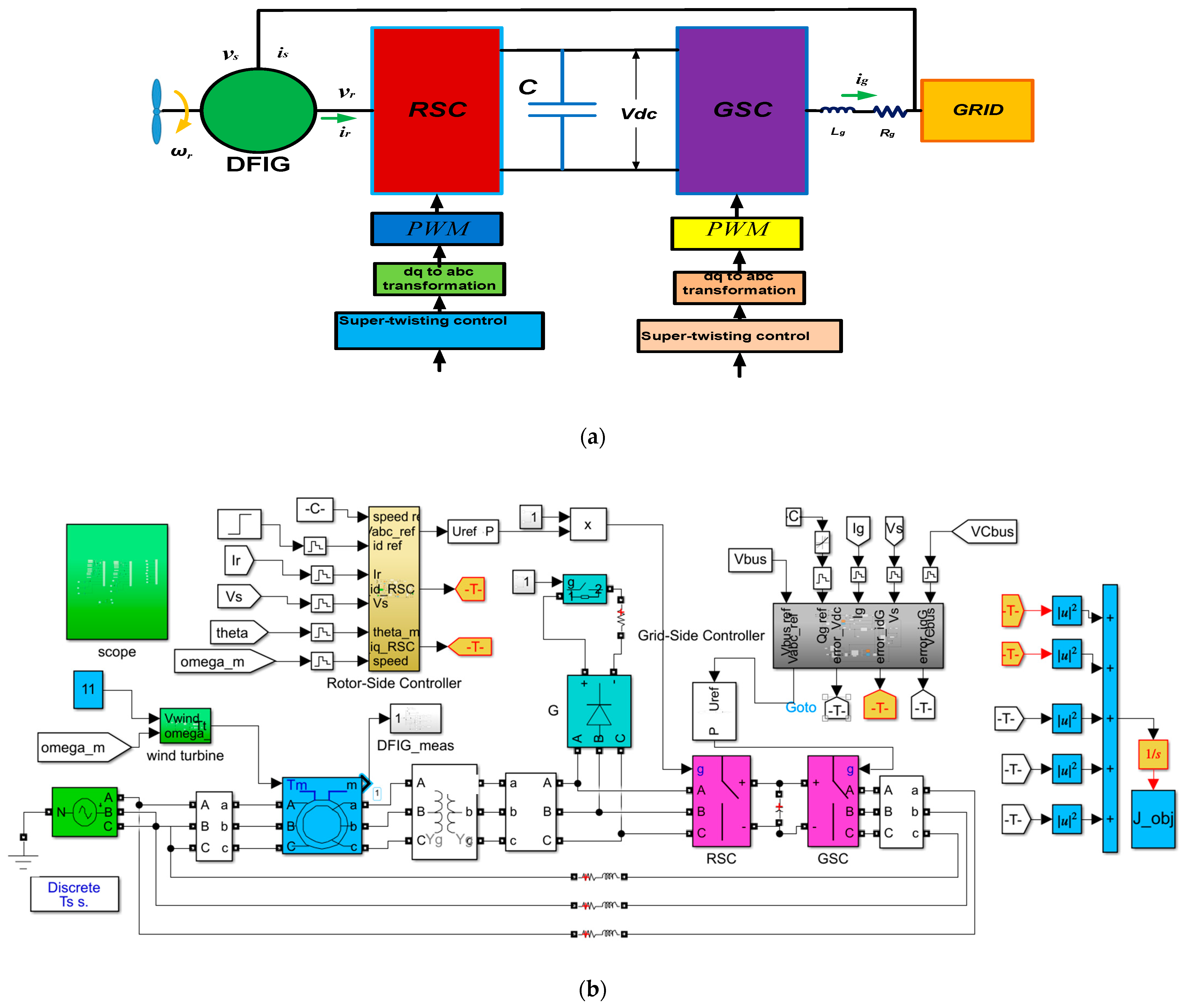
5. The Studied System
5.1. RSC Controller
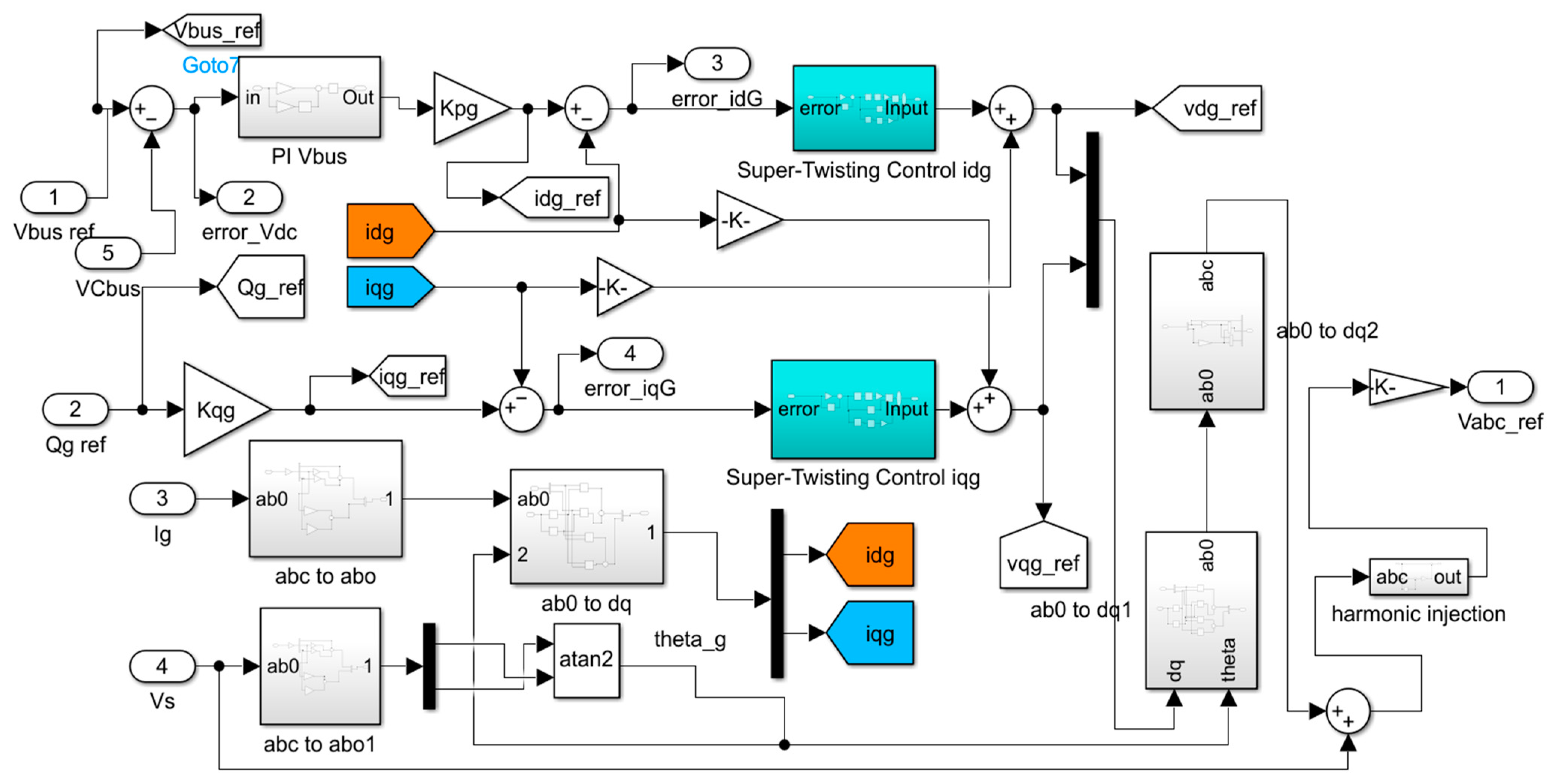
5.2. GSC Controller
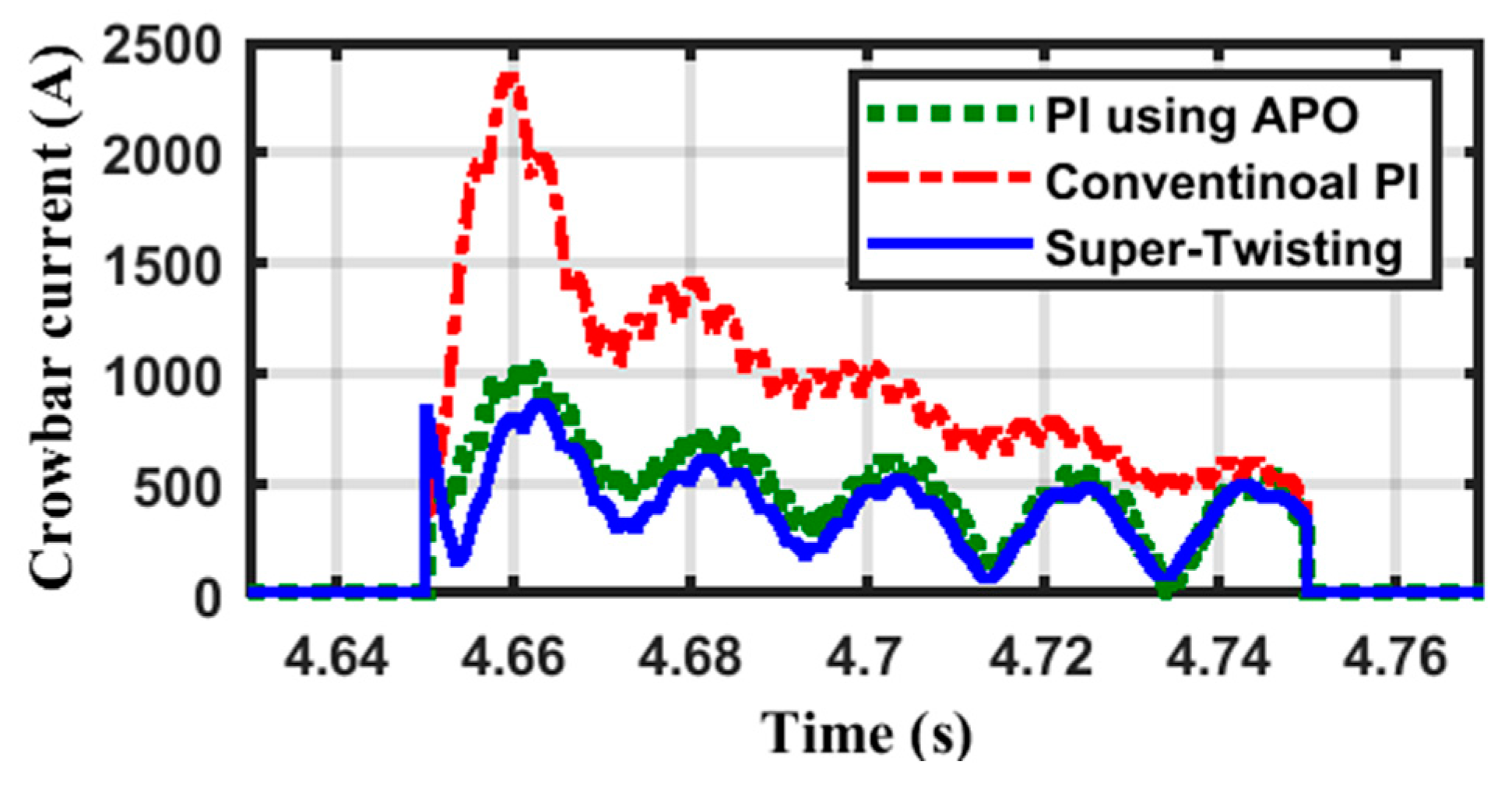
5.3. The Crowbar Circuit
5.4. Wind Turbine Control
6. Simulation Results
7. Conclusions
Author Contributions
Funding
Data Availability Statement
Conflicts of Interest
Abbreviations
| DFIG | Doubly fed induction generator |
| STSMC | Super-twisting sliding mode control |
| APO | Arctic Puffin optimizer |
| WTs | Wind turbines |
| LVRT | Low-voltage ride through |
| VD | Voltage dip |
| RefF | Reference frame |
| STV | Stator voltage |
| ROV | Rotor voltage |
| STFL | Stator flux |
| ROFL | Rotor flux |
| MPPT | Maximum power point |
| STW | Super-twisting |
| RSC | Rotor-side converter |
| GRS | Grid-side converter |
| CB | Crowbar |
Appendix A

| Turbine Data | ||
| Parameter | Magnitude | Units |
| Axle inertia at low speed values | 800.0 | Kg.m2 |
| Axle friction at low speed values | 0.10 | Nm.s/rad |
| Stiffness factor | 12500.0 | Nm/rad |
| Damping factor | 1300.0 | Nm.s/rad |
| Axle inertia at high speed values | 90.0 | Kg.m2 |
| Axle friction at high speed values | 0.10 | Nm.s/rad |
| Data of the Generator | ||
| Parameter | Magnitude | Units |
| The nameplate-rated active power | 2.00 | MW. |
| The nameplate-rated torque | 12732.0 | Nm. |
| Rated voltage of the stator windings | 690.0 | Volts |
| Rated speed | 1500.0 | rpm. |
| Speed range | 900.0–2000.0 | rpm. |
| Pole pairs | 2.0 | |
| Mutual inductance, | 2.50 | mH. |
| Leakage inductance of the rotor, | 87.0 | μH. |
| Leakage inductance of the Stator, | 87.0 | μH. |
| Rotor resistance, | 0.0260 | Ω. |
| Stator resistance, | 0.0290 | Ω. |
| Stator/rotor turns ratio | 1/3 | |
| Maximum slip | 1/3 | |
References
- Badawi, A.; Soliman, M.; Elzein, I.M.; Alqaisi, W. Optimizing Low-Voltage Ride-Through in DFIG Wind Turbines via QPQC-Based Predictive Control for Grid Compliance. Int. J. Robot. Control Syst. 2025, 5, 86–104. [Google Scholar]
- Loulijat, A.; Hilali, A.; Makhad, M.; Chojaa, H.; Ababssi, N.; Mossa, M.A. Low-voltage ride-through capability of DFIG-based WECS improved by nonlinear backstepping controller synthesized in novel power state model. E-Prime-Adv. Electr. Eng. Electron. Energy 2025, 11, 100864. [Google Scholar]
- Ullah, A.; Ullah, S.; Rahman, T.U.; Sami, I.; Rahman, A.U.; Alghamdi, B.; Pan, J. Enhanced wind energy conversion system performance using fast smooth second-order sliding mode control with neuro-fuzzy estimation and variable-gain robust exact output differentiator. Appl. Energy 2025, 377, 124364. [Google Scholar]
- Fouad, A.; Kotb, H.; AboRas, K.M.; ElRefaie, H.B.; Alqarni, M.; Baqasah, A.M.; Yakout, A.H. Enhancing grid-connected DFIG’s LVRT capability using dandelion optimizer based the hybrid fractional-order PI and PI controlled STATCOM. IEEE Access 2024, 12, 120181–120197. [Google Scholar]
- Yang, Z.; Gao, B.; Cao, Z. Low-voltage ride-through strategy for offshore wind turbines based on current relaxation region. Electr. Power Syst. Res. 2023, 223, 109704. [Google Scholar]
- Mostafa, M.A.; El-Hay, E.A.; Elkholy, M.M. An overview and case study of recent low voltage ride through methods for wind energy conversion system. Renew. Sustain. Energy Rev. 2023, 183, 113521. [Google Scholar]
- Molina, M.G.; Alvarez, J.M.G. Technical and Regulatory Exigencies for Grid Connection of Wind Generation. In Wind Farm; Gastón, O.S., Ed.; IntechOpen: London, UK, 2011; p. 29. [Google Scholar]
- Erlich, I.; Bachmann, U. Grid code requirements concerning connection and operation of wind turbines in Germany. In Proceedings of the IEEE Power Engineering Society General Meeting 2005, San Francisco, CA, USA, 16 June 2005; IEEE: New York, NY, USA, 2005. [Google Scholar]
- Moheb, A.M.; El-Hay, E.A.; El-Fergany, A.A. Comprehensive review on fault ride-through requirements of renewable hybrid microgrids. Energies 2022, 15, 6785. [Google Scholar] [CrossRef]
- Yameen, M.Z.; Lu, Z.; Rao, M.A.A.; Mohammad, A.; Nasimullah; Younis, W. Improvement of LVRT capability of grid-connected wind-based microgrid using a hybrid GOA-PSO-tuned STATCOM for adherence to grid standards. IET Renew. Power Gener. 2024, 18, 3218–3238. [Google Scholar]
- Gupta, S.; Shukla, A.; Abusara, M. DFIG Driven Wind Turbine with Grid Supporting Battery Storage System. IEEE Trans. Ind. Electron. 2024, 72, 1537–1548. [Google Scholar]
- Code, D.G. Grid Code. 2005. Available online: https://www.scribd.com/document/495816846/Grid-Code-2005-1 (accessed on 21 November 2024).
- Joshi, J.; Swami, A.K.; Jately, V.; Azzopardi, B. A Comprehensive Review of Control Strategies to Overcome Challenges During LVRT in PV Systems. IEEE Access 2021, 9, 121804–121834. [Google Scholar]
- Moheb, A.M.; El-Hay, E.A.; El-Fergany, A.A. Consolidation of LVFRT capabilities of microgrids using energy storage devices. Sci. Rep. 2023, 13, 22294. [Google Scholar] [CrossRef]
- Abad, G.; Lopez, J.; Rodriguez, M.; Marroyo, L.; Iwanski, G. Doubly Fed Induction Machine: Modeling and Control for Wind Energy Generation; John Wiley & Sons: Hoboken, NJ, USA, 2011. [Google Scholar]
- Gomis-Bellmunt, O.; Junyent-Ferre, A.; Sumper, A.; Bergas-Jane, J. Ride-Through Control of a Doubly Fed Induction Generator Under Unbalanced Voltage Sags. IEEE Trans. Energy Convers. 2008, 23, 1036–1045. [Google Scholar] [CrossRef]
- Nasiri, M.; Milimonfared, J.; Fathi, S.H. A review of low-voltage ride-through enhancement methods for permanent magnet synchronous generator based wind turbines. Renew. Sustain. Energy Rev. 2015, 47, 399–415. [Google Scholar] [CrossRef]
- Tsili, M.; Papathanassiou, S. A review of grid code technical requirements for wind farms. IET Renew. Power Gener. 2009, 3, 308–332. [Google Scholar] [CrossRef]
- Rezaie, H.; Kazemi-Rahbar, M.H. Enhancing voltage stability and LVRT capability of a wind-integrated power system using a fuzzy-based SVC. Eng. Sci. Technol. Int. J. 2019, 22, 827–839. [Google Scholar] [CrossRef]
- Stalin Kumar Samal, R.T.; Karad, S. STATCOM with Fuzzy-PI Controller for Low Voltage-Ride through Enhancement of DFIG based Wind Farm. Int. J. Emerg. Trends Eng. Res. 2021, 9, 518–523. [Google Scholar]
- Lella, K.; Mohan, N.R. Application of Bridge Type Fault Current Limiter for Fault Ride-Through Capability Enhancement of Dfig Based Variable Speed Wind Turbines. J. Electr. Eng. 2017, 17, 8. [Google Scholar]
- Alaboudy, A.H.K.; Mahmoud, H.A.; Elbaset, A.A.; Abdelsattar, M. Technical Assessment of the Key LVRT Techniques for Grid-Connected DFIG Wind Turbines. Arab. J. Sci. Eng. 2023, 48, 15223–15239. [Google Scholar] [CrossRef]
- Saeed, S.; Asghar, R.; Mehmood, F.; Saleem, H.; Azeem, B.; Ullah, Z. Evaluating a Hybrid Circuit Topology for Fault-Ride through in DFIG-Based Wind Turbines. Sensors 2022, 22, 9314. [Google Scholar] [CrossRef]
- Joshiram, T.; Kumari, S.L. Power Quality Enhancement and Low Voltage Ride Through Capability in Hybrid Grid Interconnected System by Using D-Fact Devices. In Emerging Technologies for Computing, Communication and Smart Cities; Springer Nature: Singapore, 2022. [Google Scholar]
- Hassanein, W.S.; Ahmed, M.M.; Abed el-Raouf, M.O.; Ashmawy, M.G.; Mosaad, M.I. Performance improvement of off-grid hybrid renewable energy system using dynamic voltage restorer. Alex. Eng. J. 2020, 59, 1567–1581. [Google Scholar] [CrossRef]
- Endale, S.M.; Tuka, M.B. Fault Ride through Capability Analysis of Wind Turbine with Doubly Fed Induction Generator. Preprints 2021. [Google Scholar] [CrossRef]
- Haque, M.H. Compensation of distribution system voltage sag by DVR and D-STATCOM. In Proceedings of the 2001 IEEE Porto Power Tech Proceedings (Cat. No.01EX502), Porto, Portugal, 10–13 September 2001; IEEE: New York, NY, USA, 2001; Volume 1, p. 5. [Google Scholar]
- Vilathgamuwa, D.M.; Gajanayake, C.J.; Loh, P.C.; Li, Y.W. Voltage Sag Compensation with Z-Source Inverter Based Dynamic Voltage Restorer. In Proceedings of the Conference Record of the 2006 IEEE Industry Applications Conference Forty-First IAS Annual Meeting, Tampa, FL, USA, 8–12 October 2006; IEEE: New York, NY, USA, 2006; pp. 2242–2248. [Google Scholar]
- Gayathri, K.; Jeevananthan, S. Refined vector control structure and indirect MPPT for grid connected DFIG-based wind energy conversion system, and appraisal on matrix converter interface. Int. J. Model. Identif. Control 2024, 44, 255–282. [Google Scholar] [CrossRef]
- Moumani, Y.; Laafou, A.J.; Ait Madi, A.; Boutssaid, R. An improved dual vector control for a doubly fed induction generator based wind turbine during asymmetrical voltage dips. Bull. Electr. Eng. Inform. 2024, 13, 3757–3769. [Google Scholar] [CrossRef]
- Thet, A.K.; Saitoh, H. Pitch control for improving the low-voltage ride-through of wind farm. In Proceedings of the 2009 Transmission & Distribution Conference & Exposition: Asia and Pacific, Seoul, Republic of Korea, 26–30 October 2009; IEEE: New York, NY, USA, 2009. [Google Scholar]
- Zhu, J.H.; Zhang, P.; Zhang, X.; Qin, L.; Sun, C.; Li, H. Model Predictive Control on Transient Flux Linkage and Reactive Power Compensation of Doubly Fed Induction Wind Generator. Int. J. Energy Res. 2024, 2024, 6648691. [Google Scholar] [CrossRef]
- Achar, A.; Djeriri, Y.; Benbouhenni, H.; Bouddou, R.; Elbarbary, Z.M.S. Modified Vector-Controlled DFIG Wind Energy System Using Robust Model Predictive Rotor Current Control. Arab. J. Sci. Eng. 2024, 50, 1–25. [Google Scholar] [CrossRef]
- Hiremath, R.; Moger, T. Improving the DC-Link Voltage of DFIG Driven Wind System Using Modified Sliding Mode Control. Distrib. Gener. Altern. Energy J. 2023, 38, 715–742. [Google Scholar] [CrossRef]
- Rafiee, Z.; Heydari, R.; Rafiee, M.; Aghamohammadi, M.R.; Blaabjerg, F. Enhancement of the LVRT capability for DFIG-based wind farms based on short-circuit capacity. IEEE Syst. J. 2022, 16, 3237–3248. [Google Scholar] [CrossRef]
- Han, Y.; Feng, Y.; Yang, P.; Xu, L.; Xu, Y.; Blaabjerg, F. Cause, Classification of Voltage Sag, and Voltage Sag Emulators and Applications: A Comprehensive Overview. IEEE Access 2020, 8, 1922–1934. [Google Scholar] [CrossRef]
- Herzog, F.; Röder, J.; Frehn, A.; Ruhe, N.; De Doncker, R.W. Influences on the LVRT behavior of DFIG wind turbine systems. In Journal of Physics: Conference Series; IOP Publishing: Bristol, UK, 2022. [Google Scholar]
- Ghaffarzadeh, H.; Mehrizi-Sani, A. Review of Control Techniques for Wind Energy Systems. Energies 2020, 13, 6666. [Google Scholar] [CrossRef]
- Qin, B.; Li, H.; Zhou, X.; Li, J.; Liu, W. Low-Voltage Ride-Through Techniques in DFIG-Based Wind Turbines: A Review. Appl. Sci. 2020, 10, 2154. [Google Scholar] [CrossRef]
- Mahela, O.P.; Gupta, N.; Khosravy, M.; Patel, N. Comprehensive Overview of Low Voltage Ride Through Methods of Grid Integrated Wind Generator. IEEE Access 2019, 7, 99299–99326. [Google Scholar] [CrossRef]
- Gurumurthy, G.; Das, D.K. Terminal sliding mode disturbance observer based adaptive super twisting sliding mode controller design for a class of nonlinear systems. Eur. J. Control 2021, 57, 232–241. [Google Scholar] [CrossRef]
- Utkin, V.; Lee, H. Chattering Problem in Sliding Mode Control Systems. In Proceedings of the International Workshop on Variable Structure Systems, Alghero, Sardinia, 5–7 June 2006; IEEE: New York, NY, USA, 2006; pp. 346–350. [Google Scholar]
- Gambhire, S.J.; Kishore, D.R.; Londhe, P.S.; Pawar, S.N. Review of sliding mode based control techniques for control system applications. Int. J. Dyn. Control 2021, 9, 363–378. [Google Scholar] [CrossRef]
- Komurcugil, H.; Biricik, S.; Bayhan, S.; Zhang, Z. Sliding Mode Control: Overview of Its Applications in Power Converters. IEEE Ind. Electron. Mag. 2021, 15, 40–49. [Google Scholar] [CrossRef]
- Dong, C.S.T.; Nguyen, Q.T.; Nguyen, D.Q.; Vo, H.H.; Tran, T.C.; Brandstetter, P. PMSM Drive with Sliding Mode Direct Torque Control. In AETA 2022—Recent Advances in Electrical Engineering and Related Sciences: Theory and Application; Springer Nature: Singapore, 2024. [Google Scholar]
- Tian, L.; Wei, Q.; Zheng, Q.; Li, H. Convergence rate sliding mode control of permanent magnet synchronous motor based on expanded sliding mode observer. J. Eng. Appl. Sci. 2024, 71, 213. [Google Scholar] [CrossRef]
- Rehan, A.; Boiko, I.; Zweiri, Y. Chaotic Chattering in Sliding Mode Control Systems. IEEE Trans. Autom. Control 2024, 69, 7925–7931. [Google Scholar] [CrossRef]
- Kumari, S.; Pathak, P.K. A State-of-the-Art Review on Recent Load Frequency Control Architectures of Various Power System Configurations. Electr. Power Compon. Syst. 2024, 52, 722–765. [Google Scholar] [CrossRef]
- Poznyak, A.S.; Orlov, Y.V. Vadim I. Utkin and sliding mode control. J. Frankl. Inst. 2023, 360, 12892–12921. [Google Scholar] [CrossRef]
- Abdelaal, A.K.; Shaheen, A.M.; El-Fergany, A.A.; Alqahtani, M.H. Sliding mode control based dynamic voltage restorer for voltage sag compensation. Results Eng. 2024, 24, 102936. [Google Scholar] [CrossRef]
- Abdelaal, A.K.; El-Hameed, M.A. Application of Robust Super Twisting to Load Frequency Control of a Two-Area System Comprising Renewable Energy Resources. Sustainability 2024, 16, 5558. [Google Scholar] [CrossRef]
- Wang, W.C.; Tian, W.C.; Xu, D.M.; Zang, H.F. Arctic puffin optimization: A bio-inspired metaheuristic algorithm for solving engineering design optimization. Adv. Eng. Softw. 2024, 195, 103694. [Google Scholar] [CrossRef]
- Burnham, K.K.; Burnham, J.L.; Johnson, J.A.; Huffman, A. Migratory movements of Atlantic puffins Fratercula arctica naumanni from high Arctic Greenland. PLoS ONE 2021, 16, e0252055. [Google Scholar] [CrossRef] [PubMed]


| Supper Twisting | Conventional PI | APO | ||||||||||
|---|---|---|---|---|---|---|---|---|---|---|---|---|
| Direct Axis | Quad. Axis | Direct Axis | Quad. Axis | Direct Axis | Quad. Axis | |||||||
| b | c | b | c | KP | KI | KP | KI | KP | KI | KP | KI | |
| Rotor-Side | 438.12 | 897.77 | 521.69 | 952.51 | 0.72 | 765.58 | 0.72 | 765.58 | 328.5 | 0 | 9.6 | 288.48 |
| Grid-Side | 629.11 | 163.51 | 200.57 | 959.96 | 0.3016 | 56.85 | 0.3016 | 56.85 | 370.0 | 36.87 | 333.88 | 0 |
| DC Link Controller | kp = 970.15, ki = 860.27 | kp = 1000, ki = 30,000 | kp = 218.4, ki = 47.60 | |||||||||
Disclaimer/Publisher’s Note: The statements, opinions and data contained in all publications are solely those of the individual author(s) and contributor(s) and not of MDPI and/or the editor(s). MDPI and/or the editor(s) disclaim responsibility for any injury to people or property resulting from any ideas, methods, instructions or products referred to in the content. |
© 2025 by the authors. Licensee MDPI, Basel, Switzerland. This article is an open access article distributed under the terms and conditions of the Creative Commons Attribution (CC BY) license (https://creativecommons.org/licenses/by/4.0/).
Share and Cite
Abdelaal, A.K.; El-Hameed, M.A. Strengthening Low-Voltage Ride Through Competency of Doubly Fed Induction Generator Driven by Wind Turbine Using Super-Twisting Sliding Mode Control. Energies 2025, 18, 1954. https://doi.org/10.3390/en18081954
Abdelaal AK, El-Hameed MA. Strengthening Low-Voltage Ride Through Competency of Doubly Fed Induction Generator Driven by Wind Turbine Using Super-Twisting Sliding Mode Control. Energies. 2025; 18(8):1954. https://doi.org/10.3390/en18081954
Chicago/Turabian StyleAbdelaal, Ashraf K., and Mohamed A. El-Hameed. 2025. "Strengthening Low-Voltage Ride Through Competency of Doubly Fed Induction Generator Driven by Wind Turbine Using Super-Twisting Sliding Mode Control" Energies 18, no. 8: 1954. https://doi.org/10.3390/en18081954
APA StyleAbdelaal, A. K., & El-Hameed, M. A. (2025). Strengthening Low-Voltage Ride Through Competency of Doubly Fed Induction Generator Driven by Wind Turbine Using Super-Twisting Sliding Mode Control. Energies, 18(8), 1954. https://doi.org/10.3390/en18081954