Article

Effect of Working Fluid on Characteristics of Organic Rankine Cycle with Medium Temperature Geothermal Water

by
Zvonimir Guzović
*,
Zlatko Bačelić Medić
and
Marina Budanko
Faculty of Mechanical Engineering and Naval Architecture, University of Zagreb, Ivana Lučića 5, 10 000 Zagreb, Croatia
*
Author to whom correspondence should be addressed.
Energies 2025, 18(7), 1699; https://doi.org/10.3390/en18071699
Submission received: 1 October 2024 / Revised: 10 March 2025 / Accepted: 18 March 2025 / Published: 28 March 2025
(This article belongs to the Section J: Thermal Management)

Abstract

:
The total installed geothermal power plant capacity at year-end 2023 was 16,335 MW, while the forecast for the installed capacity in 2025 is 19,331 MW. In Croatia, several medium-temperature geothermal resources (geothermal water) with temperatures from 90 to 200 °C exist, by means of which it is possible to produce electricity in binary plants, with the Organic Rankine Cycle (ORC) or with the Kalina cycle. In earlier studies, the authors presented the results of an energy-exergy analysis of geothermal sources at Velika Ciglena (170 °C), Lunjkovec-Kutnjak (140 °C), Babina Greda (125 °C), and Rečica (120 °C), aiming to determine which binary plant is more suitable for the environmental conditions in Croatia. The calculations indicate that the plant with ORC is thermodynamically superior to the one with the Kalina cycle for all geothermal sources. Taking into account the typical challenges faced by new technologies during their initial implementation, the authors recommend using the ORC plant for all medium-temperature geothermal sources. Literature on ORC applications mainly addresses working fluid selection, unit and plant optimization, and modifications to enhance thermodynamic efficiency or net power output. While many studies on working fluid selection exist, each geothermal source is unique due to its specific temperature and local cooling fluid (water or air). As a result, this paper presents the findings of an analysis on the influence of working fluids on the thermodynamic performance of an ORC system, focusing on the Lunjkovec-Kutnjak Geothermal Power Plant with a geothermal water temperature of 140 °C. As the working fluid, the next are analyzed: isopentane (C5H12), isobutene (C4H10), isohexane (C6H14), R114 (C2Cl2F4), R141B (C2H3Cl2F), and R142B (C2H3Cl2F2). In respect to cycle efficiency and net power, all working fluids are equally favorable, but R601a (isopentane) with low ALT, ODP, and GWP, favorable upper and lower pressure, is the most suitable fluid for ORC with a medium-temperature geothermal source.

1. Introduction

Today, a large part of electricity is still produced using fossil fuels, which have a limited lifespan and negative effects on the environment, especially CO2 emissions (greenhouse effect and global warming). Therefore, the requirement to reduce the consumption of fossil fuels with simultaneous satisfaction of the growing needs for electricity is a difficult task. In such a situation, renewable energy sources represent the most promising solution in the future, whereby geothermal energy can play a significant role, as energy is contained in the Earth’s interior [1].
Today, geothermal energy is used indirectly to produce electricity and, to a greater degree, directly to heat spaces, greenhouses, swimming pools, for medical purposes (balneology), in fish farming, and in various industrial processes [2].
A standard international classification of geothermal resources has not yet been defined. The most commonly used classification of geothermal resources is based on the temperature of the geothermal fluid: low-temperature (<100 °C), medium-temperature (100–200 °C), and high-temperature sources (>200 °C) [1].
The most important way of using high-temperature geothermal sources (>200 °C) is the production of electricity. The most economical and simplest way of producing electricity is from sources of dry saturated water vapor in geothermal power plants using dry saturated steam [1].
In high-temperature geothermal reservoirs, where hot water is the dominant fluid, the hot water evaporates, and the steam is released to the turbine to drive the electrical generator. There exist single- and double-evaporation geothermal power plants, depending on the temperature of geothermal water [1].
If the temperature of the geothermal water is medium (100–170 °C), the heat from the water is used to evaporate another, so-called secondary fluid (organic isopentane, isobutane, isopropane, etc., or inorganic as a mixture of ammonia and water), which has a much lower boiling point than water [1].
The total installed capacity of geothermal power plants in the world at year-end 2023 was 16,335 MW, which is an increase of 208 MW considering the year 2022. The leaders in the use of geothermal energy for electricity production are the United States (3900 MW), Indonesia (2418 MW), Philippines (1952 MW), Turkey (1691 MW), New Zealand (1042 MW), Kenya (985 MW), Mexico (976 MW), Italy (916 MW), Iceland (754 MW), and Japan (576 MW) [3]. For comparison, the total installed capacity worldwide at the end of 2020 for direct geothermal utilization was 107,727 MW [4].
Croatia has a centuries-old tradition of using geothermal energy from natural sources for medical purposes and for bathing. Now used for heating, in the production of fruits and vegetables in greenhouses, and for the subsequent industrial heat treatment of such produced products (drying, pasteurization), etc. There are several medium-temperature geothermal sources with temperatures of geothermal water in the range of 90–200 °C, from which it is possible to produce electricity [5]. In late 2018 Croatia’s first geothermal power plant started operation: Geothermal Power Plant “Velika Ciglena” with 17.5 MW of power is the largest plant with Organic Rankine Cycle (ORC) in the EU, Figure 1.
Binary plants, utilizing either ORC or the Kalina cycle, are prominent for electricity production from medium-temperature geothermal sources. References [6,7,8,9,10] compare these two cycles for geothermal fields in Croatia based on energy-exergy analysis results. In all instances, the ORC demonstrated superior thermodynamic performance compared to the Kalina cycle, making it the recommended option for geothermal power plants aimed at electricity generation in Croatia.
The working fluid is vital for the ORC, influencing system efficiency, operating conditions, environmental impact, and economic viability. Today, at ORC, a whole series of substances from the group of Hydrocarbons (HCs), Perfluorocarbons (PCFs), Chlorofluorocarbons (CFCs), Hydrofluorocarbons (HFCs), Hydrofluoroolefins (HFOs), etc., are used as pure working fluids or zeotropic mixtures [1]. When selecting a working fluid while meeting suitable values for the ozone depletion potential (ODP), global warming potential (GWP), atmospheric lifetime (ALT), and other thermo-physical properties, it is necessary to take into account that it has not been banned from use by the Copenhagen Amendment (effective as of 1994) to the Montreal Protocol (signed in 1987, effective as of 1989) [1].
This paper analyzes the six most frequently used working fluids for Organic Rankine Cycles with medium-temperature energy sources into electricity at the Lunjkovec-Kutnjak Geothermal Power Plant: isopentane (C5H12), isobutene (C4H10), isohexane (C6H14), R114 (C2Cl2F4), R141B (C2H3Cl2F), and R142B (C2H3Cl2F2). While all fluids show similar cycle efficiency and net power, R601a (isopentane) is the most suitable choice due to its low ALT, ODP, and GWP, as well as favorable pressure conditions.

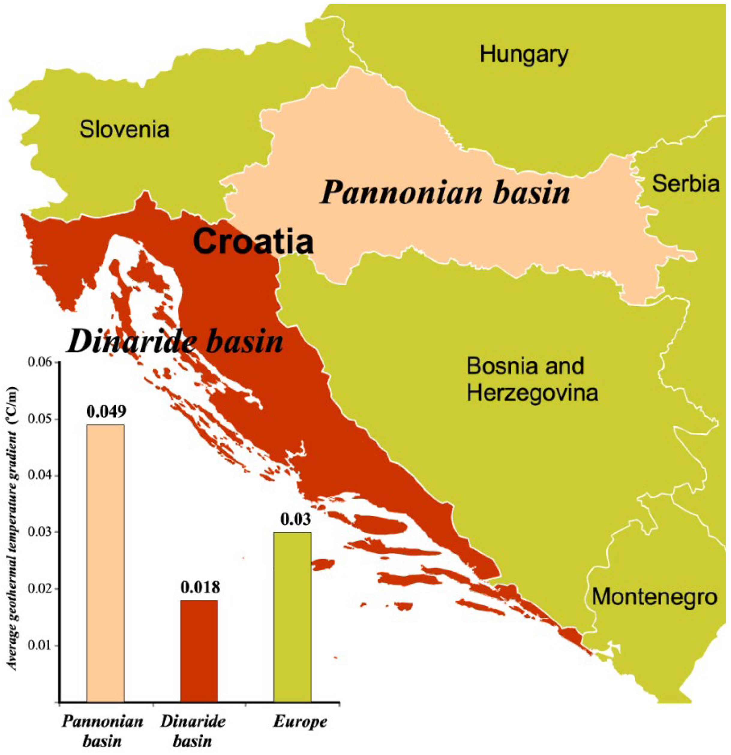
2. Geothermal Potential in Croatia for Electricity Production

The increase in temperature per unit of depth is called the temperature gradient or geothermal gradient, and it is important for the possibility of using geothermal energy. The average value of the geothermal gradient for Europe is 0.03 °C/m, while for Croatia it is from 0.018 °C/m (Adriatic coast and islands, Dinarides) to 0.049 °C/m (Pannonian area), Figure 2. In the “Dinarides” basin, the average heat flux is 29 mW/m2, while in the “Pannonian” basin it is much greater: 76 mW/m2 [5].
Given that the average temperature gradient and heat flux in the Pannonian Basin significantly exceed the European average, it is anticipated that, in addition to the existing geothermal fields, new geothermal fields will be discovered in this region.
Croatia’s geothermal potential consists of approximately 30 geothermal fields (Figure 3), classified into three categories: medium-temperature sources (100–200 °C), low-temperature sources (65–100 °C), and those below 65 °C [5]. Of these, around 20 fields are actively utilized, primarily for space heating and bathing [5]. Only the Velika Ciglena field generates electricity at the Geothermal Power Plant ‘Velika Ciglena’.
In addition to the Velika Ciglena geothermal field, where the aforementioned geothermal power plant is installed, there are several other medium-temperature geothermal sources with temperatures in the range of 100–200 °C (Figure 3), by means of which it is possible to produce electricity: Molve 1 (98 °C), Molve 2 (180 °C), Kalinovac (180 °C), Slatina (183 °C), Lunjkovec-Kutnjak (144 °C), Beničanci (127 °C), Ferdinandovac (125 °C), Babina Greda (121 °C), Rečica-Karlovac (120 °C), Madarinci (117 °C), and Bizovac (113 °C). The electricity generation from these geothermal sources is possible using the binary plants, either with the ORC or with the Kalina cycle.
Binary geothermal power plants with ORC (organic working media in the secondary closed circuit work according to the Rankine cycle) and with the Kalina cycle (the mixture of water and ammonia as working fluid in the secondary circuit, which evaporates in a wide range of temperatures) are described in detail in [1,2].
Previous studies [6,7,8,9,10] conducted an energy-exergy analysis to compare these two cycles for various medium-temperature geothermal resources, including Velika Ciglena, Lunjkovec-Kutnjak, Babina Greda, and Rečica.
Configurations of the proposed binary plants with ORC and Kalina cycle are presented in Figure 4 and Figure 5 and are chosen in such a way that they are very close to the performed, type-designed plants of the leading world manufacturers.
Main components of a binary power plant with an ORC are presented on the power plant scheme in Figure 4a. Heat transfer from geothermal fluid to the organic working fluid is carried out in the preheater and evaporator. Condensate of organic fluid is heated from state 4 to state 5 (to the boiling point) in the preheater while it transforms to dry saturated steam (state 1) in the evaporator. The expansion of steam in the turbine (from state 1 to state 2) provides mechanical work to drive the electric generator. The exhaust steam from the turbine is condensed in an air-cooled condenser by forced convection of air. The feed pump returns condensate to the preheater and evaporator on the initial pressure (from state 3 to state 4). The T-s diagram of ORC is presented in Figure 4b.
Main components of a binary power plant with a Kalina cycle are presented in the power plant scheme in Figure 5a [6]. The working fluid is a mixture of ammonia and water, which has a variable concentration. In the evaporator, the basic mixture with primary concentration (state 1) evaporates by means of geothermal water heat. Generated wet steam (state 2), due to different evaporation temperatures of ammonia and water, consists of a steam portion with increased ammonia concentration and a liquid portion with reduced ammonia concentration. Extracted in the separator steam with increased ammonia concentration (state 1), it expands in the turbine (from state 3 to state 5), performing useful mechanical work to drive the electric generator. The boiling liquid with reduced ammonia concentration (state 4) from the separator flows to the high-temperature preheater, where it preheats the basic ammonia-water mixture condensate. After the high-temperature recuperator, the liquid (state 6) passes through the throttle valve, where its pressure is reduced to the pressure of the turbine exhaust (state 7). Reduced liquid together with exhaust steam is introduced to the mixer, forming wet steam of basic ammonia concentration (state 8). The wet steam first passes through the low-temperature preheater, where a part of its heat has transferred to the condensate from the condenser, so the heat that must be rejected by the air stream during condensation is reduced (state 9 to state 10). The feed pump pumps condensate on the initial pressure value (state 11), and it first passes through the low-temperature preheater, after that through the high-temperature preheater (state 12 to state 1), and finally, it is introduced to the evaporator (state 1). Figure 5b presents a T-s diagram of the Kalina cycle.
Detailed calculations of the plants are provided in [6,7,8,9,10], outlining significant characteristics such as the use of air-cooled condensers in both systems, an average annual air temperature of 15 °C, and the working fluid in the ORC being isopentane, while the Kalina cycle utilizes a water-ammonia mixture that varies in composition during operation. The turbine isentropic efficiencies are 0.85 for the ORC (dry turbine) and 0.75 for the Kalina cycle (wet turbine), with feed pump isentropic efficiencies at 0.8 and pinch point values not falling below 5 °C. These thermodynamic calculations were performed using a binary cycle model based on ORC and Kalina cycles, developed from [1,2,11,12,13,14,15,16,17,18,19]. The thermodynamic properties of the working fluids were determined with the REFPROP® program Version 8.0 [20], while exergy analysis was conducted in accordance with [1,21,22,23,24,25,26,27]. For the exergy balance, the dead state conditions were set at T0 = 298.15 K and p0 = 101,325 Pa.
In the case of all analyzed medium-temperature geothermal resources, the ORC is thermodynamically better than the Kalina cycle, as presented in Table 1. The explanation is given in [6,7,8,9,10]. Thus, for all medium-temperature geothermal sources in Croatia (Velika Ciglena, Lunjkovec, Ferdinandovac, Babina Greda, Rečica, etc.), the application of the binary plants with ORC is proposed.

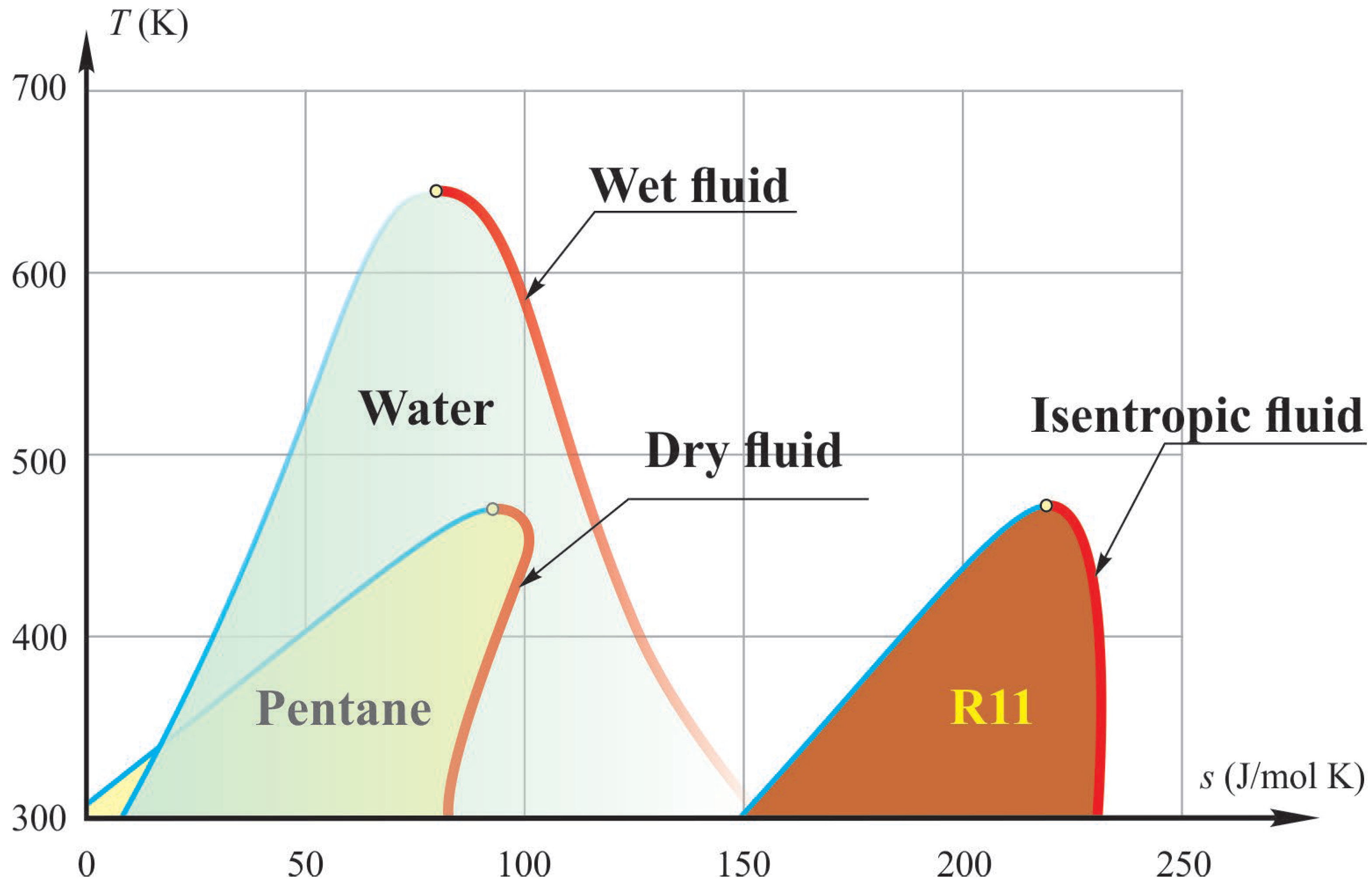
3. Working Fluids for ORC

In ORC, working fluids are pure refrigerants or hydrocarbons [28,29] or their mixtures [29,30]. The organic working fluids are different from water, and depending on the slope of the saturation vapor curve in the T-s diagram, they can be classified as dry, isentropic, or wet fluid, Figure 6 [28]. Wet fluids usually need to be superheated, while dry or isentropic fluids do not need to be superheated.
The effect of various working fluids on ORC characteristics is mainly investigated on low-temperature heat sources such as solar energy [31,32], biomass [33], waste heat [34,35], and ocean energy [36]. This paper deals with the selection of the most suitable fluid(s) for medium-temperature geothermal ORC.
The properties of the working fluid strongly affect the techno-economic characteristics of an ORC, and a bad selection can lead to a low-efficiency and expensive plant. In much research, the characteristics of different working fluids are analyzed, which should be fulfilled for some ORCs. Properties of the working fluid, candidate for ORC, are presented in Table 2 [37,38,39,40].
Table 3 outlines the thermodynamic and physical characteristics of potential working fluids for the ORC utilizing medium-temperature geothermal sources. The molecular mass provides insight into the fluid’s density, and the critical point indicates the applicable temperature and pressure ranges. Environmental considerations are addressed through the ozone depletion potential (ODP), global warming potential (GWP), and atmospheric lifetime (ALT). Furthermore, the ASHRAE refrigerant safety classification assesses the safety level of each fluid [1].
The ideal working fluid, which simultaneously meets all of the requirements, does not exist. The working fluid must be selected from potential candidates on a relative basis.

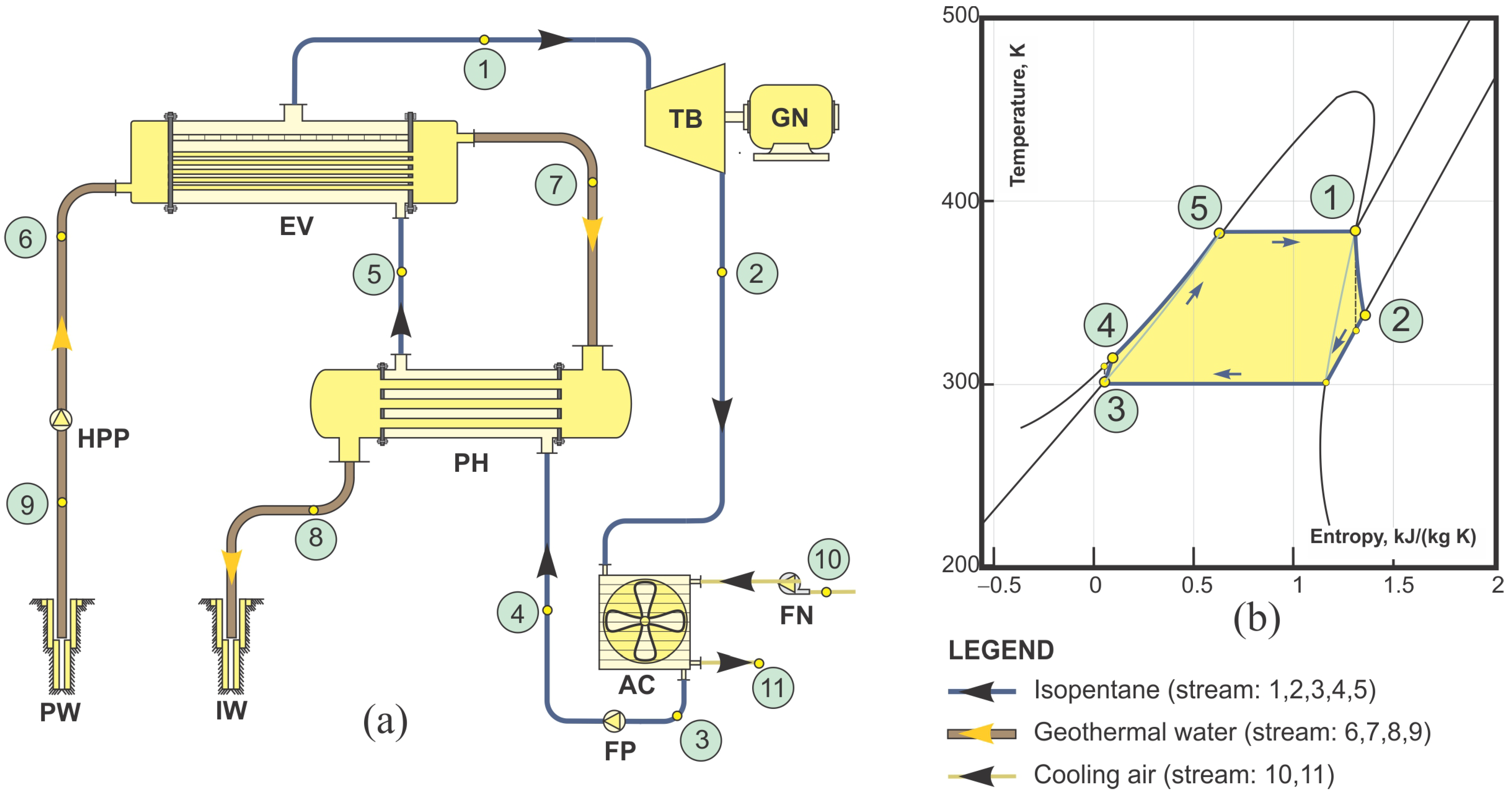
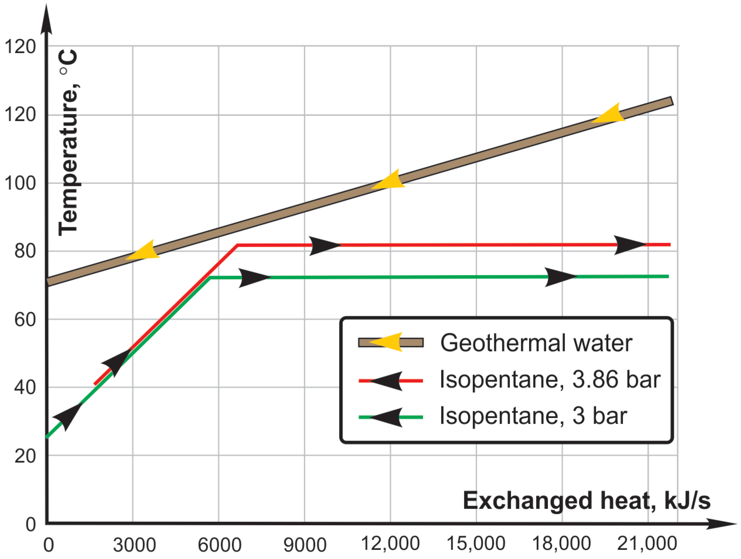
4. Case Study—Geothermal Power Plant “Lunjkovec-Kutnjak”

The geothermal field at Lunjkovec-Kutnjak is located in Koprivnica-Križevci County, within the municipalities of Legrad and Mali Bukovec. This geothermal reservoir is characterized as a closed hydrogeological system with the following features:
  • Resource Classification: It belongs to medium-temperature geothermal resources, which do not have natural replenishment. To maintain the sustainability of the geothermal system, the exhausted geothermal fluid will be reinjected into the reservoir during exploitation.
  • Depth and Thickness: The reservoir is situated at a depth of 2010 m, with an average thickness of 117.5 m.
  • Well Configuration: There are two wells in the system: a production well and an injection well.
  • Production Well Parameters: At the production well, the temperature at the mouth is 140 °C, the pressure is 16 bar, and the flow rate is 70 L per second, achieved using a submerged pump.
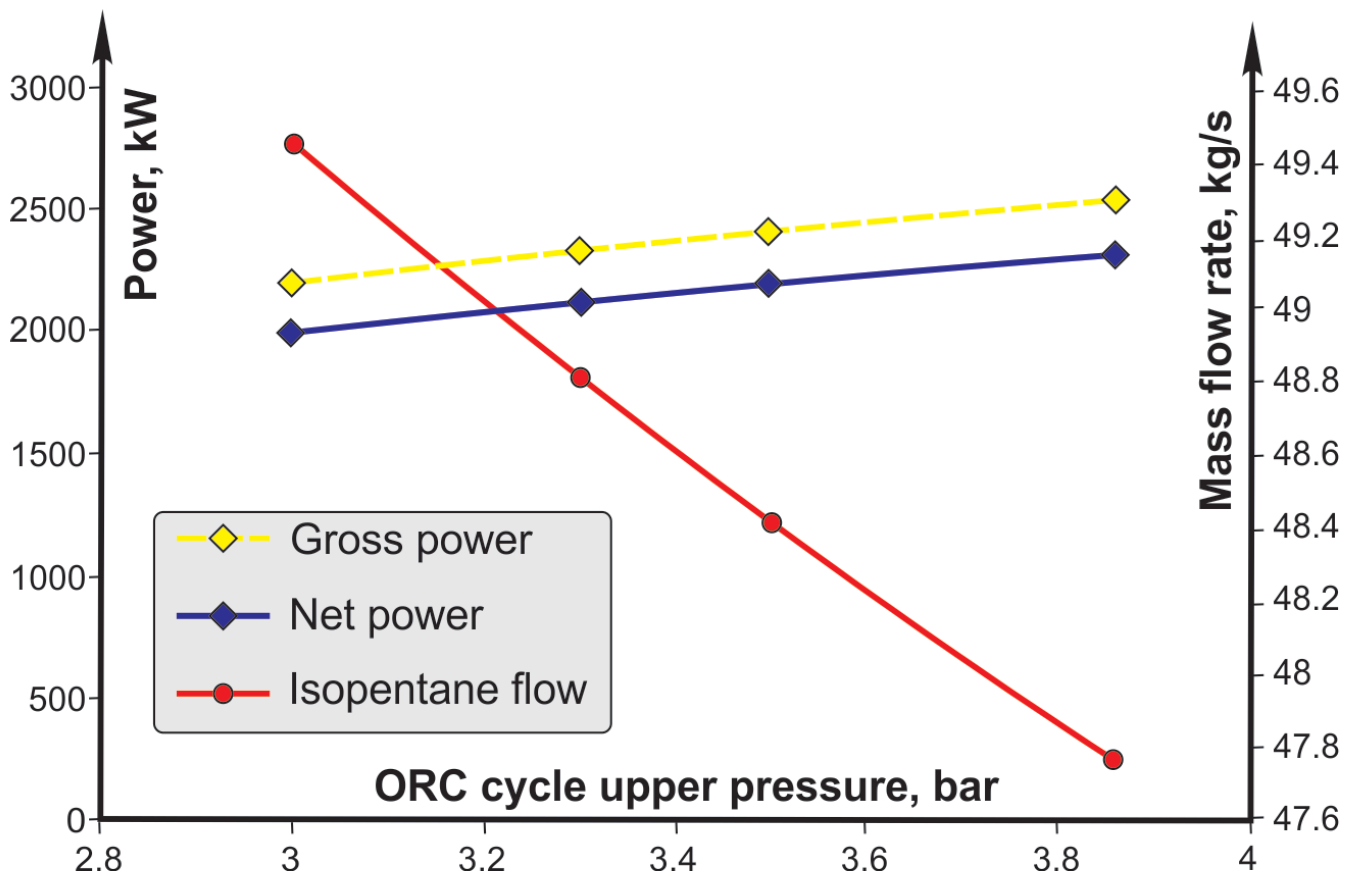
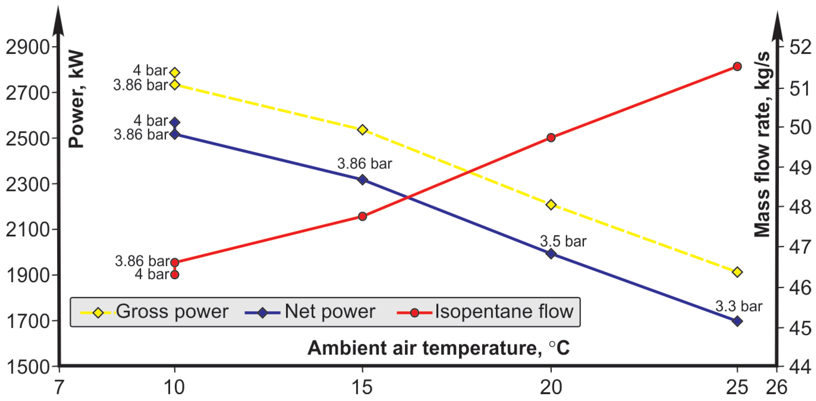
In the proposed ORC plant, geothermal fluid cools from 140 °C to 80 °C, transferring heat to the working fluid. The cooled geothermal water will then be used for direct applications, such as heating buildings, greenhouses, and swimming pools. Economic analyses typically favor combined heat and power (CHP) generation for improved efficiency and profitability [41].
Due to insufficient cooling water for the water-cooled condenser at the Lunjkovec-Kutnjak geothermal field, air-cooled condensers are utilized. Thermodynamic calculations are based on an average annual air temperature of 15 °C, with a pinch point value maintained above 5 °C.
The presumed isentropic efficiencies are as follows: turbine (0.85 for dry turbine), pump (0.80), and fan (0.75).
Calculations for various working fluids (referenced in Table 3) are conducted using a mathematical model of the ORC based on energy and exergy balance equations for the cycle components, presented in Appendix A. Optimization of key cycle parameters, particularly the upper pressure, aims to maximize specific work output, as discussed in [7]. The thermodynamic properties of the working fluids are determined using the REFPROP program [20].
The performance results for the ORC using six working fluids are summarized in Table 4.

5. Discussion

This paper compares six potential working fluids for the ORC utilizing a medium-temperature geothermal source. The comparison focuses on thermodynamic performance metrics, including net power output, mass flow rate, plant efficiency, and the power requirements of the turbine, pump, and fan, as well as rejected heat and cycle pressures. Additionally, the analysis evaluates the physical properties and environmental impacts of each fluid.
Developed a computer program based on the mathematical model of the plant presented in Appendix A (mainly equations of mass and energy balances for each component), allowing a complete overview of the plant operation in different operating conditions for a single working fluid. Optimization of the upper (maximum) pressure of the cycle gives the optimal upper pressure of the cycle, which meets the conditions of the minimum temperature difference in the pinch point (ΔtPINCH,min) between the geothermal water and the working fluid. It gives maximum net power and thus 1st Law efficiency.
If the output temperature of the geothermal fluid in a model is fixed (for secondary consumers), the heat exchanged in the preheater/evaporator will be constant. With a change in the upper pressure of the cycle, the evaporation temperature also changes, and thus the mass flow of the working fluid that can be obtained by exchanging heat. Figure 7. At lower pressure, the evaporation process starts earlier, resulting in a higher mass flow rate of working fluid vapor with the same amount of heat but at the same time a lower temperature.
The final temperature of the geothermal water is fixed; therefore, the heat transferred in the preheater-evaporator is also constant. Furthermore, by increasing the upper pressure of the cycle, the evaporation temperature of the working fluid increases, which causes a decrease in its mass flow (Figure 8).
The obtained steam parameters are significantly higher at higher upper cycle pressures, which is more favorable in terms of net power. It can be seen that a higher net power is obtained with a lower mass flow of the working fluid, but at higher parameters. Also, an increase in the upper pressure of the cycle causes an increase in the required power of the pump and a decrease in the required power of the air condenser fan. The effect of changing the required power of the pump and fan on the net power of the plant is almost constant, i.e., a decrease in the required power of the fan to the same extent causes an increase in the required power of the pump. Due to this fact, the lines of net power and turbine power are parallel.
Another quantity that has a significant impact on the operation of the plant is the environmental temperature (air temperature), as presented in Figure 9 for the case of isopentane as a working fluid. By reducing the environmental temperature, the condensation temperature of the working fluid also decreases, which in all analyzed cases has a favorable effect on the cycle. A decrease in the environmental temperature by 20 °C (summer-winter difference) in the best case causes an increase in net power of almost 27%. An increase in the environmental temperature causes a significant drop in the net power obtained for the same upper cycle pressure. This case can be optimized by reducing the upper pressure of the cycle, which increases the previously obtained net power.
By utilizing the heat accumulated in the geothermal water, i.e., by decreasing the final temperature of the geothermal water in the cycle, the useful power of the plant increases. For example, in the winter mode of operation, with a lower environmental temperature, it will be necessary to increase only the upper pressure of the cycle and leave the final temperature of the geothermal water at a temperature that would meet the level required for the hot water heating system.
In the summer mode of operation, when the environmental temperature is higher and there is no need for hot water heating, it is possible to reduce the final temperature of the geothermal water more than in the winter mode, thus obtaining a higher net power. A decrease in the final temperature of the geothermal water causes a decrease in the upper pressure of the cycle. This case does not have an important impact on the net power, but the task of the plant control is always to achieve the optimal operating mode.
From the previous, it can be seen that the operation of the geothermal plant is affected by a large number of parameters; therefore, for optimal operation, advanced control methods are needed that will enable maximum utilization of the potential at all times.
In the following, the characteristic diagrams for each working fluid will be presented, which, from a technological point of view, show the most favorable working fluid for the ORC described by the previously presented mathematical model (see Appendix A).
The pump power for each working fluid changes depending on the change in the cycle upper pressure. As can be seen from the diagram in Figure 10, the process with isohexane is the least sensitive due to the low upper pressure of the cycle (2.9 bar). Cycles whose optimal operation is at higher pressures will have a steeper characteristic, and the change in pump power for the corresponding change in the cycle’s upper pressure will be significantly higher.
Regarding the change in fan power, the most favorable characteristic is again the cycle with isohexane, which means that, compared to the other presented characteristics, the change in the upper pressure of the cycle will have a significantly smaller effect on the change in fan power (Figure 11).
Figure 12 presents changes in the net power of the plant depending on the change in the cycle upper pressure.
Figure 13, as well as Table 4, presents ORC 1st Law efficiency for the considered working fluids. It can be seen that the cycle with isobutane has the highest efficiency (12.97%), followed by the cycle with R142b (12.94%), R114 (12.76%), R141b (12.72%), isopentane (12.62%), and isohexane (12.56%). Also, Table 4 presents the 2nd Law efficiency. As expected, 2nd Law efficiency is significantly higher than 1st Law efficiency, which is also a consequence of optimizing the upper cycle pressure. The values are as follows: isohexane (37.97%), isobutane (36.40%), R142b (36.30%), R114 (35.78%), R141b (35.69%), and isopentane (35.41%). The values are in a narrow range of change, and the order for different working fluids is slightly different than for 1st Law efficiency.
The results presented in Table 3 and Figure 13 show that the geothermal power plant utilizing ORC with six selected working fluids (properties listed in Table 2) achieves an efficiency ranging from 12.56% to 12.97%. The net power output varies between 2093.71 kW and 2227.46 kW, with mass flow rates from 35.13 kg/s to 97.08 kg/s.
The power ranges for the turbine, pump, and fan are as follows:
  • Turbine: 2068.12 kW to 2449.44 kW
  • Pump: 17.72 kW to 173.29 kW
  • Fan: 140.95 kW to 141.61 kW
Key cycle parameters include upper and lower pressures, which range from 2.9 bar to 23.0 bar and from 0.3 bar to 3.5 bar, respectively. The heat rejected from the working fluid to the cooling fluid (air) varies in accordance with changes in plant efficiency.
When selecting the most suitable working fluid from Table 2, several key factors should be additionally considered. The turbine size factor [42,43] and evaporator pressure (upper cycle pressure) [42] are crucial. It is preferable for the working fluid to have high latent heat, high density, and low liquid-specific heat [44,45]. Additionally, the design condensation temperature should typically be above 300 K, along with careful consideration of the critical temperature [42] and the fluid’s freezing point. An acceptable pressure range is also essential [46]. Finally, the working fluid must exhibit chemical stability, be non-corrosive, and be compatible with engine materials [47,48].
The Ozone Depletion Potential (ODP) and Global Warming Potential (GWP) indicate a substance’s potential to contribute to ozone degradation and global warming. According to the ASHRAE refrigerant safety classification, the selected working fluids should ideally be non-flammable and non-toxic. Additionally, the availability and cost of the working fluids are critical factors in the selection process.

6. Conclusions

This paper examines the potential of six distinct working fluids for generating electricity through an Organic Rankine Cycle (ORC) utilizing a medium-temperature geothermal source, with a case study of the Geothermal Power Plant “Lunjkovec-Kutnjak”. The ORCs employing the selected working fluids demonstrate a plant 1st Law efficiency between 12.56% and 12.97%, resulting in net power outputs ranging from 2093.71 kW to 2227.46 kW. Second Law efficiency is significantly higher than 1st Law efficiency, and it changes in the very narrow range of 37.97% to 35.41%. In this respect, all working fluids are equally favorable. Also, all working fluids are satisfactory with regard to evaporator pressure (upper cycle pressure), latent heat, density, specific heat, design condensation pressure (temperature), specific volume at the turbine exit (the turbine size factor), the critical temperature, the freezing point, pressure range, chemical stability, non-corrosiveness, and compatibility with engine materials (Table 2). So it is necessary to set additional criteria such as environmental impact.
After that, the following fluids are not recommended:
  • R114, R142b, and R141b have high ALT (Atmospheric Lifetime), GWP (Global Warming Potential), and ODP (Ozone Depletion Potential);
  • Although the working fluids, such as isohexane and isobutane (R600a), are the fluids with the highest plant efficiency and plant net power, they have a high upper pressure or low lower pressure.
In conclusion, working fluid R601a (isopentane) (low ALT, ODP, and GWP; favorable upper and lower pressure, etc.) is the most suitable fluid for ORC with a medium-temperature geothermal source. The final confirmation should be given by the techno-economic analysis (the complexity and cost of the plant).

Author Contributions

Conceptualization, Z.G. and Z.B.M.; methodology, Z.G. and Z.B.M.; investigation, Z.G., Z.B.M. and M.B.; data curation, Z.G. and Z.B.M.; writing—original draft preparation, Z.G., Z.B.M. and M.B.; writing—review and editing, Z.G., Z.B.M. and M.B.; supervision, Z.G.; project administration, Z.G. All authors have read and agreed to the published version of the manuscript.

Funding

This research received no external funding.

Data Availability Statement

The original contributions presented in the study are included in the article, further inquiries can be directed to the corresponding author.

Conflicts of Interest

The authors declare no conflicts of interest.

Appendix A. Mathematical Model of ORC: Equations of Mass and Energy Balances

Thermodynamic modeling is necessary for the calculation of all parameters in a power plant, and it is used to analyze thermodynamic behavior. The design of a new power plant starts with making his mathematical model. Thermodynamics of the conversion processes in single components of the binary plants with ORC are given in [1,2,11,12,13,14,15,16,17,18,19].
This mathematical model of the power plant with an ORC is created in the Microsoft Office Excel® program tool with the application of the National Institute of Standards and Technology REFPROP® program Version 8.0 [20], which enables the determination of the necessary plant state parameters. The REFPROP® program Version 8.0 can be integrated into Microsoft Office Excel®, which ensures additional functionality of the created calculation and enables automatic optimization of the calculation according to the given parameters. The mentioned program contains the functions necessary to calculate the state parameters of hot liquid, dry saturated steam, and superheated steam for a large number of commercial fluids and their mixtures used in various processes.
The mathematical model consists of a system of linear equations of mass and energy balances in order to describe certain characteristic points in the cycle with appropriate parameters. The plant contains three fluid circuits in the cycle (geothermal water, working fluid, and cooling fluid (air)), so it is useful to set up equations for each fluid. Each equation will be followed by the corresponding REFPROP® program Version 8.0 function used for the calculation. The functions in the REFPROP® program Version 8.0 are defined as follows:
=Requested Property (fluid; known properties; system of measurement units; sv1; sv2)
The required property represents the characteristic of the fluid that is calculated using the REFPROP® program Version 8.0; for example, Density is entered for density, Enthalpy for enthalpy, Entropy for entropy, and so on for all other quantities that can be calculated with the REFPROP® program Version 8.0. The fluid is specified in such a way that the name of the fluid is entered in the formula with a previous check on the reference list of fluids for which it is possible to calculate the properties.
Known properties are given in such a way that, for example, for known temperature and pressure, TP is written into the formula, where T stands for temperature and P for pressure. Other abbreviations of known properties are presented in the instructions for using the REFPROP® program Version 8.0. The system of measurement units is specified because the REFPROP® program Version 8.0 can calculate in several systems of measurement units, for example, in the SI system, the SI system with °C instead of Kelvin, the English system, etc. It is specified in such a way as to write SI or SI with C (only C). It is necessary to pay attention that the pressure is given in MPa. Sv1 and sv2 represent the values of the known properties that were previously listed. The values of the properties must be entered in the order in which they were previously defined; for example, if TP is specified, it is necessary to enter the temperature value in sv1 and the pressure value in sv2.
The input plant parameters for the mathematical model are presented in Table A1.
Table A1. The input plant parameters.
ParameterValue
Volume flow rate of geothermal water, V ˙ g w 70.00 L/s
Initial temperature of geothermal water, t 1 g w 140.00 °C
Pressure of geothermal water, p g w 16.00 bar
Final temperature of geothermal water, t 2 g w 80.00 °C
Environmental temperature (of cooling air), t 1 c f 15.00 °C
Air temperature increase, t c f 5.00 °C
Minimum temperature difference in pinch point, ΔtPINCH,min 5.00 °C
Air condenser characteristics, Δ t c o n d , m i n 5.00 °C
Environmental pressure, p c f 1.00 bar
Air velocity increase, c c f 10.00 m/s
Pump efficiency, η P 0.80
Turbine efficiency, η T 0.85
Pressure drops occurred in various components, and pipes are not considered. Figure A1 shows the working fluid states at different points and processes of energy conversion in an ORC. Denotations in the next equations correspond to those in Figure A1.
The equations that make the mathematical model are summarized below.
The initial and final enthalpy of the geofluid, as well as the density of the geofluid, h 1 g w ,   h 2 g w , ρ g w :
h 1 g w = f ( t 1 g w ,   p g w ) = Enthalpy ( water ;   T P ;   C ; t 1 gw ;   p gw )
ρ g w = f t 1 g w ;   p g w = Density ( water ;   T P ;   C ;   t 1 gw ;   p gw )
h 2 g w = f ( t 2 g w ,   p g w ) = Enthalpy ( water ;   T P ;   C ;   t 2 gw ;   p gw )
The final temperature and initial and final enthalpy of the cooling fluid (of air), t 2 c f ,   h 1 c f , h 2 c f :
t 2 c f = t 1 c f + Δ t c f
h 1 c f = f ( t 1 c f ,   p c f ) = Enthalpy ( air ;   T P ;   C ;   t 1 cf ;   p cf )
h 2 c f = f ( t 2 c f ,   p c f ) = Enthalpy ( air ;   T P ;   C ;   t 2 cf ;   p cf )
Figure A1. T-s diagram of the ORC with characteristic points (black—ideal cycle; red—actual cycle).
Energies 18 01699 g0a1
Based on the environmental temperature at the location t1cf, the increase in air temperature during heat exchange Δtcf, and the minimum temperature difference in the condenser Δtcond,min, the temperature, pressure, and enthalpy of the working fluid at the outlet of the condenser (Figure A1, point 3/4is/4), t 3 w f , p 3 w f , h 3 w f :
t 3 w f = t 1 c f + Δ t c f + Δ t c o n d , m i n
p 3 w f = f ( t 3 w f ) = Enthalpy ( WF ;   T liq ;   C ;   t 3 wf )
h 3 w f = f ( t 3 w f ,   p 3 w f ) = Enthalpy ( WF ;   T P ;   C ;   t 3 RM ;   p 3 RM )
The entropy of the working fluid at the outlet of the condenser (Figure A1, point 3/4is/4), s 4 i s :
s 4 i s = s 3 w f = f ( t 3 w f ,   p 3 w f ) = Entropy ( WF ;   T P ;   C ;   t 3 wf ;   p 3 wf )
From the stated entropy and the upper pressure of the cycle p1 = p4wf, which is assumed and optimized depending on the properties of the working fluid, the state after isentropic compression, and then after adiabatic (real) compression in the pump, h 4 i s , w f , h 4 w f :
h 4 i s , w f = f ( s 4 i s = s 3 w f ,   p 1 = p 4 w f ) = Enthalpy ( WF ;   P S ;   C ;   p 4 wf ;   s 4 wf )
h 4 w f = h 3 w f + h 4 i s h 3 w f η P
The properties of the working fluid at the inlet and outlet of the preheater-evaporator (Figure A1, point 5, point 1), h 5 w f ,   t 5 w f , h 1 w f , t 1 w f , s 1 w f :
h 5 w f = f ( p 1 = p 4 w f ) = Enthalpy ( WF ;   P liq ;   C ;   p 4 wf )
t 5 w f = t 1 w f
h 1 w f = f ( p 1 = p 4 w f ) = Enthalpy ( WF ;   P vap ;   C ;   p 4 wf )
t 1 w f = f ( p 1 = p 4 w f ) = Temperature ( WF ;   P vap ;   C ;   p 4 wf )
s 1 w f = f ( p 1 = p 4 w f ) = Entropy ( WF ;   P vap ;   C ;   p 4 wf )
The pressure of the working fluid at the exit from the turbine (Figure A1, point 2) is equal to the pressure in the condenser, p 2 i s :
p 2 i s = p 2 w f = p 3
The enthalpy of working fluid after the real (adiabatic) expansion in the turbine, s 2 i s , h 2 i s ,   h 2 w f :
s 2 i s = s 1 w f
h 2 i s = f ( p 2 i s = p 2 w f = p 3 , s 2 i s = s 1 w f ) = Enthalpy ( WF ;   P S ;   C ;   p 2 wf ;   s 2 is )
h 2 w f = h 1 w f + h 2 i s , w f h 1 w f η T
These equations determine the states of all fluids in all cycle characteristics points needed for further calculation.
The mass flow rate of the geofluid, m ˙ g f :
m ˙ g f = V ˙ g f × ρ g f
The supplied heat from geothermal fluid to working fluid in cycle, Q g f :
Q g f = m ˙ g f h 1 g f h 2 g f
The working fluid mass flow rate, m ˙ w f :
m ˙ w f = Q g f h 1 w f h 4 w f
The heat transfered from the geothermal fluid to the working fluid in pre-heater (PH), Q P H :
Q P H = m ˙ w f h 5 w f h 4 w f
The enthalpy and temperature of the geothermal water at the pinch point, h g f , P I N C H , t g f , P I N C H :
h g f , P I N C H = h 2 g f + Q P R E m ˙ g f
t g f , P I N C H = f ( p g f , h g f ,   P I N C H ) = Temperature ( WF ;   P H ;   C ;   p gf ;   h gf , PINCH )
The power of the turbine, P T :
P T = m ˙ w f h 1 w f h 2 w f
The heat rejected from the working fluid to the cooling fluid (air) in the condenser, Q c o n d :
Q c o n d = m ˙ w f h 2 w f h 3 w f
The mass flow rate of cooling fluid (air), m ˙ c f :
m ˙ c f = Q c o n d h 2 c f h 1 c f
The power of the fan (transferred to the cooling fluid), P F :
P F = m ˙ c f c c f 2 2
The power of the feed pump (transferred to the working fluid), P P :
P P = m ˙ w f h 4 w f h 3 w f
Plant net power, P n e t :
P n e t = P T P P P F
The plant efficiency (the First Law efficiency), η 1 s t L a w   :
η 1 s t L a w   = P n e t Q g f
The plant Second Law efficiency, η 2 n d L a w   :
η 2 n d L a w   = P n e t m ˙ g f h r e s h 0 T 0 s r e s s 0

References

  1. Di Pippo, R. Geothermal Power Plants—Principles, Applications and Case Studies; Elsevier Ltd.: Oxford, UK, 2005. [Google Scholar]
  2. Gupta, H.; Roy, S. Geothermal Energy: An Alternative Resource for the 21st Century; Elsevier, B.V.: Amsterdam, The Netherlands, 2007. [Google Scholar]
  3. Available online: https://www.thinkgeoenergy.com (accessed on 25 March 2024).
  4. Lund, J.W.; Toth, A.N. Direct Utilization of Geothermal Energy 2020 Worldwide Review. In Proceedings of the World Geothermal Congress 2020, Reykjavik, Iceland, 24–27 October 2021. [Google Scholar]
  5. Bošnjak, R.; Čubrić, S.; Golub, M.; Grabovski, K.; Jelić, K.; Kolin, I.; Košćak, S.; Kulenović, I.; Mioćev, D.; Pravica, Z.; et al. A Program of Geothermal Energy Usage in the Republic of Croatia; Energy Institute “Hrvoje Požar”: Zagreb, Croatia, 1998. [Google Scholar]
  6. Guzović, Z.; Lončar, D.; Ferdelji, N. Possibilities of electricity generation in the Republic Croatia by means of geothermal energy. Energy 2010, 35, 3429–3440. [Google Scholar]
  7. Guzović, Z.; Majcen, B.; Cvetković, S. Possibilities of electricity generation in the Republic Croatia from medium temperature geothermal sources. Appl. Energy 2012, 98, 404–414. [Google Scholar] [CrossRef]
  8. Rašković, P.; Guzović, Z.; Cvetković, S. Performance analysis of electricity generation by the medium temperature geothermal resources: Velika Ciglena case study. Energy 2013, 54, 11–31. [Google Scholar] [CrossRef]
  9. Guzović, Z.; Martan, B.; Majcen, B. Possibilities of electricity generation in The Republic Croatia by means of low temperature geothermal sources. In Proceedings of the 21st International Symposium on Heating, Refrigerating and Air Conditioning, Zagreb, Croatia, 26–28 October 2011. [Google Scholar]
  10. Šoški, J. Steam Turbine for Geothermal Power Plant Rečica. Diploma Thesis, University of Zagreb, Faculty of Mechanical Engineering and Naval Architecture, Zagreb, Croatia, 2011. [Google Scholar]
  11. Davis, A.P.; Michaelides, E.E. Geothermal power production from abandoned oil wells. Energy 2009, 34, 866–872. [Google Scholar] [CrossRef]
  12. Gallup, D.L. Production engineering in geothermal technology: A review. Geothermics 2009, 38, 326–334. [Google Scholar]
  13. Clauser, C. Geothermal Energy; Group VIII—Advanced Materials and Technologies, Vol. 3: Energy Technologies, Subvol. C: Renewable Energies; Springer: Heidelberg/Berlin, Germany, 2006; pp. 493–604. [Google Scholar]
  14. Hettiarachchi, H.D.M.; Golubovic, M.; Worker, W.M.; Ikegami, Y. Optimum design criteria for an Organic Rankine cycle using low-temperature geothermal heat sources. Energy 2007, 32, 1698–1706. [Google Scholar]
  15. Rašković, P.; Stoiljković, S. Pinch design method in the case of a limited number of process streams. Energy 2009, 34, 593–612. [Google Scholar]
  16. Mlcak, H.A. An Introduction to the Kalina Cycle. In Proceedings of the International Joint Power Generation Conference, Houston, TX, USA, 13–17 October 1996. PWR-Vol. 30. [Google Scholar]
  17. Mlcak, H.A. Kalina cycle® concepts for low temperature geothermal. Geotherm. Resour. Counc. Trans. 2002, 26, 703–713. [Google Scholar]
  18. Valdimarsson, P. Geothermal power plant cycles and main components. In Proceedings of the Short Course on Geothermal Drilling, Resource Development and Power Plants, Santa Tecla, El Salvador, 16–22 January 2011; pp. 1–24. [Google Scholar]
  19. Ibrahim, O.M. Design considerations for ammonia-water Rankine cycle. Energy 1996, 21, 835–841. [Google Scholar]
  20. Lemmon, E.W.; Huber, M.L.; McLinden, M.O. Reference Fluid Thermodynamic and Transport Properties—REFPROP; NIST Standard, Reference Detabase 23, Version 8.0; Physical and Chemical Properties Division, U.S. Secretary of Commerce on Behalf of The United States of America: Washington, DC, USA, 2008. [Google Scholar]
  21. Di Pippo, R. Second Law assessment of binary plants generating power from low-temperature geothermal fluids. Int. J. Geotherm. 2004, 33, 565–586. [Google Scholar] [CrossRef]
  22. Tsatsaronis, G.; Cziesla, F. Thermoeconomics. In Encyclopedia of Physical Science and Technology; Elsevier: London, UK, 2002. [Google Scholar]
  23. Morosuk, T.; Tsatsaronis, G. New approach to the exergy analysis of absorption refrigeration machines. Energy 2008, 33, 890–907. [Google Scholar] [CrossRef]
  24. Bloomster, C.H.; Fassbender, L.L. The role of second law analysis in geothermal economics. Energy 1980, 5, 839–851. [Google Scholar] [CrossRef]
  25. Yari, M. Exergetic analysis of various types of geothermal power plants. Renew. Energy 2010, 35, 112–121. [Google Scholar] [CrossRef]
  26. Frick, S.; Kaltschmitt, M.; Schröder, G. Life cycle assessment of geothermal binary power plants using enhanced low-temperature reservoirs. Energy 2010, 35, 2281–2294. [Google Scholar] [CrossRef]
  27. Rašković, P.; Cvetković, S.; Stoiljković, S. Exergy analyse of CHP plant TE-TO Zrenjanin. In Proceedings of the 3rd Dubrovnik Conference on SDEWES, Dubrovnik, Croatia, 5–10 June 2005; pp. 518–530. [Google Scholar]
  28. Saleh, B.; Koglbauer, G.; Wendland, M.; Fischer, J. Working fluids for low-temperature organic Rankine cycles. Energy 2007, 32, 1210–1221. [Google Scholar] [CrossRef]
  29. Aghahosseini, S.; Dincer, I. Comparative performance analysis of low-temperature Organic Rankine Cycle (ORC) using pure and zeotropic working fluids. Appl. Therm. Eng. 2013, 54, 35–42. [Google Scholar] [CrossRef]
  30. Gianfranco, A.; Colonna di Paliano, P. Multicomponent Working Fluids for ORCs. Energy 1998, 23, 449–463. [Google Scholar]
  31. Tchanche, B.F.; Papadakis, G.; Lambrinos, G.; Frangoudakis, A. Fluid selection for a low-temperature solar organic Rankine cycle. Appl. Therm. Eng. 2009, 29, 2468–2476. [Google Scholar] [CrossRef]
  32. Delgado-Torres, A.M.; Garcia-Rodriguez, L. Analysis and optimization of the low-temperature solar organic Rankine cycle (ORC). Energy Convers. Manag. 2010, 51, 2846–2856. [Google Scholar] [CrossRef]
  33. Drescher, U.; Bruggemann, D. Fluid selection for the organic Rankine cycle (ORC) in biomass power and heat plants. Appl. Therm. Eng. 2007, 27, 223–228. [Google Scholar] [CrossRef]
  34. Liu, B.T.; Chien, K.H.; Wang, C.C. Effect of working fluids on organic Rankine cyclefor waste heat recovery. Energy 2004, 29, 1207–1217. [Google Scholar] [CrossRef]
  35. Borsukiewicz-Gozdur, A.; Nowak, W. Comparative analysis of natural and synthetic refrigerants in application to low temperature Clausisu-Rankine cycle. Energy 2007, 32, 344–352. [Google Scholar] [CrossRef]
  36. Hung, T.C.; Wang, S.K.; Kuo, C.H.; Pei, B.S.; Tsai, K.F. A study of organic working fluids on system efficiency of an ORC using low-grade energy sources. Energy 2010, 35, 1403–1411. [Google Scholar] [CrossRef]
  37. Chen, H.; Goswami, D.Y.; Stefanakos, E.K. A review of thermodynamic cycles and working fluids for the conversion of low-grade heat. Renew. Sustain. Energy Rev. 2010, 14, 3059–3067. [Google Scholar]
  38. Gawlik, K.; Hassaqni, V. Advanced Binary Cycles: Optimum working Fluids. In Proceedings of the Geothermal Resources Council 1998: Annual Meeting, San Diego, CA, USA, 20–23 September 1998. [Google Scholar]
  39. West, H.H.; Patton, J.M.; Starling, K.E. Selection of Working Fluids for The Organic Rankine Cycle. In Proceedings of the 1st Industrial Energy Technology Conference, Houston, TX, USA, 21–22 April 1979. [Google Scholar]
  40. Zhu, Q.; Sun, Z.; Zhou, J. Performance Analysis of Organic Rankine Cycles Using Different working Fluids. Therm. Sci. 2015, 19, 179–191. [Google Scholar]
  41. Kanoglu, M.; Cengel, Y.A. Economic evaluation of geothermal power generation, heating, and cooling. Energy 1999, 24, 501–509. [Google Scholar]
  42. Lakew, A.A.; Bolland, O. Working fluids for low-temperature heat source. Appl. Therm. Eng. 2010, 30, 1262–1268. [Google Scholar] [CrossRef]
  43. Invernizzi, C.; Iora, P.; Silva, P. Bottoming micro-Rankine cycles for micro-gas turbines. Appl. Therm. Eng. 2007, 27, 100–110. [Google Scholar] [CrossRef]
  44. Maizza, V.; Maizza, A. Unconvential working fluids in organic Rankine-cycles for waste energy recovery systems. Appl. Therm. Eng. 2001, 21, 381–390. [Google Scholar]
  45. Yamamoto, T.; Furuhata, T.; Arai, N.; Mori, K. Design and testing of the ORC. Energy 2001, 26, 239–251. [Google Scholar]
  46. Quoilin, S. Experimental Study and Modeling of a Low Temperature Rankine Cycle for Small Scale Cogeneration. Ph.D. Thesis, University of Liege, Liège, Belgium, 2007. [Google Scholar]
  47. Calderazzi, L.; di Paliano, P.C. Thermal stability of R-134, R-141b, R-1311, R-7146, R-125 associated with stainless steel as a containing material. Int. J. Refrig. 1997, 20, 381–389. [Google Scholar]
  48. Bao, J.; Zhao, L. A review of working fluid and expander selections for organic Rankine cycle. Renew. Sustain. Energy Rev. 2013, 24, 325–342. [Google Scholar] [CrossRef]
Figure 1. Geothermal power plant “Velika 1” at Velika Ciglena—Croatia (photo by author).
Energies 18 01699 g001
Figure 2. Geothermal gradients in the Republic of Croatia [5].
Energies 18 01699 g002
Figure 3. Geothermal potentials in the Republic of Croatia [5].
Energies 18 01699 g003
Figure 4. Binary plant with the ORC: (a) scheme of a plant (HPP-high pressure pump, FP-feed pump, PH-preheater, EV-evaporator, AC-air condenser, TB-turbine, GN-generator, PW production well, IW-injection well) and (b) temperature–entropy diagram [6].
Energies 18 01699 g004
Figure 5. Binary plant with the Kalina cycle: (a) scheme of a plant (HPP—high-pressure pump, FP—feed pump, LTR—low-temperature preheater, HTR—high-temperature preheater, EV—evaporator, SP—separator, MX—mixer, TR—throttle valve, AC—air condenser, TB—turbine, GN—generator, PW—production well, IW—injection well) and (b) temperature–enthalpy diagram of the binary cycle with the Kalina cycle [6].
Energies 18 01699 g005
Figure 6. Types of working fluids used in ORC: dry, isentropic, and wet [28].
Energies 18 01699 g006
Figure 7. Optimization of the upper cycle pressure (of evaporation)—the case of isopentane as a working fluid.
Energies 18 01699 g007
Figure 8. Influence of upper pressure (evaporation) on the mass flow of the working fluid—the case of isopentane as a working fluid.
Energies 18 01699 g008
Figure 9. Influence of ambient air temperature on the mass flow of the working fluid and net (gross) power—the case of isopentane as a working fluid.
Energies 18 01699 g009
Figure 10. The changes in pump power depend on the changes in the cycle upper pressure for the considered working fluids.
Energies 18 01699 g010
Figure 11. The changes in fan power depend on the changes in the cycle upper pressure for the considered working fluids.
Energies 18 01699 g011
Figure 12. The changes in the plant’s net power depend on the changes in the cycle’s upper pressure for the considered working fluids.
Energies 18 01699 g012
Figure 13. Frist Law efficiency for a particular working fluid at the optimal upper pressure.
Energies 18 01699 g013
Table 1. The comparison of geothermal power plants with ORC and Kalina cycle in cases of medium-temperature geothermal fields in Croatia [6,7,8,9,10].
Geothermal FieldGeothermal FluidOrganic Rankine Cycle (ORC)Kalina Cycle
Flow Rate
[kg/s]
Input
Temp.
[°C]
Output
Temp.
[°C]
Cycle Net
Power
[kW]
1st Law Effici.
[%]
2nd Law Effici.
[%]
Cycle Net
Power
[kW]
1st Law Effici. [%]2nd Law Effici.
[%]
Velika
Ciglena
83.017069527014.152394910.644
Lunjkovec-
Kutnjak
64.87140802225.513.546.22101.412.843
Babina
Greda
93.97125702509.911.546.32317.410.742.7
Rečica94.38120801964.112.435.91872.411.834.2
Table 2. Properties of the ideal working fluid for ORC [37,38,39,40].
PropertiesReason
1.As low as possible dew point pressure at the point of initial condensation but greater than atmospheric pressure:
-
to minimize condenser cost per unit of heat transfer surface area;
-
to avoid leakage of air into the system
2.Nearly vertical saturated vapor line in a T-s diagram:
-
to avoid excessive superheat in heat exchangers (small heat transfer coefficient);
-
to avoid condensation in the turbine (loss due to condensation and blade erosion)
3.Large specific enthalpy drop in the turbine:
-
to maximize cycle thermodynamic efficiency;
-
to minimize working fluid flow rate;
-
if specific enthalpy drop becomes too large, less efficient and more costly multi-stage turbines (optimal drop exists)
4.Reasonably low turbine inlet pressure:
-
to minimize heat exchanger cost per unit of heat transfer surface area
5.A small heat of evaporation and a matching heat resource:
-
to maximize energy utilization
6.A low specific heat:
-
to avoid a high load for condenser
7.Small specific volume at the turbine exit (turbine size factor):
-
to keep small turbine size
8.Large thermal conductivity coefficients:
-
to minimize heat transfer surface area due to higher convective heat transfer coefficients
9.Low viscosities:
-
to minimize frictional pressure drops;
-
maximize convective heat transfer coefficients
10.Appropriate freezing point:
-
below the lowest operating temperature in the cycle
11.Sufficiently high boiling temperature under atmospheric pressure:
-
to avoid more stringent requirements for the selection of the condenser.
12.Chemical stable under working conditions:
-
to avoid decomposition, resulting in material corrosion and possible detonation
13.Low both ODP and GWP:
-
due to environmental protection
14.A high flash point:
-
to avoid flammability
15.A low toxicity:
-
due to the personnel protection from contamination in case of a fluid leakage
16.Low cost, essentially non-fouling, non-corrosive
-
due to low plant cost and its maintenance
Table 3. Properties of the working fluids considered in the paper [31,32].
Working FluidPhysical DataSafety Data-
ASHRAE 34 Safety Group
Environmental Data
Molecular Mass, M [kg/kmol]Boiling Point,
Tbp [°C]
Critical PointALT
[yr]
ODP
[-]
GWP
[100 yr]
Tcrit
[°C]
pcrit [MPa]
hexane86.1868.71234.673.034n.a.n.a.n.a.n.a.
R114170.923.6145.73.257A1300110,000
R142b100.5−9.12137.114.06A217.90.072310
R141b116.9532.05204.354.212A29.30.12725
R600a58.12−11.7134.73.63A312 ± 304
R601a72.127.8187.23.78A312 ± 304 ± 2
Table 4. The calculation results (performances) of ORCs for selected working fluids from Table 3 (Temperature of geothermal water, t 1 g w = 140.00 °C; Condensation temperature, t 3 w f = 25.00 °C).
Working FluidPerformances of ORC
Type of Working FluidCycle Net Power,
P n e t
[kW]
Mass Flow of Working Fluid,
m ˙ w f
[kg/s]
1st Law
(2nd Law)
Efficien.,
η 1 s t L a w
( η 2 n d L a w )
[%]
Turbine   Power ,   P T
[kW]
Pump   Power ,   P P
[kW]
Fan   Power ,   P F
[kW]
Heat Rejected,
Q c o n d
[kW]
Upper Pressure,
p m a x
[bar]
Lower Pressure,
p m i n
[bar]
hexanedry2227.4635.1312.56
(37.97)
2068.1217.72141.6114,250.482.90.3
R114dry2099.5597.0812.76
(35.79)
2354.61113.75141.3014,219.3615.82.1
R142bisentropic2129.3768.6412.94
(36.30)
2413.88143.51141.0114,189.8322.03.4
R141bisentropic2093.7160.6412.72
(35.69)
2265.8730.80141.3614,225.145.80.8
R600a-
isobutane
dry2135.2139.2612.97
(36.40)
2449.44173.29140.9514,184.0523.03.5
R601a-
isopentane
dry2077.3235.8912.62
(35.41)
2263.1944.34141.5214,241.377.00.9
Disclaimer/Publisher’s Note: The statements, opinions and data contained in all publications are solely those of the individual author(s) and contributor(s) and not of MDPI and/or the editor(s). MDPI and/or the editor(s) disclaim responsibility for any injury to people or property resulting from any ideas, methods, instructions or products referred to in the content.

