
Research on Energy Management Strategy Based on Adaptive Equivalent Fuel Consumption Minimum for Hydrogen Hybrid Energy Systems

Abstract
1. Introduction
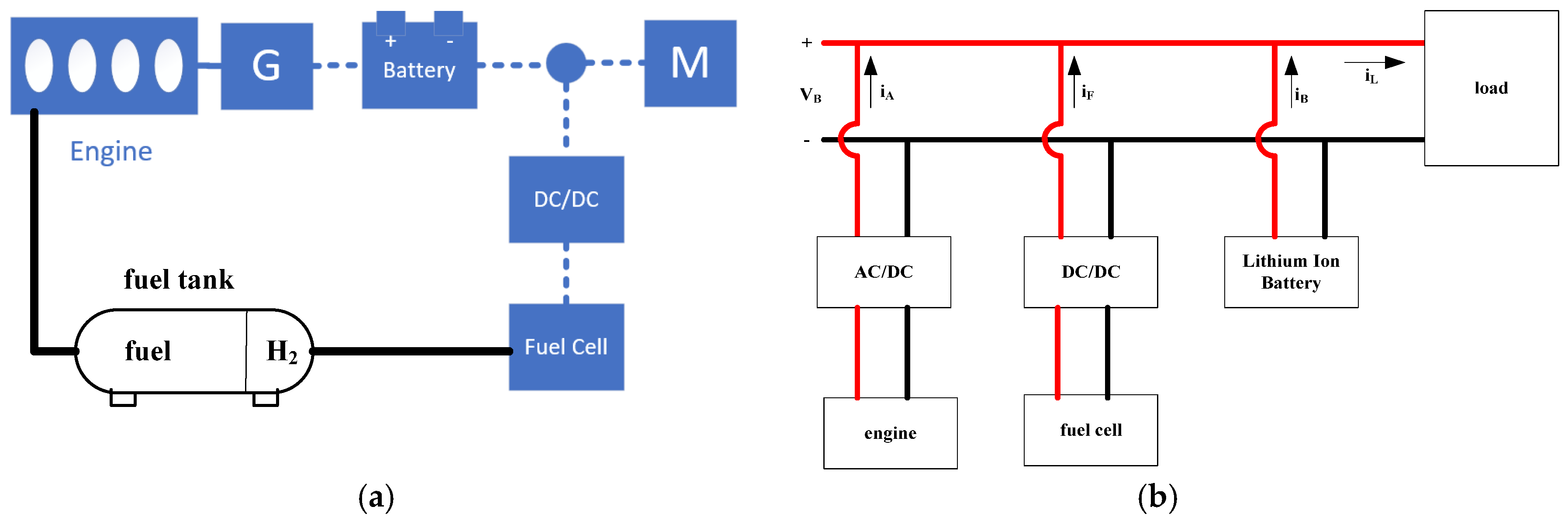
2. Model of Hydrogen Hybrid Energy Systems
- (1)
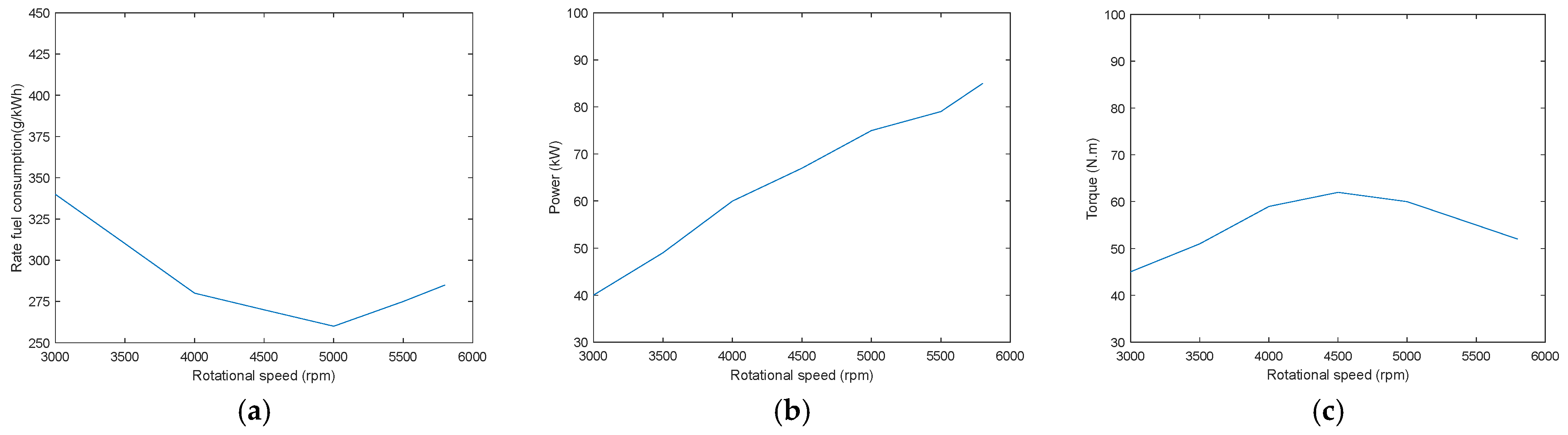
- Engine model
- (2)
- Fuel-cell model
- (3)
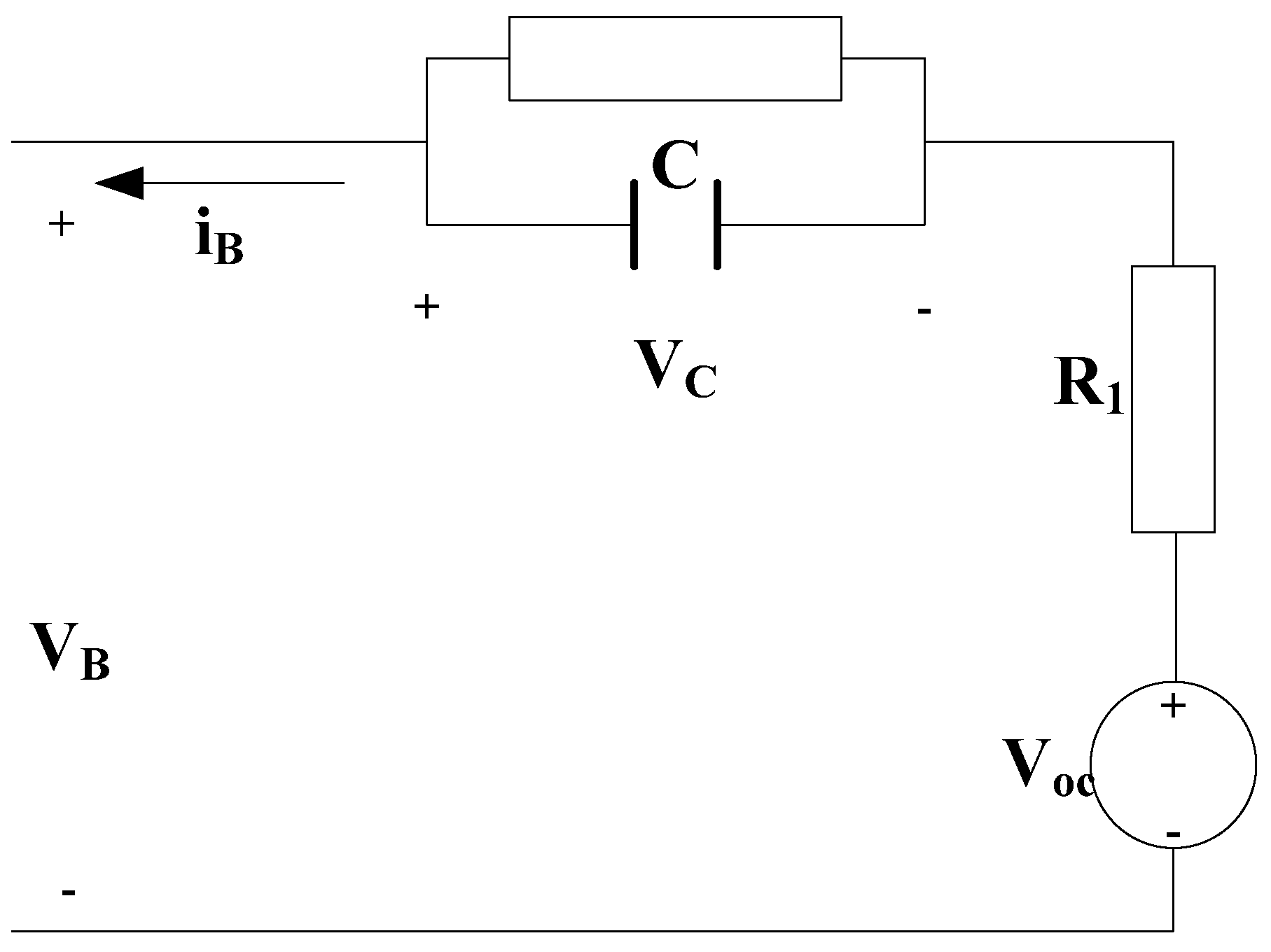
- Lithium-ion battery model
- (4)
- Load model
- (5)
- Hydrogen hybrid energy system model
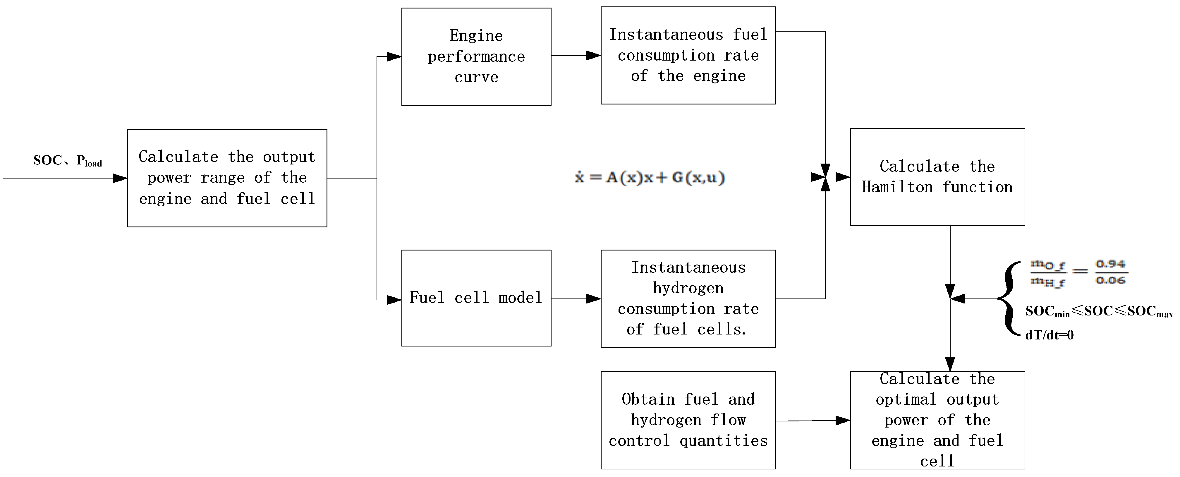
3. Energy Management Strategy
- (1)
- Calculate the output power range of the engine and fuel cell based on the overall power and SOC;
- (2)
- Calculate the transient fuel consumption rate of the engine and fuel cell using the engine characteristic curve and fuel-cell model;
- (3)
- Calculate the Hamilton function based on the transient fuel consumption rate of the engine and fuel cell as well as the state equation of the hydrogen hybrid energy system;
- (4)
- Calculate the optimal output power of the engine and fuel cell using the Hamilton function based on the constraint conditions;
- (5)
- Obtain fuel and hydrogen flow-control quantities based on the output power of the engine and fuel cell.
4. Simulation and Analysis
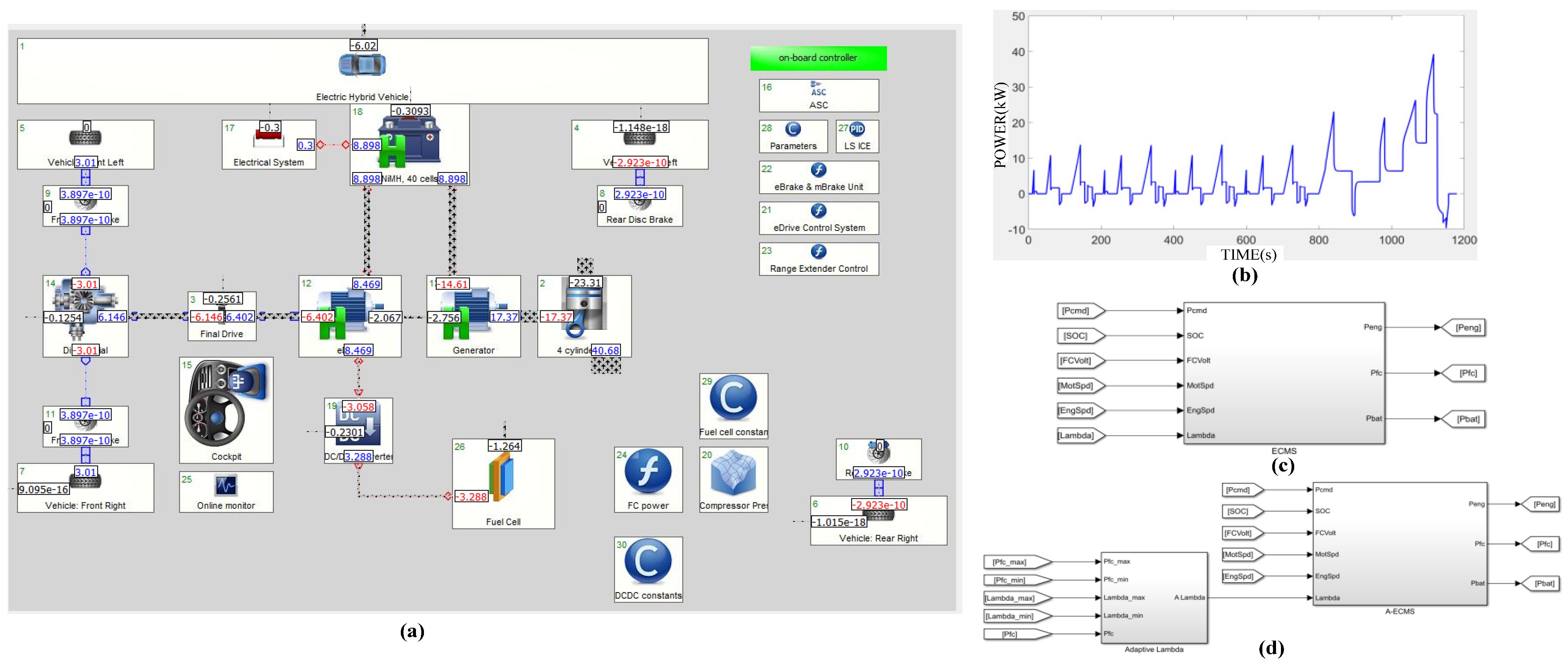
4.1. Simulation and Analysis Platform
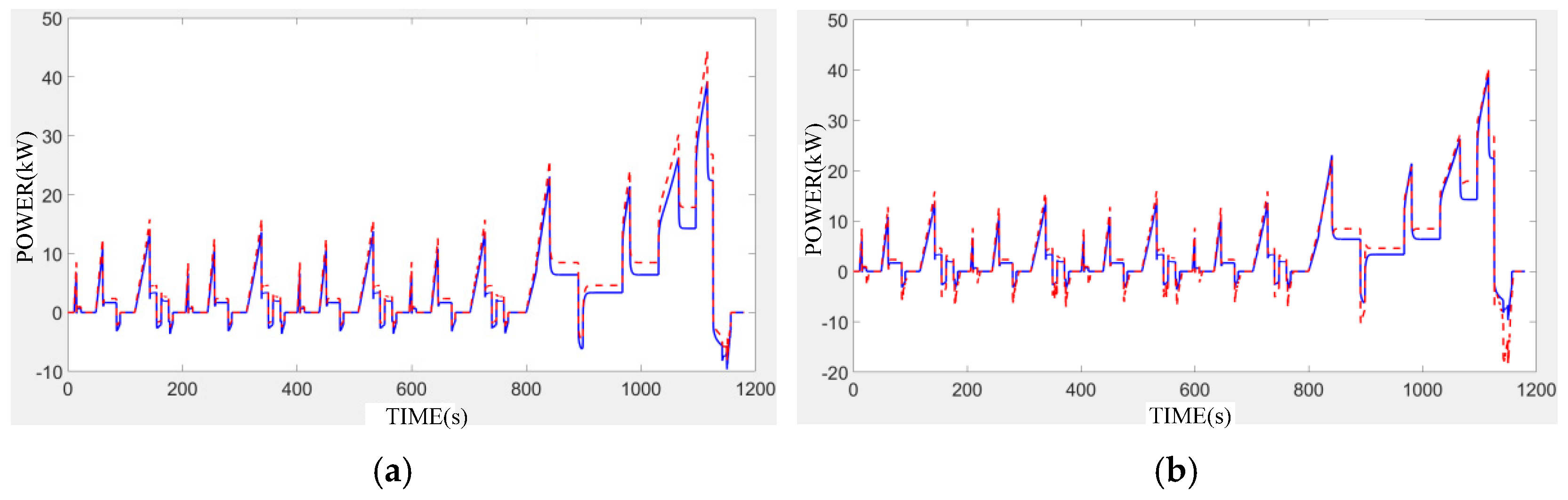
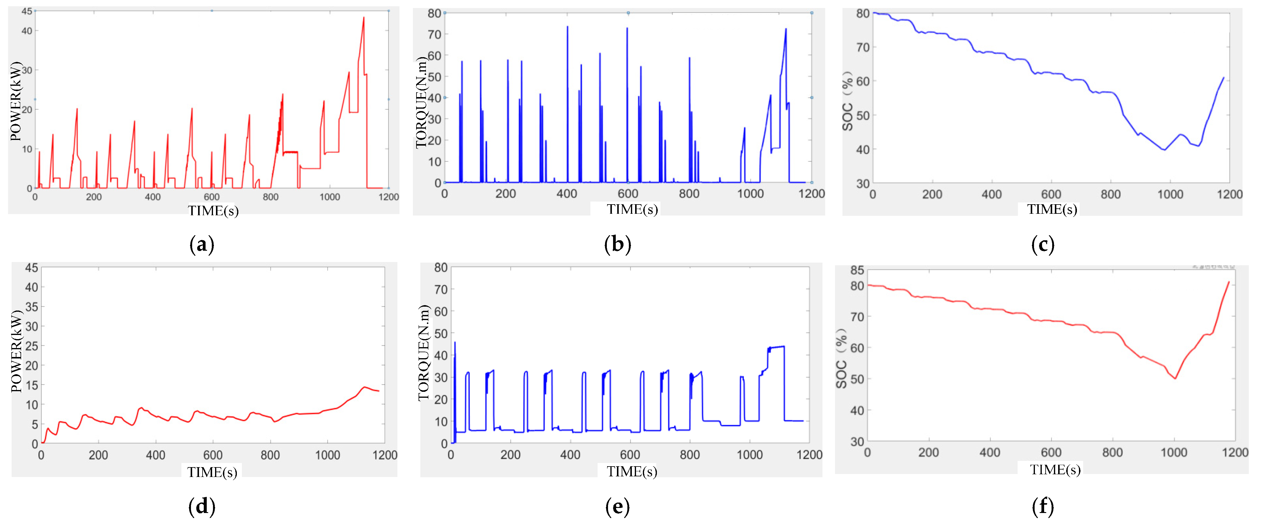
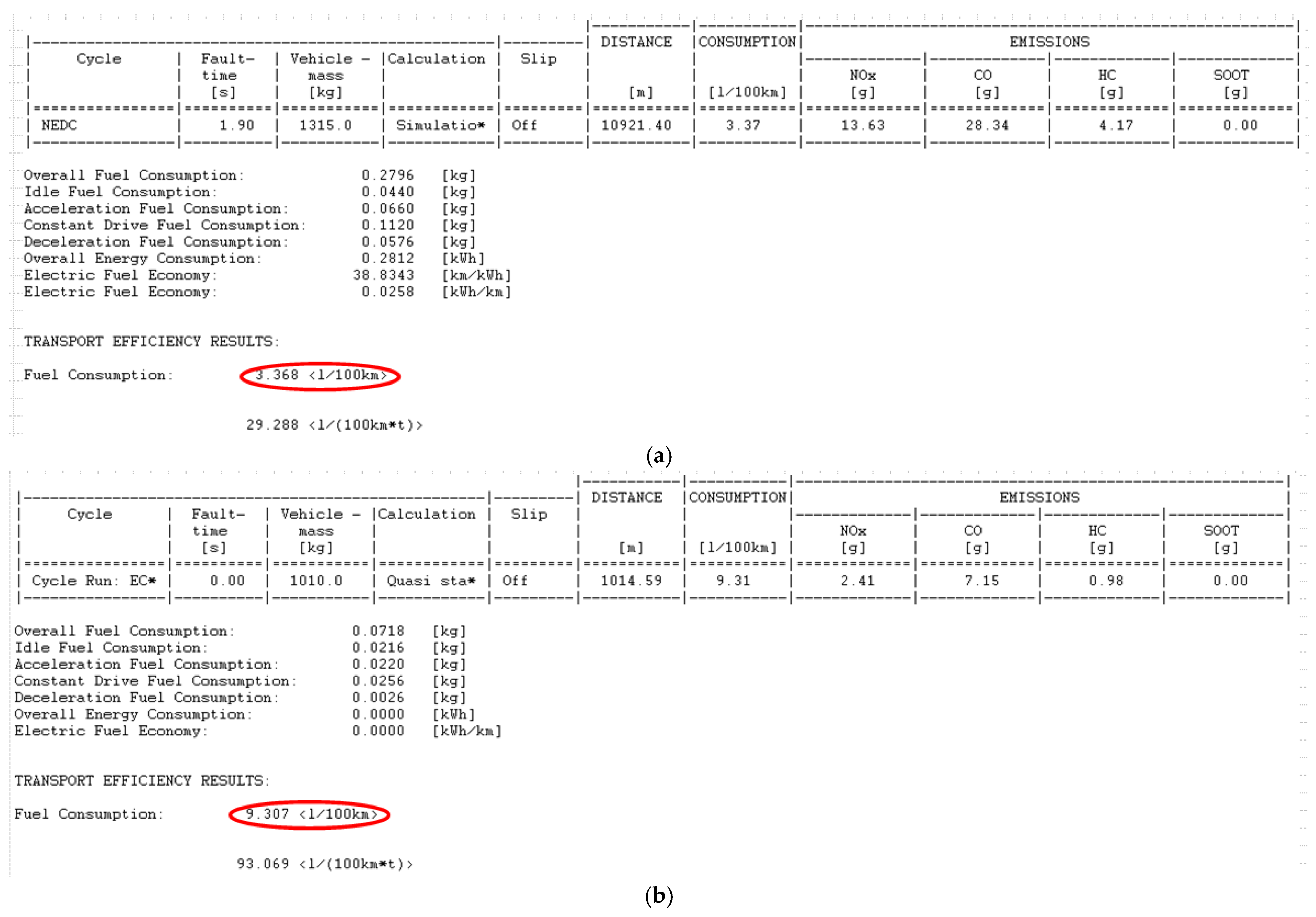
4.2. Simulation Analysis of Energy Management Strategy
5. Conclusions
Author Contributions
Funding
Data Availability Statement
Conflicts of Interest
References
- Chen, B.; Pan, X.; Evangelou, S.A. Optimal Energy Management of Series Hybrid Electric Vehicles with Engine Start–Stop System. IEEE Trans. Control. Syst. Technol. 2023, 31, 660–675. [Google Scholar] [CrossRef]
- Ghanem, C.R.; Gereige, E.N.; Bou Nader, W.S.; Mansour, C.J. Stirling system optimization for series hybrid electric vehicles. Proc. Inst. Mech. Eng. Part D J. Automob. Eng. 2022, 236, 407–423. [Google Scholar] [CrossRef]
- Du, G.; Zhang, G.; Yu, S.S.; Iu, H.H.; Lin, W.; Le, W.; Zhang, Y. An any-unit-to-any-unit method for hybrid-structured voltage equalizer in series-connected battery/super-capacitor strings. Int. J. Circuit Theory Appl. 2022, 50, 2016–2034. [Google Scholar] [CrossRef]
- Villani, M.; Shiledar, A.; D’Arpino, M.; Rizzoni, G. Battery Selection and Optimal Energy Management for a Range-Extended Electric Delivery Truck. SAE Int. J. Adv. Curr. Pract. Mobil. 2022, 5, 1282–1291. [Google Scholar] [CrossRef]
- Wahono, B.; Santoso, W.B.; Nur, A. Analysis of range extender electric vehicle performance using vehicle simulator. Energy Procedia 2015, 68, 409–418. [Google Scholar] [CrossRef]
- Li, X.; Evangelou, S.A. Torque-leveling threshold-changing rule-based control for parallel hybrid electric vehicles. IEEE Trans. Veh. Technol. 2019, 68, 6509–6523. [Google Scholar] [CrossRef]
- Cipek, M.; Pavković, D.; Petrić, J. A control-oriented simulation model of a power-split hybrid electric vehicle. Appl. Energy 2013, 101, 121–133. [Google Scholar] [CrossRef]
- Mechichi, O.; El Amraoui, L.; Trigui, R. Impact of Rule-based EMS parameters and charging strategies on Plug-in HEV efficiency. In Proceedings of the 2021 IEEE Vehicle Power and Propulsion Conference (VPPC), Virtual, 25 October–14 November 2021; pp. 1–6. [Google Scholar]
- Yadav, R.K.; Bharti, D.; De, M. Optimizing HEV Performance with Fuzzy Logic-Based PID Gain Tuning. In Proceedings of the 2023 3rd International Conference on Emerging Frontiers in Electrical and Electronic Technologies (ICEFEET), Patna, India, 21–22 December 2023; pp. 1–6. [Google Scholar]
- Srivastava, S.; Maurya, S.K. Power Flow Management in HEV using Adaptive Neuro-Fuzzy Controller. In Proceedings of the 2022 IEEE Students Conference on Engineering and Systems (SCES), Prayagraj, India, 1–3 July 2022; pp. 1–6. [Google Scholar]
- Song, Z.; Zhang, X.; Li, J.; Hofmann, H.; Ouyang, M.; Du, J. Component sizing optimization of plug-in hybrid electric vehicles with the hybrid energy storage system. Energy 2018, 144, 393–403. [Google Scholar] [CrossRef]
- Alegre, S.; Míguez, J.V.; Carpio, J. Modelling of electric and parallel-hybrid electric vehicle using Matlab/Simulink environment and planning of charging stations through a geographic information system and genetic algorithms. Renew. Sustain. Energy Rev. 2017, 74, 1020–1027. [Google Scholar] [CrossRef]
- Wang, Y.; Jiao, X. Dual heuristic dynamic programming based energy management control for hybrid electric vehicles. Energies 2022, 15, 3235. [Google Scholar] [CrossRef]
- Ouyang, M.; Feng, X.; Han, X.; Lu, L.; Li, Z.; He, X. A dynamic capacity degradation model and its applications considering varying load for a large format Li-ion battery. Appl. Energy 2016, 165, 48–59. [Google Scholar] [CrossRef]
- Pei, P.; Chang, Q.; Tang, T. A quick evaluating method for automotive fuel cell lifetime. Int. J. Hydrogen. Energy 2008, 33, 3829–3836. [Google Scholar] [CrossRef]
- Zhang, Y.; Chen, M.; Cai, S.; Hou, S.; Yin, H.; Gao, J. An online energy management strategy for fuel cell hybrid vehicles. In Proceedings of the 2021 40th Chinese Control Conference (CCC), Shanghai, China, 26–28 July 2021; pp. 6034–6039. [Google Scholar]
- Tian, S.; Cai, W. Energy Management Strategy for Hybrid Electric Vehicles Based on Whale Optimization Algorithm. In Proceedings of the 2023 3rd International Conference on Energy, Power and Electrical Engineering (EPEE), Wuhan, China, 15–17 September 2023; pp. 1226–1231. [Google Scholar]
- Guan, J.C.; Chen, B.C. Adaptive power management strategy based on equivalent fuel consumption minimization strategy for a mild hybrid electric vehicle. In Proceedings of the 2019 IEEE Vehicle Power and Propulsion Conference (VPPC), Hanoi, Vietnam, 14–17 October 2019; pp. 1–4. [Google Scholar]
- Shen, Z.; Luo, C.; Dong, X.; Lu, W.; Lv, Y.; Xiong, G.; Wang, F.Y. Two-level energy control strategy based on ADP and A-ECMS for series hybrid electric vehicles. IEEE Trans. Intell. Transp. Syst. 2022, 23, 13178–13189. [Google Scholar] [CrossRef]
- Picchirallo, A.; Anselma, P.G.; Belingardi, G.; Emadi, A. A component sizing oriented on-line controller for parallel hybrid electric vehicle powertrains based on the adaptive equivalent consumption minimization strategy. In Proceedings of the 2020 IEEE Transportation Electrification Conference & Expo (ITEC), Chicago, IL, USA, 23–26 June 2020; pp. 508–513. [Google Scholar]
- Gao, F.; Blunier, B.; Simoes, M.G.; Miraoui, A. PEM Fuel Cell Stack Modeling for Real-Time Emulation in Hardware-in-the-Loop Applications. IEEE Trans. Energy Convers. 2011, 26, 184–194. [Google Scholar] [CrossRef]
- Shanmuganathan, U.; Govarthanan, R.; Muthumailvaganan, A.; Imayakumar, A. Modeling and Dynamic Simulation of IC Engine Driven Permanent Magnet Generator Using Matlab/Simulink for Hybrid Tracked Vehicle. In Proceedings of the 2006 IEEE Conference on Electric and Hybrid Vehicles, Pune, India, 18–20 December 2006; p. 11. [Google Scholar]
- Zhou, B. Hybrid Electric Vehicle Energy Management Strategy with Consideration of Battery Aging. Ph.D. Thesis, Michigan Technological University, Houghton, MI, USA, 2020. [Google Scholar]


| Name | Symbol | Value | Unit |
|---|---|---|---|
| Maximum SOC | SOCmax | 30 | % |
| Minimum SOC | SOCmin | 80 | % |
| Torque resolution | T | 0.01 | N*m |
| Power resolution | P | 0.01 | Kw |
| ECMS | A-ECMS | |||||
|---|---|---|---|---|---|---|
| Cycle | NEDC | FTP75 | EUDC | NEDC | FTP75 | EUDC |
| H2 consumptions per 100 km (kg) | 0.217 | 0.205 | 0.219 | 0.198 | 0.193 | 0.200 |
| Fuel consumptions per 100 km (L) | 4.49 | 4.31 | 4.60 | 4.04 | 3.88 | 4.09 |
| Fuel consumptions per 100 km (kg) | 3.233 | 3.101 | 3.312 | 2.910 | 2.794 | 2.945 |
| Mass ratio of hydrogen to oil | 0.067 | 0.066 | 0.066 | 0.068 | 0.069 | 0.068 |
| Different from reference ratio | 0.003 | 0.002 | 0.002 | 0.004 | 0.005 | 0.004 |
Disclaimer/Publisher’s Note: The statements, opinions and data contained in all publications are solely those of the individual author(s) and contributor(s) and not of MDPI and/or the editor(s). MDPI and/or the editor(s) disclaim responsibility for any injury to people or property resulting from any ideas, methods, instructions or products referred to in the content. |
© 2025 by the authors. Licensee MDPI, Basel, Switzerland. This article is an open access article distributed under the terms and conditions of the Creative Commons Attribution (CC BY) license (https://creativecommons.org/licenses/by/4.0/).
Share and Cite
Zhu, Z.; Yin, Z.; Qin, K. Research on Energy Management Strategy Based on Adaptive Equivalent Fuel Consumption Minimum for Hydrogen Hybrid Energy Systems. Energies 2025, 18, 1691. https://doi.org/10.3390/en18071691
Zhu Z, Yin Z, Qin K. Research on Energy Management Strategy Based on Adaptive Equivalent Fuel Consumption Minimum for Hydrogen Hybrid Energy Systems. Energies. 2025; 18(7):1691. https://doi.org/10.3390/en18071691
Chicago/Turabian StyleZhu, Zhaoxuan, Zhiwei Yin, and Kaiyu Qin. 2025. "Research on Energy Management Strategy Based on Adaptive Equivalent Fuel Consumption Minimum for Hydrogen Hybrid Energy Systems" Energies 18, no. 7: 1691. https://doi.org/10.3390/en18071691
APA StyleZhu, Z., Yin, Z., & Qin, K. (2025). Research on Energy Management Strategy Based on Adaptive Equivalent Fuel Consumption Minimum for Hydrogen Hybrid Energy Systems. Energies, 18(7), 1691. https://doi.org/10.3390/en18071691