1. Introduction
Wind power generation is mostly DC power that cannot be directly incorporated into the AC power grid, and the converter device needs to be connected to the grid after the DC–AC conversion. As a mature device, the inverter plays an important role in fan grid connection [
1]. Therefore, in order to maintain the stability and safety of the large power grid’s operation, it is necessary to ensure the performance of the inverter. The inverter output signal for the pulse signal, doping interference in power transmission, dead time, and guided custom clearance break time delays will cause harmonics, harmonics will reduce the power quality and the service life of equipment, and this will cause serious equipment damage and power supply system paralysis. So, on the basis of considering the performance and cost, we need to choose the appropriate filter to make sure the power quality meets the requirements of the grid connection [
2,
3,
4]. Currently, the high-frequency oscillations in power systems are usually handled by external methods, such as tripping protection and changing the operating modes of units. However, these methods reduce industrial production efficiency and are not conducive to the integration of new energy. Therefore, it is necessary to suppress high-frequency oscillations from within the system.
High-frequency oscillations, also known as high-frequency resonances, are likely to occur when the system uses dual-loop control of voltage and the current. In contrast, when using voltage amplitude control, the output impedance is approximately the filter impedance at high frequencies [
5], making the occurrence of high-frequency oscillations less likely. The formation mechanisms of high-frequency oscillations can be mainly divided into two types: the inherent resonance of the LCL filter [
6,
7] and the negative damping introduced by digital control delay at high frequencies [
8,
9], both of which can trigger high-frequency oscillations when connected to the grid. There have been numerous research findings on suppressing high-frequency oscillations caused by these two factors, which can be summarized as two aspects.
Firstly, the passive damping scheme mainly improves the system through hardware circuits. For the inherent resonance of the LCL filter, passive damping involves connecting resistors in series or in parallel with the filter inductance or capacitance to suppress resonance peaks. Reference [
10] identifies six basic methods for suppressing LCL inherent resonance using passive damping, among which the scheme of connecting a resistor in series with the filter capacitance can achieve good resonance suppression with minimal loss. It is the most commonly used passive damping method. Further improvements can be made by splitting the filter capacitance or adding a bypass inductor/capacitor to the damping resistor to reduce the loss of the damping resistor. For high-frequency oscillations caused by negative damping due to digital control delay, passive damping involves adding passive circuits to the grid side of the converter to use its inherent positive damping to counteract the negative damping caused by the delay, keeping the output resistance of the grid-connected system in the positive resistance region and thus suppressing high-frequency oscillations [
11]. Passive damping is simple to implement and effective in suppression, but it increases the cost of hardware circuit construction and reduces the system’s power transmission efficiency due to the additional damping resistors [
12]. As an evolution of passive damping, active damping is mainly used to suppress high-frequency resonance phenomena.
Active damping, unlike passive damping, which changes the external structure of the circuit, usually introduces a damping branch into the internal control loop of the system to suppress high-frequency oscillations [
13]. Similarly, the forms of active damping vary for high-frequency oscillations caused by different mechanisms. For the inherent resonance peak of the LCL filter, the basic idea of active damping is to simulate passive damping by selecting appropriate state variables for additional control to achieve high-frequency resonance suppression [
14].
Therefore, we can analyze the combination of active and passive damping. The literature [
15] states that active damping can be transformed using the control block diagram, which is equivalent to the same form of control as passive damping. Similar to the damping resistance in the passive damping scheme, the active damping scheme can obtain different virtual impedance through block diagram transformation, and the virtual resistance part can have an inhibitory effect on high-frequency resonance. In the literature [
16], power grid current control and the inverter current control are analyzed relatively from the perspective of power grid current stability based on a general mathematical model. The literature [
17] proposes a new inverter current feedback resonance suppression method to reduce the grid impedance effect and resonant frequency shift. However, due to the mathematical limitation of solving the tertiary system eigenvalues, the design of the active controllers is more complex and lacks physical significance, especially when considering digital control delay. As for the high-frequency oscillation caused by digital control delay, the idea of the active damping scheme is to weaken the negative damping introduced by the control circuit by introducing the active damping introduced by the delay and then suppressing the high-frequency oscillation caused by negative damping [
18,
19,
20].
In summary, with the continuous increase in the penetration rate of new energy sources, power systems are increasingly exhibiting power electronic characteristics. The grid-connected inverter, as the energy conversion interface between new energy generation units and the power grid, plays a vital role in the stable and secure operation of power systems. This paper takes the LCL-type permanent magnet direct drive wind turbine grid-connected inverter as the research object and focuses on the analysis of high-frequency oscillation issues, which are more severe stability problems. Existing research on the suppression of high-frequency oscillations in power systems mainly focuses on two aspects: hardware circuit improvement (passive damping) and control strategy optimization (active damping).Therefore, this paper mainly focuses on the impedance remodeling of specific frequency bands and the impedance characteristics of other frequency bands, which may cause new oscillation problems in other frequency bands, namely the negative effect of the oscillatory suppression strategy. For this phenomenon, based on the negative effect mechanism research method, we first build the permanent magnet direct drive wind power grid-side inverter analysis model, combined with passive damping and active damping. We then derive the equivalent circuit using the active damping method between the damping factor and system oscillation, and we develop an argument based on the feasibility of the analysis of the oscillation negative effect suppression mechanism and the analysis of the corresponding improvement control scheme in order to improve the system’s stability and ensure the safety of the new energy grid.
2. Research on the Mechanism of Active Damping of High-Frequency Oscillations Based on the Damping Factor
2.1. Modeling and Control of a Permanent Magnet Direct Drive Wind Power Generation System
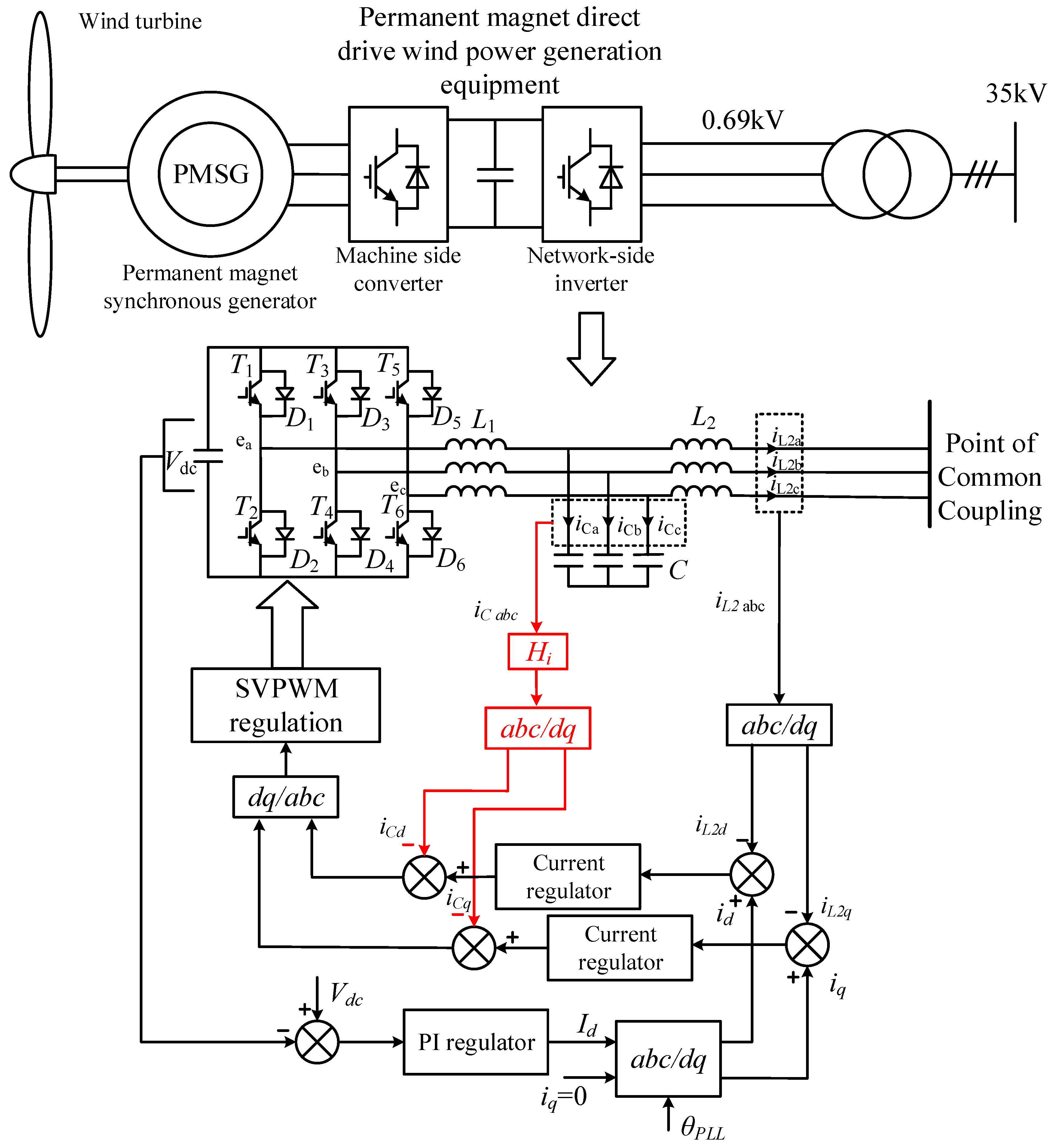
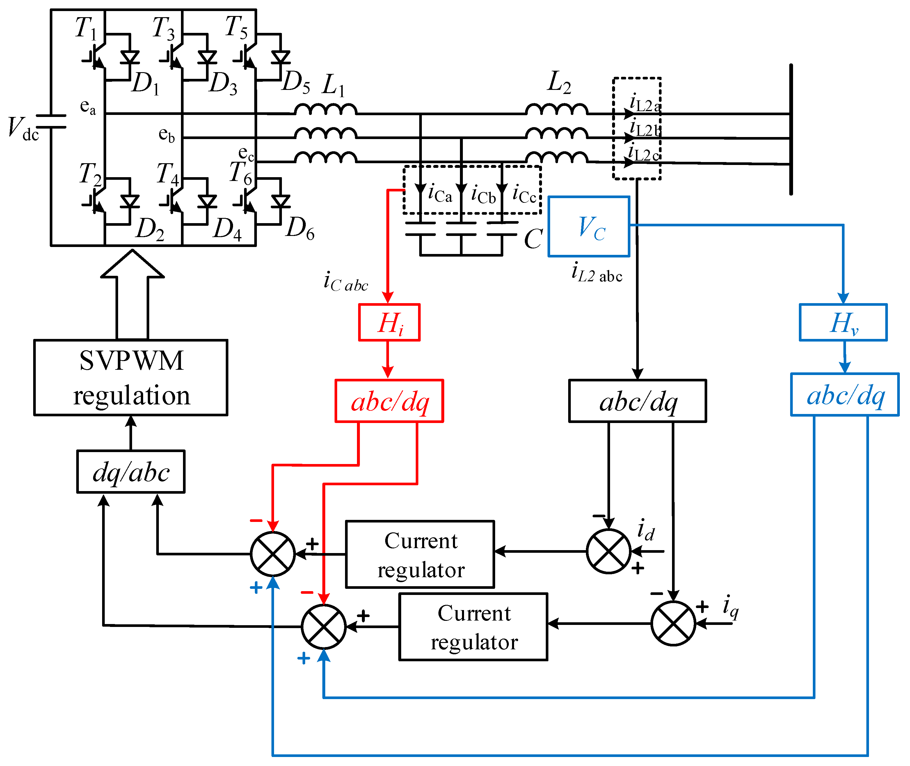
Permanent magnet direct drive wind power generation equipment is adopted, and the network-side inverter current feedback has active damped CCFAD (capacitive current feedback active damping) control. The topology and control block diagram are shown in
Figure 1.
To simplify the analysis, the assumptions for the system are as follows: (1) all power switches are ideal switches, ignoring the influence of the switch dead zone; (2) filter inductance and capacitance are ideal components and contain no parasitic resistance; and (3) the power grid’s voltage is three-relative ideal sine wave.
The analysis of the negative effect of the oscillation suppression strategy is mainly conducted for the network-side converter.
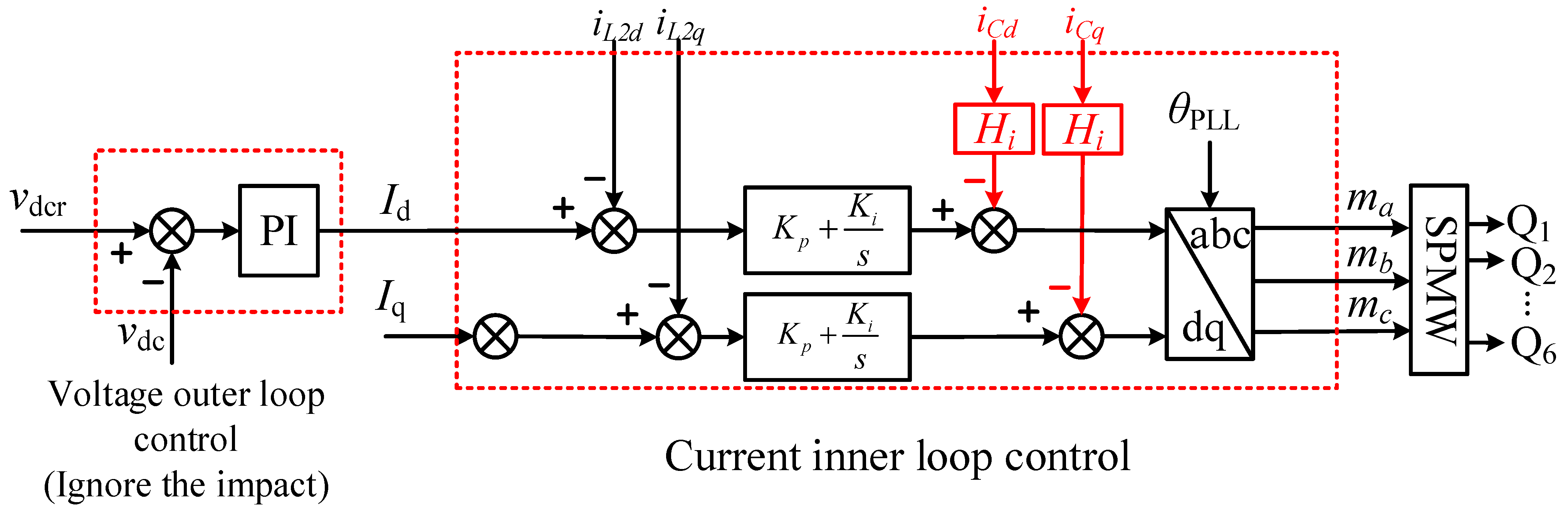
Figure 2 shows that
is the voltage command on the DC side of the network-side converter;
is the voltage on the DC side of the network-side converter;
and
are the output current commands of the
d axis and the
q axis under the synchronous rotation coordinate system;
is the capacitive current feedback active damping feedback coefficient;
and
are the current control ratio and the integral coefficient;
and
are the feedback values of the
d-axis and
q-axis grid-connected currents;
and
are the feedback values of the d-axis and the q-axis of the capacitor current; and
are the IGBT driving signals in the network-side converter.
For permanent magnet direct drive wind power PWM generation equipment modeling, because the fan rectifier and the network-side converter between the large DC capacitor connection, in stable operation, and the DC-side voltage fluctuation is very small, the DC side has a stable value, so the network side’s converter voltage control outer ring in impedance modeling is negligible, which can reduce modeling difficulty. Therefore, this paper mainly takes the current inner loop as the analysis object and ignores the voltage outer loop.
2.2. Active Damping Factor Based on the CCFAD Method
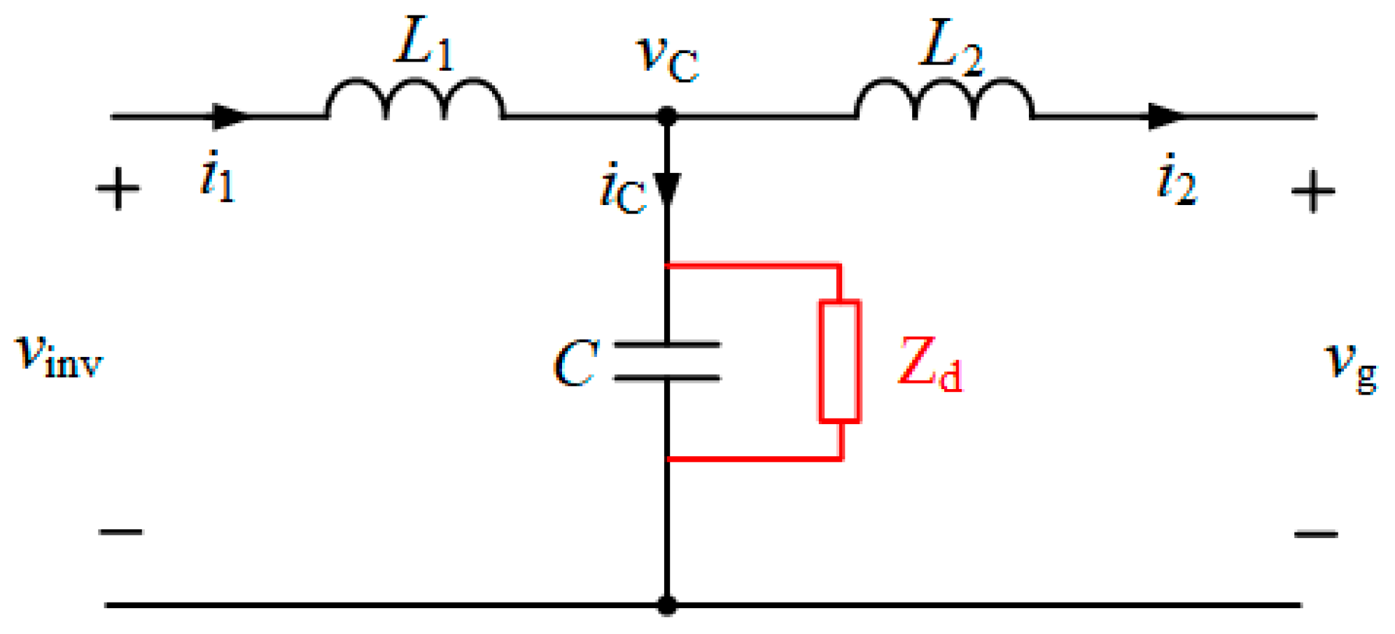
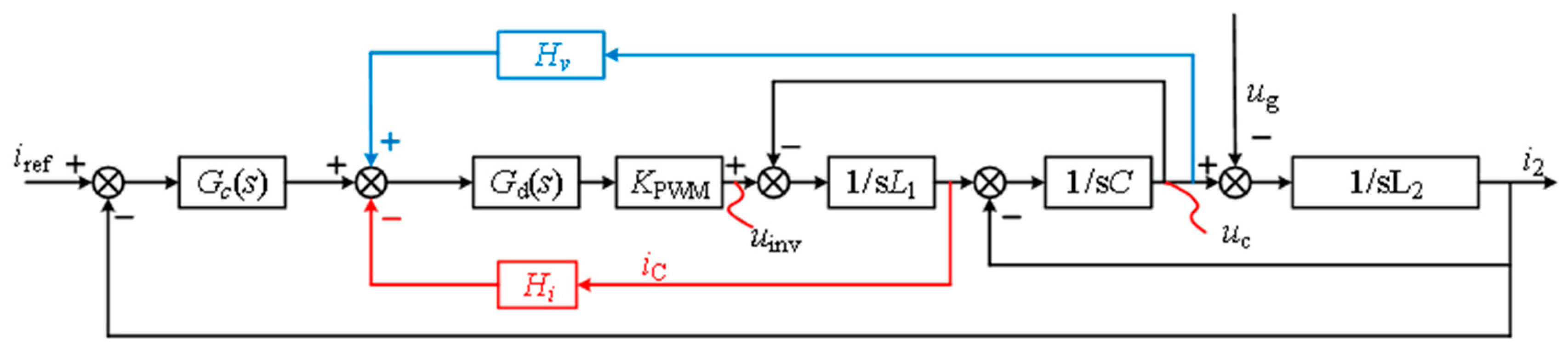
First, the transfer functions of passive damping and active damping are derived, and, by comparing the two transfer functions, the physical significance of the active damping suppression strategy is clarified, as shown in
Figure 3.
Next, the transfer function and the damping factor of the passive damping suppression strategy based on the series resistance of the grid-side inverter inductance are derived.
Corresponding to the above figure, the transfer function from
to
, the natural oscillation point of passive damping, and the damping factor can be derived as follows:
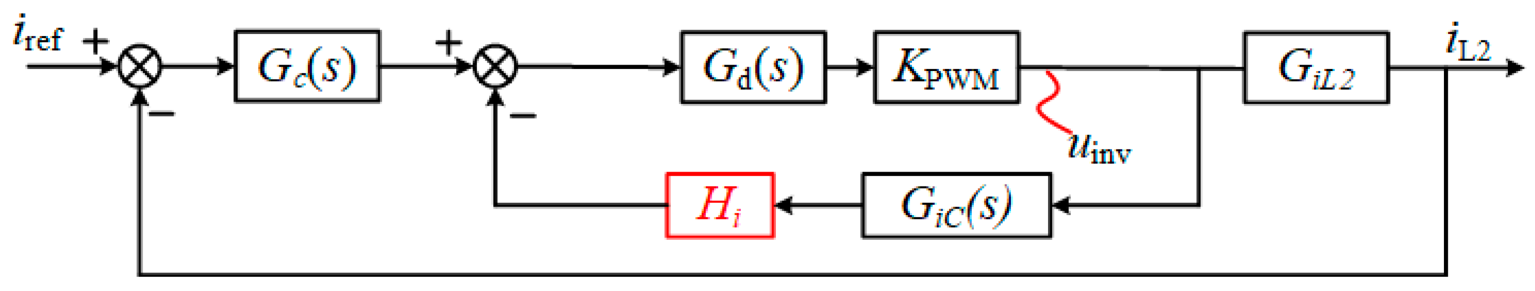
Based on the derivation of the damping factor and the transfer function of the passive damping suppression strategy mentioned above, the following is the derivation of the transfer function of the active damping suppression strategy based on CCFAD.
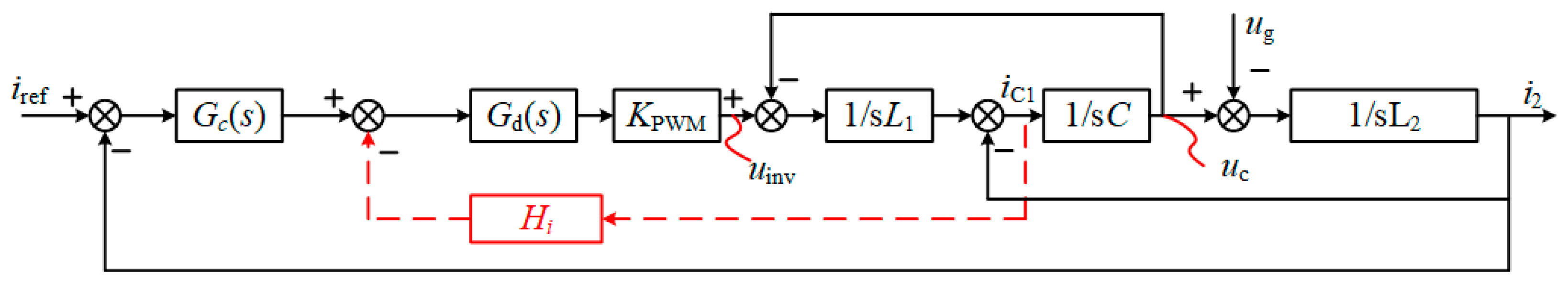
As shown in
Figure 4,
is the current regulator;
is the network-side inverter equivalent gain;
is the time delay; and
is the active damping feedback coefficient.
The PI controller
is used to track the reference current in a three-phase system with a synchronous rotation coordinate system.
PI parameters can be calculated using the same method as the standard L filter. Therefore, the proportional gain
is designed as Equation (5), where the crossover frequency
is recommended to be
[
19,
20]. Furthermore, the integration time constant is designed as Equation (6) to ensure that its phase contribution is small at the crossover frequency. Thus,
can be calculated as
.
where
is the ratio of the input voltage
and the triangular carrier amplitude
, namely
.
When asymmetric regular sampling is used, the calculation delay is one sampling period
, and the PWM modulation delay is an approximately 0.5 sampling period
, so the total digital control delay can be approximately expressed as
Furthermore,
Figure 2 can be obtained by treating the LCL-type filter as a whole. For the network-side inverter output-side voltage
, the network-side inverter current
, and the network-side current
, the specific expression is obtained through Equations (8) and (9).
Based on
Figure 5, the open-loop
gain expression is derived through Equation (10).
For simplicity, the open-loop transfer function from the grid-side inverter voltage to the grid-side current is defined as
The corresponding
with the passive damping transfer function can be obtained using a formula.
The damping factor of CCFAD can be obtained as
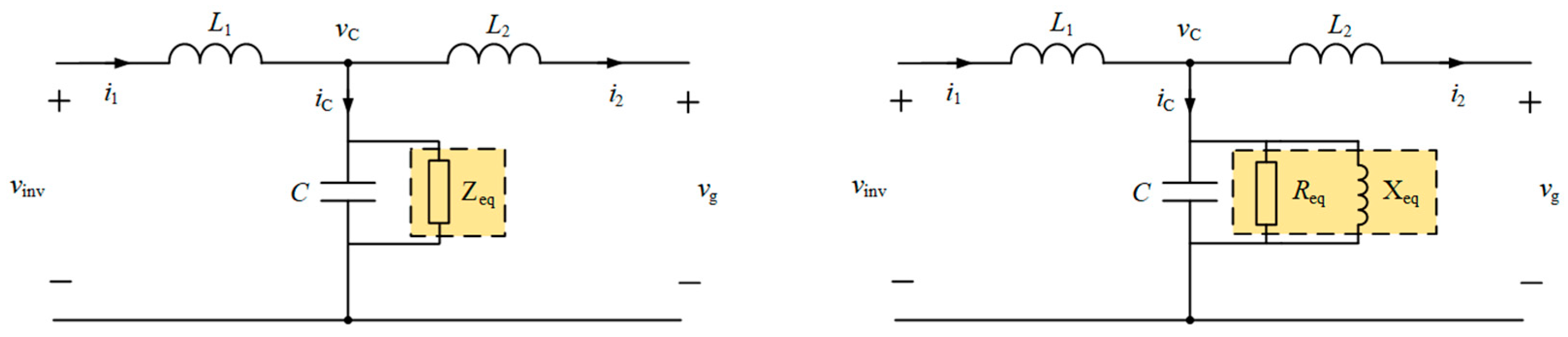
2.3. Equivalent Virtual Impedance Based on the CCFAD Method
Based on the passive damping suppression strategy of the inductor series resistance of the network-side inverter and the transmission function and damping factor of the active damping suppression strategy, the two correspond to the formula, and the equivalent form of the active damping suppression strategy in the physical model is defined.
Compared to undammed systems, CCFAD has an additional damping source,
. In order to obtain the same poles for the system based on the CCFAD method and the system in series with the network-side inverter-side damping resistor, which is the equivalent of the physical model of active damping, as shown in
Figure 6, the two damping factors should be equal, namely,
The Euler transform decomposes the virtual impedance
into
and
of the frequency domain, namely,
The equivalent virtual inductance value is
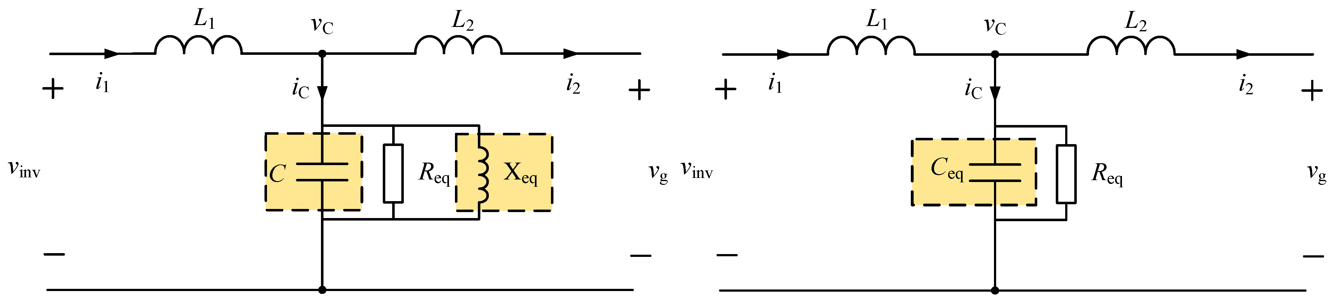
In this paper, the active damping equivalent virtual impedance is brought into the passive damping factor, and the equivalent damping factor is expressed as Equation (19).
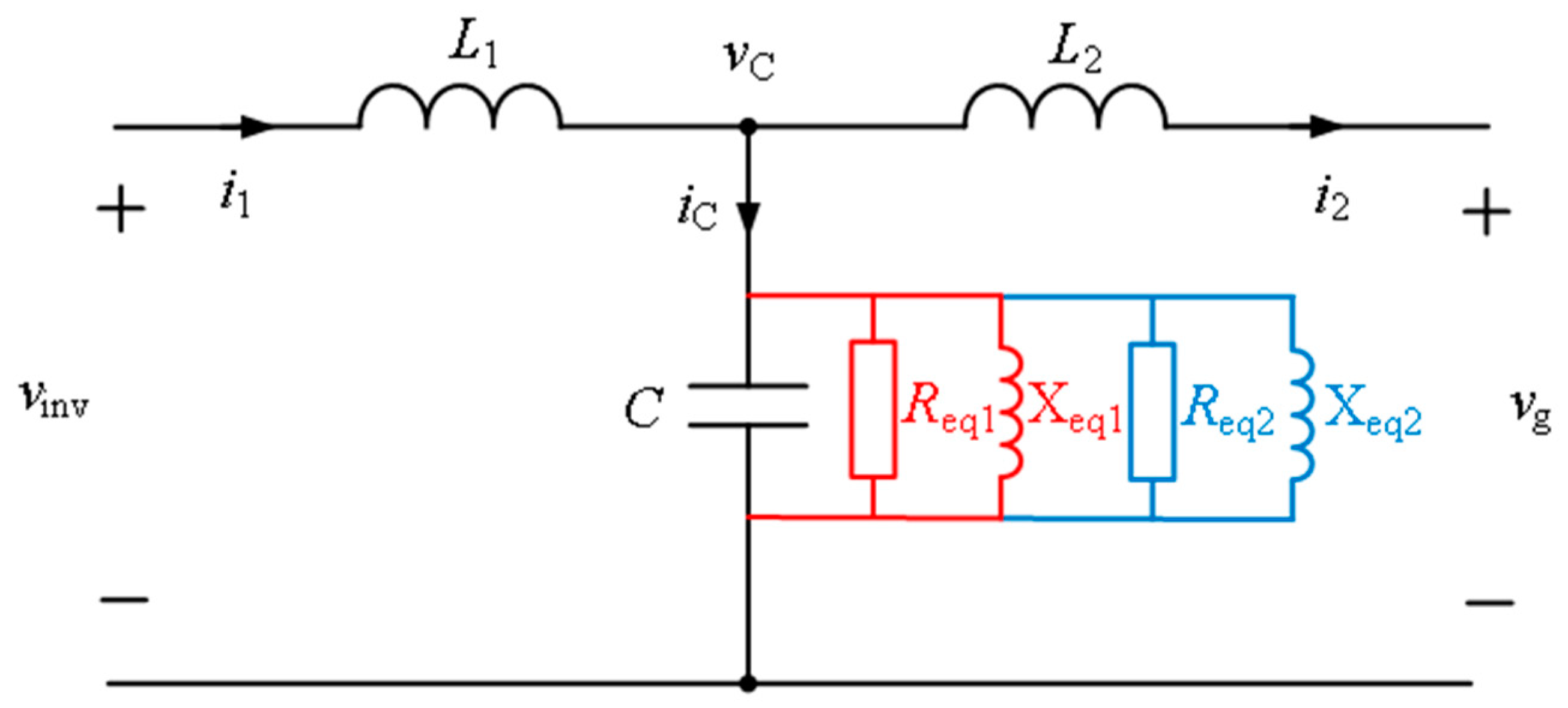
Thus, we stack the equivalent reactance of the active damping oscillation suppression strategy in parallel with C as shown in
Figure 7.
Therefore, the resonance frequency after applying active damping is
Therefore, the new resonance frequency is
The new resonance frequency expression is inserted into the Equations (14) and (17), and the active damping factor Equation (19) is
2.4. Analysis of the Mechanism of Negative Effects of the Oscillatory Inhibition Strategy Based on the Damping Factor
Based on the control theory, the magnitude of the damping factor scalar shows an obvious correlation between positive and negative and the inhibitory effect of , the system’s oscillation. In order to reveal how the system parameters of the network-side inverter affect system oscillation , the quantitative relationship between them, , should be studied. Obviously, when given the LCL filter parameters, network-side inverter gains, and the sampling frequency, the damping factor can be drawn for the existing resonance frequency. It should be noted that for the damping factor, the sign determines the number of poles in the right half-plane of the open ring, and the values reflect the damping effect. Therefore, it is best to be positive and as large as possible, which would be more conducive to resonance peak suppression.
Order
,
, select the LCL parameters,
,
, and
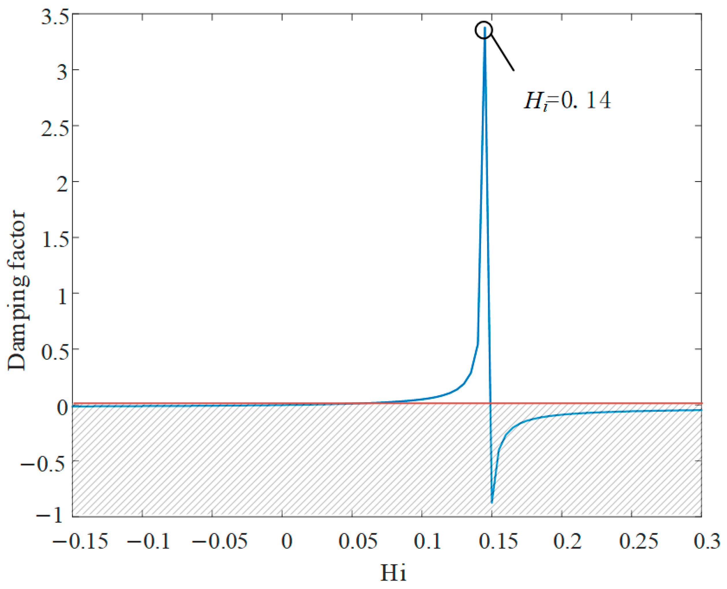
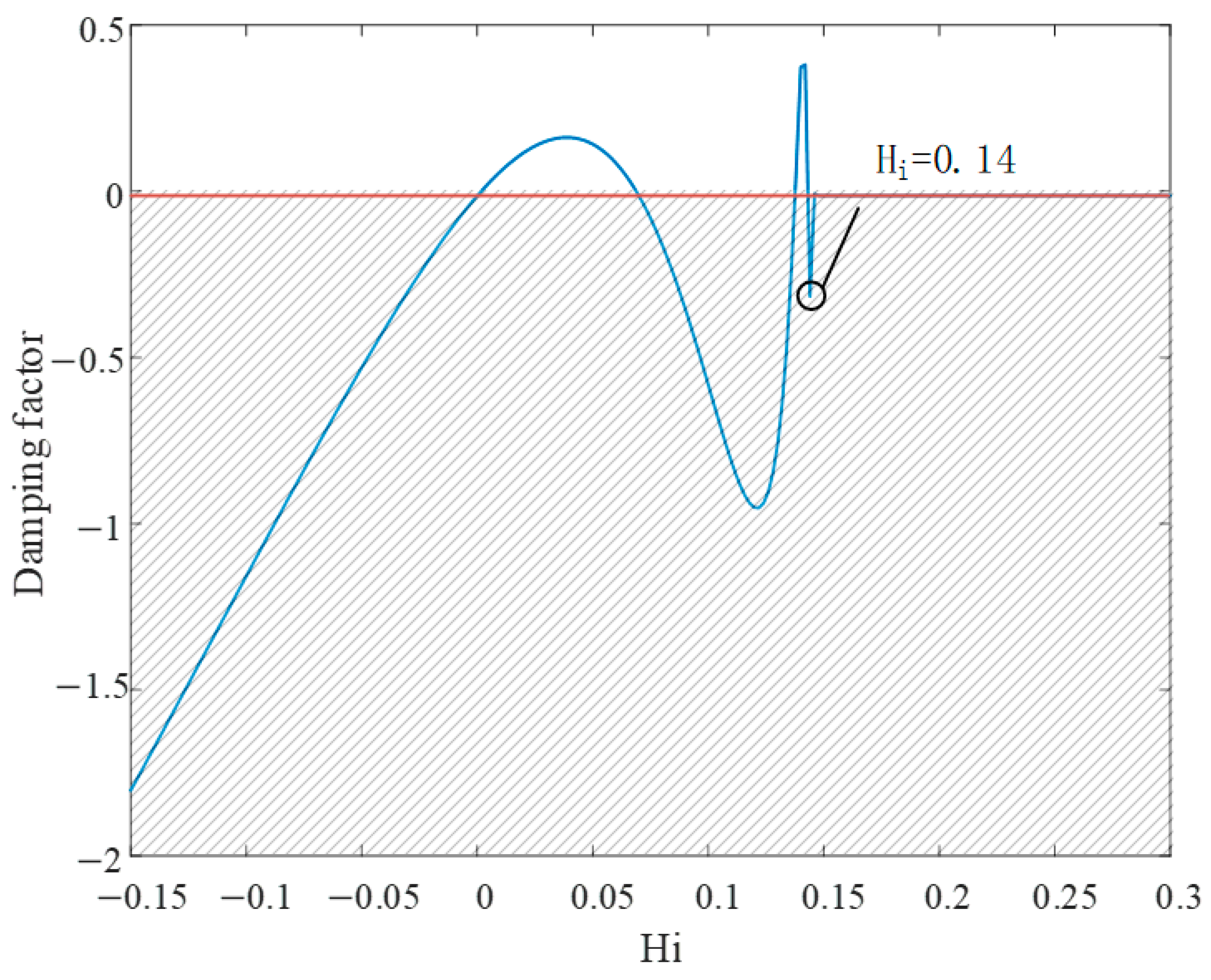
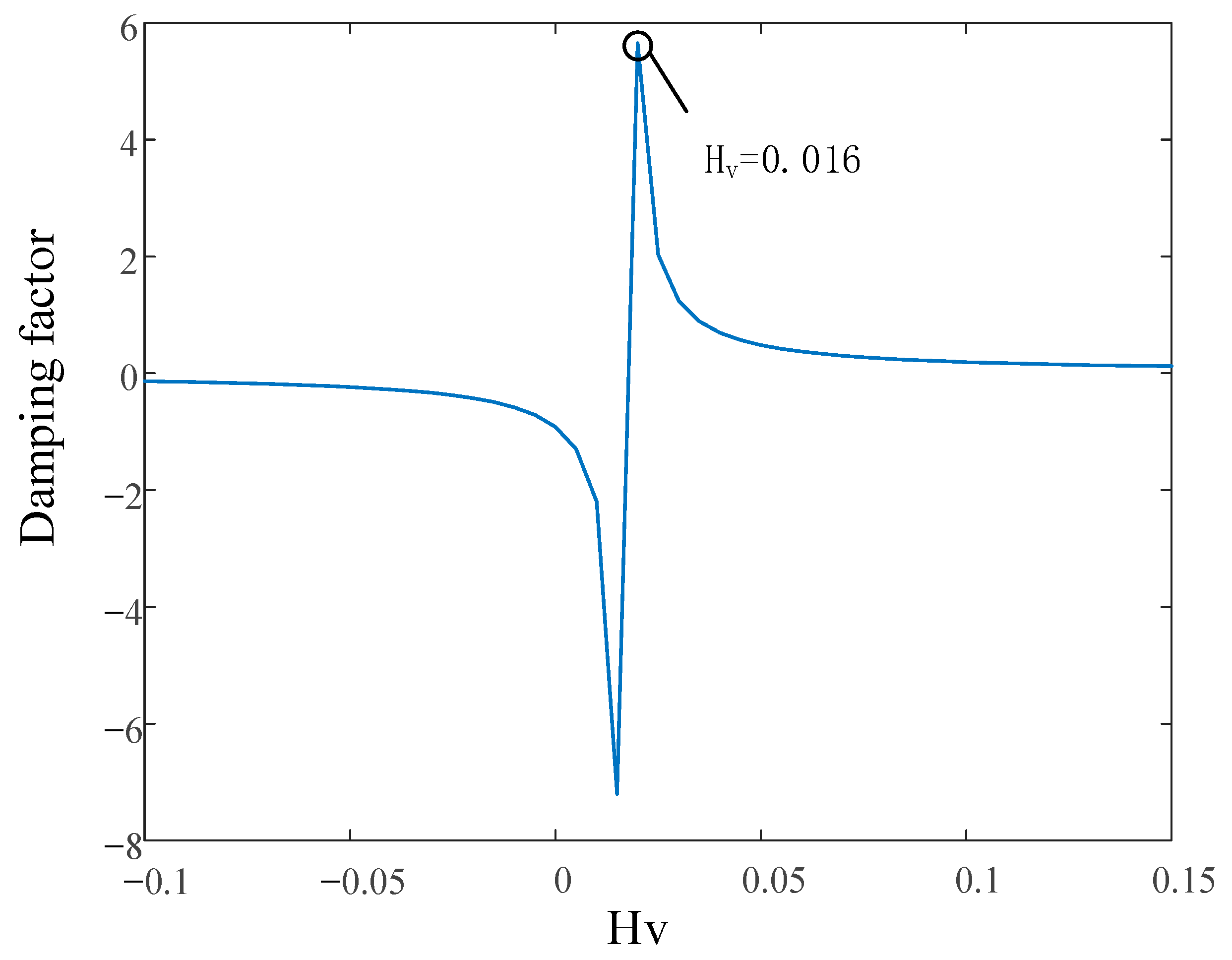
, not considering the change in grid impedance, bring the above parameters into Equation (20) to calculate the initial resonance frequency of the system, which is 1018 Hz, consider further perturbation, and draw the relationship between that and the damping factor (
Figure 8).
As it can be found from
Figure 8, when the frequency
of the initial working point is working at the initial resonance frequency, the damping factor increases with the active damping parameter and decreases. When
is greater than 0 and less than 0.14, the damping factor is positive and the system works stably, but when the damping factor exceeds the above category, the damping factor is negative, which causes the system’s stability to decrease, so the stability area of active damping is 0 to 0.14.
But, applying different active damping factors will shift the natural oscillation point. Therefore, from
Figure 8, select the best active damping parameter
and bring it into Equations (16) and (17). The corresponding resonant frequency
after the applied active damping is calculated, at which a characteristic curve after the applied active damping appears, is drawn in
Figure 9.
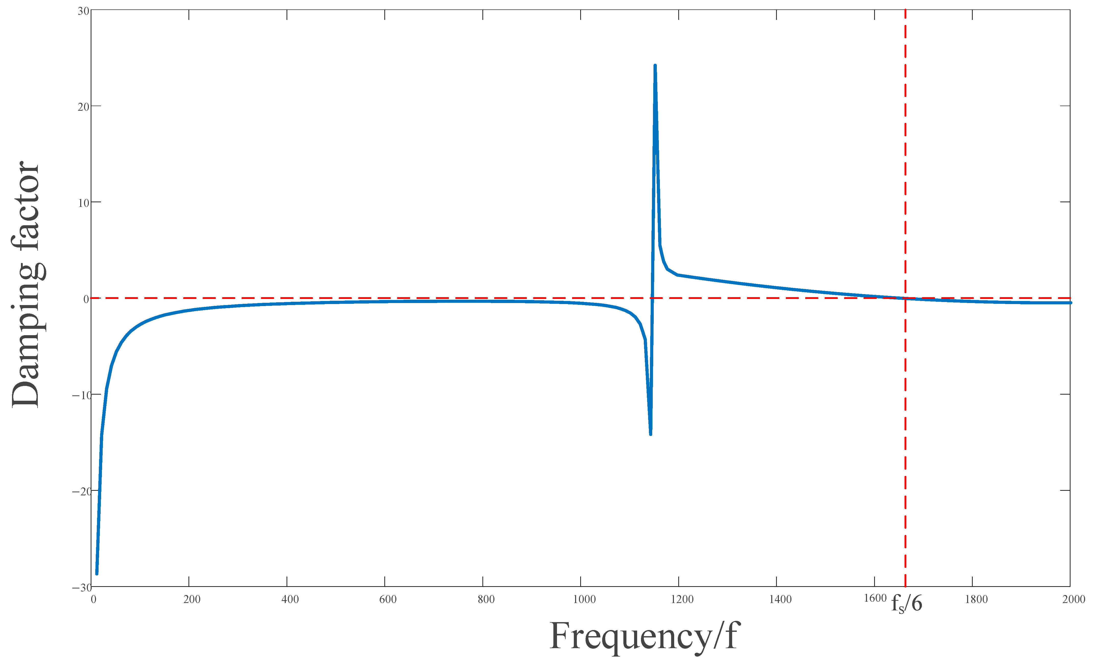
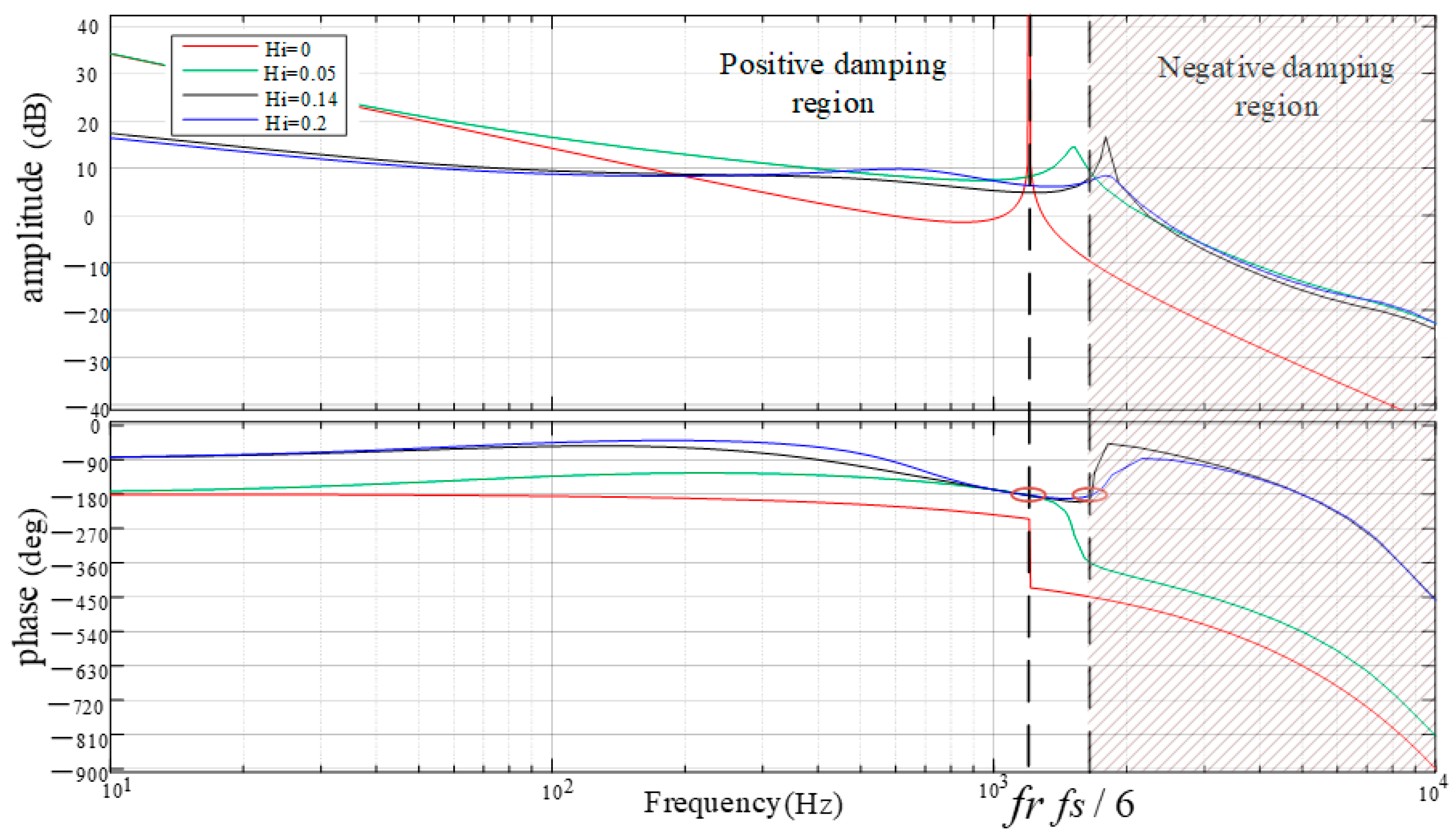
Secondly, according to Equations (16), (17) and (19), the frequency characteristic curve of the damping factor can be drawn, as shown in
Figure 10.
As it can be concluded from
Figure 9 and
Figure 10, the damping factor found in
shows the negative damping characteristics in the frequency band. The reason for this phenomenon is that the best damping parameter is inserted into Equation (22), the virtual impedance calculation, which causes
. Thus, the value of
is negative, eventually resulting in a negative value of
. The equivalent network-side inverter output inductance will be smaller than
, and the actual resonance frequency at this time is larger than the initial resonance frequency. Also, in this case, the molecular expression of the damping factor has a negative equivalent resistance, leading to a negative damping factor of the system at the new resonance frequency, causing new oscillation risks in the system. This causes system instability.
Based on the argument made on appeal, it is clear that the damping factor calculated through the equivalent circuit of the active inhibition strategy can reflect the steady state of the system with the corresponding frequency, while the parameters with additional active damping also have some relationship to the change in damping factor. Therefore, the damping factor is used as an indicator to analyze the phenomenon of the oscillatory suppression strategy, the negative suppression effect of an additional active/passive damping system. Based on traditional methods for portogram-based analysis in alternative impedance modeling, the simultaneous damping factor is a concept in control theory. It also makes the analysis process more concise and clear for the analysis of stable characteristics of the oscillatory inhibition strategy and the mechanism of negative effects, and it provides new ideas.
3. Active Damping Superposition Optimization Controls
When only a single state variable is used as the damping source, the system’s resonant frequency is offset due to the addition of active damping, and the new resonant frequency is determined through multiple factors. For the resonance point offset problem, this section proposes the control strategy of active damping superposition and introduces CVFFAD (Capacitor Voltage Feedforward active damping) on the basis of the original CCFAD. The negative effect of active damping is solved through the interaction of two active damping types. This section will discuss the overlay damping ability of capacitors’ current ratio feedback and capacitor voltage ratio feedforward and the design scheme of active damping proposed to achieve the strong damping characteristic of the inverter. Furthermore, the implementation mode of superimposed damping is analyzed.
Figure 11 shows the control structure diagram of capacitive current proportional feedback and the feedforward grid-connected inverter.
Figure 12 shows the system control block diagram of active damping superposition.
In
Figure 11, in addition to the addition of capacitor voltage active
feedforward (blue part), the rest is the parameters used in the previous CCFAD, in which the current regulator includes the current PI controller. Capacitive current feedback parameters
: The virtual damping resistor is directly introduced to reduce the impedance peak of the LCL filter at the resonant frequency and to suppress the accumulation of resonant energy. Capacitor voltage feedforward parameters
: The grid voltage disturbance is compensated by feedforward, which offsets the excitation effect of impedance change caused by CCFAD on resonance and further weakens the resonance risk. The combination of the two can form complementary damping near the resonant frequency band and improve the stability of the high-frequency band.
The
and
in
Figure 12 are the transfer function of the inverter voltage to the active damping feedback and the feedforward state variables, respectively. The open ring gain is obtained through Equation (26).
The specific expression of the transmission function of the network-side inverter output-side voltage
to the capacitance voltage
is obtained through Equation (27).
Simplify the
LCL filter transfer function under the active damping superposition control strategy.
Substituting Equations (8), (9) and (27) into Equation (28) gives Equation (29).
Equation (29) is analyzed.
is the active damping introduced by CCFAD, and the virtual impedance is obtained through Equations (16) and (17), recorded as
and
respectively;
is the active damping introduced by CVFFAD, and the virtual impedance is recorded as
and
respectively.
The two groups of active damping work together, and the virtual impedance of the two groups is simultaneously connected at both ends of the filter capacitor. The capacitor of LCL itself forms a new equivalent reactance
, as shown in
Figure 13.
The virtual impedance after active damping superposition is
Combine Equations (16), (17), (31) and (32) to obtain the combined damping factor through Equation (34). At this point, the damping resistance and the damping factor are jointly determined through CCFAD and CVFFAD.
Table 1 shows the detailed parameters of the grid-connected inverter design. The parameters in
Table 1 were inserted separately into Equation (35) to plot the relationship between
and damping factors, as shown in
Figure 14.
It can be found from
Figure 14 that when the damping factor is at the maximum the system works stably. However, when the feedback coefficient of CCFB and the feedforward coefficient of CVFF meet Formulas (2)–(36), the virtual reactance corresponding to
and
happens in parallel resonance, and the impedance of
and
in parallel is infinite, which is equivalent to an open circuit.
Through calculation, it is concluded that when , the virtual reactance and just have parallel resonance, so the intrinsic resonance frequency of the grid-connected inverter does not shift, which is consistent with the conclusion of the active superposition damping factor.
Table 2 satisfies Equation (36), and the damping factor is greater than 0 (Equation (35) > 0) and takes the values of
and
in different frequency ranges. From
Table 2, we can see that the
sign does not change in the range of
. Therefore, the active damping superposition control effectively expands the positive damping region of the damping factor, making the new control strategy an effective positive damping region
.
5. Conclusions
With the increasing proportion of new energy and power electronic equipment in the new power system, the threat of high-frequency oscillation to the stability of the power grid is becoming more and more significant. In this paper, the high-frequency oscillation suppression strategy of the grid-connected inverter of the permanent magnet direct drive wind turbine generator is studied. The negative effects of the existing active damping strategy on the impedance characteristics of other frequency bands (i.e., ‘negative effects’) when suppressing the oscillation in a specific frequency band are analyzed. An optimal control strategy based on active damping superposition is proposed to solve the problem of negative effects and improve the overall stability of the system.
- (1)
The mathematical model of the grid-connected inverter of a permanent magnet direct drive wind power generation system is established. Combined with the equivalent circuit of passive damping and active damping, the relationship between the damping factor and system oscillation is deduced. By comparing and analyzing the characteristics of the original resonance point and the new resonance point, the mechanism of the negative effect caused by the active damping strategy is revealed; when the virtual impedance introduced by the suppression strategy exhibits negative damping characteristics in a specific frequency band, the system will cause a new oscillation risk at the offset resonance frequency.
- (2)
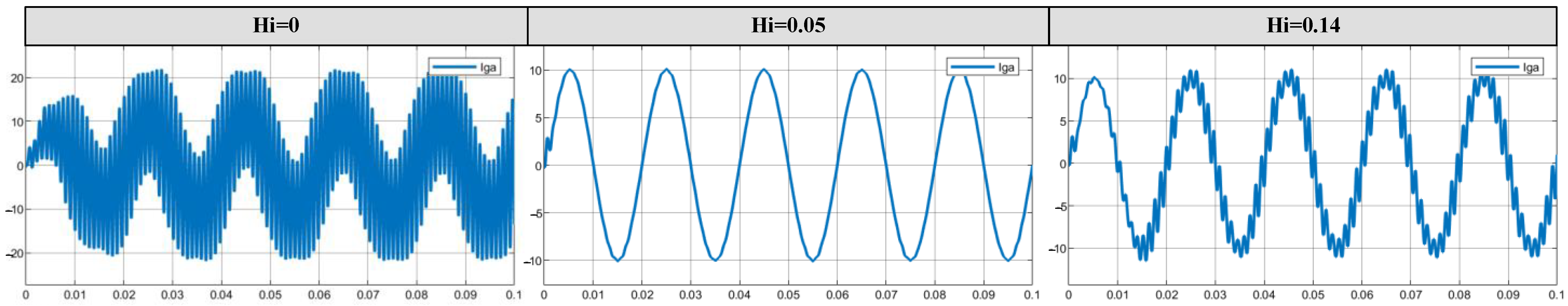
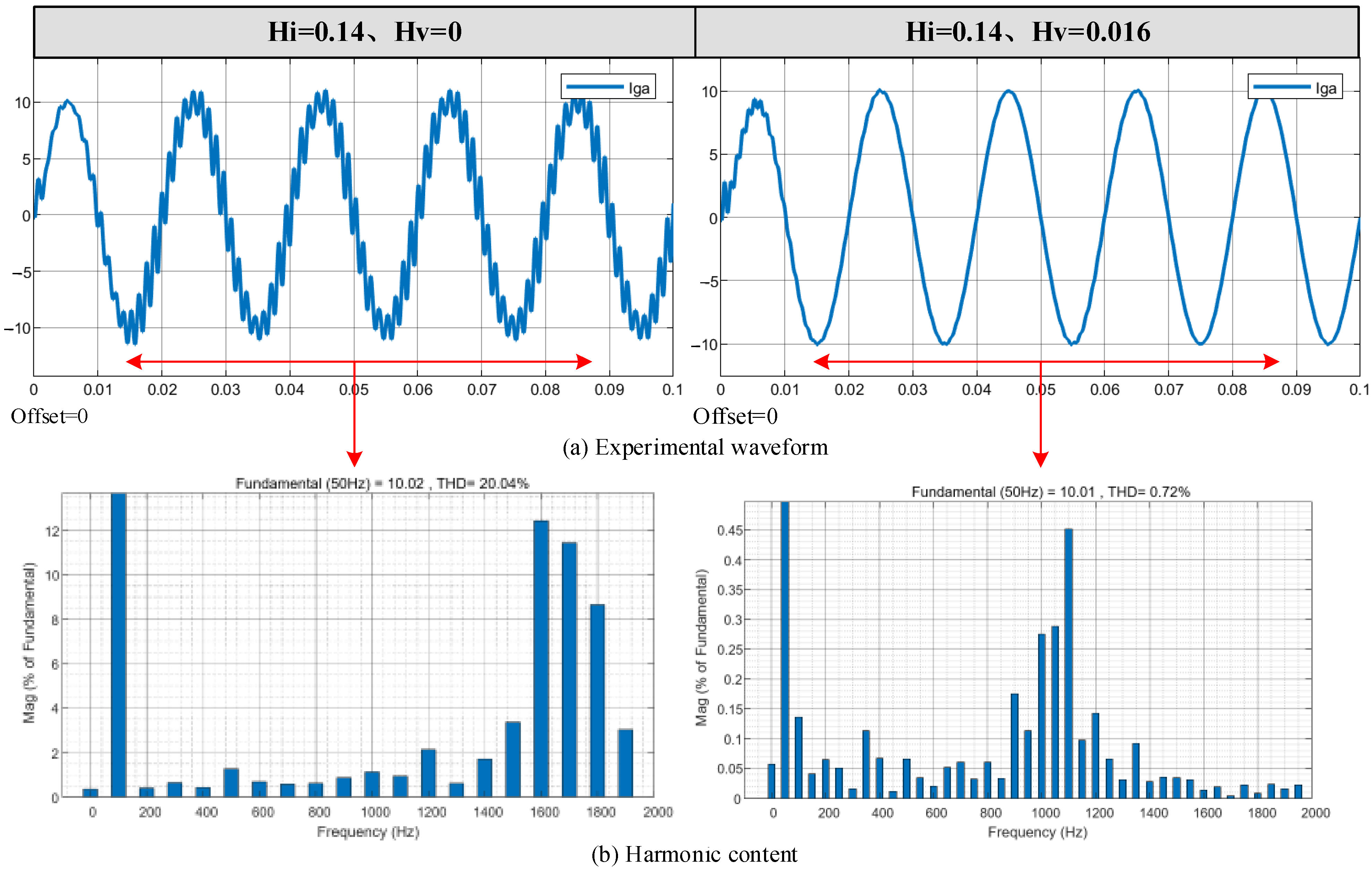
Aiming at the limitations of the traditional single active damping strategy, this paper proposes an active damping superposition control method combining capacitor current feedback (CCFAD) and capacitor voltage feedforward (CVFFAD). Through the complementary effect of the two damping sources, a positive damping region is formed near the resonance frequency band, which not only suppresses the original high-frequency oscillation but also avoids the generation of new resonance points. The simulation results show that the superposition control strategy significantly reduces the total harmonic distortion rate of the grid-connected current (THD decreases from 20.04% to 0.72%) and improves the dynamic response capability of the system.
- (3)
This paper innovatively uses the damping factor as an index to quantify the relationship between system stability and the oscillation suppression strategy. Through theoretical derivation and simulation verification, the direct correlation between the positive and negative damping factors and the stability of the system is clarified, which provides a simple and effective tool for analyzing the negative effect mechanism.
Although the methods proposed in this paper have achieved remarkable results at the theoretical and simulation levels, there are still the following deficiencies.
- (1)
Parameter optimization depends on ideal conditions: The design of control parameters is based on ideal assumptions (such as no distortion of grid voltage and no parasitic resistance of components), and more complex working conditions need to be considered in practical applications.
- (2)
Lack of hardware verification: The research mainly relies on the simulation platform, and the robustness of the strategy needs to be further verified using the experimental prototype.
- (3)
The multi-inverter parallel scenario is not involved: The current model does not consider the interaction of multi-inverters in parallel, and multi-inverter coupling in the actual wind farm may cause more complex oscillation problems.
Prospects for the next step include the following.
- (1)
In the future, an adaptive damping parameter adjustment mechanism can be designed in combination with artificial intelligence algorithms (such as the genetic algorithm and reinforcement learning) to cope with complex scenarios, such as dynamic changes in grid impedance and harmonic pollution. The experimental platform of the actual grid-connected inverter is built to verify the performance of the superposition control strategy in the real environment and optimize the hardware implementation scheme.
- (2)
Aiming at the multi-inverter parallel scenario in wind farms, the distributed cooperative control strategy is studied to solve the problem of resonance and harmonic superposition caused by multi-machine coupling. The current research focuses on high-frequency oscillation. In the future, suppression methods for medium–low-frequency oscillation (such as sub-synchronous oscillation) can be further explored to form a comprehensive suppression scheme covering the whole frequency band.


