
Full-Scale Experimental Assessment of a Horizontal-Axis Hydrokinetic Turbine for River Applications: A Challenge for Developing Countries


Abstract
1. Introduction
2. Challenges in Adapting Hydrokinetic Technology in Developing Countries
2.1. Energy Resource Assessment
2.2. Increasing Energy Density
2.3. Inadequate Research and Development
2.4. Hybrid Energy System Integration
2.5. Reliability of Hydrokinetic Power Supply Due to River Flow Variability
2.6. Environmental Impacts
2.7. Policy and Regulatory Framework
3. Materials and Methods
3.1. Hydrokinetic Turbine Modelling
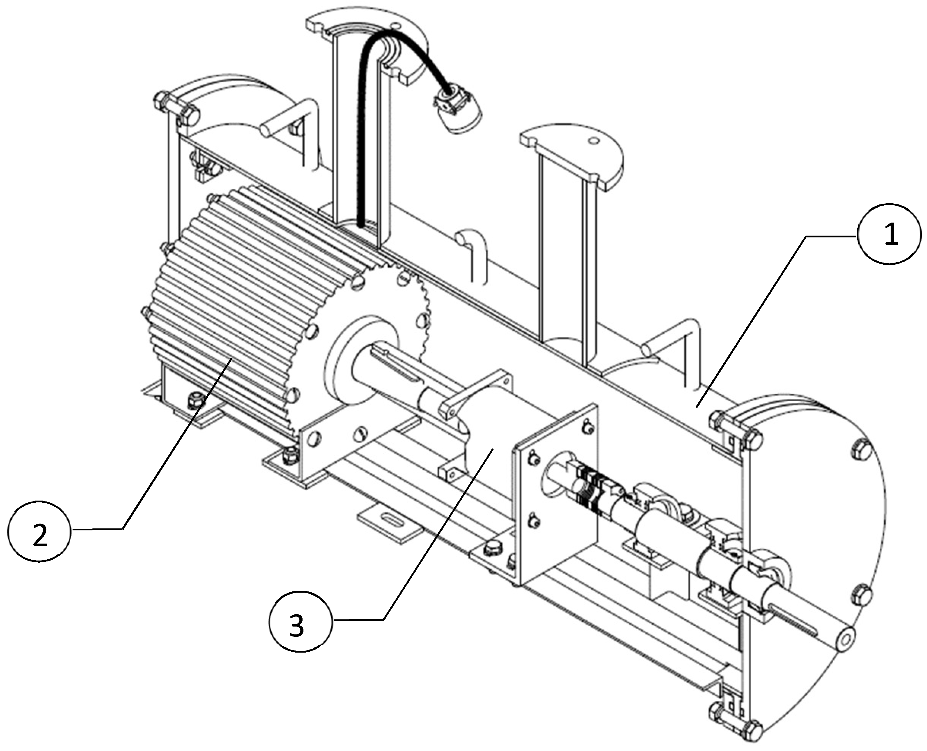
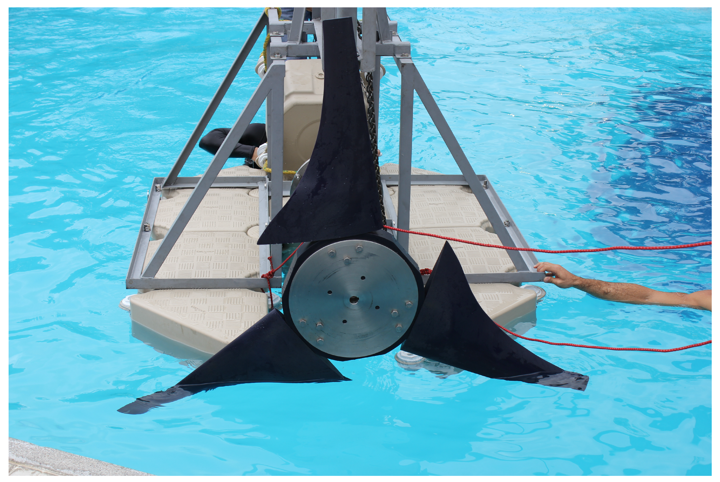
3.2. Hydrokinetic Turbine Manufacturing
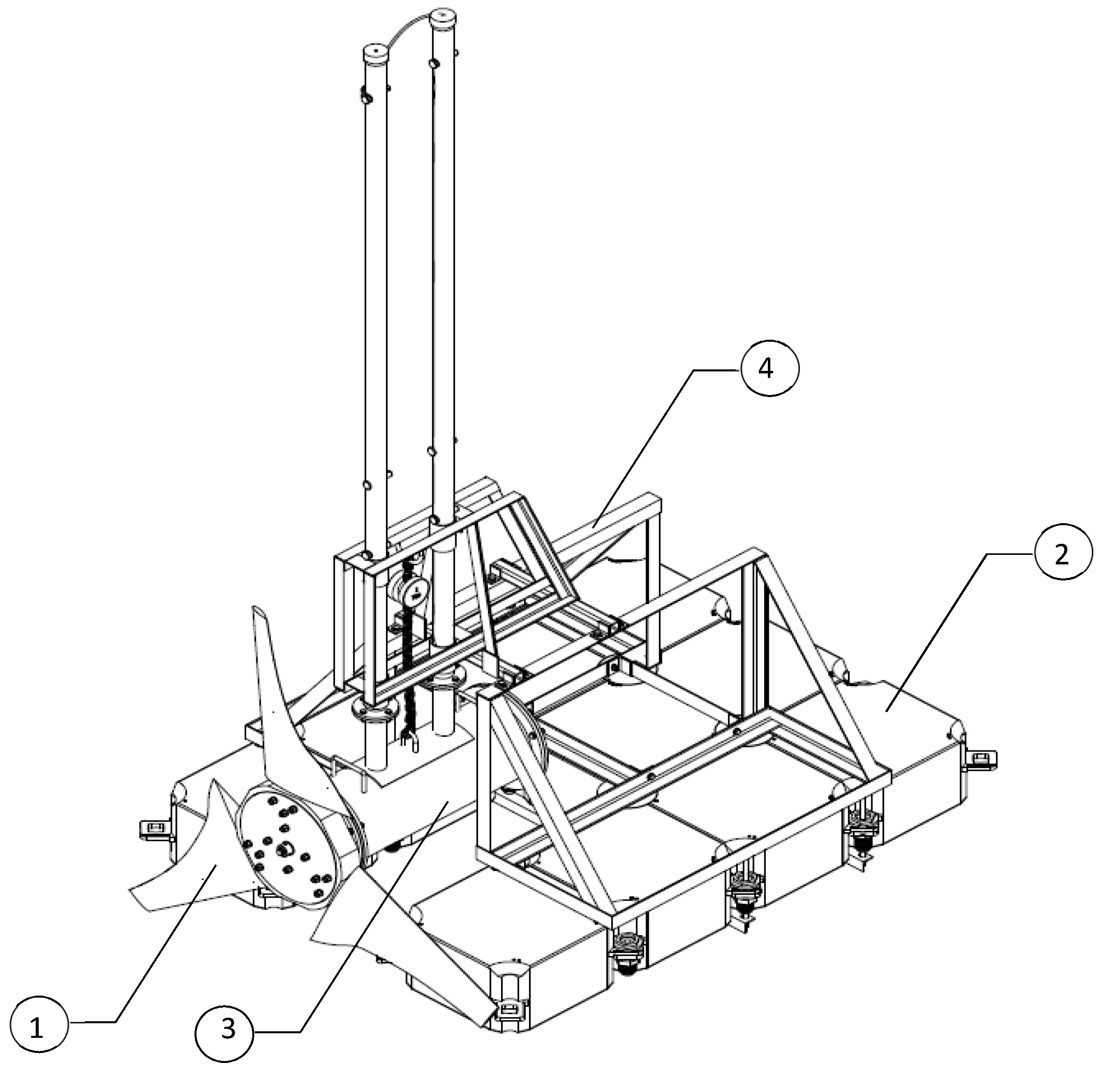
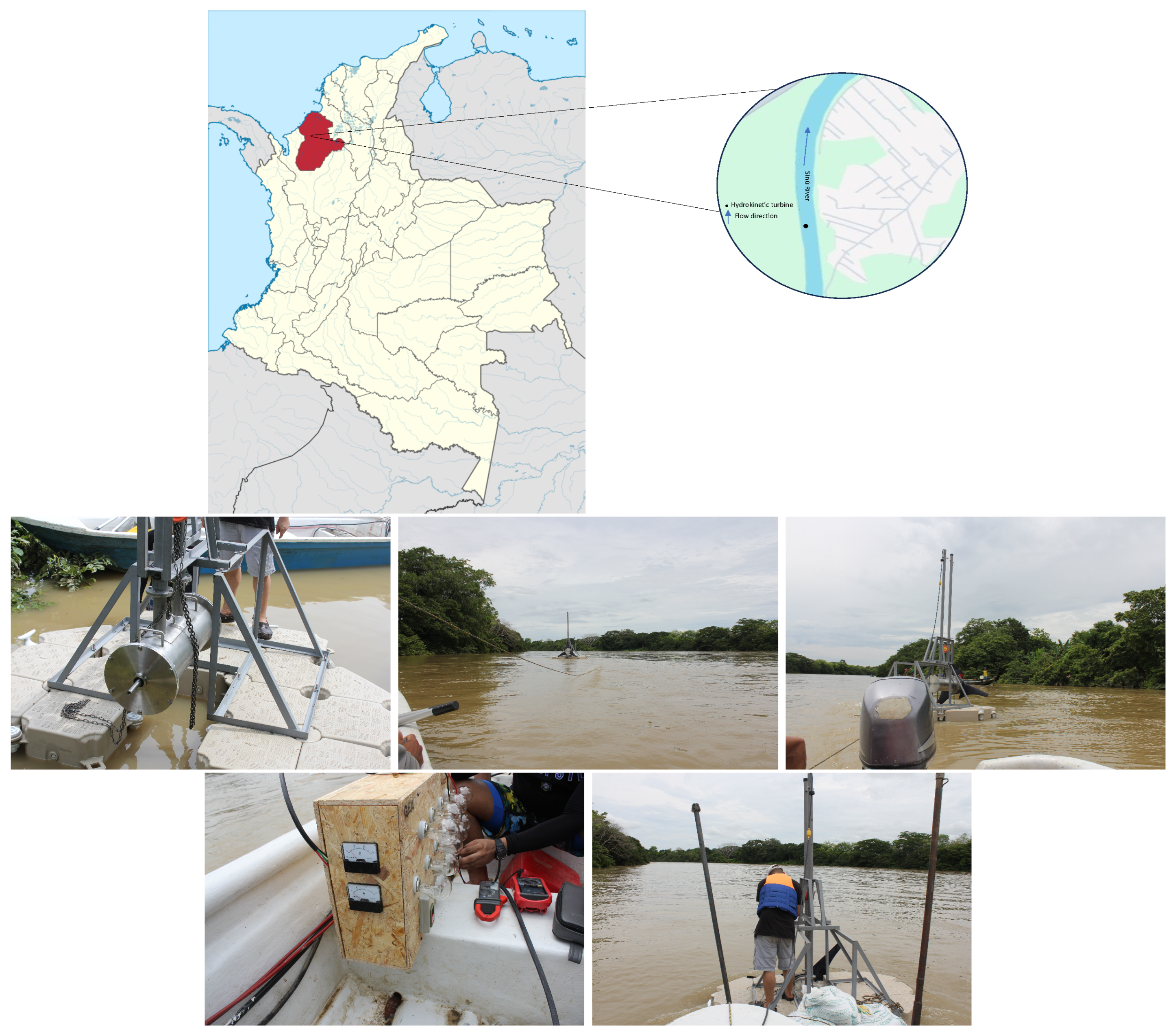
3.3. Experimental Setup
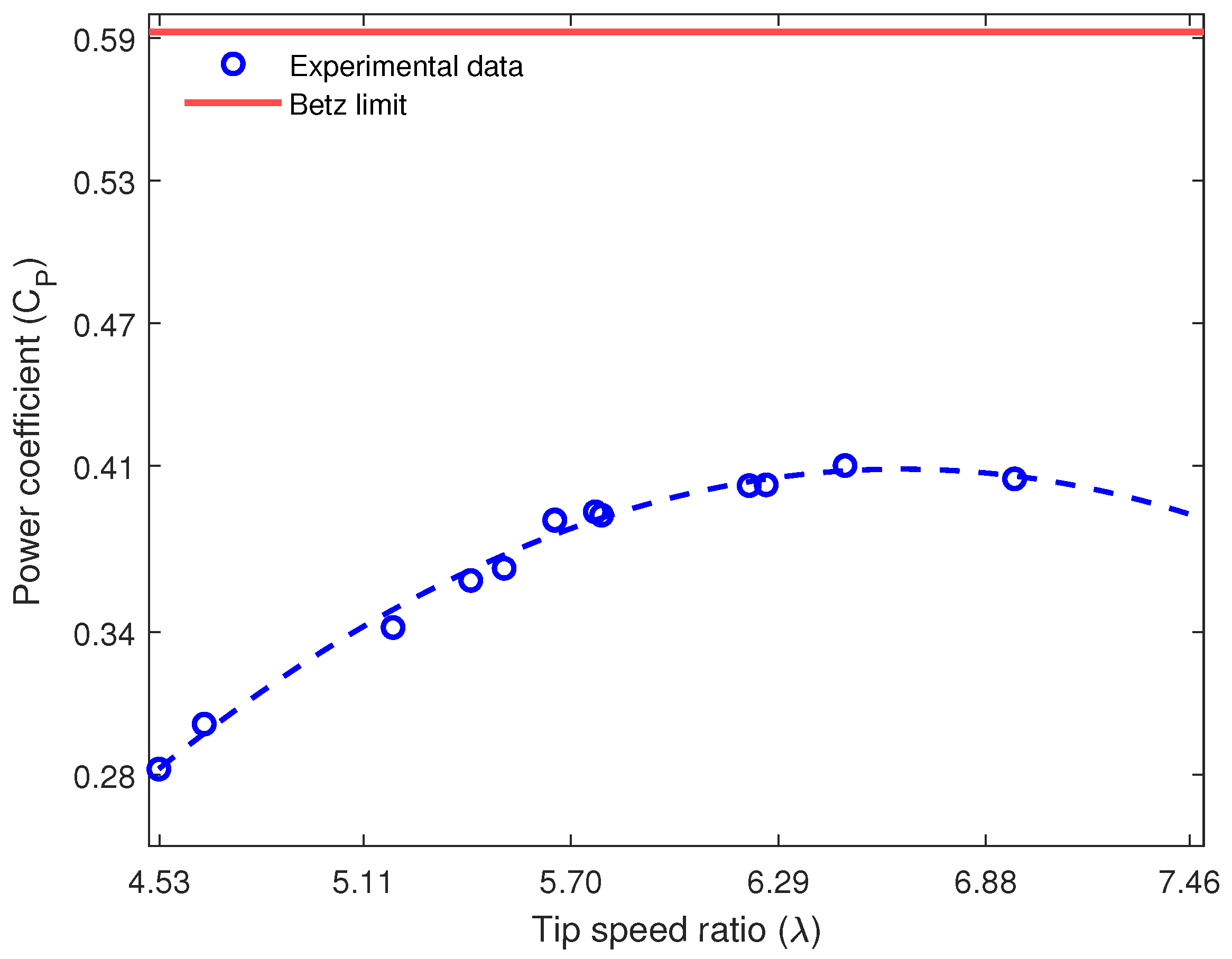
4. Results and Discussion
5. Conclusions
Author Contributions
Funding
Data Availability Statement
Conflicts of Interest
References
- Holechek, J.L.; Geli, H.M.; Sawalhah, M.N.; Valdez, R. A global assessment: Can renewable energy replace fossil fuels by 2050? Sustainability 2022, 14, 4792. [Google Scholar] [CrossRef]
- Sharma, A. Current Trends and Future Directions in Renewable Energy Systems. Int. J. Res. Publ. Semin. 2024, 15, 186–198. [Google Scholar]
- Wang, J.; Azam, W. Natural resource scarcity, fossil fuel energy consumption, and total greenhouse gas emissions in top emitting countries. Geosci. Front. 2024, 15, 101757. [Google Scholar] [CrossRef]
- Gayen, D.; Chatterjee, R.; Roy, S. A review on environmental impacts of renewable energy for sustainable development. Int. J. Environ. Sci. Technol. 2024, 21, 5285–5310. [Google Scholar] [CrossRef]
- Adams, S.; Klobodu, E.; Apio, A. Renewable and non-renewable energy, regime type and economic growth. Renew. Energy 2018, 125, 755–767. [Google Scholar] [CrossRef]
- Guo, S.; Liu, Q.; Sun, J.; Jin, H. A review on the utilization of hybrid renewable energy. Renew. Sustain. Energy Rev. 2018, 91, 1121–1147. [Google Scholar] [CrossRef]
- Jenniches, S. Assessing the regional economic impacts of renewable energy sources—A literature review. Renew. Sustain. Energy Rev. 2018, 93, 35–51. [Google Scholar] [CrossRef]
- Widyawan, H.; Satrio, D.; Mukhtasor. Numerical Investigation of Vertical-Axis Hydrokinetic Turbine on Side-by-Side Configuration. J. Physics Conf. Ser. 2024, 2828, 012027. [Google Scholar] [CrossRef]
- Romero-Menco, F.; Betancour, J.; Velásquez, L.; Rubio-Clemente, A.; Chica, E. Horizontal-axis propeller hydrokinetic turbine optimization by using the response surface methodology: Performance effect of rake and skew angles. Ain Shams Eng. J. 2024, 15, 102596. [Google Scholar] [CrossRef]
- Chalaca, A.; Velásquez, L.; Rubio-Clemente, A.; Chica, E. Design and Optimization of a Gorlov-Type Hydrokinetic Turbine Array for Energy Generation Using Response Surface Methodology. Energies 2024, 17, 4870. [Google Scholar] [CrossRef]
- Zdankus, N.; Punys, P.; Zdankus, T. Conversion of lowland river flow kinetic energy. Renew. Sustain. Energy Rev. 2014, 38, 121–130. [Google Scholar]
- Anyi, M.; Kirke, B. Evaluation of small axial flow hydrokinetic turbines for remote communities. Energy Sustain. Dev. 2010, 14, 110–116. [Google Scholar]
- Kumar, D.; Sarkar, S. A review on the technology, performance, design optimization, reliability, techno-economics and environmental impacts of hydrokinetic energy conversion systems. Renew. Sustain. Energy Rev. 2016, 58, 796–813. [Google Scholar]
- Vermaak, H.J.; Kusakana, K.; Koko, S.P. Status of micro-hydrokinetic river technology in rural applications: A review of literature. Renew. Sustain. Energy Rev. 2014, 29, 625–633. [Google Scholar]
- Mabrouki, I.; Driss, Z.; Abid, M.S. Experimental investigation of the height effect of water Savonius rotors. Int. J. Mech. Appl. 2014, 4, 8–12. [Google Scholar]
- Vennell, R. Exceeding the Betz limit with tidal turbines. Renew. Energy 2013, 55, 277–285. [Google Scholar] [CrossRef]
- Zhang, D.; Guo, P.; Cheng, Y.; Hu, Q.; Li, J. Analysis of blockage correction methods for high-solidity hydrokinetic turbines: Experimental and numerical investigations. Ocean Eng. 2023, 283, 115185. [Google Scholar]
- Kusakana, K.; Vermaak, H.J. Hydrokinetic power generation for rural electricity supply: Case of South Africa. Renew. Energy 2013, 55, 467–473. [Google Scholar]
- Khan, M.J.; Bhuyan, G.; Iqbal, M.T.; Quaicoe, J.E. Hydrokinetic energy conversion systems and assessment of horizontal and vertical axis turbines for river and tidal applications: A technology status review. Appl. Energy 2009, 86, 1823–1835. [Google Scholar]
- Khan, M.; Islam, N.; Iqbal, T.; Hinchey, M.; Masek, V. Performance of Savonius rotor as a water current turbine. J. Ocean Technol. 2009, 4, 71–83. [Google Scholar]
- Chica, E.; Pérez, F.; Rubio-Clemente, A. Influence of the diffusor angle and a damper opening angle on the performance of a hydrokinetic turbine. Environ. Prog. Sustain. Energy 2018, 37, 824–831. [Google Scholar]
- Manwell, J.; McGowan, J.; Rogers, A. Aerodynamics of Wind Turbines, 2nd ed.; John Wiley & Sons: London, UK, 2009; pp. 23–155. [Google Scholar]
- Hall, C.; Dixon, S.L. Fluid Mechanics and Thermodynamics of Turbomachinery; Butterworth-Heinemann: Oxford, UK, 2013. [Google Scholar]
- Punys, P.; Adamonyte, I.; Kvaraciejus, A.; Martinaitis, E.; Vyciene, G.; Kasiulis, E. Riverine hydrokinetic resource assessment. A case study of a lowland river in Lithuania. Renew. Sustain. Energy Rev. 2015, 50, 643–652. [Google Scholar]
- da Silva Holanda, P.; Blanco, C.J.C.; Mesquita, A.L.A.; Junior, A.C.P.B.; de Figueiredo, N.M.; Macêdo, E.N.; Secretan, Y. Assessment of hydrokinetic energy resources downstream of hydropower plants. Renew. Energy 2017, 101, 1203–1214. [Google Scholar]
- ULC; VPC. Technology Evaluation of Existing and Emerging Technologies—Water Current Turbines for River Applications; Technical Report; Natural Resources Canada: Ottawa, ON, Canada, 2006. [Google Scholar]
- Johnson, J.; Toniolo, H.; Seitz, A.; Schmid, J.; Duvoy, P. Characterization of the Tanana River at Nenana, Alaska, to Determine the Important Factors Affecting Site Selection, Deployment, and Operation of Hydrokinetic Devices to Generate Power; The Alaska Center for Energy and Power, Alaska Hydrokinetic Energy Research Center: Fairbanks, AK, USA, 2013; Volume 130. [Google Scholar]
- Dhanak, M.R.; Duerr, A.E.; VanZwieten, J.H. Marine Hydrokinetic Energy Resource Assessment. In Springer Handbook of Ocean Engineering; Dhanak, M.R., Xiros, N.I., Eds.; Springer: Cham, Switzerland, 2016. [Google Scholar]
- Ruprecht, A.; Bauer, N.; Oakley, M. Development of a hydrokinetic turbine for decentralized electricity production in developing countries. In Proceedings of the Hidroenergia 2012: The International Congress and Exhibition on Small Hydropower, Wroclaw, Poland, 23–26 May 2012; pp. 23–26. [Google Scholar]
- Ramírez, R.D.M.; Cuervo, F.I.; Rico, C.A.M. Technical and financial valuation of hydrokinetic power in the discharge channels of large hydropower plants in Colombia: A case study. Renew. Energy 2016, 99, 136–147. [Google Scholar]
- Nago, V.G.; dos Santos, I.F.S.; Gbedjinou, M.J.; Mensah, J.H.R.; Tiago Filho, G.L.; Camacho, R.G.R.; Barros, R.M. A literature review on wake dissipation length of hydrokinetic turbines as a guide for turbine array configuration. Ocean Eng. 2022, 259, 111863. [Google Scholar]
- Cacciali, L.; Battisti, L.; Dell’Anna, S. Multi-array design for hydrokinetic turbines in hydropower canals. Energies 2023, 16, 2279. [Google Scholar] [CrossRef]
- Nunes, M.M.; Mendes, R.C.; Oliveira, T.F.; Junior, A.C.B. An experimental study on the diffuser-enhanced propeller hydrokinetic turbines. Renew. Energy 2018, 133, 840–848. [Google Scholar]
- Tian, W.; Mao, Z.; Ding, H. Design, test and numerical simulation of a low-speed horizontal axis hydrokinetic turbine. Int. J. Nav. Archit. Ocean Eng. 2018, 10, 782–793. [Google Scholar]
- Laws, N.D.; Epps, B.P. Hydrokinetic energy conversion: Technology, research, and outlook. Renew. Sustain. Energy Rev. 2016, 57, 1245–1259. [Google Scholar]
- Anyi, M.; Kirke, B. Hydrokinetic turbine blades: Design and local construction techniques for remote communities. Energy Sustain. Dev. 2011, 15, 223–230. [Google Scholar]
- Güney, M.S.; Kaygusuz, K. Hydrokinetic energy conversion systems: A technology status review. Renew. Sustain. Energy Rev. 2010, 14, 2996–3004. [Google Scholar] [CrossRef]
- Ismail, K.A.; Batalha, T.P. A comparative study on river hydrokinetic turbine blade profiles. J. Eng. Res. Appl. 2015, 5, 1–10. [Google Scholar]
- van Els, R.H.; Junior, A.C.P.B. The Brazilian experience with hydrokinetic turbines. Energy Procedia 2015, 75, 259–264. [Google Scholar] [CrossRef]
- Muñoz, A.H.; Chiang, L.E.; De la Jara, E.A. A design tool and fabrication guidelines for small low cost horizontal axis hydrokinetic turbines. Energy Sustain. Dev. 2014, 22, 21–33. [Google Scholar] [CrossRef]
- Lata-García, J.; Jurado, F.; Fernández-Ramírez, L.M.; Sánchez-Sainz, H. Optimal hydrokinetic turbine location and techno-economic analysis of a hybrid system based on photovoltaic/hydrokinetic/hydrogen/battery. Energy 2018, 159, 611–620. [Google Scholar]
- John, B.; Varghese, J. Sizing and techno-economic analysis of hydrokinetic turbine based standalone hybrid energy systems. Energy 2021, 221, 119717. [Google Scholar] [CrossRef]
- Schramm, M.P.; Bevelhimer, M.; Scherelis, C. Effects of hydrokinetic turbine sound on the behavior of four species of fish within an experimental mesocosm. Fish. Res. 2017, 190, 1–14. [Google Scholar]
- Gómez-Navarro, T.; Ribó-Pérez, D. Assessing the obstacles to the participation of renewable energy sources in the electricity market of Colombia. Renew. Sustain. Energy Rev. 2018, 90, 131–141. [Google Scholar]
- Balibar, S. Energy transitions after COP21 and 22. Comptes Rendus Phys. 2017, 18, 479–487. [Google Scholar] [CrossRef]
- Rosso-Cerón, A.M.; Kafarov, V. Barriers to social acceptance of renewable energy systems in Colombia. Curr. Opin. Chem. Eng. 2015, 10, 103–110. [Google Scholar] [CrossRef]
- Morales, S.; Álvarez, C.; Acevedo, C.; Diaz, C.; Rodriguez, M.; Pacheco, L. An overview of small hydropower plants in Colombia: Status, potential, barriers and perspectives. Renew. Sustain. Energy Rev. 2015, 50, 1650–1657. [Google Scholar]
- Chica, E.; Pérez, F.; Rubio-Clemente, A.; Agudelo, S. Design of a hydrokinetic turbine. WIT Trans. Ecol. Env. 2015, 195, 137–148. [Google Scholar]
- Chica, E.; Pérez, F.; Rubio-Clemente, A. Rotor structural design of a hydrokinetic turbine. Int. J. Appl. Eng. Res. 2016, 11, 2890–2897. [Google Scholar]
- Chica, E.; Rubio-Clemente, A. Design of Zero Head Turbines for Power Generation. In Renewable Hydropower Technologies; InTech: Rijeka, Croatia, 2017. [Google Scholar]
- Prasad, C.; Soren, R. Simulation of flow over double-element airfoil and wind tunnel test for use in vertical axis wind turbine. J. Physics Conf. Ser. 2014, 524, 012009. [Google Scholar]
- Giguere, P.; Selig, M. Low Reynolds number airfoils for small horizontal axis wind turbines. Wind Eng. 1997, 21, 367–380. [Google Scholar]
- Ronit, K.; Singh, M.; Rafiuddin Ahmed, M.; Zullah, M.; Lee, Y.H. Design of a low Reynolds number airfoil for small horizontal axis wind turbines. Renew. Energy 2012, 42, 66–76. [Google Scholar]
- Jai, N.; Goundar, M.; Rafiuddin, A.; Lee, Y.H. Numerical and experimental studies on hydrofoils for marine current turbines. Renew. Energy 2012, 42, 173–179. [Google Scholar]
- Oller, S.; Nallim, L. The usability of the Selig S1223 profile airfoil as a high lift hydrofoil for hydrokinetic application. J. Appl. Fluid Mech. (JAFM) 2016, 9, 534–542. [Google Scholar]
- Hepperle, M. JAVAFOIL Users Guide. 2018. Available online: https://www.mh-aerotools.de/airfoils/java/JavaFoil%20Users%20Guide.pdf (accessed on 22 October 2018).
- Andreadis, K.M.; Schumann, G.J.P.; Pavelsky, T. A simple global river bankfull width and depth database. Water Resour. Res. 2013, 49, 7164–7168. [Google Scholar] [CrossRef]
- Kirke, B. Hydrokinetic and ultra-low head turbines in rivers: A reality check. Energy Sustain. Dev. 2019, 52, 1–10. [Google Scholar]
- Slootweg, J.; Polinder, H.; Kling, W. Dynamic modelling of a wind turbine with doubly fed induction generator. In Proceedings of the Power Engineering Society Summer Meeting, Vancouver, BC, Canada, 15–19 July 2001; Volume 1, pp. 644–649. [Google Scholar]
- Yavuz, T.; Koç, E.; Kılkış, B.; Erol, Ö.; Balas, C.; Aydemir, T. Performce analysis of the airfoil-slat arrangements for hydro and wind turbine applications. Renew. Energy 2015, 74, 414–421. [Google Scholar]
- Mycek, P.; Gaurier, B.; Germain, G.; Pinon, G.; Rivoalen, E. Experimental study of the turbulence intensity effects on marine current turbines behaviour. Part I: One single turbine. Renew. Energy 2014, 66, 729–746. [Google Scholar]
- Mycek, P.; Gaurier, B.; Germain, G.; Pinon, G.; Rivoalen, E. Experimental study of the turbulence intensity effects on marine current turbines behaviour. Part II: Two interacting turbines. Renew. Energy 2014, 68, 876–892. [Google Scholar]
- Bahaj, A.; Molland, A.; Chaplin, J.; Batten, W. Power and thrust measurements of marine current turbines under various hydrodynamic flow conditions in a cavitation tunnel and a towing tank. Renew. Energy 2007, 32, 407–426. [Google Scholar]
- Jeffcoate, P.; Whittaker, T.; Boake, C.; Elsaesser, B. Field tests of multiple 1/10 scale tidal turbines in steady flows. Renew. Energy 2016, 87, 240–252. [Google Scholar]
- Atcheson, M.; MacKinnon, P.; Elsaesser, B. A large scale model experimental study of a tidal turbine in uniform steady flow. Ocean Eng. 2015, 110, 51–61. [Google Scholar]
- Morandi, B.; Di Felice, F.; Costanzo, M.; Romano, G.; Dhomé, D.; Allo, J. Experimental investigation of the near wake of a horizontal axis tidal current turbine. Int. J. Mar. Energy 2016, 14, 229–247. [Google Scholar]
- Seo, J.; Lee, S.J.; Choi, W.S.; Park, S.T.; Rhee, S.H. Experimental study on kinetic energy conversion of horizontal axis tidal stream turbine. Renew. Energy 2016, 97, 784–797. [Google Scholar]
- Doman, D.A.; Murray, R.E.; Pegg, M.J.; Gracie, K.; Johnstone, C.M.; Nevalainen, T. Tow-tank testing of a 1/20th scale horizontal axis tidal turbine with uncertainty analysis. Int. J. Mar. Energy 2015, 11, 105–119. [Google Scholar]
- Aguilar, J.; Velásquez, L.; Romero, F.; Betancour, J.; Rubio-Clemente, A.; Chica, E. Numerical and experimental study of hydrofoil-flap arrangements for hydrokinetic turbine applications. J. King Saud Univ.-Eng. Sci. 2023, 35, 577–588. [Google Scholar]
- Hagerman, G.; Polagye, B.; Bedard, R.; Previsic, M. Methodology for Estimating Tidal Current Energy Resources and Power Production by Tidal In-Stream Energy Conversion (TISEC) Devices; EPRI North American Tidal In Stream Power Feasibility Demonstration Project; Electric Power Research Institute (EPRI): Palo Alto, CA, USA, 2006; Volume 1. [Google Scholar]
- Previsic, M.; Bedard, R. System Level Design, Performance, Cost and Economic Assessment—San Francisco Tidal In-Stream Power Plant; Technical Report; Electric Power Research Institute (EPRI): Palo Alto, CA, USA, 2006. [Google Scholar]
- Tangler, J.L.; Somers, D.M. NREL Airfoil Families for HAWTs; Technical Report NREL/TP-442-7109; National Renewable Energy Lab.: Golden, CO, USA, 1995. [Google Scholar]
- Chica, E.; Torres, E.; Arbeláez, J. Manufacture and experimental evaluation of a hydrokinetic turbine for remote communities in Colombia. In Proceedings of the International Conference on Renewable Energies and Power Quality (ICREPQ’18), Salamanca, Spain, 21–23 March 2018; pp. 1–12. [Google Scholar]


| Reference | Test Facility (m) | Rotor Diameter (m/s) | Flow Velocity | TSR | |
|---|---|---|---|---|---|
| [66] | Water channel | 0.402 | 2.76 | 2.60 | 0.390 |
| [64] | Field test | 1.500 | 1.00 | 3.00 | 0.340 |
| [63] | Water channel | 0.800 | 1.73 | 6.00 | 0.460 |
| [67] | Towing tank | 0.400 | 1.436 | 3.50 | 0.278 |
| [68] | Towing tank | 0.762 | 1.00 | 3.53 | 0.285 |
| [61,62] | Towing tank | 0.700 | 1.20 | 4.80 | 0.440 |
| [60] | Towing tank | 1.200 | 2.00 | 5.51 | 0.470 |
| [65] | Field test | 1.500 | 1.10 | 3.10 | 0.330 |
| [34] | Towing tank | 1.200 | 0.50 | 5.37 | 0.330 |
| [69] | Numerical result | 1.580 | 1.50 | 6.739 | 0.419 |
| [69] | Water channel | 0.120 | 0.56 | 6.48 | 0.394 |
| Parameter | Value |
|---|---|
| Diameter (D) | 1.58 m |
| Number of blades | 3 |
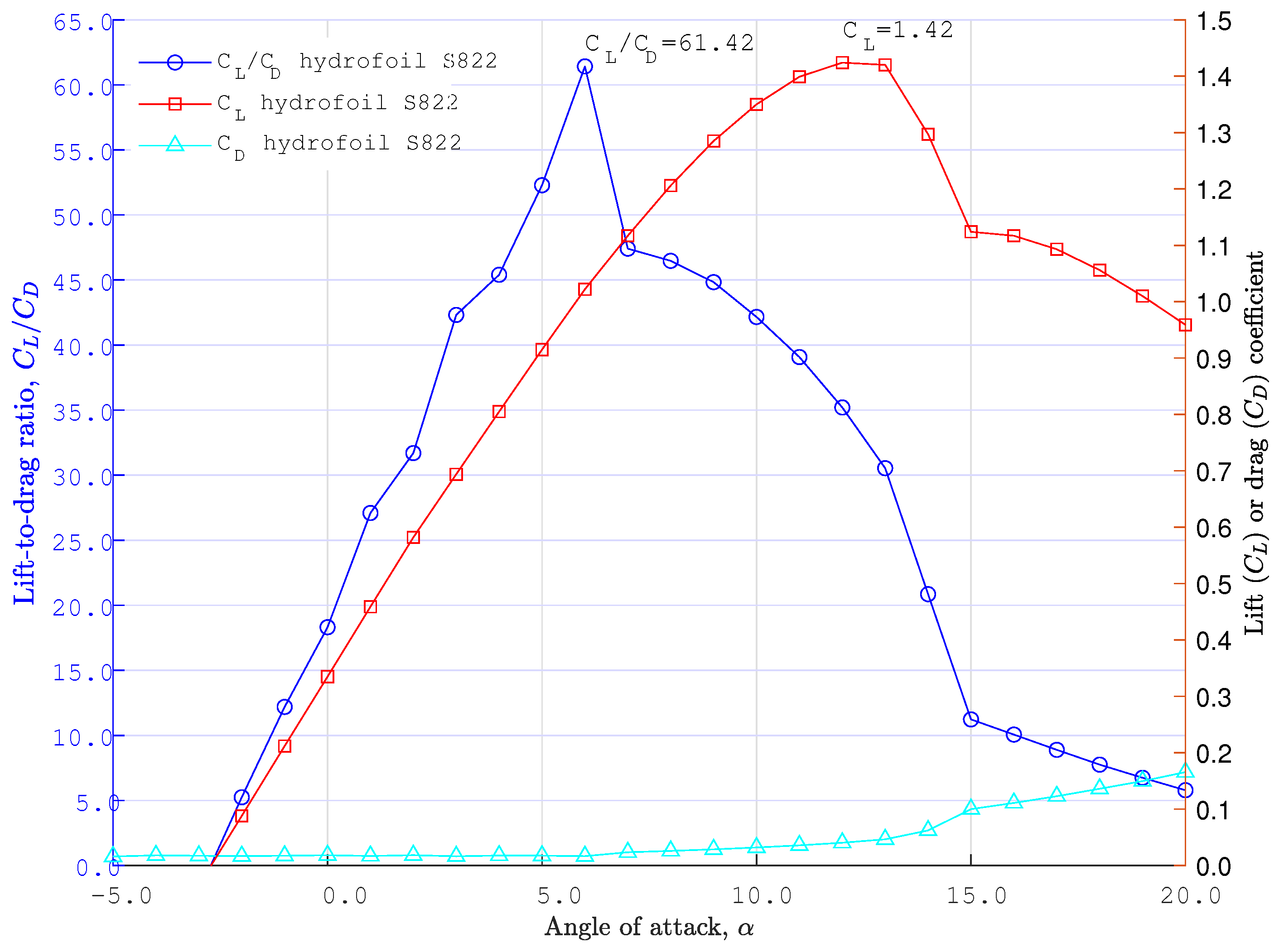
| Hydrofoil | S822 |
| Angle of attack () | 5° |
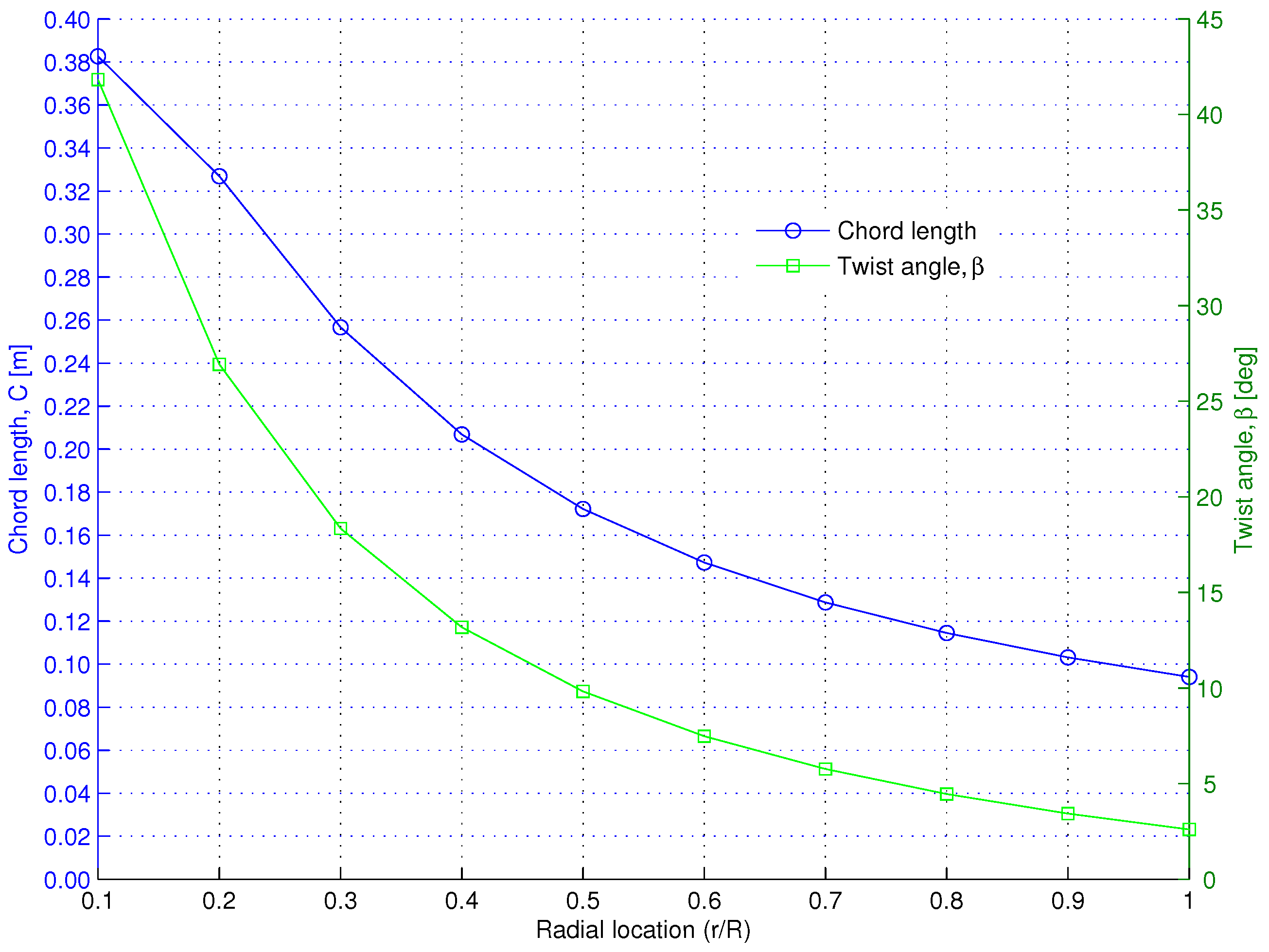
| Twist angle () | Depend of radial location |
| Chord length (C) | Depend on radial location |
Disclaimer/Publisher’s Note: The statements, opinions and data contained in all publications are solely those of the individual author(s) and contributor(s) and not of MDPI and/or the editor(s). MDPI and/or the editor(s) disclaim responsibility for any injury to people or property resulting from any ideas, methods, instructions or products referred to in the content. |
© 2025 by the authors. Licensee MDPI, Basel, Switzerland. This article is an open access article distributed under the terms and conditions of the Creative Commons Attribution (CC BY) license (https://creativecommons.org/licenses/by/4.0/).
Share and Cite
Chica, E.; Velásquez, L.; Rubio-Clemente, A. Full-Scale Experimental Assessment of a Horizontal-Axis Hydrokinetic Turbine for River Applications: A Challenge for Developing Countries. Energies 2025, 18, 1657. https://doi.org/10.3390/en18071657
Chica E, Velásquez L, Rubio-Clemente A. Full-Scale Experimental Assessment of a Horizontal-Axis Hydrokinetic Turbine for River Applications: A Challenge for Developing Countries. Energies. 2025; 18(7):1657. https://doi.org/10.3390/en18071657
Chicago/Turabian StyleChica, Edwin, Laura Velásquez, and Ainhoa Rubio-Clemente. 2025. "Full-Scale Experimental Assessment of a Horizontal-Axis Hydrokinetic Turbine for River Applications: A Challenge for Developing Countries" Energies 18, no. 7: 1657. https://doi.org/10.3390/en18071657
APA StyleChica, E., Velásquez, L., & Rubio-Clemente, A. (2025). Full-Scale Experimental Assessment of a Horizontal-Axis Hydrokinetic Turbine for River Applications: A Challenge for Developing Countries. Energies, 18(7), 1657. https://doi.org/10.3390/en18071657