Article

Experimental Studies on the Critical Reynolds Number in the Flow of a Microencapsulated Phase Change Material Slurry

Department of Mechanical and Power Engineering, Koszalin University of Technology, 75-453 Koszalin, Poland
*
Author to whom correspondence should be addressed.
Energies 2025, 18(6), 1520; https://doi.org/10.3390/en18061520
Submission received: 25 February 2025 / Revised: 6 March 2025 / Accepted: 17 March 2025 / Published: 19 March 2025

Abstract

:
The disadvantage of phase change materials (PCMs) that store thermal energy is their low thermal conductivity. The macro-, micro-, and nanoencapsulation of PCMs are some of the ways to eliminate this drawback. Liquids with micro- and nanometer-sized capsules containing PCMs have become innovative working fluids for heat transfer—a slurry of encapsulated PCMs. This paper shows the results of in-depth studies on the nature of fluid movement (slurry of microencapsulated PCMs) in pipe channels. The slurry flowed inside a tube with a diameter of 4 mm in the range of Re = 350–11,000. The PCM microcapsule (mPCM) concentration ranged from 4.30% to 17.2%. A pressure loss measurement was carried out on a section of 400 mm. The temperature of the flowing slurry was selected so that the PCMs in the microcapsules were in a liquid state and were solid during subsequent measurement series after undergoing a phase transformation. It was found that the boundary of the transition from laminar to turbulent flow is influenced by both the mPCM concentration in the slurry and the state of matter of the PCMs in the microcapsules. The influence of the slurry concentration and the state of matter of the PCMs in the microcapsules on changes such as fluid movement is presented (in terms of the critical Reynolds number).

1. Introduction

One of the problems that humanity must face is the reduction in substances that contribute to global warming. For this reason, one of the EU’s pro-ecological policy goals is reducing greenhouse gases released into the atmosphere [1]. This goal can be achieved by introducing an energy economy based on, for example, storing various forms of energy. Thermal energy storage, especially using substances with high heat capacity, has become attractive in basic and applied research [2]. The use of phase change materials (PCMs) for thermal energy storage meets the expectations for thermal energy storage, as it allows for the storage of significant amounts of energy per unit of mass of the substance (high energy storage density). In contrast, this material undergoes an almost isothermal process of changing its state of matter [3]. Selected organic and inorganic substances and combinations of the two previous types of substances—eutectic mixtures—are used as phase change materials [4]. Paraffin is considered the most suitable organic material for use in low-temperature (<200 °C) thermal energy storage [4]. Its primary disadvantage, which hinders the transfer of thermal energy, is the low value of the thermal conductivity coefficient. Typically, it ranges from 0.1 W/(m·K) up to 0.4 W/(m·K) [5]. Several solutions make it possible to improve the thermal conduction coefficient of PCMs. One way is to add a material with a high thermal conductivity coefficient to the PCM (graphene, metal nanoparticles [6], metallic porous structure [7]). Another way is to improve the proportion of the contact area of the PCM and the thermal energy carrier to the volume unit of the TES. One way to increase this proportion is to use fins on the heat exchange surface [8] or to grind the PCM and enclose it in separate containers [9]. Encapsulation, on the one hand, promotes the initiation of the PCM phase transformation process in each volume, and on the other hand, it prevents leaks and changes in the volume of the substance as its state changes. Encapsulation methods can be divided into macro-, micro-, and nanoencapsulation [10]. PCM microencapsulation (mPCM) is a process in which a thin polymer layer surrounds the PCMs and the capsule size ranges from 0.1 µm to 1000 µm [11]. The mPCM slurry is a new type of latent functionally thermal fluid, an alternative to ice slurry or PCM emulsion [12]. Numerous studies were conducted to determine the basic properties of mPCM slurry as an innovative fluid that could be used in heat exchange systems. Among others, the viscosity [13,14,15,16], density [17,18,19,20], specific heat [21,22,23], thermal conductivity coefficient [24,25,26], and temperature and phase transformation enthalpy [27,28,29] of the new mPCM slurry were studied. In this context, the number of publications devoted to research on thermal flow parameters obtained during the mPCM slurry flow through elements of thermal circuit installations seems to be significantly limited.

2. Literature Review

Alvarado et al. [30], Taherian et al. [31], Chen et al. [32], and Zhang et al. [33,34] determined the pressure loss caused by the aqueous microencapsulated PCM slurry flow inside straight pipe sections of a constant diameter. It was found that the flow resistance, in addition to the flow rate, was significantly influenced by the concentration of PCM microcapsules in the slurry. The limited experimental data presented in these publications do not allow for determining the type of fluid flow, i.e., the limit of shifting from laminar flow to turbulent flow.
Wu et al. [35] published data on the flow resistance of mPCM through a heat exchanger with microchannels with dimensions of 25 × 500 × 1000 [µm] and 100 × 500 × 1000 [µm]. A slurry based on synthetic oil and microcapsules with a concentration of 9% and 30% flowed turbulently inside the mini-channels of the exchanger. It was found that the pressure drop in the slurry flow increased with the mPCM concentration and the hydraulic diameter of the microchannels decreased. Comparable conclusions were drawn from the CFD simulation results presented in the work by Ashagre et al. [36], where flow resistance and heat transfer were analyzed during the turbulent flow of mPCM slurry (mPCM concentration from 5% to 30%) in a pipe-in-pipe heat exchanger.
Subsequent works focused on the influence of the mPCM concentration on the pressure drop in the slurry flow in the circulation of solar collectors [37], PV/T panels [38], and radiators based on mini-channels [39], as well as inside stainless steel tubes [40] and divergent channels [41,42]. The results of the applied tests confirmed that an increase in the concentration of the PCMs encapsulated in the slurry increases the flow resistance. However, no data have enabled the determination of the limit at which the nature of the mPCM slurry flow changes.
Inaba et al. [43] presented the results of tests in which shells with tetradecane flowed through a tube of length L = 1000 mm. The mPCM slurry with a concentration ranging from 10.2% to 40.8% flowed turbulently inside a tube with an internal diameter of d = 16 mm. The temperature of the slurry during the experiments was T = 278.1 K (solid PCMs) and T = 288.1 K (liquid PCMs). It was found that temperature (the state of matter of the PCMs) had no influence on the value of slurry flow resistance.
Yamagishi et al. [44] described the results of thermal and flow tests using a slurry of two types of paraffin: n-tetradecane with a phase change temperature t = 5.5 °C and n-dodecane with a phase change temperature t = −13.5 °C. The volume fraction of the microcapsules in the base liquid was 7.3%, 19.1%, and 29.4%. The slurry flowed through a pipe with di = 10 mm and L = 800 mm. The authors showed that the change in the nature of the movement of the slurry fluid took place analogously to that of the fluid without the addition of mPCM, i.e., in the range of Re = 2000–3000.
Yamagishi et al.’s study [45] presented the data from testing the flow of a slurry in which PCM microcapsules of 2–10 μm were added (in amounts from 7% to 30%) to water. The mPCMS flowed through a pipe with di = 10.1 mm and L = 1050 mm. The slurry flow varied from 4.0 L/min to 7.5 L/min, which covered the laminar and turbulent flow range. The change in the nature of fluid motion took place when the Reynolds number was in the range of 2000 to 3000.
A study conducted by Yamagishi et al. [46] described data on the flow resistance of an aqueous slurry composed of a mixture of PCM microcapsules of two different sizes (1.5 µm and 17 µm). The mass fraction of smaller microcapsules in the slurry was constant and amounted to 20%, while the larger ones varied from 10% to 50% of the mass of smaller microcapsules. The slurry flowed through a pipe with di = 16 mm and L = 5.85 m. The obtained characteristics of the friction coefficient from Re show that the fluid movement change occurred after exceeding Re = 2000. The smaller the share of large microcapsules in the slurry, the longer the laminar flow could be maintained (up to a higher Reynolds number).
Rao et al. [47] performed thermal and flow tests on an aqueous mPCM slurry. An mPCM (n-octadecane) slurry composed of microcapsules (2 × 4.2 × 150 [mm]), µm in size, flowed through a mini-channel with a square cross-section of ~5 µm. The mPCM mass fraction in the slurry ranged from 5% to 20%. The slurry flowed in the range of Re = 200–3000. The transition to turbulent flow occurred after reaching Re = 2000. Flow tests showed that only 5% mPCM slurry acted like a Newtonian fluid (the law of laminar fluid motion could describe the friction coefficient—the law of Hagen–Poiseuille). The slurry flow was also laminar in the remaining cases, but the friction coefficient value was higher than for the Newtonian fluid.
Different conclusions can be drawn from the paper by Wang et al. [48]. The authors describe the results of flow tests of an aqueous mPCM slurry with a concentration ranging from 5% to 27.6% by weight. The slurry at a temperature t = 20 °C (the PCM in the microcapsule was in a liquid state) flowed through a tube with an internal diameter d = 4 mm and a length L = 1.46 m in the range Re < 3452. When the slurry flow was laminar, which was the case for Re < 1200, the friction coefficient had values lower than those resulting from the Hagen–Poiseuille equation.
The literature analysis shows that as the mPCM concentration increases, the flow resistance of the slurry increases. The few available publications indicate that the critical Reynolds number for the flow of mPCM slurry may have values lower or higher than Re ≈ 2300, which is the classic criterion for the transition from laminar to turbulent flow. There are no detailed test results based on which it would be possible to assess the influence of the concentration of mPCM slurry on the critical Reynolds number. Moreover, there are no publications based on which it would be possible to determine the impact of the state of PCM matter inside the shells on the value of the critical Reynolds number in the flow of the mPCM slurry.
This article describes detailed experimental research data, aiming to determine the influence of the state of matter of PCMs inside the microcapsule and the mPCM concentration on the value of critical Reynolds number at which the nature of the fluid movement (mPCM slurry) changes. Seven samples of aqueous slurry with different masses of mPCM content of 4.30–17.20% were prepared. The mPCMS with a temperature of 7 °C (the PCM in the microcapsules was in the solid state), 24 °C (the PCM in the microcapsules underwent a phase change), and 44 °C (the PCM in the microcapsules was in the liquid state) flowed through a tube with di = 4 mm and L = 400 mm. The entire test was performed in the Re = 350–11,000 range.

3. Experimental Tests

3.1. Slurry of Microencapsulated Phase Change Material

A concentrate of mPCM with marked MICRONAL® 5428 (product of Microtek Labs; Moraine, OH, USA) was used [49]. The concentrate consisted of water (~57%) and microcapsules filled with paraffin wax (43% ± 1%). The microcapsules had a diameter from 1 mm to 5 mm and consisted of paraffin (catalog melting point t = 28 °C ± 1 °C) in a shell made of polymethyl methacrylate polymer. Since the concentrate was characterized by a very high viscosity, which excluded the possibility of its direct use in flow tests, samples were prepared in which the mPCM content in water was 4.30%, 6.45%, 8.60%, 10.75%, 12.09%, 14.24%, and 17.20%, respectively. The phase change material (PCM) microcapsule slurries have phase change temperatures near room temperature, limiting their application range for thermal energy storage but can be used in specific application scenarios, such as for building insulation or heat pump heating, primarily addressing the spatial and temporal imbalance of low-grade thermal energy supply and demand.
The prepared samples were subjected to basic physical tests, including density and viscosity tests. The slurry density used for testing was determined using a procedure presented in [50]. The viscosity of the slurry was measured as described in the authors’ study [51,52]. Examples of measurement results of the density and viscosity of the slurry used in the flow tests are shown in Figure 1 and Figure 2, respectively. Based on the detailed experimental test results obtained, it was found that the phase transformation process of the PCM in the slurry samples differed in value from that indicated by the concentrate manufacturer and occurred in the temperature range from 22 °C to 27 °C. In taking into account the above information, the relevant experimental data were carried out at a temperature of 7 °C (the PCM in the microcapsules was a solid), 24 °C (the PCM in the microcapsules underwent a phase change), and 44 °C (the PCM in the microcapsules was a liquid).

3.2. Experimental Stand

The test stand is shown schematically in Figure 3. It consisted of a compact gear pump forcing the flow of the mPCM slurry, a plate heat exchanger for regulating and stabilizing the slurry temperature reaching the test section, a slurry tank, and a mass flow meter for measuring the mass flow rate of the mPCMS regulated by valves.
The essential element of the experimental stand was the test section. It was a straight copper pipe with L = 900 mm and di = 4 mm. Two holes were drilled into the pipe and arranged in such a way that the entire tube was divided into three sections. The primary section is called the hydrodynamic entrance, and the length of its velocity profile was developed to be 350 mm long. The second zone, with L = 400 mm—a hydrodynamically fully developed region—constituted the actual measurement section. The pressure loss was measured along its length. The third zone, 150 mm long, is the outlet zone enabling unobstructed flow of liquid from the testing section. Along the length of the test section, three thermoelectric thermometers were placed evenly on the outer surface of the tube to measure the temperature of the flowing liquid. The entire research section was thermally insulated.

3.3. The Scope of the Tests and the Methodology

The mPCMS flowed from the liquid tank (Figure 3) through a Coriolis-type mass flow meter. The measuring range of the flowmeter was 0–200 kg/h, and the accuracy was ±0.2% of the measured value. Therefore, the maximum measurement error corresponding to the highest value of the slurry mass flow rate measured during the tests was ±0.22 kg/h. The slurry pumped by a compact gear pump flowed through a control valve, which enabled the flow to be throttled and excess liquid to be directed through the bypass, where there was another control valve. Appropriate valve setting allowed for the smooth regulation and maintenance of a constant mass flow rate through the measuring section. The working liquid flowed to the plate heat exchanger, where it was possible to determine the temperature of the slurry using the liquid circulating in an additional circuit. The experimental value of the slurry temperature, adopted for further analyses, was the mean value of the 3 readings of the thermoelectric thermometers placed under the thermal insulation on the surface of the tube. Type K thermoelectric thermometers were individually marked in the temperature range of 10–60 °C. The temperature measurement accuracy obtained after calibrating thermoelectric thermometers against a glass reference thermometer was ±0.2 °C. The pressure drop was measured using a piezoresistive differential pressure sensor. The device had a class 0.075 measuring range of 0–50 kPa. Hence, the maximum error in the pressure loss measurement was ±37.5 Pa. All measurements concerned the steady-state performance. For each mPCM concentration and slurry flow in the range Re = 350–11,000, flow resistance measurements were carried out, i.e., a pressure drop over a 400 mm length of the test section. The measurements were carried out in a measurement series that differed in slurry temperature (7, 24, 44 °C).

3.4. Data Reduction

The possibility of comparing the research results of different authors is ensured when the obtained data are presented in the form of dimensionless quantities. Therefore, pressure drop measurements will be presented as a function of the Reynolds number, which was calculated using the following relationship:
R e = w · d i ν = ρ · w · d i μ
where di [m] is the internal diameter of the tube, w [m/s] is the average flow velocity of the slurry inside the tube, ρ [kg/m3] is the density of the slurry, and ν [m2/s] and μ [Pa·s] are kinematic and dynamic slurry viscosity coefficients, respectively. Each time, when calculating the Re value, the results of own experimental tests of the properties of the slurries used were used, including density and viscosity measurements, the sample results of which are presented in Figure 1 and Figure 2, respectively. The average slurry flow speed w was calculated from the transformed equation for calculating the mass flow rate [kg/s] in the form
w = m ˙ ρ · A = 4 · m ˙ ρ · π · d 2
where A [m2] is the channel’s cross-sectional area inside the tube. The mass flow rate of slurry was varied during the tests in the range from 5 kg/h to 108.5 kg/h. Depending on the slurry temperature and its flow rate, the value of the Re number changed, and its minimum and maximum values were Remin ≈ 350 and Remax ≈ 11,000.

4. Results and Discussion

Figure 4 shows the results of measuring the pressure drop in the flow of the mPCM slurry with a concentration of 4.30% to 17.20% inside a straight pipe with a length of L = 400 mm and an internal diameter of d = 4 mm. The presented results were obtained during the slurry’s flow at a temperature of 44 °C.
It is noted that as the slurry flow rate increases (increase in Re) the flow resistance increases as well. In the first phase of increasing the Re number, the pressure drop increased so that the characteristic points were arranged along a straight line. This is related to the laminar nature of the slurry flow in the tube. Further increasing the slurry flow rate resulted in a departure from the straight-line characteristic. The change in trend indicates a transition from laminar to turbulent flow. Fully turbulent motion is illustrated by those characteristic points that form a parabola. It can be seen that it is more difficult to maintain the laminar flow along with the increase in concentration of microcapsules, and the transition to fully developed turbulent motion occurs.
From the characteristics presented in Figure 4, the value of the critical Reynolds number is read, i.e., the Re number at which the nature of fluid motion changed (a departure from laminar flow). For the mPCM slurry with a concentration of 4.30%, the critical Reynolds number was Recr ≈ 3100; the Reynolds number was much lower for the slurry with a concentration of 17.2%, which amounted to Recr ≈ 2500. Both values exceed the critical Reynolds number assumed in the engineering assumptions. This may be due to the fact that Recr ≈ 2300 is the lower critical number, meaning that as the flow rate increases, it is theoretically possible to maintain laminar motion well above this value.
The observations known from the literature review were confirmed: the higher the mPCM slurry concentration, the higher the resistance to its flow. However, what is more important is the fact that as the slurry concentration increased, it became increasingly difficult to maintain laminar flow. According to the authors, the microcapsules that were a component of the slurry moved in layers and collided with microcapsules located nearby. In this way, after exceeding a certain flow speed, the microcapsules and liquid particles were thrown off their current path, which prevented further stratified flow of the slurry. The more microcapsules there were, the more frequent the microcapsule collisions were and the lower Re the character of fluid movement changed. It should be emphasized that a similar influence of mPCM concentration on the critical Reynolds number was noted when the tested slurry was at a temperature of 7 and 24 °C.
Figure 5 shows data on the pressure loss results during the flow of the mPCMS with a concentration of 12.09% and temperatures of 7, 24, and 44 °C.
It is noted that when the slurry had a temperature of t = 7 °C (the PCM in the microcapsule was in the solid state), the laminar flow ended at Re < 2000. When the PCM underwent a phase change (t = 24 °C), the transition from laminar to turbulent flow occurred at Re = 2300. The laminar flow of the slurry was maintained for the longest time when the PCM in the microcapsules was liquid (t = 44 °C). The characteristics presented in Figure 5 concern one concentration of microcapsules, but the described phenomenon occurred for each tested slurry concentration. It should be noted that when the PCM was solid, the change in the nature of fluid motion took place below Re = 2300. The microcapsules, together with the PCM, were solid throughout their entire volume. These particles collided with each other and caused the fluid particles to be dislodged from the stratified flow along the channel walls at a much lower Re value than when the PCM in the microcapsules was a liquid. According to the authors, the movement and energy transfer during the collision of liquid-filled capsules is entirely different than in the case of particles that are solid throughout their volume. Liquid PCMs enclosed in a shell caused the microcapsules to dampen the collision energy and the interactions were no longer elastic. As a result, it was possible to maintain the laminar flow of the mPCMS in which PCM was liquid, up to much higher Re values.
Figure 6 presents a summary of the critical Recr number at which the nature of fluid movement changed depending on the concentration and temperature of the mPCM slurry.
It is noticed that regardless of the slurry temperature, it is more difficult to maintain laminar flow. When the PCM in the microcapsules was in the form of a solid, as the slurry concentration increased from 4.30% to 12.9%, the critical Reynolds number decreased, up to the value of Recr ≈ 1600. Further increasing the concentration of the mPCM slurry did not change this value. Each time, the transition from laminar to turbulent motion took place at Recr ≈ 1600. It can be concluded that there is a maximum concentration above which the flow transition limit of a slurry containing PCM in the form of a solid remains unchanged.
An increase in the slurry temperature increased the critical Reynolds number. Similarly to t = 7 °C, the value of the critical Reynolds number decreased with increasing mPCM concentration. There was no maximum mPCM concentration beyond which there would be a “saturation” concentration, beyond which the essential Reynolds number would not depend on the mass fraction of microcapsules in the slurry. Studies with samples with higher concentrations of mPCM in slurry would be required to expand knowledge in this area. It would be interesting to conduct research using PCM microcapsules, in which the shell material would differ from the one used in the study (polymethyl methacrylate polymer). A more rigid coating (e.g., metal) could affect the elastic nature of microcapsule collisions and turbulate the slurry flow, even though the PCM inside would already be a liquid.

5. Conclusions

Based on the research conducted, the following were concluded:
  • Both the concentration of the microcapsules and the state of matter of the PCM inside the shells significantly influenced the critical Reynolds number;
  • The higher the PCM microcapsule concentration in the slurry, the lower the value of the critical Reynolds number;
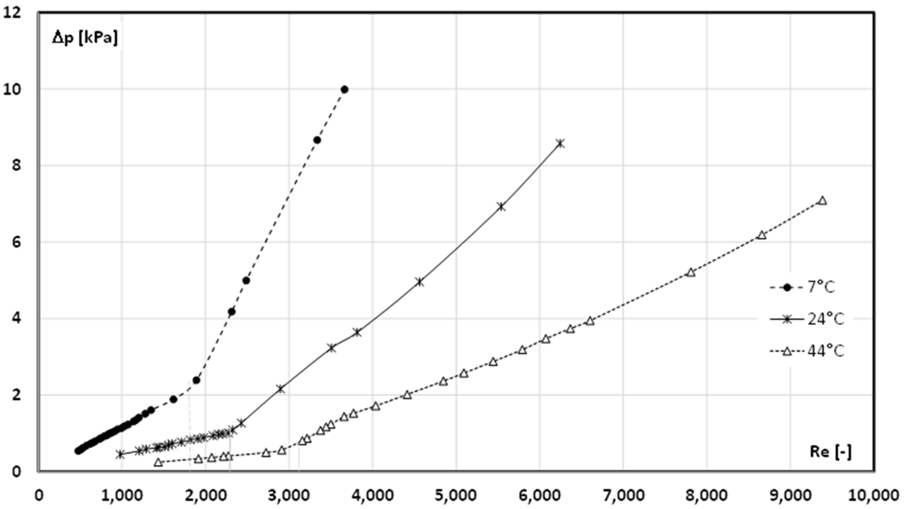
  • The critical Reynolds number for the case when the PCM in the slurry was in the form of a liquid (t = 44 °C) varied from Recr ≈ 3300 (4.30% mPCM) to Recr ≈ 2600 (17.2% mPCM);
  • When the mPCMS temperature was t = 7 °C (the PCM in the microcapsules was in the form of a solid), the critical Reynolds number had much lower values and ranged from Recr ≈ 2400 (4.30% mPCM) to Recr ≈ 1600 (12.90–17.2% mPCM);
  • In the case of a slurry with t = 7 °C, the limit content of microcapsules in the slurry was reached (12.90%), above which maintaining laminar movement was only possible up to the value of Recr = 1600.
Considering the conclusions from the preliminary tests above, further experiments will be conducted at different slurry temperatures and higher concentrations of microcapsules in the slurry. A detailed study of the effect of slurry temperature on the critical Reynolds number is planned to prove the initial thesis that it depends on the state of the aggregation of PCMs in microcapsules and that there is a limit mPCM concentration beyond which the critical Reynolds number does not change.

Author Contributions

Conceptualization, K.D.; Methodology, K.D.; Software, M.K.; Validation, M.K.; Investigation, K.D.; Resources, M.K.; Data curation, K.D. All authors have read and agreed to the published version of the manuscript.

Funding

This research received no funding.

Data Availability Statement

The original contributions presented in the study are included in the article, further inquiries can be directed to the corresponding author.

Conflicts of Interest

The authors declare no conflicts of interest.

Nomenclature

Symbols
Atube cross-sectional area [m2]
dinternal diameter of the tube [m]
Ltube length [m]
m ˙ mass flow rate [kg/s]
ppressure [Pa]
waverage flow velocity [m/s]
greek symbols
ρdensity [kg/m3]
νkinematic viscosity coefficient [m2/s]
μdynamic viscosity coefficient [Pa·s]
superscripts
crcritical
abbreviations
ReReynolds number [-]

References

  1. European Commission. Commission Staff Working Document Energy Storage—The Role of Electricity; European Commission: Brussels, Belgium, 2017. [Google Scholar]
  2. Koohi-Fayegh, S.; Rosen, M.A. A review of energy storage types, applications and recent developments. J. Energy Storage 2020, 27, 101047. [Google Scholar] [CrossRef]
  3. Karaipekli, A.; Erdoğan, T.; Barlak, S. The stability and thermophysical properties of a thermal fluid containing surface-functionalized nanoencapsulated PCM. Thermochim. Acta 2019, 682, 178406. [Google Scholar] [CrossRef]
  4. Zhao, Y.; Zhao, C.Y.; Markides, C.N.; Wang, H.; Li, W. Medium- and high-temperature latent and thermochemical heat storage using metals and metallic compounds as heat storage media: A technical review. Appl. Energy 2020, 280, 115950. [Google Scholar] [CrossRef]
  5. Tang, Z.; Gao, H.; Chen, X.; Zhang, Y.; Li, A.; Wang, G. Advanced multifunctional composite phase change materials based on photo-responsive materials. Nano Energy 2021, 80, 105454. [Google Scholar] [CrossRef]
  6. Mishra, R.K.; Verma, K.; Mishra, V.; Chaudhary, B. A review on carbon-based phase change materials for thermal energy storage. J. Energy Storage 2022, 50, 104166. [Google Scholar] [CrossRef]
  7. Eanest Jebasingh, B.; Valan Arasu, A. A detailed review on heat transfer rate, supercooling, thermal stability and reliability of nanoparticle dispersed organic phase change material for low-temperature applications. Mater. Today Energy 2020, 16, 100408. [Google Scholar] [CrossRef]
  8. Takudzwa Muzhanje, A.; Hassan, M.A.; Hassan, H. Phase change material based thermal energy storage applications for air conditioning: Review. Appl. Therm. Eng. 2022, 214, 118832. [Google Scholar] [CrossRef]
  9. Nair, A.M.; Wilson, C.; Huang, M.J.; Griffiths, P.; Hewitt, N. Phase change materials in building integrated space heating and domestic hot water applications: A review. J. Energy Storage 2022, 54, 105227. [Google Scholar] [CrossRef]
  10. Alehosseini, E.; Jafari, S.M. Nanoencapsulation of phase change materials (PCMs) and their applications in various fields for energy storage and management. Adv. Colloid Interface Sci. 2020, 283, 102226. [Google Scholar] [CrossRef]
  11. Wang, D.; Si, J.; Ma, S. Preparation, properties and characterisation of microemulsion PCM slurry. Micro Nano Lett. 2018, 13, 1132–1135. [Google Scholar] [CrossRef]
  12. Albdour, S.A.; Haddad, Z.; Sharaf, O.Z.; Alazzam, A.; Abu-Nada, E. Micro/nano-encapsulated phase-change materials (ePCMs) for solar photothermal absorption and storage: Fundamentals, recent advances, and future directions. Prog. Energy Combust. Sci. 2022, 93, 101037. [Google Scholar] [CrossRef]
  13. Andrade, E.N.d.C. A theory of the viscosity of liquids. London, Edinburgh, Dublin Philos. Mag. J. Sci. 1934, 17, 497–511. [Google Scholar] [CrossRef]
  14. Dutkowski, K.; Fiuk, J.J. Experimental investigation of the effects of mass fraction and temperature on the viscosity of microencapsulated PCM slurry. Int. J. Heat Mass Transf. 2018, 126, 390–399. [Google Scholar] [CrossRef]
  15. Dutkowski, K.; Fiuk, J.J. Experimental investigation on influence of microcapsules with PCM on propylene glycol rheological properties. E3S Web Conf. 2018, 70, 02005. [Google Scholar] [CrossRef]
  16. Ho, C.J.; Chang, P.C.; Yan, W.M.; Amani, M. Microencapsulated n-eicosane PCM suspensions: Thermophysical properties measurement and modeling. Int. J. Heat Mass Transf. 2018, 125, 792–800. [Google Scholar] [CrossRef]
  17. Giro-Paloma, J.; Oncins, G.; Barreneche, C.; Martínez, M.; Fernández, A.I.; Cabeza, L.F. Physico-chemical and mechanical properties of microencapsulated phase change material. Appl. Energy 2013, 109, 441–448. [Google Scholar] [CrossRef]
  18. Huang, L.; Petermann, M. An experimental study on rheological behaviors of paraffin/water phase change emulsion. Int. J. Heat Mass Transf. 2015, 83, 479–486. [Google Scholar] [CrossRef]
  19. Kong, M.; Alvarado, J.L.; Thies, C.; Morefield, S.; Marsh, C.P. Field evaluation of microencapsulated phase change material slurry in ground source heat pump systems. Energy 2017, 122, 691–700. [Google Scholar] [CrossRef]
  20. Saeed, R.M.; Schlegel, J.P.; Castano, C.; Sawafta, R. Preparation and enhanced thermal performance of novel (solid to gel) form-stable eutectic PCM modified by nano-graphene platelets. J. Energy Storage 2018, 15, 91–102. [Google Scholar] [CrossRef]
  21. Buttitta, G.; Serale, G.; Cascone, Y. Enthalpy-temperature evaluation of slurry phase change materials with T-history method. Energy Procedia 2015, 78, 1877–1882. [Google Scholar] [CrossRef]
  22. Dutkowski, K.; Kruzel, M.; Zajączkowski, B. Determining the heat of fusion and specific heat of microencapsulated phase change material slurry by thermal delay method. Energies 2021, 14, 179. [Google Scholar] [CrossRef]
  23. Morimoto, T.; Kumano, H. Flow and heat transfer characteristics of phase change emulsions in a circular tube: Part 1. Laminar flow. Int. J. Heat Mass Transf. 2018, 117, 887–895. [Google Scholar] [CrossRef]
  24. Dutkowski, K.; Kruzel, M. Experimental investigation of the apparent thermal conductivity of microencapsulated phase-change-material slurry at the phase-transition temperature. Materials 2021, 14, 4124. [Google Scholar] [CrossRef]
  25. Fischer, L.; Maranda, S.; Stamatiou, A.; von Arx, S.; Worlitschek, J. Experimental investigation on heat transfer with a Phase Change Dispersion. Appl. Therm. Eng. 2019, 147, 61–73. [Google Scholar] [CrossRef]
  26. Joseph, M.; Sajith, V. An investigation on heat transfer performance of polystyrene encapsulated n-octadecane based nanofluid in square channel. Appl. Therm. Eng. 2019, 147, 756–769. [Google Scholar] [CrossRef]
  27. Su, W.; Hu, M.; Wang, L.; Kokogiannakis, G.; Chen, J.; Gao, L.; Li, A.; Xu, C. Microencapsulated phase change materials with graphene-based materials: Fabrication, characterisation and prospects. Renew. Sustain. Energy Rev. 2022, 168, 112806. [Google Scholar] [CrossRef]
  28. John Peter, R.; Balasubramanian, K.R.; Ravi Kumar, K. Comparative study on the thermal performance of microencapsulated phase change material slurry in tortuous geometry microchannel heat sink. Appl. Therm. Eng. 2023, 218, 119328. [Google Scholar] [CrossRef]
  29. Jiménez-Vázquez, M.; Ramos, F.J.; Garrido, I.; López-Pedrajas, D.; Rodríguez, J.F.; Carmona, M. Production of thermoregulating slurries constituted by nanocapsules from melamine-formaldehyde containing n-octadecane. J. Energy Storage 2022, 51, 104465. [Google Scholar] [CrossRef]
  30. Alvarado, J.L.; Marsh, C.; Sohn, C.; Phetteplace, G.; Newell, T. Thermal performance of microencapsulated phase change material slurry in turbulent flow under constant heat flux. Int. J. Heat Mass Transf. 2007, 50, 1938–1952. [Google Scholar] [CrossRef]
  31. Taherian, H.; Alvarado, J.L.; Tumuluri, K.; Thies, C.; Park, C.H. Fluid flow and heat transfer characteristics of microencapsulated phase change material slurry in turbulent flow. J. Heat Transfer 2014, 136, 061704. [Google Scholar] [CrossRef]
  32. Chen, B.; Wang, X.; Zeng, R.; Zhang, Y.; Wang, X.; Niu, J.; Li, Y.; Di, H. An experimental study of convective heat transfer with microencapsulated phase change material suspension: Laminar flow in a circular tube under constant heat flux. Exp. Therm. Fluid Sci. 2008, 32, 1638–1646. [Google Scholar] [CrossRef]
  33. Zhang, G.; Cui, G.; Dou, B.; Wang, Z.; Goula, M.A. An experimental investigation of forced convection heat transfer with novel microencapsulated phase change material slurries in a circular tube under constant heat flux. Energy Convers. Manag. 2018, 171, 699–709. [Google Scholar] [CrossRef]
  34. Zhang, G.; Zhang, B.; Guo, Y.; Cui, G.; Dou, B.; Wang, Z.; Yan, X. Effect of metal oxide particles on the flow and forced convective heat transfer behaviour of microencapsulated PCM slurry. Sol. Energy 2022, 238, 280–290. [Google Scholar] [CrossRef]
  35. Wu, W.; Bostanci, H.; Chow, L.C.; Hong, Y.; Wang, C.M.; Su, M.; Kizito, J.P. Heat transfer enhancement of PAO in microchannel heat exchanger using nano-encapsulated phase change indium particles. Int. J. Heat Mass Transf. 2013, 58, 348–355. [Google Scholar] [CrossRef]
  36. Ashagre, T.B.; Rakshit, D. Study on flow and heat transfer characteristics of Encapsulated Phase Change Material (EPCM) slurry in Double-Pipe Heat Exchanger. J. Energy Storage 2022, 46, 103931. [Google Scholar] [CrossRef]
  37. Serale, G.; Fabrizio, E.; Perino, M. Design of a low-temperature solar heating system based on a slurry Phase Change Material (PCS). Energy Build. 2015, 106, 44–58. [Google Scholar] [CrossRef]
  38. Qiu, Z.; Ma, X.; Zhao, X.; Li, P.; Ali, S. Experimental investigation of the energy performance of a novel Micro-encapsulated Phase Change Material (MPCM) slurry based PV/T system. Appl. Energy 2016, 165, 260–271. [Google Scholar] [CrossRef]
  39. Wang, Y.; Chen, Z.; Ling, X. An experimental study of the latent functionally thermal fluid with micro-encapsulated phase change material particles flowing in microchannels. Appl. Therm. Eng. 2016, 105, 209–216. [Google Scholar] [CrossRef]
  40. Roberts, N.S.; Al-Shannaq, R.; Kurdi, J.; Al-Muhtaseb, S.A.; Farid, M.M. Efficacy of using slurry of metal-coated microencapsulated PCM for cooling in a micro-channel heat exchanger. Appl. Therm. Eng. 2017, 122, 11–18. [Google Scholar] [CrossRef]
  41. Ho, C.J.; Chang, P.C.; Yan, W.M.; Amani, M. Comparative study on thermal performance of MEPCM suspensions in parallel and divergent minichannel heat sinks. Int. Commun. Heat Mass Transf. 2018, 94, 96–105. [Google Scholar] [CrossRef]
  42. Ho, C.J.; Chang, P.C.; Yan, W.M.; Amani, P. Efficacy of divergent minichannels on cooling performance of heat sinks with water-based MEPCM suspensions. Int. J. Therm. Sci. 2018, 130, 333–346. [Google Scholar] [CrossRef]
  43. Inaba, H. New challenge in advanced thermal energy transportation using functionally thermal fluids. Int. J. Therm. Sci 2000, 39, 991–1003. [Google Scholar] [CrossRef]
  44. Yamagishi, Y.; Sugeno, T.; Ishige, T. An evolution of microencapsulated PCM for use in cold energy transportation medium. In Proceedings of the 31st Intersociety Energy Conversion Engineering Conference, Washington, DC, USA, 11–16 August 1996; IEEE: Piscataway, NJ, USA, 1996; p. 96082. [Google Scholar]
  45. Yamagishi, Y.; Takeuchi, H.; Pyatenko, A.T.; Kayukawa, N. Characteristics of microencapsulated PCM slurry as a heat-transfer fluid. AIChE J. 1999, 45, 696–707. [Google Scholar] [CrossRef]
  46. Inaba, H.; Kim, M.K.; Horibe, A. Melting heat transfer characteristics of microencapsulated phase change material slurries with plural microcapsules having different diameters. J. Heat Transfer 2004, 126, 558–565. [Google Scholar] [CrossRef]
  47. Rao, Y.; Dammel, F.; Stephan, P.; Lin, G. Flow frictional characteristics of microencapsulated phase change material suspensions flowing through rectangular minichannels. Sci. China Ser. E Technol. Sci. 2006, 49, 445–456. [Google Scholar] [CrossRef]
  48. Wang, X.; Niu, J.; Li, Y.; Wang, X.; Chen, B.; Zeng, R.; Song, Q.; Zhang, Y. Flow and heat transfer behaviors of phase change material slurries in a horizontal circular tube. Int. J. Heat Mass Transf. 2007, 50, 2480–2491. [Google Scholar] [CrossRef]
  49. MICRONAL ® 5428 X. n.d. Available online: www.microteklabs.com (accessed on 12 December 2024).
  50. Dutkowski, K.; Kruzel, M.; Zajączkowski, B.; Białko, B. The experimental investigation of mPCM slurries density at phase change temperature. Int. J. Heat Mass Transf. 2020, 159, 120083. [Google Scholar] [CrossRef]
  51. Dutkowski, K.; Fiuk, J.J. Experimental research of viscosity of microencapsulated PCM slurry at the phase change temperature. Int. J. Heat Mass Transf. 2019, 134, 1209–1217. [Google Scholar] [CrossRef]
  52. Dutkowski, K.; Kruzel, M. Microencapsulated PCM slurries’ dynamic viscosity experimental investigation and temperature-dependent prediction model. Int. J. Heat Mass Transf. 2019, 145, 118741. [Google Scholar] [CrossRef]
  53. Thermophysical Properties of Fluid Systems. Available online: https://webbook.nist.gov/chemistry/fluid (accessed on 10 December 2024).
Figure 1. Density of mPCM slurry with a concentration of 17.2% and water (according to ref. [53]) on temperature.
Energies 18 01520 g001
Figure 2. Apparent viscosity of mPCM slurry with a concentration of 17.2% on shear rate and temperature.
Energies 18 01520 g002
Figure 3. The test stand diagram.
Energies 18 01520 g003
Figure 4. Pressure drop vs. Reynolds number during flow of mPCM aqueous slurry (t = 44 °C).
Energies 18 01520 g004
Figure 5. The dependency of the Reynolds number on the pressure loss during flow of an 12.09% concentration mPCMS.
Energies 18 01520 g005
Figure 6. The influence of the mPCMS concentration and temperature on the critical Reynolds number.
Energies 18 01520 g006
Disclaimer/Publisher’s Note: The statements, opinions and data contained in all publications are solely those of the individual author(s) and contributor(s) and not of MDPI and/or the editor(s). MDPI and/or the editor(s) disclaim responsibility for any injury to people or property resulting from any ideas, methods, instructions or products referred to in the content.

