Article

Demonstration of a Practical Cooling Storage System for Lithium-Ion Batteries with Trimethylolethane (TME) Hydrate for EV

Department of Mechanical Engineering, Keio University, 3-14-1 Hiyoshi, Kohoku-ku, Yokohama 223-8522, Japan
*
Author to whom correspondence should be addressed.
Energies 2025, 18(6), 1457; https://doi.org/10.3390/en18061457
Submission received: 10 February 2025 / Revised: 7 March 2025 / Accepted: 12 March 2025 / Published: 16 March 2025
(This article belongs to the Special Issue Advances in Thermal Energy Storage System for Electric Vehicles)

Abstract

:
Lithium-ion batteries are required to equip the cooling system for high power performance, quick charge, and safety. Trimethylolethane (TME) hydrate is known as phase change material (PCM), a cooling medium that offers large dissociation heat and 30 °C form/dissociation temperature under atmospheric pressure. This study demonstrates the design of a practical cooling system with TME hydrate. This cooling method involves cooling outdoor air through water contact, exchanging heat between the cooled outdoor air and the aqueous solution of TME hydrate, exchanging heat from the resulting TME hydrate with a refrigerant, and finally supplying the processed refrigerant to the cooling LIB. Koyama et al. conducted a study on the physical properties of TME hydrate. They measured equilibrium temperatures and dissociation heats of TME mass fractions from 0.20 to 0.80. Their findings revealed that at a mass fraction of 0.60, the system reached its highest equilibrium temperature of 29.6 °C, and the dissociation heat peaked at 190.1 kJ/kg. This cooling system employed TME hydrate. These results underscore the potential of TME hydrates in energy-efficient cooling systems and demonstrate that they are suitable for lithium-ion battery cooling systems.

1. Introduction

The international trend of sustainable energy transition towards rendered lithium-ion batteries (LIBs) to contemporary energy storage technologies, facilitating the operation of electric vehicles (EVs), renewable energy systems, and portable electronic devices [1,2]. Lithium-ion batteries (LIBs) possess their convenience characteristics of energy density, extended operational lifespan, and compact architecture [3]. However, their effectiveness and safety depend on efficient thermal management [4]. LIBs produce heat during operation because of electrochemical reactions and resistive losses, leading to challenges such as thermal degradation, decreasing capacity, and safety hazards like thermal runaway [5,6].
The cooling systems for LIBs, including air- and liquid-based approaches, have been the standard for thermal management [7,8]. Air cooling, which uses ventilation and fans, is straightforward and cost-effective but often struggles with uneven temperature distribution and limited cooling capacity in high-energy-density applications [9]. Liquid cooling systems utilize water or glycol-based coolants to improve direct heat exchange efficiency [10]. These cooling systems are associated with various costs, augmented complexity, and elevated energy requirements due to utilizing pumps, refrigerators, and compact heat exchangers [11]. Historically, water and ice have served as thermal storage mediums within heating, ventilation, and air conditioning (HVAC) systems for office buildings and commercial establishments [12]. Water-based thermal storage relies solely on sensible heat, but its low thermal storage density necessitates large storage systems. Thus, ice-based storage systems have been developed, using the dissociation heat of ice to achieve higher thermal storage density and compact storage unit design [13]. However, ice-based systems require sub-zero operating temperatures for ice formation, which reduces the coefficient of performance (COP) of refrigeration systems, presenting a new set of challenges [14].
Hydrate-based thermal storage has been studied for alternative thermal storage, various dissociation temperatures different with water and ice [15]. The compounds that phase equilibrium temperatures above the freezing point of water were suitable for some applications [16]. Previous studies focused on hydrates using chlorofluorocarbons (CFCs) and hydrochlorofluorocarbons (HCFCs) as guest substances. However, rising global environmental concerns led to the regulation of these substances under the Montreal Protocol in 1987 due to their ozone-depleting potential [17]. This development temporarily halted hydrate-related research. Subsequently, research shifted to hydrates utilizing hydrofluorocarbons (HFCs) as guest substances [18]. The Kyoto Protocol 1997 classified hydrofluorocarbons (HFCs) as contributors to the greenhouse effect, leading to the implementation of reduction measures. This transition possessed the need to utilize environment-friendly materials as thermal storage [19].
Phase-change materials (PCMs) are employed to enhance the thermal management of lithium-ion battery (LIB) systems. Their large dissociation heat absorbs and releases thermal energy during phase transitions. This is advantageous for maintaining given operating temperatures and facilitates improving the efficiency and longevity of LIBs [20]. PCMs are particularly suited to passive thermal regulation, maintaining stable operating temperatures without active cooling components. Employing cyclopentane hydrate as a PCM compound has been studied at the laboratory scale, including practical aspects such as economic evaluation [21,22]. Studies revealed that cyclopentane hydrate could achieve performance comparable to traditional ice-based systems while offering economic advantages. Nakashima and Hirata estimated that if the unit cost of cyclopentane hydrate is below 150 JPY/kg, it would provide cost benefits over ice storage from the first year, with a payback period of approximately five years even at 200 JPY/kg [23].
Ionic semiclathrate hydrates were recognized for their high potential with large dissociation heat. These materials exhibit crystal structures similar to clathrate hydrates, with the guest anions partially interacting with the host cage-like structures [24]. Ionic semiclathrate hydrates can form and decompose at near-room temperature and pressure while exhibiting high dissociation heat. The selection of guest substances influences their thermodynamic properties. Recent research has expanded beyond tetrabutylammonium (TBA) and tetrabutylphosphonium (TBP) salts, exploring new ionic semiclathrate hydrates to provide broader options for thermal storage applications. For instance, Sakamoto et al. and Kobori et al. compared the equilibrium temperatures of TBA and TBP hydrates with identical anions, finding that TBP hydrates exhibit lower equilibrium temperatures than TBA hydrates with the same anion [18]. Potential energy storage applications could be categorized based on the equilibrium temperature range of hydrates. For example, pinacol hydrate has been proposed as a coolant for lithium-ion batteries (LIBs) in electric vehicles [25]. Because the thermophysical properties of TBA, TBP, and other new hydrates are significant for the full-scale implication of thermal energy storage systems, the equilibrium temperature and dissociation enthalpies need to be measured. Matsuura et al. reported a comprehensive understanding of thermal energy storage using hydrates and summarized the various ionic semiclathrate hydrates [18].
The physical properties of TME hydrate have been studied for heat storage material [26,27]. At a given mass fraction of 0.65 to 0.70, TME hydrate possesses the dissociation heat with 219.5 kJ/k. Employing the TME hydrate as the thermal storage material of the heat exchanger, this high dissociation heat allows maintaining coolant temperature with decomposing for controlling LIB cells temperature and mitigating hotspots. Among the known PCMs, the advantage of TME hydrate is the equilibrium temperature suitable for thermal management of LIB. TME hydrate exhibits a higher dissociation temperature (29.7 °C) than cyclopentane hydrate (7.0 °C), highlighting its superiority in maintaining a constant operating temperature for the LIB without the use of additional refrigeration equipment. Furthermore, TME hydrate demonstrates low combustibility, which was confirmed through experimental analyses of its safety profile. Understanding how TME hydrate functions as a thermal storage material is essential for evaluating its scalability and reliability in LIB applications. Its high degradation enables smaller and lighter cooling systems [28]. Additionally, adopting TME hydrate-based systems may reduce the environmental and economic costs linked to traditional cooling methods and contribute to broader decarbonization and sustainable energy objectives. Despite their favorable thermal properties for lithium-ion battery (LIB) cooling applications, practical proposals incorporating TME hydrates within LIB cooling systems remain underexplored. This study aims for a practical implementation scale and suggests specific system dimensions alongside the characteristics of the heat exchanger, emphasizing their thermal properties.

2. Estimation of Heat Generation in Lithium-Ion Batteries

The onboard LIB for automotive has a large energy capacity and requires high-rate charging and discharging processes. The process generates significant heat, which raises reliability and safety concerns if battery temperatures are not properly controlled [29]. This paper employed a common method for estimating heat generation in lithium-ion batteries under high C-rate conditions, encompassing both irreversible and reversible heat components [30]. While the charge–discharge cycle of a lithium-ion battery, electrochemical and resistive phenomena contribute to the total heat generation. Heat is generated by three factors: 1. irreversible (ohmic) heat: This heat is generated by internal resistance and polarization effects within the battery; 2. reaction (polarization) heat: This component is related to overpotential and is defined as the disparity between operating voltage and open circuit voltage; 3. reversible (entropy) heat: This type of heat is generated by the temperature dependence of open circuit voltage, resulting from the temperature dependence of the open circuit voltage. By summing these components, it is possible to approximate the total instantaneous heat generation. The total amount of heat generation determines the required heat of the LIB cooling system at each of these rates of charge [31]. Based on Dai et al. consider an automotive traction battery pack with a capacity of 95 Ah and a nominal system voltage ranging from 770 to 980 V, providing a total energy capacity exceeding 70 kWh, as is typical for contemporary EV battery packs [32]. When simulated to a 6C fast-charging rate (570 A), the combination of internal resistance and polarization overpotentials had the heat production of 6 to 8 kW within minutes. For instance, Ohmic losses and polarization losses can each contribute several kilowatts at elevated states of charge (SoC). Although the reversible (entropy) heat is comparatively smaller, its effects can influence overall thermal behavior during rapid charging. During a representative 6C charge from 30% to 80% SOC at 25 °C, our measurements show that ohmic heating contributes about 65–70% of the total heat generated, reversible reaction heat accounts for 20–25%, and polarization heat comprises the remaining 10–15%. While these values may shift based on specific cell chemistry and operating conditions, they illustrate that Joule heating predominates under a high C-rate load. Consequently, peak total heat generation is 6 kW to 16 kW, depending on operational voltage, resistance, and temperature conditions. Whereas at a 3C charge rate (285 A), the overall heat generation may be lower but still reach 3–7 kW, which is required for thermal management systems [33].

3. Heat Exchanger and Thermal Energy Tank with TME Hydrate

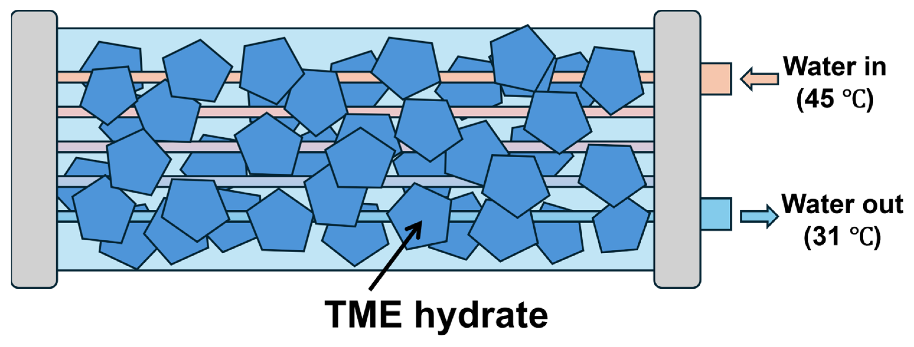
We have employed TME hydrate as a thermal storage compound for the heat exchanger. This section describes a cooling system based on TME hydrate, focusing on heat exchange configurations for cooling LIB packs and the outer (ambient) air to form TME hydrate. The schematic diagram of the LIB cooling system and shell-and-tube heat exchanger with TME hydrate is described in Figure 1 and Figure 2. This system includes the thermal storage tank with TME hydrate. To design the heat exchanger, we employed a shell-and-tube heat exchanger. The shell-and-tube heat exchanger is one of the most common types of heat exchanger that have been used. The basic formula Equations (1)–(5) for calculating heat transfer has been established, and the structure is simple. This heat exchanger is used in various low to high-pressure applications and is made of various materials, including iron and stainless steel. These characteristics simplify the structure and provide redundancy in practical applications. To cool the LIB, the water exchanges the heat with TME hydrate, and the cooled water is supplied to the LIB at high-rate charging. The TME hydrate tank is equipped with a heat exchanger that utilizes outer air to form hydrates and store heat, as the dissociation temperature of TME hydrate is around 30 °C. According to Koyama et al., thermal decomposition measurements of TME hydrate from this study indicate a maximum value of 219.5 kJ/kg at a wTME of 0.65 [26]. Assuming the thermal medium temperature ranges from 20 °C to 40 °C and considering the specific heat of the water to be 4.12 kJ/kg·K, a cooling energy of 82.4 kJ/kg can be derived from the multiplication of specific heat and the temperature difference. For TME hydrate, if we assume a specific heat of 2.75 kJ/kg·K at 10 °C remains constant across temperatures, a cooling energy of 55.0 kJ/kg can be achieved from the temperature difference [34]. When this value is added to the thermal decomposition heat of TME hydrate at 219.5 kJ/kg, the total available cooling energy amounts to 274.5 kJ/kg, more than three times that of water thermal storage capacity. In this study, the physical properties of TME hydrate are set mass fraction of TME solution: wTME = 0.60, H = 190.1   k J / k g . Therefore, it can utilize TME hydrate as a thermal storage medium instead of water, which can reduce the size of the thermal storage tank, resulting in a lighter cooling system.

3.1. TME Hydrate Reservoir (PCM-Based Heat Exchanger)

A typical lithium-ion battery (LIB) pack for electric vehicles should be kept cool, below about 45 °C, to slow capacity degradation and extend its service life [35]. The dissociation heat of the TME hydrate, measured at approximately 30 °C, enables the coolant to maintain a temperature of 31 °C. During the fast 6C charge, the TME hydrate utilizes the enthalpy of decomposing itself to absorb heat, thereby supplying cooled water and stabilizing the temperature of the lithium-ion battery (LIB). This system considers the cooling system of the LIB while estimating the heat generation for electric vehicle (EV) applications. To simplify the calculations, we assumed a constant heat flux from the LIB over a fixed duration and based our design on the total heat load. Chronological changes are important to optimize the design for future practical applications. The LIB heat generation is assumed to be 12 kW; consequently, with a 6C charge for 10 min, the required heat quantity of ideal heat exchange amounts is 7200 kJ. Let the inflow temperature of the refrigerant into the LIB be Tin, and the outflow temperature is Tout; the temperature of the PCM is the equilibrium temperature Teq. A summary of these values of the physical properties of TME hydrate and heat exchanger is shown in Table 1. Tin is established at 45 °C, assuming the LIB is cooled properly and operates within the appropriate temperature range. Tout is set at 31 °C and cooled by the dissociation heat of TME hydrate. The Equations (1) and (2) expresses the situations in which U is constant, describing the overall heat transfer in terms of the average temperature difference between two fluids can address.
Q ˙ = U A Δ T l m
w = U A Δ T l m V P C M
Δ T l m = T i n T o u t ln T P C M T o u t T P C M T i n
The area density A V P C M , and logarithmic mean temperature difference Δ T l m employed for considering the heat exchange. Q ˙ is assumed to be 12 kW. Δ T l m is calculated as 5.84 K. The density of TME hydrate is 1.12 g dm−1 [34]. The ideal weight and volume of TME hydrate matches total heat generation with dissociation heat of TME hydrate is mTME = 38 kg, VTME = 34 m3. To provide leeway for stability and vehicle installation, the minimum volume of TME hydrate is provisional to exceed 0.05 m3.
Based on these values, estimate the practical design and size of the TME hydrate tank unit. Fluid (water) inlet and outlet temperatures for a shell and tube heat exchanger with solid TME hydrate as PCM. Yang et al. reported that the overall heat transfer coefficient was about 1500–3000 W m−2 K−1 in the TBAB + CO2 system [36,37]. Christensen et al. measured the heat transfer coefficient by heating the ice slurry with R134a condensing outside the stainless steel pipe (ID 21.6 mm, OD 26.9 mm, Length = 1 m). This paper reported that the heat transfer coefficient was measured in the range of 2000–5000 W/m2·K depending on velocity (0.7–2.5 m/s) and ice concentration (0–30%) [38]. In this study, condensation is used, but by utilizing phase change in the heat exchange process, the heat transfer coefficient tends to be high. To determine the heating surface area of the thermal storage tank, the overall heat transfer coefficient (U) values are set to 500, 1000, and 2500 W m−2 K−1. This value is assumed by previous experimental measured value in the similar system [36,38]. This calculation utilizes tubes with diameters of 1/4 inch and 1/8 inch. When the tube surface area A m2 and the volume of heat exchanger Vsum m3. The output Q ˙ = 12 kW of the heat exchanger is defined using the equation with the logarithmic mean temperature difference Δ T l m = 5.84 K, and the tube length L [m]. First, the tube length and heating face are calculated using Equations (4) and (5).
L = Q ˙ U π D Δ T l m
A = π D L  
The calculated system design parameters for shell-and-tube heat exchangers with different overall heat transfer coefficients are represented in Table 2; when the overall heat transfer coefficient (U) is set to 500 W m−2 K−1, the area density reaches 77.17 m2/m3. A critical metric for the adequateness of shell-and-tube is the area density A/Vsum used. The relationship between area density and the type of heat exchanger is graphically represented in Figure 3. Higher area density typically implies a more compact heat exchanger design. In our set-up, the shell accommodates PCM (solid TME hydrate) around the tubes, and the coolant flows through the tubes. Hence, the effective heat transfer area is the outer surface of the tubes, while the system volume includes the PCM region and the tube volume. Two TME hydrate volumes are considered: (i) VPCM = 0.05 m3, set for the minimal cooling requirement plus some allowance, and (ii) VPCM = 0.1 m3, which provides additional thermal buffering capacity. When the heat transfer coefficient (U) is set to 500 W m−2 K−1, the area density reaches 100 m2/m3; this value is close to the practical limits of conventional shell-and-tube heat exchanger configurations [39]. In contrast, elevated values of U, such as 1000 or 2500 W m−2 K−1, decrease the requirement of tube length, the corresponding decrease in area density, and facilitating the more compact systems. These results indicate a trade-off relationship between the desired heat transfer coefficient, the total volume of the heat exchanger, and the complexity or compactness of the design.
At a heat transfer coefficient (U) of 500 W m−2 K−1, a tube length or a high area density is essential to achieve adequate heat exchange within the system. This configuration approaches the upper limits commonly observed in standard shell-and-tube designs. U-values close to 1000 or 2500 W m−2 K−1 reduce both the required tube length and overall system volume, thus facilitating integration into electric vehicle structures. However, such a high area density of heat exchanger requires fin and tube, compact heat exchanger, and other complex designs. In electric vehicles (EVs), minimizing weight and volume is important when considering in-vehicle integration. On the other hand, increasing the volume of phase change material increases the redundancy of the system.

3.2. Heat Transfer Coefficient on Waterside

First, consider the heat transfer coefficient on the waterside to consider the feasibility of a heat exchanger. The heat exchanger parameters (tube diameter: 1/4 inch (6.35 mm)) are used. When the thermal conductivity is 500 W m−2 K−1, the Re number of water in the pipe is considered. The system is set in the case of constant wall heat flux. The Dittus–Boelter correlation is employed and expressed in Equation (7). To calculate the Re number of water coolants, using the physical properties of water at 45.0 °C is due to the inlet coolant temperature being set at 45.0 °C. Also, the Nu is expressed with h: heat transfer coefficient [W/(m2·K)], L: characteristic length [m], λ: thermal conductivity of the fluid [W/(m·K)].
N u = h L λ
N u = 0.023 R e 0.8 P r 0.3
The power of the dimensionless Pr number is 0.3 because the fluid is cooled by the pipe wall. Using the thermal conductivity and Prandtl number of water is Pr = 3.788 and k = 0.6309 w/m K at 45.0 °C [39]. The Re number is calculated as 505. The Reynolds number is not the turbulent flow regime within the laminar flow regime (Re < 2300). In this case, the heat transfer coefficient is 500, which is the smallest value, and the flow velocity corresponding to the Re number is very small. Therefore, the water flow in the pipe is not the rate-limiting factor of the heat transfer coefficient.

3.3. Detail Design of Pipe Configuration

Iida et al. have reported hydrate formation, and dissociation could be predicted well by classical heat-transfer approaches (e.g., Stefan problems combined with convective heat transfer) [41]. The classical method captures the hydrate formation–melting kinetics and provides reliable verification of our exchanger design. From a one-dimensional Stefan problem, the minimum distance between the pipes was determined using a model that assumes that all energy transferred between the fluid and the TME hydrate is used as dissociation heat. The following assumptions were considered to determine the configuration of the pipes. The TME hydrate is homogeneous and isotropic. The temperature in the tank varies dominantly only in the axial direction with time. To calculate the thickness of the TME hydrate that may melt in 10 min (6C charge). The following Equation (8) assumes a constant heat flux to the TME hydrate. The heat flux is obtained by multiplying the logarithmic mean temperature difference by the heat transfer coefficient.
v m e l t q ˙ ρ H
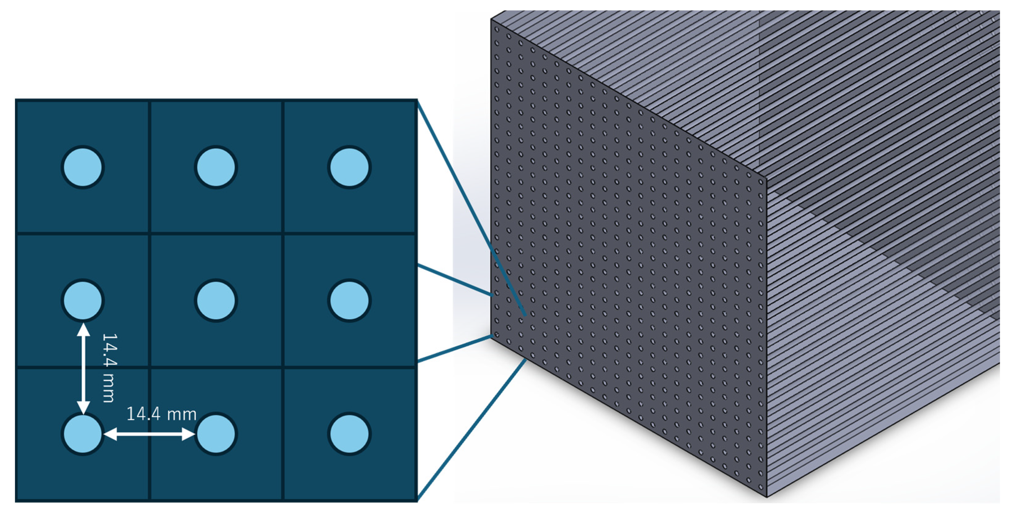
The calculated Dthickness is 7.2 mm. The TME hydrate of this thickness would need to be evenly distributed over the circular tube. The total volume of TME hydrate at that time would be 0.100 m3, and the area density is 45 m2/m3. In this estimation, all the dissociation heat of TME hydrate is used for heat exchange. Assuming it is a cube, the pipe configuration of the shell-and-tube is shown in Figure 4. This pipe-to-pipe length is the basis for designing various shell-and-tube heat exchangers. The amount of TME hydrate in this design is greater than the ideal amount of TME, which means that the system equipment is larger, but not all the TME hydrate is decomposed in a single cooling cycle. In the context of hydrates containing ionic semi-clathrate hydrates, the induction time for nucleation is identified as the rate-limiting step for hydrate formation. Consequently, the memory effect is frequently employed to reduce the induction time [42]. In this estimation, a greater margin is allotted than the amount of TME hydrate necessary for a single cycle. As a result, the system remains in a solid state after the decomposition process, with TME hydrate remaining in the system. Yamamoto et al. have verified 200-cycle stability in a related hydrate system [43]. Multiple-cycle tests specific to TME hydrates have not been performed. With the tetrabutylammonium hydrate and tetrabutylphosphonium hydrate, the same basic properties would suggest that TME hydrate would likewise exhibit durable thermal performance over many cycles. With respect to volumetric expansion, the total density of TME hydrates is about 1.12 g cm−3 at 283 K whereas the TEM solution density is 1.09 g cm−3 at 323 K [34]. Therefore, the volume of hydrates fluctuates between the phases of melting and solidification, demonstrating a significant reduction compared to the typical volume associated with ice-based phase change materials (PCMs). Consequently, TME hydrates present a stable, repeatedly rechargeable phase-change medium, which alleviates concerns regarding large expansion pressures typically encountered with other compounds. Consequently, when TME hydrate reformation, the necessity for nucleation is eliminated, and the interval becomes the formation time when the process is repeated. The specific shell-and-tube heat exchanger obtained in this section is shown in Table 3.

3.4. The Heat Exchange with the Outer Air

Decomposition of TME hydrates effectively stabilizes coolant temperatures around 30 °C, but outdoor air often exceeds this temperature during the summer months. The conceptual design of heat exchanger with outer-air (Cooling tower) is shown in Figure 5. Therefore, the system can include an outdoor air heat exchange mechanism to promote TME hydrate formation and improve overall cooling efficiency. Key elements include an air cooling stage and spray cooling/evaporative cooling. If the ambient air is hot but the wet bulb temperature is relatively low, the mist system can reduce the air temperature through evaporation. If a heat exchanger is installed with the ambient air, a heat pump-based cooling system becomes unnecessary. Ambient air is passed through a dedicated heat exchanger or duct so that the TME solution loses thermal energy. Cooling towers cool circulating water primarily through the action of evaporative cooling. As water is dissipated internally, some of it evaporates and releases heat as latent heat to the surrounding air, lowering the temperature of the remaining water. The theoretical limit is the wet bulb temperature of the outside air. Once the wet bulb temperature is reached, the air is saturated, further evaporation cannot proceed, and the temperature of the water cannot be lowered any further. The difference between theoretical and practical values is that, ideally, with an infinitely large cooling tower and sufficient airflow, water would cool to the wet-bulb temperature of the air (approach = 0). In practice, however, the approach (=difference between cooling water temperature and wet bulb temperature) needs to be about 2 to 5 °C. To keep the approach below 1 °C, large cooling towers and powerful fans are required, and cost and energy consumption skyrocket. In actual HVAC (air conditioning) applications, an approach of 3 to 5 °C is a good design guideline. Most building HVAC systems are designed so that the cooling tower inlet temperature (condenser outlet, etc.) is around 37 °C, and the cooling tower outlet (water tank side) is around 32 °C. In other words, the operation that ensures a temperature difference of about 5 °C is common. In some cases, lower cooling water temperatures can be obtained at night or in early fall since the wet bulb temperature also drops as the humidity drops. This process promotes the formation of TME hydrates even when the outside temperature is near or above 30 °C. Passing the cooled outdoor air into the TME solution, the solution temperature drops below the equilibrium temperature of the TME hydrate, and the PCM is regenerated. Fins may be added to the tubes/plates to promote convective heat transfer with the flowing air. By integrating the outdoor air heat exchange stage with the TME hydrate unit, the system achieves the dual benefit of charging the TME solution in hydrate form at night or during off-peak hours when outdoor temperatures and loads are low.

4. Conclusions

This study investigated the thermal management of high-power lithium-ion batteries (LIBs) by implementing a PCM-based heat exchange cooling system using TME hydrate. The main objective of this study was to determine the optimal heat exchanger configuration and the appropriate volume of PCM required to maintain safe operating temperatures under high C-rate conditions while minimizing system size and weight. Illustrative results show that TME hydrates can provide up to three times the cooling capacity of water, as their latent heat of decomposition occurs at approximately 30 °C. By incorporating various total heat transfer coefficients (U = 500, 1000, and 2500 W m−2 K−1) into the shell-and-tube design calculations, it has been shown that larger U values significantly reduce the required tube length and overall system size. In addition, when supplemented with ambient air or evaporative cooling stages, TME hydrate systems can maintain efficient operation as ambient temperatures rise, effectively reducing the risk of battery overheating during rapid charge cycles. The proposed shell-and-tube is approximately 0.1 m3 in size, which may be too large to mount in a vehicle, but given the reduction in heat dissipation during charging, it should be integrated into the charging station.

Author Contributions

Conceptualization, R.K., L.K., Y.A. and R.O.; methodology, R.K. and L.K.; validation, formal analysis, Y.A. and L.K.; investigation, R.K and L.K.; data curation, R.K., Y.A. and L.K.; writing—original draft preparation, R.K., Y.A. and L.K.; writing—review and editing, L.K. and R.O.; visualization, L.K.; supervision, R.O.; project administration, R.O. All authors have read and agreed to the published version of the manuscript.

Funding

This research was funded by the Keirin-racing-based research-promotion fund from the JKA Foundation, grant number 2024M-550.

Data Availability Statement

The original contributions presented in the study are included in the article, further inquiries can be directed to the corresponding author.

Acknowledgments

The authors are grateful for the System Brain Inc. (Sapporo, Japan) for arranging reagents.

Conflicts of Interest

The authors declare no conflicts of interest.

References

  1. Karimi, G.; Li, X. Thermal management of lithium-ion batteries for electric vehicles. Int. J. Energy Res. 2013, 37, 13–24. [Google Scholar] [CrossRef]
  2. Khateeb, S.A.; Farid, M.M.; Selman, J.R.; Al-Hallaj, S. Design and simulation of a lithium-ion battery with a phase change material thermal management system for an electric scooter. J. Power Sources 2004, 128, 292–307. [Google Scholar] [CrossRef]
  3. Rao, Z.; Wang, S. A review of power battery thermal energy management. Renew. Sustain. Energy Rev. 2011, 15, 4554–4571. [Google Scholar] [CrossRef]
  4. Wang, X.; Xie, Y.; Day, R.; Wu, H.; Hu, Z.; Zhu, J.; Wen, D. Performance analysis of a novel thermal management system with composite phase change material for a lithium-ion battery pack. Energy 2018, 156, 154–168. [Google Scholar] [CrossRef]
  5. Chen, G.; Shi, Y.; Yu, Y. A thermal management design using phase change material in embedded finned shells for lithium-ion batteries. Int. J. Heat Mass. Transf. 2024, 229, 125680. [Google Scholar] [CrossRef]
  6. Feng, X.; Ouyang, M.; Liu, X.; Lu, L.; Xia, Y.; He, X. Thermal runaway mechanism of lithium ion battery for electric vehicles: A review. Energy Storage Mater. 2018, 10, 246–267. [Google Scholar] [CrossRef]
  7. Xin, Q.; Yang, T.; Zhang, H.; Yang, J.; Zeng, J.; Xiao, J. Experimental and numerical study of lithium-ion battery thermal management system using composite phase change material and liquid cooling. J. Energy Storage 2023, 71, 108003. [Google Scholar] [CrossRef]
  8. Chavan, S.; Venkateswarlu, B.; Salman, M.; Liu, J.; Pawar, P.; Joo, S.W.; Choi, G.S.; Kim, S.C. Thermal management strategies for lithium-ion batteries in electric vehicles: Fundamentals, recent advances, thermal models, and cooling techniques. Int. J. Heat Mass. Transf. 2024, 232, 125918. [Google Scholar] [CrossRef]
  9. Fan, L.; Khodadadi, J.M.; Pesaran, A.A. A parametric study on thermal management of an air-cooled lithium-ion battery module for plug-in hybrid electric vehicles. J. Power Sources 2013, 238, 301–312. [Google Scholar] [CrossRef]
  10. Wang, D.; Xie, J.; Wang, D.; Xie, J. Investigation of the Liquid Cooling and Heating of a Lithium-Ion Battery Package for an Electric Vehicle. World Electr. Veh. J. 2023, 14, 169. [Google Scholar] [CrossRef]
  11. Park, H. A design of air flow configuration for cooling lithium ion battery in hybrid electric vehicles. J. Power Sources 2013, 239, 30–36. [Google Scholar] [CrossRef]
  12. Wang, S.; Ma, Z. Supervisory and optimal control of building HVAC systems: A review. HVAC R Res. 2008, 14, 3–32. [Google Scholar] [CrossRef]
  13. Sanaye, S.; Shirazi, A. Thermo-economic optimization of an ice thermal energy storage system for air-conditioning applications. Energy Build. 2013, 60, 100–109. [Google Scholar] [CrossRef]
  14. MacPhee, D.; Dincer, I. Performance assessment of some ice TES systems. Int. J. Therm. Sci. 2009, 48, 2288–2299. [Google Scholar] [CrossRef]
  15. Oró, E.; de Gracia, A.; Castell, A.; Farid, M.M.; Cabeza, L.F. Review on phase change materials (PCMs) for cold thermal energy storage applications. Appl. Energy 2012, 99, 513–533. [Google Scholar] [CrossRef]
  16. da Cunha, J.P.; Eames, P. Thermal energy storage for low and medium temperature applications using phase change materials—A review. Appl. Energy 2016, 177, 227–238. [Google Scholar] [CrossRef]
  17. Tsai, W.T. An overview of environmental hazards and exposure risk of hydrofluorocarbons (HFCs). Chemosphere 2005, 61, 1539–1547. [Google Scholar] [CrossRef]
  18. Matsuura, R.; Maruyama, M.; Ohmura, R. Review of Ionic Semiclathrate Hydrates as Thermal Energy Storage Materials: Properties and Applications. ACS Appl. Eng. Mater. 2024, 2, 503–520. [Google Scholar] [CrossRef]
  19. Antunes, A.H.P.; Filho, E.P.B. Experimental investigation on the performance and global environmental impact of a refrigeration system retrofitted with alternative refrigerants. Int. J. Refrig. 2016, 70, 119–127. [Google Scholar] [CrossRef]
  20. Sanker, S.B.; Baby, R. Phase change material based thermal management of lithium ion batteries: A review on thermal performance of various thermal conductivity enhancers. J. Energy Storage 2022, 50, 104606. [Google Scholar] [CrossRef]
  21. Nakajima, M.; Ohinura, R.; Mori, Y.H. Clathrate hydrate formation from cyclopentane-in-water emulsions. Ind. Eng. Chem. Res. 2008, 47, 8933–8939. [Google Scholar] [CrossRef]
  22. Delroisse, H.; Plantier, F.; Marlin, L.; Dicharry, C.; Frouté, L.; André, R.; Torré, J.P. Determination of thermophysical properties of cyclopentane hydrate using a stirred calorimetric cell. J. Chem. Thermodyn. 2018, 125, 136–141. [Google Scholar] [CrossRef]
  23. Masahiro, N.; Atsushi, H. High-Efficient Thermal Energy Storage Technique with a Clathrate Hydrate. IHI Eng. Rev. 2009, 4, 210–218. [Google Scholar]
  24. Muromachi, S.; Udachin, K.A.; Alavi, S.; Ohmura, R.; Ripmeester, J.A. Selective occupancy of methane by cage symmetry in TBAB ionic clathrate hydrate. Chem. Commun. 2016, 52, 5621–5624. [Google Scholar] [CrossRef] [PubMed]
  25. Kiyokawa, H.; Kondo, Y.; Koyama, R.; Kurokawa, N.; Atsushi, H.; Alavi, S.; Ota, I.; Ohmura, R. Pinacol hydrate as a novel thermal energy storage medium for electric vehicles. J. Energy Storage 2022, 51, 104404. [Google Scholar] [CrossRef]
  26. Koyama, R.; Arai, Y.; Yamauchi, Y.; Takeya, S.; Endo, F.; Hotta, A.; Ohmura, R. Thermophysical properties of trimethylolethane (TME) hydrate as phase change material for cooling lithium-ion battery in electric vehicle. J. Power Sources 2019, 427, 70–76. [Google Scholar] [CrossRef]
  27. Kakiuchi, H.; Yabe, M.; Yamazaki, M. A Study of Trimethylolethane Hydrate as a Phase Change Material. J. Chem. Eng. Jpn. 2003, 36, 788–793. [Google Scholar] [CrossRef]
  28. Kiyokawa, H.; Tokutomi, H.; Ishida, S.; Nishi, H.; Ohmura, R. Thermal Energy Storage Performance of Tetrabutylammonium Acrylate Hydrate as Phase Change Materials. Appl. Sci. 2021, 11, 4848. [Google Scholar] [CrossRef]
  29. Liu, H.; Wei, Z.; He, W.; Zhao, J. Thermal issues about Li-ion batteries and recent progress in battery thermal management systems: A review. Energy Convers. Manag. 2017, 150, 304–330. [Google Scholar] [CrossRef]
  30. Shabani, B.; Biju, M. Theoretical modelling methods for thermal management of batteries. Energies 2015, 8, 10153–10177. [Google Scholar] [CrossRef]
  31. An, Z.; Jia, L.; Ding, Y.; Dang, C.; Li, X. A review on lithium-ion power battery thermal management technologies and thermal safety. J. Therm. Sci. 2017, 26, 391–412. [Google Scholar] [CrossRef]
  32. Dai, N.; Long, J. Research on fast-charging battery thermal management system based on refrigerant direct cooling. Sci. Rep. 2023, 13, 11707. [Google Scholar] [CrossRef] [PubMed]
  33. Abada, S.; Marlair, G.; Lecocq, A.; Petit, M.; Sauvant-Moynot, V.; Huet, F. Safety focused modeling of lithium-ion batteries: A review. J. Power Sources 2016, 306, 178–192. [Google Scholar] [CrossRef]
  34. Yamazaki, M.; Sasaki, C.; Kakiuchi, H.; Osano, Y.T.; Suga, H. Thermal and structural characterization of trimethylolethane trihydrate. Thermochim. Acta 2002, 387, 39–45. [Google Scholar] [CrossRef]
  35. Ma, S.; Jiang, M.; Tao, P.; Song, C.; Wu, J.; Wang, J.; Deng, T.; Shang, W. Temperature effect and thermal impact in lithium-ion batteries: A review. Prog. Nat. Sci. Mater. Int. 2018, 28, 653–666. [Google Scholar] [CrossRef]
  36. Yang, K.; Chen, Z.; Zhang, P. Production and flow behaviors of CO2+TBAB hydrate slurry for cold storage and transport application. Energy 2025, 316, 134485. [Google Scholar] [CrossRef]
  37. Yang, K.; Guo, W.; Zhang, P. Cold energy transport and release characteristics of CO2+TBAB hydrate slurry flow with hydrate dissociation. Energy 2024, 294, 130620. [Google Scholar] [CrossRef]
  38. Christensen, K.G.; Kauffeld, M. Heat Transfer Measurements with Ice Slurry. In Proceedings of the IIR/IIF International Conference, Heat Transfer Issues in Natural Refrigerants, College Park, MD, USA, 6–7 November 1997. [Google Scholar]
  39. The Japan Society of Mechanical Engineers. Data Book Thermophysical Properties of Fluids; JSME: Fukuoka, Japan, 1983. [Google Scholar]
  40. Japan Society Mechanical Engineering. JSME Data Book: Heat Transfer; Japan Society Mechanical Engineering: Fukuoka, Japan, 2009; Volume 6, 332p. [Google Scholar]
  41. Iida, T.; Mori, H.; Mochizuki, T.; Mori, Y.H. Formation and dissociation of clathrate hydrate in stoichiometric tetrahydrofuran–water mixture subjected to one-dimensional cooling or heating. Chem. Eng. Sci. 2001, 56, 4747. [Google Scholar] [CrossRef]
  42. Kim, H.; Zheng, J.; Babu, P.; Kumar, S.; Tee, J.; Linga, P. Key factors influencing the kinetics of tetra-n-butylammonium bromide hydrate formation as a cold storage and transport material. Chem. Eng. J. 2022, 446, 136843. [Google Scholar] [CrossRef]
  43. Yamamoto, K.; Iwai, T.; Hiraga, K.; Miyamoto, T.; Hotta, A.; Ohmura, R. Synthesis and thermophysical properties of Tetrabutylammonium picolinate hydrate as an energy storage phase change material for cold chain. J. Energy Storage 2022, 55, 105812. [Google Scholar] [CrossRef]
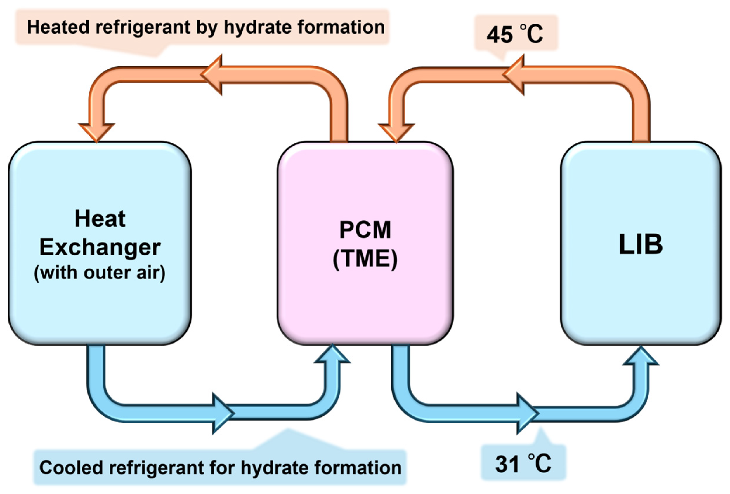
Figure 1. The schematic diagram of the LIB cooling system.
Energies 18 01457 g001
Figure 2. The schematic diagram of shell-and-tube heat exchanger with TME hydrate.
Energies 18 01457 g002
Figure 3. The type of heat exchanger and Area density [40].
Energies 18 01457 g003
Figure 4. The pipe configuration of the shell-and-tube heat exchanger: the inner tube is 0.635 cm.
Energies 18 01457 g004
Figure 5. The schematic model of heat exchanger with outer-air (Cooling tower).
Energies 18 01457 g005
Table 1. The physical properties of TME hydrate and the parameter of shell-and-tube heat exchanger with TME hydrate and system set-ups.
Parameters.Value
Dissociation   heat   of   TME   hydrate   ( w TME = 0.60 )   H d / k J k g 1 190.1
Dissociation temperature of TME hydrate (wTME = 0.60) Teq/°C29.6
Logarithmic   mean   temperature   difference   Δ T l m 5.84
The inlet temperature of coolant Tin/°C45.0
Outlet temperature of coolant Tout/°C31.0
Heat   transfer   rate   Q ˙ /kW12.0
Table 2. System design parameters for shell-and-tube heat exchangers with different overall heat transfer coefficients.
Overall Heat Transfer: U/W m−2 K−150010002500
Tube length (1/4 inch): L/m206.0103.041.2
Tube length (1/8 inch): L/m412.1206.082.4
System volume; PCM = 0.05: V (1/4 inch)/m30.056520.053260.05065
System volume; PCM = 0.1 m3: V (1/4 inch)/m30.10650.10320.1013
Area density; A/V (PCM = 0.05 m3):/m2/m377.1738.5916.02
Area density; A/V (PCM = 0.1 m3):/m2/m339.8019.908.11
Table 3. The system of the TME hydrate reservoir (PCM-based shell-and-tube heat exchanger).
ParametersValue
Total system volume m30.100
The volume of TME hydrate m30.0926
Tube length (1/4 inch): L/m232.7
Logarithmic   mean   temperature   difference   Δ T l m 5.84
The inlet temperature of coolant Tin/°C45.0
Outlet temperature of coolant Tout/°C31.0
Heat   transfer   rate   Q ˙ /kW12.0
Assumed heat transfer coefficients500
Heating face m24.65
Area density m2/m346.5
Thermal storage capacity kJ19,715
Disclaimer/Publisher’s Note: The statements, opinions and data contained in all publications are solely those of the individual author(s) and contributor(s) and not of MDPI and/or the editor(s). MDPI and/or the editor(s) disclaim responsibility for any injury to people or property resulting from any ideas, methods, instructions or products referred to in the content.