Article

Research on Thermo-Mechanical Response of Solid-State Core Matrix in a Heat Pipe Cooled Reactor

1
Department of Nuclear Science and Technology, College of Physics and Optoelectronic Engineering, Shenzhen University, Shenzhen 518060, China
2
Shaanxi Key Laboratory of Advanced Nuclear Energy and Technology, School of Nuclear Science and Technology, Xi’an Jiaotong University, Xi’an 710049, China
*
Author to whom correspondence should be addressed.
Energies 2025, 18(6), 1423; https://doi.org/10.3390/en18061423
Submission received: 17 February 2025 / Revised: 9 March 2025 / Accepted: 10 March 2025 / Published: 13 March 2025
(This article belongs to the Special Issue Optimal Design and Analysis of Advanced Nuclear Reactors)

Abstract

:
Due to its advantages of simple structure and high inherent safety, the heat pipe cooled reactor (HPR) could be widely applied in deep-sea navigation, deep-space exploration and land-based power supply as a promising advanced special nuclear power equipment option. In HPRs, the space between the components (fuel rods and heat pipes) is filled with solid matrix material, forming a continuous solid reactor core. Thermo-mechanical response of the solid core is a special issue for HPRs and has great impacts on reactor safety. Considering the irradiation and burnup effects, the thermal and mechanical modeling of an HPR was conducted with ABAQUS-2021 in this study. The thermo-mechanical response under long-term normal operation, accident transients and single heat pipe failed conditions was simulated and analyzed. The whole core presents relatively good isothermality due to the high thermal conductivity of the solid matrix. As for the mechanical performance, the maximum stress was about 300 MPa, and the maximum displacement of the matrix could be as high as 3.7 mm. It could lead to significant variation of the reactor physical parameters, which warrants further attention in reactor design and safety analysis. Reactivity insertion accidents or single heat pipe failure has obvious influence on the thermo-mechanical performance of the local matrix, but they did not cause any failure risks, because the HPR design eliminates the dramatic power flash-up and the solid-state core avoids the heat transfer crisis caused by the coolant phase transition. A quantitative evaluation of thermo-mechanical performance was completed by this research, which is of great value for reactor design and safety evaluation of HPRs.

1. Introduction

The energy demand in special physical spaces, such as deep sea, deep space and isolated islands, is growing rapidly. Since nuclear energy has incomparable advantages over other energy sources in terms of energy density and reliability, it is the primary energy choice for high-intensity exploration and development in special spaces [1,2]. The heat pipe cooled reactor (HPR) adopts a solid core design and removes the heat from the core in a passive way through heat pipes. Due to its advantages of simple reactor structure, high inherent safety characteristics and easy modular design and expansion, HPR has the potential to change the future nuclear power pattern and has broad application prospects in deep-sea submersible navigation, deep space exploration, land-based nuclear power and other scenarios.
Since the concept of HPR was proposed in the 1960s, it has been widely concerned in the field of nuclear engineering. Before this century, the United States and the former Soviet Union carried out research on key technologies around the application of HPRs in aerospace, such as heat-resisting materials, high-density fuels and high-temperature heat pipes [3]. In 2002, Los Alamos National Laboratory (LANL) proposed the design scheme of “HOMER” [4] HPR, which became the foundation for subsequent HPR designs. Subsequently, “Kilopower” [5], “LEGO” [6], “MSR” [7] and “MegaPower” [8] HPRs have been put forward for different application scenarios, with the power increased from kilowatt level to megawatt level. LANL has completed the overall nuclear power generation tests for an HPR coupled with a Stirling motor under stable, transient and accident conditions, proving the safety and reliability of HPRs [9]. As for the academic aspect, numerous studies have been carried out, involving neutronics [10,11], heat transfer analysis of heat pipes [12,13], thermoelectric conversion [14,15], etc.
The above research greatly promoted the development and application of HPRs. There exists a special issue for HPRs that is the thermo-mechanical response of the solid matrix. Although the matrix in an HPR is distributed with many holes containing fuel rods and heat pipes, the matrix is, geometrically, a continuous whole. Therefore, all the mechanical loads exerted at different areas of the matrix are actually acting on one continuous body, which can have a cumulative effect. For example, the thermal expansion of each fuel rod is independent in a conventional Light Water Reactor (LWR), while the thermal expansion at each position of the HPR matrix is interrelated, which results in a much larger displacement in the periphery of the core. Hence, the solid-state core of an HPR has obvious dynamic geometric characteristics. With the long-term creep or large thermal expansion under long-term operation or fast transient conditions, the deformation of an HPR core could be rather considerable and might significantly change the physical characteristics of the reactor core. In addition, compared with large LWRs, HPRs have a significant characteristic of fast transient response and even allow short-time over-fixed power operation within the thermal operation limit of the materials. Under the action of non-uniform and rapidly changing temperature, the honeycomb core matrix will undergo significant and complex deformation. What’s more, fuel rods in the core are connected with the solid matrix, which intensifies the transfer and interaction of thermo-mechanical loads at different spatial positions, making the thermo-mechanical response of the matrix more complicated. High-temperature heat pipes are rather complex systems, and their working process involves a variety of heat-transfer forms and a working medium-phase transition process [16,17]. Strong transient thermal impact may lead to an increase in operating temperature, the deterioration of heat transfer in the condensing section and the deterioration of capillary wick performance, finally resulting in the failure of the heat pipes [18,19]. The failure of a heat pipe also significantly changes the thermo-mechanical behavior of the local matrix.
At present, a lot of physical analysis, thermal analysis and nuclear–thermal coupling analyses have been carried out for HPR design and optimization [10,11,12,13,20,21,22]. In the studies of nuclear physical analysis [10,11], it was demonstrated that the HPR reactor core could be operated for more than 10 years without the need for refueling. In addition, the optimal design for moderator materials and shutdown mechanisms was performed to ensure the safety and reliability of the HPR. In the studies of thermal–hydraulic analysis [12,13,20], the heat-transfer characteristics and safety performance of HPRs were quantitatively studied, including the prediction of the fuel temperature and heat transfer coefficient of heat pipes under normal, transient and accident conditions. The advantages of HPRs in respect to superior inherent safety and low maintenance demand were fully confirmed by these studies. In the studies of nuclear–thermal coupling analysis [21,22], the thermal–hydraulic calculation model was coupled with the point reactor kinetics model to improve the simulation accuracy, and the safety performance under normal and accident conditions was evaluated with the consideration of nuclear–thermal coupling effects. However, the deformation of the solid core and its influence was rarely considered in those studies, resulting in great uncertainty in performance analysis and safety evaluation for HPRs. Considering its influence on the safety of HPRs, it is necessary to conduct the study on the thermo-mechanical response of the solid core under different operation conditions, such as long-term normal operation, single heat pipe failure conditions and fast transient conditions. In addition, due to the solid-state core design, the study of the thermo-mechanical response of an HPR should be carried out at the full-core scale.
This study aimed to make up for the shortcomings in the current research mentioned above and obtain the dynamic geometric deformation characteristics of the solid core, thermal and mechanical modeling of an HPR proposed by Xi’an Jiaotong University [23]. It was conducted with full consideration of irradiation. The thermo-mechanical coupling analysis capability for the HPR was developed with ABAQUS-2021 software and preliminarily validated by an out-pile experiment. After that, full-core scale numerical simulations were carried out to investigate the thermo-mechanical response of the HPR under long-term normal operation, accident transients and single heat pipe failed conditions. This study is expected to reveal the creep and deformation characteristics of a honeycomb matrix under non-uniform thermal and mechanical loads and to quantitatively grasp the maximum scale matrix deformation of the solid core under accident conditions.

2. Methodology and Validation

2.1. HPR Design

The research object of this paper is an HPR designed by Xi’an Jiaotong University [23]. The design scheme of the core geometry is illustrated in Figure 1, and major design parameters are presented in Table 1. The core of this HPR is mainly composed of 54 fuel rods, 37 heat pipes and the solid matrix filled in between them, with a total thermal power of 500 kW. It should be noted that the design value of heat transfer of a single heat pipe is as high as 30 kW due to its large-diameter (52 mm) design. A total of 54 fuel rods are divided into 3 types with different enrichment. Each heat pipe works independently. Hence, even if a few heat pipes fail, the fission heat can still be efficiently removed by other pipes, greatly improving the reliability of the reactor. The whole core is surrounded by a side, a top and a bottom reflector, which is made of BeO. The radial reflector contains 6 control/safety drums with independent drive motors. The reactivity and power of the HPR can be effectively adjusted by turning the drums. The enrichment of all fuels is pretty high (but still within the limit of 20%), in order to achieve a long-life operation (30 years) without any refueling, to adapt to special application scenarios, such as deep space exploration and power supply on planetary surface. It should be noted that the reactor physics design and analysis is out of the scope of this study, so other details about the reactor design will not be discussed in this paper.

2.2. Material Property Models

2.2.1. Stainless Steel 316 [24]

In this study, the thermal, mechanical and failure models for SS316 were developed. As for the irradiation effects, the creep due to both thermal and irradiation was considered. Data about the influence of irradiation on mechanical strength are scarce. In 2019, Westinghouse tested the tensile properties of additive manufacturing SS316L after neutron irradiation and found that the tensile strength and yield strength increased while the elongation decreased slightly after irradiation [25]. Therefore, from a conservative point of view, the strength data of the 316 material before irradiation were used in this study.
Thermal conductivity of SS316 can be calculated with
k = 7.301 × 10 6 T 2 + 2.716 × 10 2 T + 6.308
where k is thermal conductivity in W/m·K, and T is temperature in K.
Specific heat of SS316 is from
C p = 428.46 + 0.1816 T
where C p is specific heat in J/kg·K.
Young’s modulus and Poisson’s ratio of SS316 can be given as
E = 2.15946 × 10 11 7.07727 × 10 7 T ν = 0.31
where E is Young’s modulus in Pa, and ν is the unitless Poisson’s ratio.
Thermal expansion of SS316 can be calculated by
α S S 316 = 4.34 × 10 3 + 1.45 × 10 5 T + 3.766 × 10 9 T 2
where α S S 316 is the linear thermal expansion coefficient of SS316 in m/m.
The sum of creep rate due to irradiation and thermal can be calculated with
ε ˙ c r = 75 , 776 exp ( 170 , 000 R T ) sinh 0.7 exp ( 12 , 000 R T ) σ + 1.006 × 10 6 ϕ σ
where ε ˙ c r is total creep rate in 1/s; σ is stress in MPa; ϕ is neutron flux in n/cm2·s.
As for the failure criterion of SS316, if the temperature exceeds the melting point (1600 K), thermal failure is considered to have occurred. Since the matrix material works as the medium for heat transfer and provides positioning for fuel rods and heat pipes, rather than the structural body to bear the mechanical load, it is argued that stress failure occurs only when the Mises stress exceeds the Ultimate Tensile Stress (UTS), rather than the Yield Stress (YS). The UTS and YS of SS316 decreases approximately linearly with temperature in the range of 300 to 1000 K, and can be calculated with:
σ U T S = 720.6 0.39 T σ Y S = 399.6 0.34 T
where σ U T S and σ Y S represent the UTS and YS in MPa; T is the temperature in K. In addition, 1% nonlinear (plastic or creep) strain limit, a common failure criterion for engineering materials applications, was also adopted in this study.

2.2.2. UO2 Fuel [26]

Thermal conductivity of the UO2 pellet can be calculated with
k 95 = 1 / ( 0.0452 + t 1 + t 2 + t 3 + t 4 × t 5 ) + t 6 k = 1.0789 k 95 D ( 1 + 0.5 ( 1 D ) ) t 1 = 0.000246 T t 2 = 0.00187 B u t 3 = 1.1599 G d c o n t 4 = ( 1 0.9 exp ( 0.04 B u ) ) 0.038 B u 0.28 t 5 = 1 / ( 1 + 396 exp ( 6380 / T ) ) t 6 = ( 3.5 × 10 9 / T 2 ) exp ( 16360 / T )
where k 95 is thermal conductivity in W/m·K of UO2 fuel with 95% theoretical density; D is the real density fraction of theoretical density; B u is fuel burnup in MWd/kgU; G d c o n is the Gadolinia concentration in wt.%.
Specific heat of the UO2 pellet can be calculated with
C P = 302.27 θ E 2 e θ E / T T 2 ( e θ E / T 1 ) + 1.6926 × 10 2 T + 1.6199 × 1 0 12 e 18531.7 / T T 2
where θ E is Einstein temperature in K, and the value used in this study is 548.68.
Thermal expansion of the UO2 pellet can be calculated with
α u o 2 = 1.0 × 10 5 T 3.0 × 10 3 + 4.0 × 10 2 e ( 6.9 × 10 20 K T )
where α u o 2 is the linear thermal expansion coefficient of UO2 in m/m with the reference temperature of 300 K; K is the Boltzmann constant.
Young’s modulus of UO2 pellet can be given as
E S = 2.269 × 10 2 1.539 × 10 2 T 9.59 × 10 6 T 2 ,   if   T 2610 K 1.334 × 10 3 + 1.181 T 2.388 × 10 4 T 2 ,   if   T > 2610 K E = 1 2.5 P E S ,   if   P 0.3 1 P 1 + 6 P E S ,   if   P > 0.3
where E S is the Young’s modulus in GPa of fuel without porosity; P is the unitless porosity fraction of fuel. Usually, the Poisson’s ratio of the UO2 pellet can be regarded as a constant of 0.316.
During lifetime operation, UO2 fuel will undergo fuel densification and swelling. Densification of UO2 can be calculated by
β d e n = - 3 . 0 + 0 . 93 exp ( B u ) + 2.07 exp ( 35 B u )
where β d e n is the linear fuel shrinkage percentage due to densification in m/m. Fuel swelling can be divided into swelling caused by solid and gaseous fission products, and it can be calculated with
S s = 2.5 × 10 29 B s S g = 8.8 × 10 56 ( 2800 T ) 11.73 e [ 0.0162 ( 2800 T ) ] e [ 8.0 × 10 27 B ] B s
where S s and S g are unitless volume swelling in m3/m3 in the current time step caused by solid and gaseous fission products, respectively; B s means the burnup increase in fissions/m3 during the current time step; B means total burnup in fissions/m3 at the current time step.
A model for combined thermal creep and irradiation creep of the UO2 pellet was used in this study, with the creep rate modeled as a function of time, temperature, effective stress, density, grain size, fission rate and oxygen to metal ratio (O/M). The constitutive relation is given as
ε ˙ c r = 0.3919 + 1.32 × 10 19 F ˙ ( 87.7 + D ) G 2 σ exp ( Q 1 R T ) + 2.0391 × 10 25 ( 90.5 + D ) G 2 σ 4.5 exp ( Q 2 R T ) + 3.7226 × 10 35 F ˙ σ exp ( Q 3 R T )
where G is the grain size in µm; F ˙ is the volumetric fission rate in fissions/m3·s; Q i are the activation energies in J/mol and can be calculated with
Q 1 = 74 , 829 1 exp ( 20 / log ( O / M 2 ) 8 ) + 1 + 301 , 762 Q 2 = 83 , 143 1 exp ( 20 / log ( O / M 2 ) 8 ) + 1 + 469 , 191 Q 3 = 21 , 759

2.3. Thermal and Mechanical Models

2.3.1. Thermal Models

The governing relation of energy balance is given in terms of the heat conduction equation:
ρ C p T t + q e f F ˙ = 0
where ρ is density in kg/m3; t is time in s; e f is the energy released in a single fission event in J; F ˙ is the number of fissions per unit time; and q is the heat flux and can be given as
q = k T
In addition to the thermal governing equation, some other heat transfers should be modeled, such as heat transfer in heat pipes and fuel-cladding gap heat transfer. Considering that heat transfer in a heat pipe is complicated and is not the focus of this research, a simplified model of the heat transfer of heat pipes was adopted in this study. Since the scale of this HPR is very small and the solid matrix has a very high thermal conductivity, the thermal inhomogeneity is very small. In addition, the major aim of this research is to determine the safety characteristics under different thermo-mechanical response conditions. Therefore, the constant heat transfer model with a conservative value can be accepted in this research, which is as follows
h h p = 1.0 × 10 5
where h h p is heat transfer coefficient of the heat pipe in W/m2.
The gas gap heat transfer is divided into gas, radiative and contact heat transfer, and can be modeled as
h g a p = h g a s + h r a d i a t i v e + h c o n t a c t
where h g a p is the gap heat transfer coefficient in W/m2; h g a s , h r a d i a t i v e and h c o n t a c t are heat transfer coefficients in W/m2 due to radiative and contact, respectively. The three terms can be calculated by
h g a s = k g a s d
h r a d i a t i v e = σ F ( T f s 2 + T c i 2 ) ( T f s + T c i )
h c o n t a c t = 0.4166 K m P r e l R m u l t R E , P r e l > 0.003 0.00125 K m R E , 0.003 P r e l > 9 × 10 6 0.4166 K m P r e l 0.5 R E , P r e l 9 × 10 6
More details about gap heat transfer can be found in reference [27].

2.3.2. Mechanical Models

The governing relations of mechanical behavior can be given as the Cauchy’s equation:
σ + ρ f = 0
where σ means the Cauchy stress tensor; f means the body force per unit mass. The displacement field u , which is the primary solution variable, is connected to the stress field via the strain, through a constitutive relation. Since the basic theory of solid mechanics is quite mature and has been incorporated into ABAQUS-2021 as a core module, model details about mechanical models will not be introduced in this paper.
Because both the cladding and matrix in this HPR are made of SS316 and the rod-matrix was assembled with zero tolerance, the claddings and matrix were merged as a whole body in this study. With the long-term fuel swelling due to irradiation, fuel–cladding contact might occur. Therefore, the cladding inner surface and fuel external surface were modeled as the contact couple with a tangential friction coefficient of 0.9 taken from reference [28].

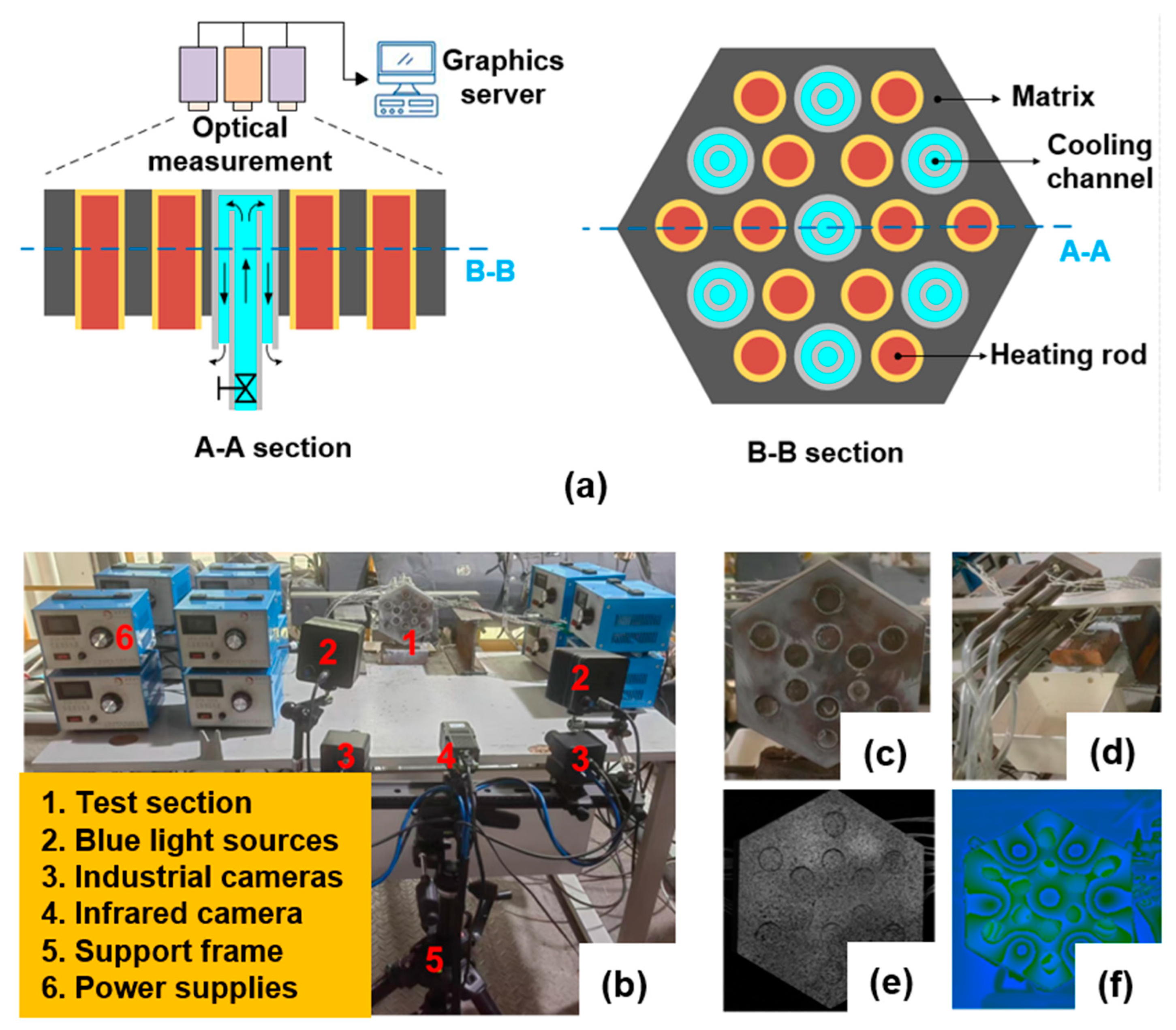
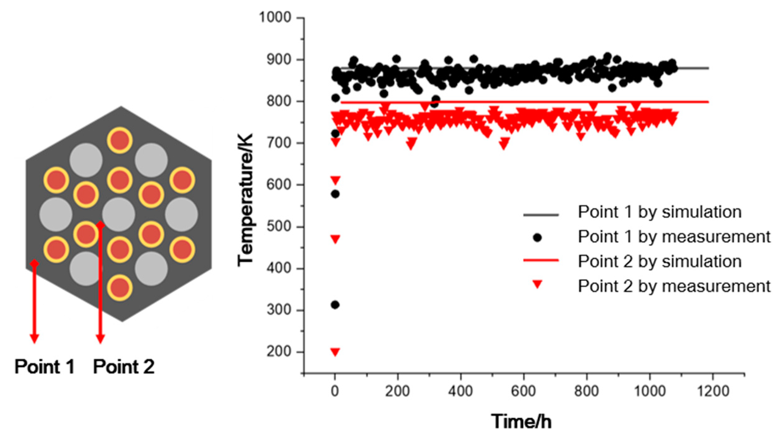
2.4. Simulation Methodology with ABAQUS and Validation

The Finite Element Method (FEM) is widely used in numerical simulations of solid mechanics issues, including nonlinear deformations and contacts under various complex loads. In addition, due to the fast-growing computational capacity of modern high-performance computers, FEM simulation for a large-scale simulation (for example, the full-core thermo-mechanical simulation) has become a reality. As a powerful, well-proven and reliable FEM software, ABAQUS-2021 was adopted as the FEM platform in this study. The above models were implanted into ABAQUS-2021 through user interface parameter settings or user subroutine definitions, building an FEA simulation tool for HPR simulation. Specifically, models of thermal expansion, fuel densification and swelling, creep and gap heat transfer were implanted into the ABAQUS-2021/Standard solver through user the subroutines UEXPAN, CREEP, UMAT and GAPCON, respectively, and coupled to the basic thermo-mechanical solving problem. It should be noted that the time scaling (1 s in the simulation case represents 0.1 day of physical time) was used in the simulation for long-term operation cases to reduce the computational cost. Time scaling is commonly used in quasi-static simulation with ABAQUS-2021 and has been fully proved to be a reasonable and effective method.
Since the HPR proposed by Xi’an Jiaotong University is still at the stage of design optimization, it is very difficult to directly verify the full-core numerical simulation results of this study. Instead, by comparing the measurement results of an out-pile and scaled-down thermo-mechanical experiment, the thermo-mechanical analysis methodology and capability developed based on the ABAQUS-2021 platform in this study was validated. Figure 2 illustrates the design of the out-pile and scaled-down thermo-mechanical experiment, which was composed of a scaled-down test section, two blue light sources, a binocular industrial camera system, an infrared temperature camera, several independent programmable power supplies, a support frame and a graphics server. The honeycomb solid-core test section was composed of a SS316 matrix plate, 12 heating rods (simulators of fuel rods) and 7 reentry water-cooled channels (simulators of heat pipes). With this design, one surface of the test section was free of occlusions, providing conditions for optical measurement. By arranging a Digital Image Correlation (DIC) measuring device coupled with an infrared camera, the non-contact, distributed, temperature-displacement coupling measurement was realized. The out-pile experiment is an important part of our project to investigate the long-term creep behavior of a honeycomb solid core at high temperatures. This paper mainly focuses on the theoretical research, and more details of the experimental part will be introduced in our subsequent articles after the experiment is completed. Although the long-term creep experiment is now still in progress, the current obtained experimental data can still be used to verify the theoretical simulation methodology in this paper. It should be noted that although the experiment is included in the project, the theoretical research in this paper is still very necessary and meaningful for two reasons. First of all, because the experiment will be long-term, economically expensive, and scaled-down, a theoretical simulator is one of the effective tools for HPR design and optimization. In addition, subject to current heating and measurement techniques, the out-pile experiment cannot fully simulate the behavior under extremely harsh conditions, such as the reactivity insertion accident (RIA), while theoretical simulation could be very promising in these cases.
Figure 3, Figure 4 and Figure 5 illustrate the comparison of the matrix temperature during long-term normal steady-state operation, the x displacement distribution under the failure condition of a single heat pipe, and the displacement variation of the matrix with time under the long-term high-temperature creep condition, respectively. The range of the infrared temperature measuring device is 0–2000 K, with the measurement error within ±1.5%. In the benchmark, the maximum and average relative differences between the simulated and measured temperatures were 13.75% and 5.8%, respectively. As for the displacement, the measurement error of the DIC device is within ±0.02 mm. In the benchmark, the maximum and average differences between the simulated and measured displacement were 0.066 mm and 0.035 mm, respectively. Overall, it can be seen that the FEA numerical simulation results based on ABAQUS-2021 were generally in good agreement with the experimental measured values, which proved the correctness and reliability of the numerical models and capability constructed in this study.

3. Simulation Results and Discussion

Based on the models and numerical methodologies established in Section 2, the full-core thermo-mechanical simulation of the HPR was performed under long-life normal operation, single heat pipe failure and RIA conditions. It should be noted that since full-core scale simulation is computationally expensive, a 2D plane (cross section) of a quarter core was selected as the simulation object. Geometry, mesh and boundary conditions of the simulation object are illustrated in Figure 6. Considering the complexity and irregularity of the core geometry, the unstructured mesh was adopted in this study, which was automatically generated with ABAQUS-2021 by specifying the maximum mesh size. A sensitivity analysis for meshing was conducted with maximum mesh sizes of 10 mm, 5 mm, 3 mm, 2 mm and 1 mm, and the mesh with the maximum size of 3 mm was adopted in this study. A uniform heat source was loaded into each fuel rod with a different value. Power factors (power to average power ratio) for all fuel rods are listed in Table 2. These were obtained by the core physical analysis during the reactor design.

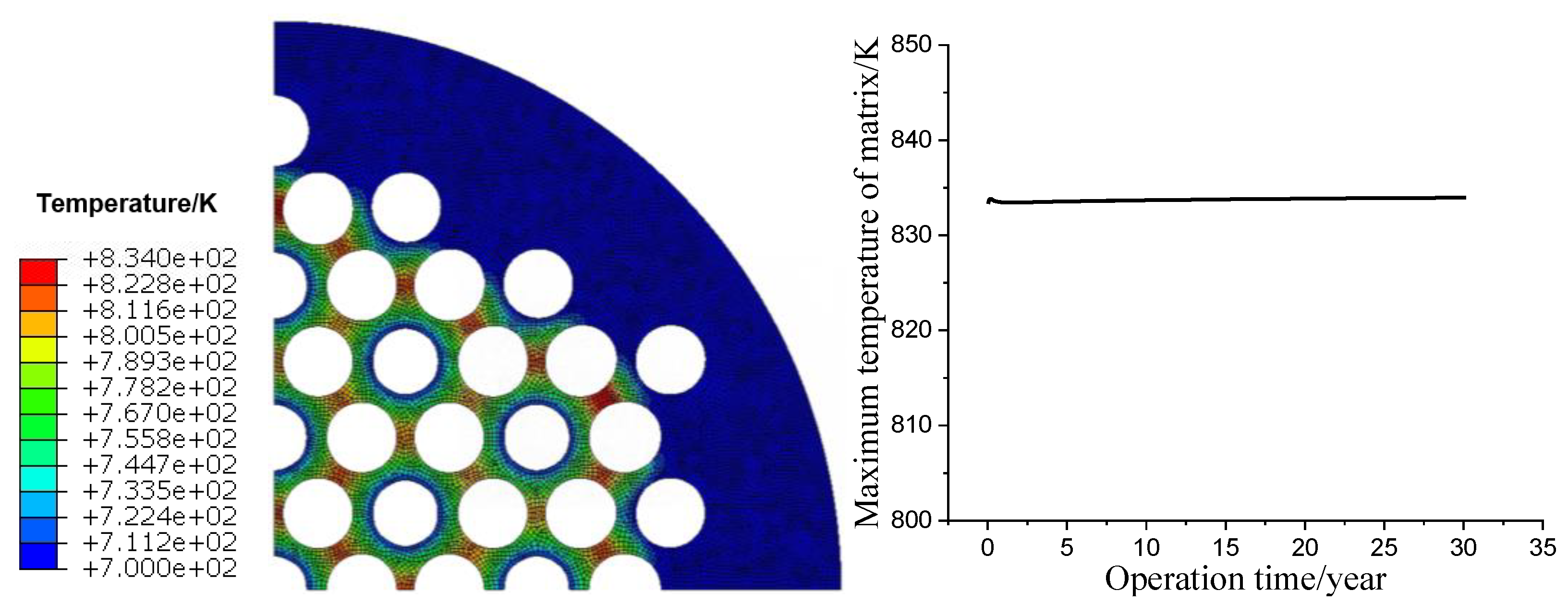
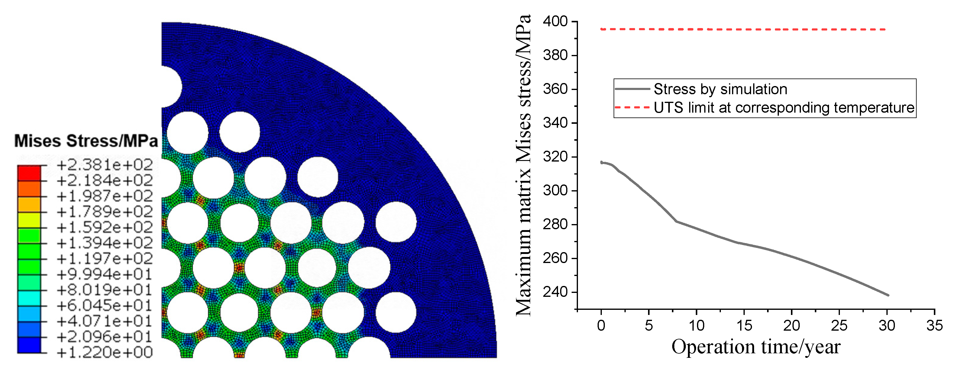
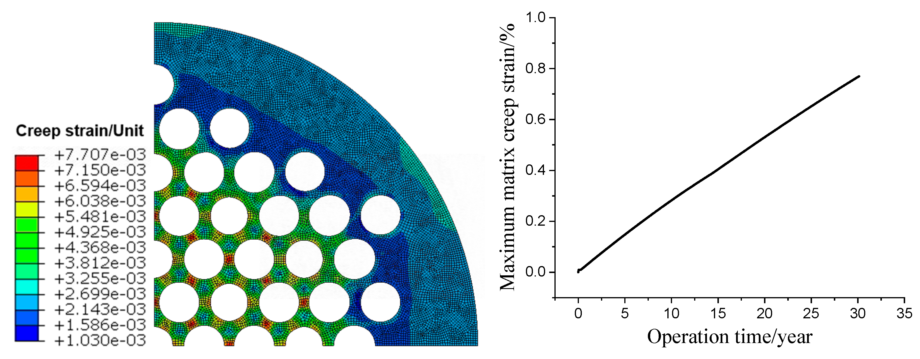
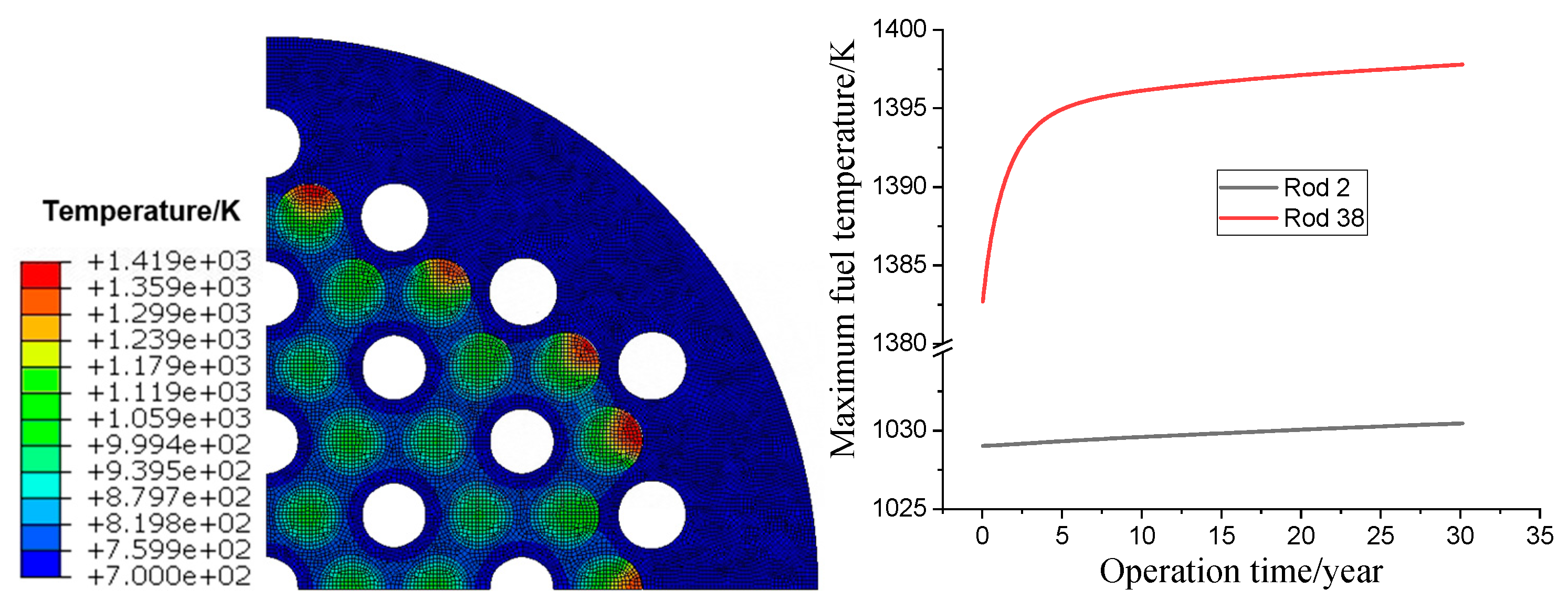
3.1. Long-Life Normal Operation

During the long-life (30 years) normal operation, it was assumed that the total thermal power of the HPR was maintained at 500 KW with a power distribution presented in Table 2. The core matrix temperature profile at the end of operation and the variation of the maximum matrix temperature over the operation time are illustrated in Figure 7 (left) and (right), respectively. According to Figure 7, the maximum temperature of the full-core matrix is located at the region between two adjacent fuel rods, and the value is 834 K, which is significantly lower than the melting point (about 1600 K). It demonstrates the reasonability of the core design and material selection. In addition, the matrix temperature remained almost unchanged during the whole operation.
Figure 8 (left) illustrates the Mises stress profile of the full-core matrix. Similar to the temperature profile, the maximum stress was located at the region between two adjacent fuel rods, which was caused by the squeezing of enlarged fuel rods. As seen in Figure 8 (right), the maximum Mises stress of the matrix decreased gradually from 317 MPa at the initial period to 238 MPa at the end of operation. It was because the creep during long-term operation can release the matrix stress to some extent. Regardless, the maximum stress was substantially lower than the UTS at the corresponding temperature. As illustrated in Figure 9, the creep strain of the matrix increased gradually with the operation time and could be rather considerable. At the end of operation, the maximum creep strain reached 0.8%, which is close to the limit value of 1%. Therefore, the long-term creep of the matrix due to thermal and irradiation is a remarkable and alarming feature for HPRs.
The principal strain profile and displacement magnitude profile of the full-core matrix at the end of long-life operation is presented in Figure 10 (left) and (right), respectively. The maximum principal strain is located at the region between two adjacent fuel rods, with a value as high as 12.4%. Even so, such a magnitude strain will not cause as substantial damages to the matrix as the locator and heat conduction medium for the fuel rods, since SS316 has great ductility at temperatures around 800 K. Different from the strain profile, the overall displacement magnitude of the matrix increased from the center to the periphery of the reactor core. It was because the matrix is continuous and, as a whole, has a cylindrical structure, and the displacement presents the superposition effect from the center to the periphery of the core. The maximum displacement was up to almost 4 mm, which is a rather considerable change to the neutronic parameters of the reactor. It indicates that the HPR exhibits obvious dynamic geometry due to the design of the solid-state core, and it is necessary to carry out the reactor physical analysis with full consideration of the core deformation. Figure 11 illustrates the fuel temperature profile and variation. Except for the outmost fuels, the fuel temperature was lower than 1200 K. However, the temperature at the periphery of the outmost fuels exceeded 1400 K and was significantly higher than others. It was a result of the enlarged fuel–matrix gap caused by the larger displacement magnitude of the matrix at this region (as per the discussion on Figure 10).

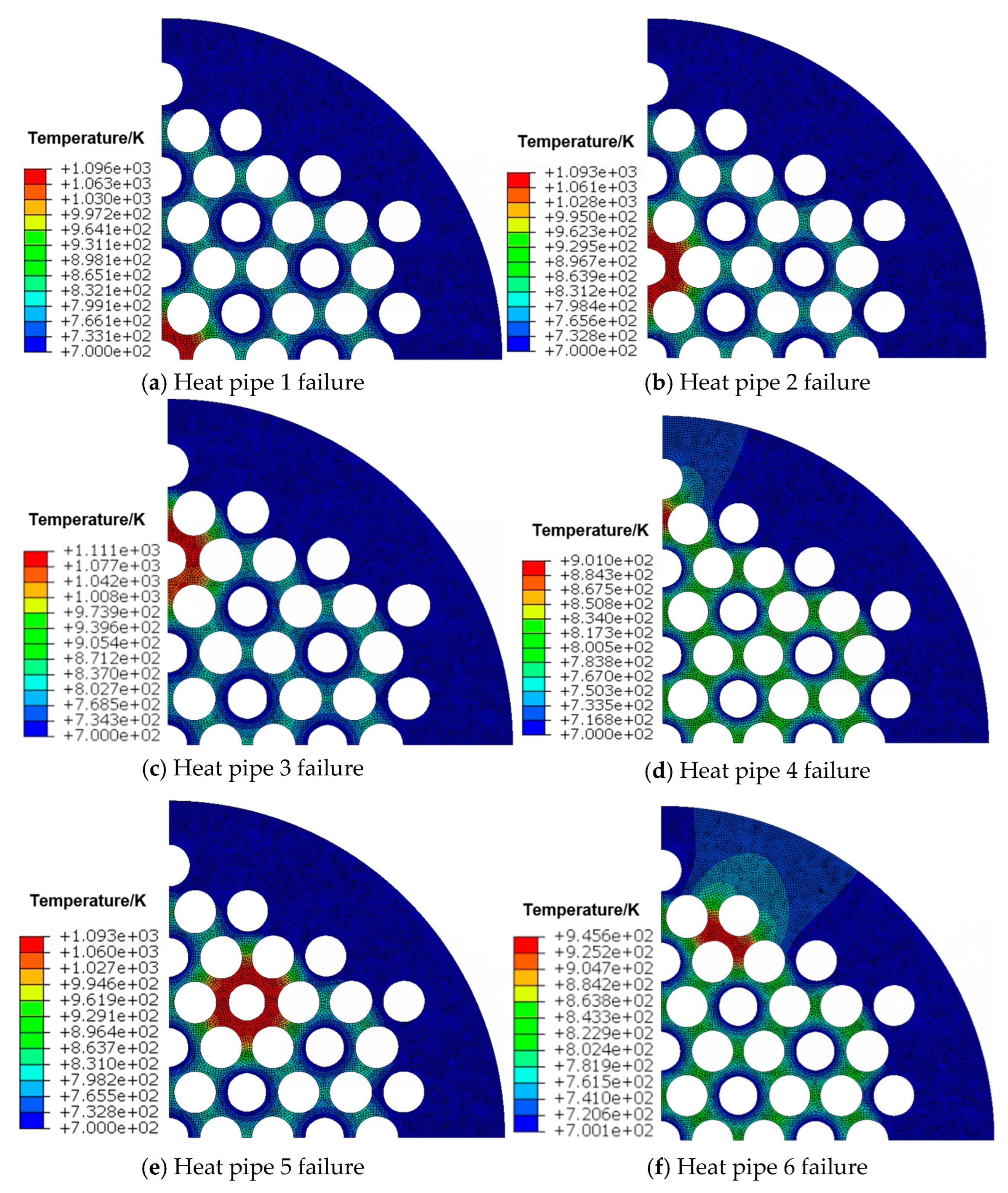
3.2. Operation Under Single Heat Pipe Failed Condition

One advantage of HPRs is their enhanced reliability and robustness, since each heat pipe works independently and does not interfere with the others. In order to verify this advantage, the thermo-mechanical simulation under the condition of single heat pipe failure was conducted. Considering the symmetry of the core geometry, six single heat pipe failure cases were simulated, as seen in Figure 12.
The influence of heat pipe failure on matrix temperature is illustrated in Figure 13. It can be seen that the failure of the heat pipe caused a significant temperature increase of the matrix around the failed heat pipe, while it had little effect on the matrix far away from it. The failure of the heat pipe in the central region (heat pipes 1, 2, 3 and 5) presented greater impact than the failure of the heat pipe in the periphery region (heat pipes 4 and 6). In the most severe case, the failure of a single heat pipe can increase the maximum matrix temperature by about 280 K. Regardless, the maximum temperature was still well below the melting temperature of the matrix material and did not affect its function as the locator and heat conduction medium for the HPRs.
Figure 14 illustrates the influence of single heat pipe failure on the fuel temperature profile. According to Figure 14, the failure of the heat pipe resulted in an obvious temperature increase of the fuel rod around the failed heat pipe, while it had little effect on the matrix far away from it, which was similar to the matrix temperature profile. In the most severe case, the failure of a single heat pipe can increase the maximum fuel temperature by about 220 K. Even so, the peak fuel temperature (about 1640 K) was only 50% of the melting point of ceramic UO2 fuel (about 3300 K). This means that the fuel in the HPRs was still very safe under the condition of single heat pipe failure. In order to intuitively evaluate the influence of single heat pipe failure on the thermo-mechanical performance of the HPR, the maximum values of key parameters of the no heat pipe failure case and the six single heat pipe failure cases are summarized in Table 3. According to the results of Figure 14 and Table 3, it can be concluded that the HPR can well survive the accident of a single fuel failure, although it did have an impact on thermo-mechanical performance. However, the maximum matrix displacement could increase by about 20%. The increase of local matrix deformation due to the heat pipe failure could exert a non-negligible impact on the reactor’s physical characteristics.

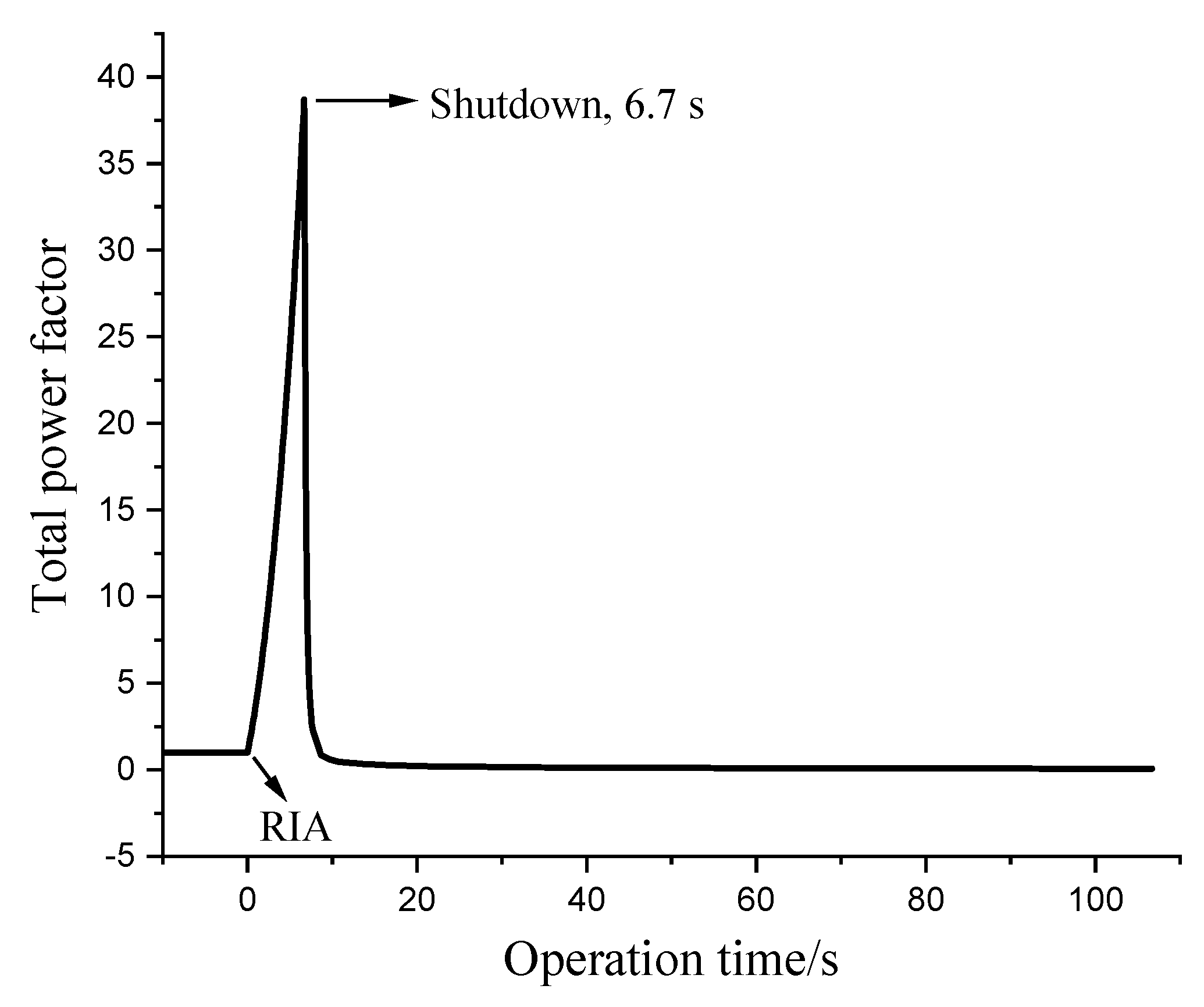
3.3. Operation Under RIA Condition

HPRs can fundamentally eliminate loss of coolant accidents and loss of flow accidents. However, in cases of control drum malfunction or sand burying, HPRs might experience RIAs. In this section, the thermo-mechanical response of the HPR under the RIA condition will be discussed. Power history during the RIA caused by the malfunction of a single control drum, obtained through the neutronics analysis [23], is shown in Figure 15. To get the most reliable results, the RIA in this study was assumed to occur at the end of the cycle; that is, the RIA occurred after 30 years of normal operation.
Figure 16 illustrates the variation of the maximum fuel temperature of Rod 2 (in the central region) and Rod 38 (in the periphery region) during the RIA. As seen in Figure 16, the maximum temperatures of both rods increased sharply and then decreased with time, with a peak temperature occurring at about 10 s (a few seconds behind the power peak). Although the peak power factor was as high as about 40, the temperature increase caused by the RIA was smaller than 200 K, which would not lead to any thermal failure risks. This is due to the design of the reactivity control system of the HPR to avoid large reactivity insertions. The variation of maximum temperature of the full-core matrix is shown in Figure 17. Similar to the fuel temperature, the matrix temperature increased sharply first and then continuously decreased, with the peak value occurring at about 27 s. Compared with the fuel temperature increase, the matrix temperature increase was much smaller because of the large mass load and high thermal conductivity of the matrix, which also proves the superiority of HPR design. Overall, the influence of thermal impact on reactor safety during the RIA was very limited compared to traditional LWRs for two reasons. First of all, the HPR design eliminates the dramatic power flash-up, which significantly reduces the total energy generated during the RIA. Secondly, the design of the solid-state core avoids the heat transfer crisis caused by the coolant phase transition in conventional reactors.
The variation of maximum matrix stress and maximum matrix displacement is illustrated in Figure 18 and Figure 19, respectively. Since the influence of the RIA on the matrix temperature was very limited, the amplitude of matrix stress and displacement variation during the RIA was relatively small, as seen in Figure 18 and Figure 19. Because Mises stress is affected by the temperature and properties that vary with temperature (thermal expansion, modulus, creep rate), it presented a complicated variation during the RIA, as seen in Figure 18. However, the maximum stress was well below the UTS limit, indicating no mechanical failure. Overall, all the results indicate that the HPR can survive well under the thermo-mechanical response during RIA.

4. Conclusions and Future Work

On the basis of thermo-mechanical analysis capability developed with ABAQUS-2021 and preliminarily validated by an out-pile experiment, the full-core simulation of an HPR proposed by Xi’an Jiao-tong University was conducted under long-term normal operation, single heat pipe failure conditions and an RIA.
During long-term normal operation, fuel temperature and matrix temperature were at very low levels compared to the melting points and remained almost unchanged. The maximum Mises stress of the matrix was also substantially lower than the corresponding strength limit and decreased gradually due to the stress release by long-term creep. Overall, the thermal and mechanical safety of this HPR was proved. However, because of the long-term creep and the superposition effect of solid-state core deformation, the matrix exhibited significant displacement over operation time. This could lead to significant variation of reactor physical parameters, which warrants further attention in reactor design and safety analysis. The failure of a single heat pipe can cause obvious temperature increases in the fuel and matrix around the failed heat pipe but has little effect on the temperature in the area far away from it. It was a benefit of the large margin of thermal safety in the HPR design that no thermal failure was found in any of the single heat pipe failure cases. The strategy of using independently operated heat pipes to enhance the reliability and robustness of the reactor was proved wise by these simulation results. However, the failure of a single heat pipe caused the increase and distortion of the local matrix deformation, and its influence on physical parameters deserves further analysis, such as its effect on reactivity and power distribution. The influence of thermo-mechanical impact on reactor safety was very limited during the RIA caused by the malfunction of a single control drum. This was because the HPR design eliminates the dramatic power flash-up during the RIA, and the solid-state core avoids the heat transfer crisis caused by the coolant phase transition in conventional reactors. Overall, the inherent safety of the HPR design was proved.
To further improve confidence in the HPR design and safety analysis, some future works are strongly suggested. First of all, the long-term creep experiment will continue, to obtain the creep characteristics and the scale of the maximum deformation of the honeycomb solid core at high temperatures. Secondly, the thermo-mechanical simulation of the HPR with multiple heat pipes failures should be carried out to determine the safe operating boundary of the HPR. What’s more, a full-core neutronic-thermo-mechanical coupling analysis is strongly recommended to improve the accuracy of simulation results, since the result in this study indicates that the deformation of the solid-state core is so considerable that it could exert significant influence on reactor physical parameters.

Author Contributions

Conceptualization, Y.D., Y.W. and G.S.; methodology, X.P., C.L. and J.N.; software, C.L. and X.P.; formal analysis, C.L. and Y.D.; investigation, C.L., J.N. and Y.D.; resources, Y.D.; writing—original draft preparation, X.P. and C.L.; writing—review and editing, Y.D.; supervision, Y.D., Y.W. and G.S. All authors have read and agreed to the published version of the manuscript.

Funding

This research was funded by the National Natural Science Foundation of China (No. U20B2012 and No. 12375172) and the Shenzhen Science and Technology Program (No. JCYJ20241202124411016).

Data Availability Statement

The data presented in this study are available on request from the corresponding authors due to the requirements from the funders.

Conflicts of Interest

The authors declare no conflicts of interest.

References

  1. Sadekin, S.; Zaman, S.; Mahfuz, M.; Sarkar, R. Nuclear power as foundation of a clean energy future: A review. Energy Procedia 2019, 160, 513–518. [Google Scholar] [CrossRef]
  2. Bayraktar, M.; Pamik, M. Nuclear power utilization as a future alternative energy on icebreakers. Nucl. Eng. Technol. 2023, 55, 580–586. [Google Scholar] [CrossRef]
  3. Yan, B.H.; Wang, C.; Li, L.G. The technology of micro heat pipe cooled reactor: A review. Ann. Nucl. Energy 2020, 135, 106948. [Google Scholar] [CrossRef]
  4. Poston, D.I. The Heat pipe-Operated Mars Exploration Reactor (HOMER). AIP Conf. Proc. 2001, 552, 797–804. [Google Scholar]
  5. Poston, D.I.; Mcclure, P.R.; Dixon, D.D. Experimental demonstration of a heat pipe–stirling engine nuclear reactor. Nucl. Technol. 2014, 188, 229–237. [Google Scholar] [CrossRef]
  6. Bess, J.D. A Basic LEGO reactor design for the provision of lunar surface power. Report of Idaho National Laboratory. In Proceedings of the International Congress on Advances in Nuclear Power Plants (ICAPP ’08), Anaheim, CA, USA, 8–12 June 2008. [Google Scholar]
  7. Bushman, A.; Carpenter, D.M.; Ellis, T.S. The Martian Surface Reactor: An Advanced Nuclear Power Station for manned Extraterrestrial Exploration; Report of Massachusetts Institute of Technology. MIT-NSA-TR-003; Massachusetts Institute of Technology: Cambridge, MA, USA, 2004. [Google Scholar]
  8. Mcclure, P.R.; Reid, R.S.; Dixon, D.D. Advantages and applications of megawatt sized heat pipe reactors. Report of Los Alamos National Lab. In Proceedings of the International Congress on Advances in Nuclear Power Plants 2012 (ICAPP 2012), Chicago, IL, USA, 24–28 June 2012. [Google Scholar]
  9. Mcclure, P.R.; Poston, D.I.; Dixon, D.D. Final Results of Demonstration Using Flattop Fissions (DUFF) Experiment. 2012. Available online: https://www.osti.gov/servlets/purl/1052794 (accessed on 5 October 2012).
  10. Alawneh, L.M.; Vaghetto, R.; Hassan, Y.; White, H.G. Conceptual design of a 3 MWth yttrium hydride moderated heat pipe cooled micro reactor. Nucl. Eng. Des. 2022, 397, 111931. [Google Scholar] [CrossRef]
  11. Choi, S.H.; Lee, S.N.; Jo, C.K.; Kim, C.S. Conceptual core design and neutronics analysis for a space heat pipe reactor using a low enriched uranium fuel. Nucl. Eng. Des. 2022, 387, 111603. [Google Scholar] [CrossRef]
  12. Wang, C.L.; Sun, H.; Tang, S.M.; Tian, W.X.; Qiu, S.Z.; Su, G.H. Thermal-hydraulic analysis of a new conceptual heat pipe cooled small nuclear reactor system. Nucl. Eng. Technol. 2020, 52, 19–26. [Google Scholar] [CrossRef]
  13. Neubert, M.; Hauser, A.; Pourhossein, B.; Dillig, M.; Karl, J. Experimental evaluation of a heat pipe cooled structured reactor as part of a two-stage catalytic methanation process in power-to-gas applications. Appl. Energy 2018, 229, 289–298. [Google Scholar] [CrossRef]
  14. Deng, Y.B.; Qiu, B.W.; Yin, Y.; Wu, Y.W.; Su, G.H. Design and evaluation of a high power density and high energy efficiency fuel element for space nuclear reactors. Appl. Therm. Eng. 2021, 191, 116915. [Google Scholar] [CrossRef]
  15. Wang, D.Q.; Yan, B.H.; Chen, J.Y. The opportunities and challenges of micro heat piped cooled reactor system with high efficiency energy conversion units. Ann. Nucl. Energy 2020, 149, 107808. [Google Scholar] [CrossRef]
  16. Yin, L.; Liu, H.P.; Liu, W.Q. Capillary character and evaporation heat transfer in the wicks of high temperature liquid metal heat pipe. Appl. Therm. Eng. 2020, 175, 115284. [Google Scholar] [CrossRef]
  17. Panda, K.K.; Dulera, I.V.; Basak, A. Numerical simulation of high temperature sodium heat pipe for passive heat removal in nuclear reactors. Nucl. Eng. Des. 2017, 323, 376–385. [Google Scholar] [CrossRef]
  18. Ma, Y.G.; Chen, E.H.; Yu, H.X.; Zhong, R.C.; Deng, J.; Chai, X.M.; Huang, S.F.; Ding, S.H.; Zhang, Z.H. Heat pipe failure accident analysis in megawatt heat pipe cooled reactor. Ann. Nucl. Energy 2020, 149, 107755. [Google Scholar] [CrossRef]
  19. Ma, Y.G.; Tian, C.Q.; Yu, H.X.; Zhong, R.C.; Zhang, Z.H.; Huang, S.F.; Deng, J.; Chai, X.M.; Yang, Y.J. Transient heat pipe failure accident analysis of a megawatt heat pipe cooled reactor. Prog. Nucl. Energy 2021, 140, 103904. [Google Scholar] [CrossRef]
  20. Laubscher, R.; Dobson, R.T. Theoretical and experimental modelling of a heat pipe heat exchanger for high temperature nuclear reactor technology. Appl. Therm. Eng. 2013, 61, 259–267. [Google Scholar] [CrossRef]
  21. Chen, X.W.; Zou, Y.; Chen, Z.H.; Dai, Y. Effect of core configuration on natural convection and heat transfer in heat pipe cooled micro-MSRs. Nucl. Eng. Des. 2022, 395, 111839. [Google Scholar] [CrossRef]
  22. Li, T.; Xiong, J.B.; Zhang, T.F.; Chai, X.; Liu, X.J. Multi-physics coupled simulation on steady-state and transients of heat pipe cooled reactor system. Ann. Nucl. Energy 2023, 187, 109774. [Google Scholar] [CrossRef]
  23. Nie, J.Y.; Li, B.Q.; Wu, Y.W.; Zhang, J.; He, Y.N.; Zhang, G.L.; Ren, Q.S.; Su, G.H. Thermo-neutronics coupled simulation of a heat pipe reactor based on OPENMC/COMSOL. In Proceedings of the 2024 31st International Conference on Nuclear Engineering, 4, ICONE31, Prague, Czech Republic, 4–8 August 2024. [Google Scholar]
  24. Hales, J.D.; Williamson, R.L.; Novascone, S.R. The Equations Behind Nuclear Fuel Analysis, BISON Theory Manual; Idaho National Laboratory: Idaho Falls, ID, USA, 2018. [Google Scholar]
  25. William, C.; Artem, A.; David, H. Development of Additive Manufacturing at Westinghouse. In Proceedings of the Top Fuel, Seattle, WA, USA, 22–27 September 2019. [Google Scholar]
  26. Macdonald, P.E.; Thompson, L.B. MATPRO: A Handbook of Materials Properties for Use in the Analysis of Light Water Reactor Fuel Rod Behavior; Specific Nuclear Reactors & Associated Plants; AEROJET Nuclear Company: Rancho Cordova, CA, USA, 1976. [Google Scholar]
  27. Deng, Y.B.; Wu, Y.W.; Li, Y.M.; Zhang, D.L.; Tian, W.X.; Su, G.H.; Qiu, S.Z. Mechanism study and theoretical simulation on heat split phenomenon in dual-cooled annular fuel element. Ann. Nucl. Energy 2016, 94, 44–54. [Google Scholar] [CrossRef]
  28. Cox, B. Pellet-clad interaction (PCI) failures of zirconium alloy fuel cladding—A review. J. Nucl. Mater. 1990, 172, 249–292. [Google Scholar] [CrossRef]
Figure 1. Design scheme of the HPR core.
Energies 18 01423 g001
Figure 2. Design of the out-pile thermo-mechanical experiment: (a) Design diagram, (b) Real picture of the experiment device, (c) Front view of the test section, (d) Back view of the test section, (e) Image captured by industrial camera and (f) Image captured by infrared camera.
Energies 18 01423 g002
Figure 3. Comparison of the matrix temperature during long-term normal steady-state operation.
Energies 18 01423 g003
Figure 4. Comparison of x displacement under the failure condition of a single heat pipe.
Energies 18 01423 g004
Figure 5. Comparison of matrix displacement variation over time under the long-term high-temperature creep condition.
Energies 18 01423 g005
Figure 6. Geometry, mesh and boundary conditions for HPR thermo-mechanical simulation.
Energies 18 01423 g006
Figure 7. Core matrix profile of temperature at the end of operation (left) and variation of maximum matrix temperature over time (right).
Energies 18 01423 g007
Figure 8. Core matrix profile of Mises stress at the end of operation (left) and variation of maximum matrix Mises stress over time (right).
Energies 18 01423 g008
Figure 9. Core matrix profile of creep strain at the end of operation (left) and variation of maximum matrix creep strain over time (right).
Energies 18 01423 g009
Figure 10. Core matrix profile of principal strain at the end of operation (left) and core matrix profile of displacement magnitude at the end of operation (right).
Energies 18 01423 g010
Figure 11. Core profile (with fuels) of temperature in K at the end of operation (left) and variation of maximum fuel temperature over time (right).
Energies 18 01423 g011
Figure 12. The label of the failed heat pipe with the consideration of symmetry of core geometry.
Energies 18 01423 g012
Figure 13. The influence of single heat pipe failure on core matrix temperature profile.
Energies 18 01423 g013
Figure 14. The influence of single heat pipe failure on core fuel temperature profile.
Energies 18 01423 g014
Figure 15. Total power factor of the HPR during the RIA.
Energies 18 01423 g015
Figure 16. Variation of maximum fuel temperature versus time.
Energies 18 01423 g016
Figure 17. Variation of maximum matrix temperature versus time.
Energies 18 01423 g017
Figure 18. Variation of maximum matrix stress versus time.
Energies 18 01423 g018
Figure 19. Variation of maximum matrix displacement versus time.
Energies 18 01423 g019
Table 1. Design parameters of the HPR core.
ParameterValueParameterValue
Total thermal power500 kWCore diameter0.835 m
Core active length0.400 mSide reflector diameter1.180 m
Bottom/top reflector length0.200 mRod/pipe pitch0.065 m
Control drum number6Control drum diameter0.070 m
Type 1 fuel rod number6Type 2 fuel rod number30
Type 1 fuel rod diameter0.054 mType 2 fuel rod diameter0.054 m
Type 1 fuel/clad materialUO2/SS316Type 2 fuel/clad materialUO2/SS316
Type 1 fuel enrichment14.75%Type 2 fuel enrichment19.75%
Type 3 fuel rod number18Heat pipe number37
Type 3 fuel rod diameter0.054 mHeat pipe diameter0.052 m
Type 3 fuel/clad materialUO2/SS316Heat pipe length0.200 m
Type 3 fuel enrichment19.25%Heat pipe materialSS316/Na
Table 2. Power factors of fuel rods.
Rod NOPower FactorRod NOPower FactorRod NOPower Factor
11.172191.076370.902
21.146200.921380.866
31.144211.168390.885
41.153221.167400.868
51.122230.907410.911
61.142241.072420.863
70.926251.124430.880
80.921260.948440.885
90.940271.069450.860
101.090281.174460.893
111.085291.175470.882
120.958301.119480.895
131.082310.919490.867
141.165321.08500.875
151.166331.083510.892
161.065340.946520.901
170.925350.913530.903
181.097360.926540.877
Table 3. Summary of maximum parameters under different operation conditions.
CaseMax Fuel
Temperature/K
Max Matrix
Temperature/K
Max Matrix Stress/MPaMax Matrix
Displacement/mm
No failure1419834237.73.68
Pipe 1 failure14191096237.63.68
Pipe 2 failure14191093238.03.68
Pipe 3 failure16401111238.13.94
Pipe 4 failure1486901238.44.09
Pipe 5 failure15551093237.43.96
Pipe 6 failure1561946238.24.47
Disclaimer/Publisher’s Note: The statements, opinions and data contained in all publications are solely those of the individual author(s) and contributor(s) and not of MDPI and/or the editor(s). MDPI and/or the editor(s) disclaim responsibility for any injury to people or property resulting from any ideas, methods, instructions or products referred to in the content.

