
Experimental Study on Factors Influencing the Propagation of Hydraulic Fractures in Shale Reservoirs with Developed Natural Weak Planes

Abstract
1. Introduction
2. Reservoir Characteristics and Physical Model Similarity Design
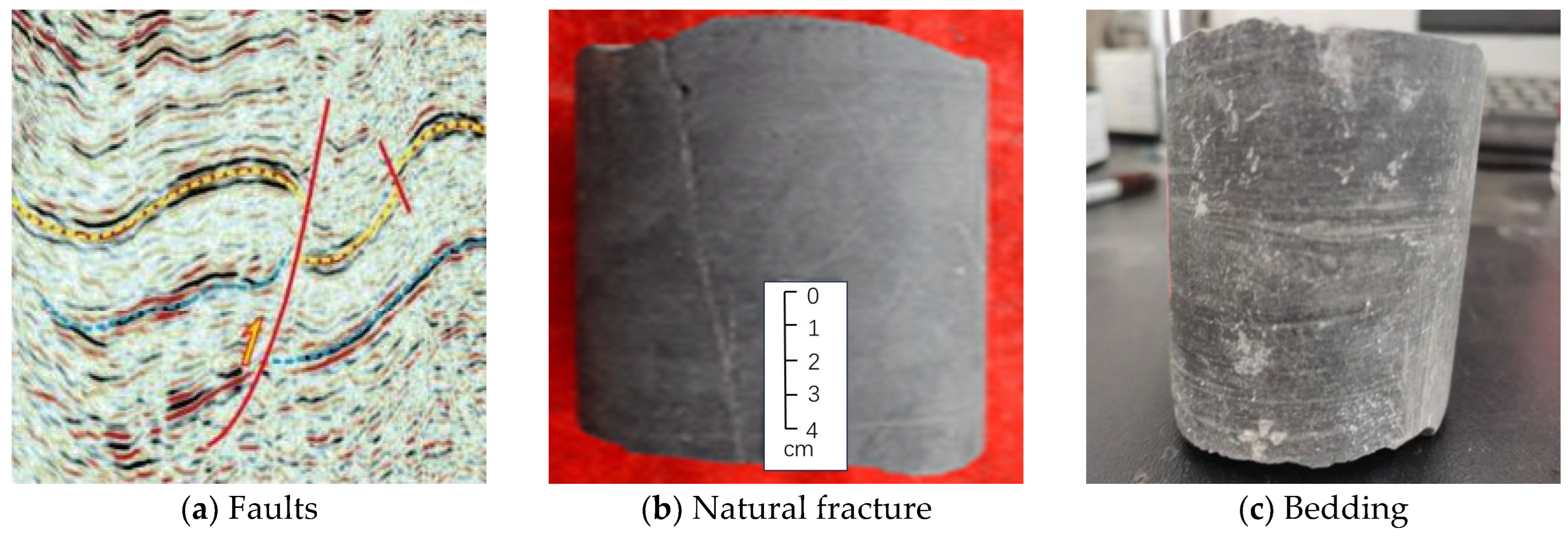
2.1. Development Characteristics of Natural Weak Planes in Shale Reservoirs
2.2. Physical Model Similarity Design
3. Experimental Plan Design
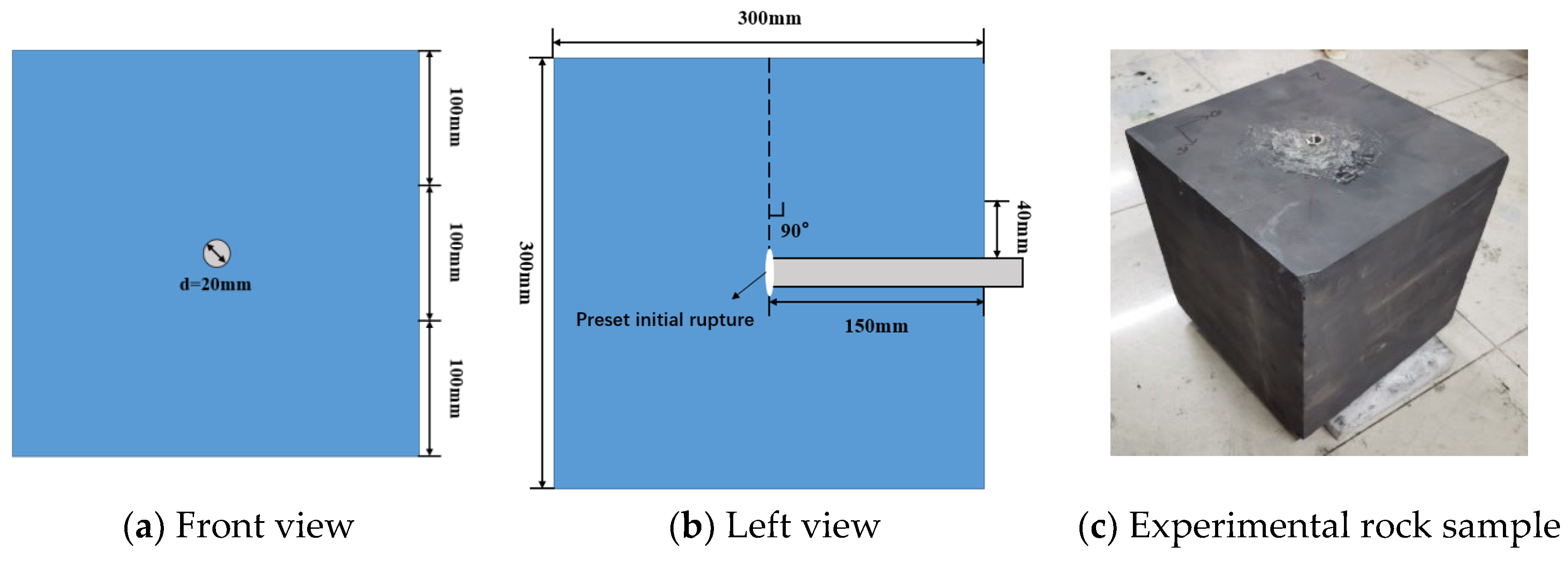
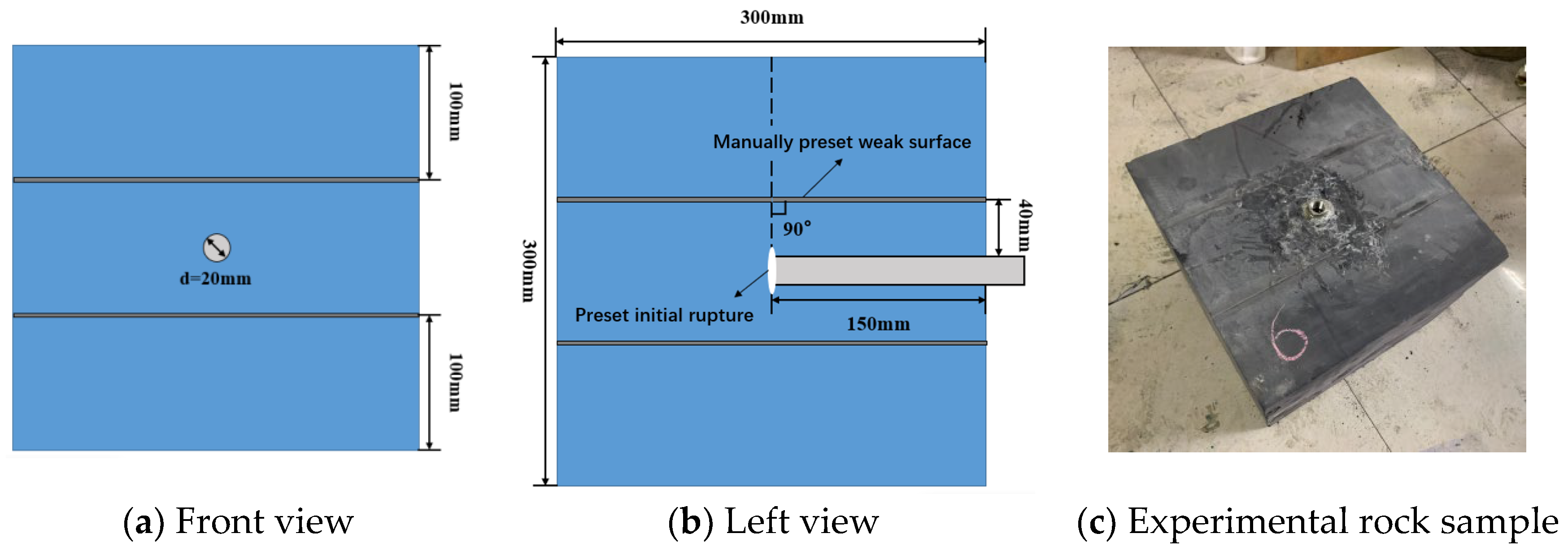
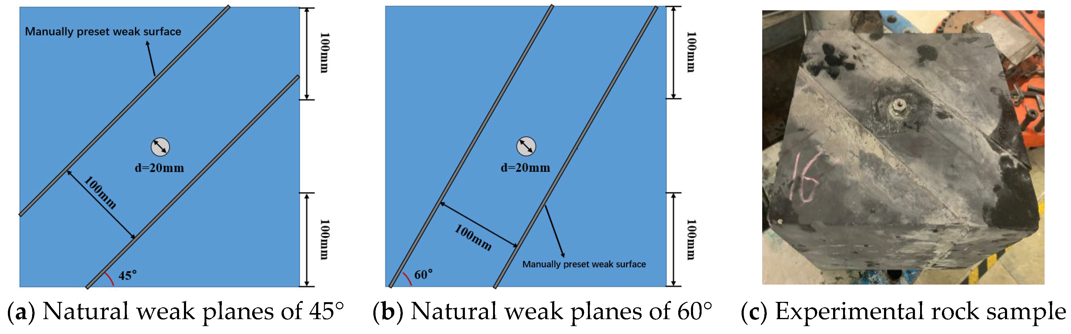
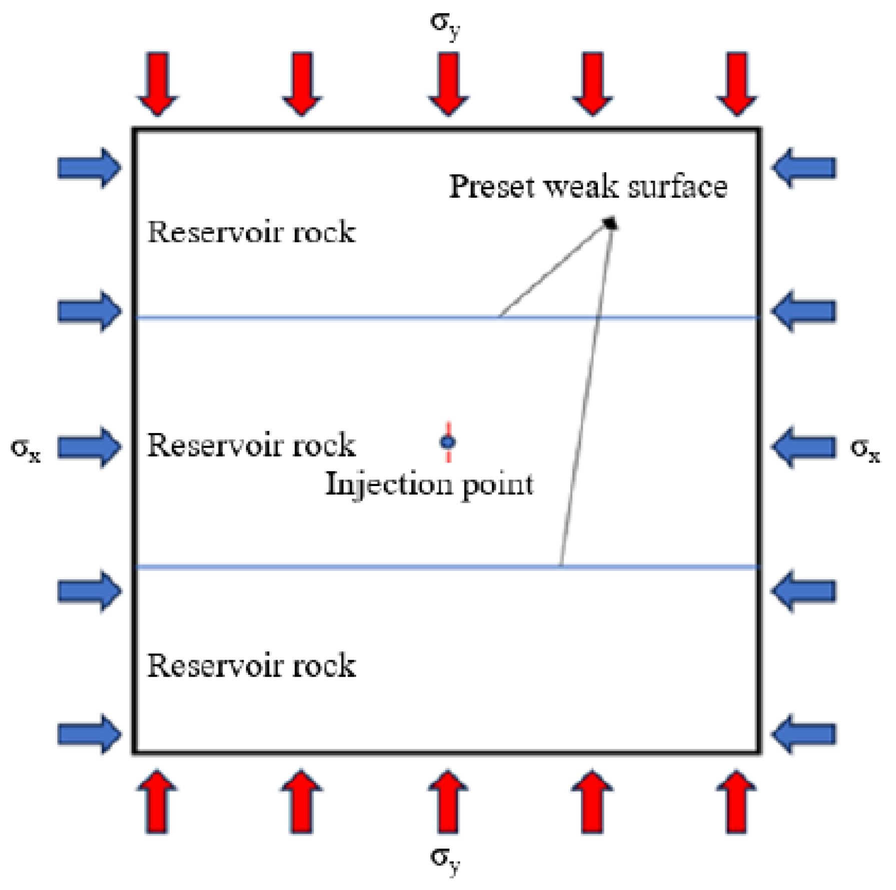
3.1. Model Design and Fabrication
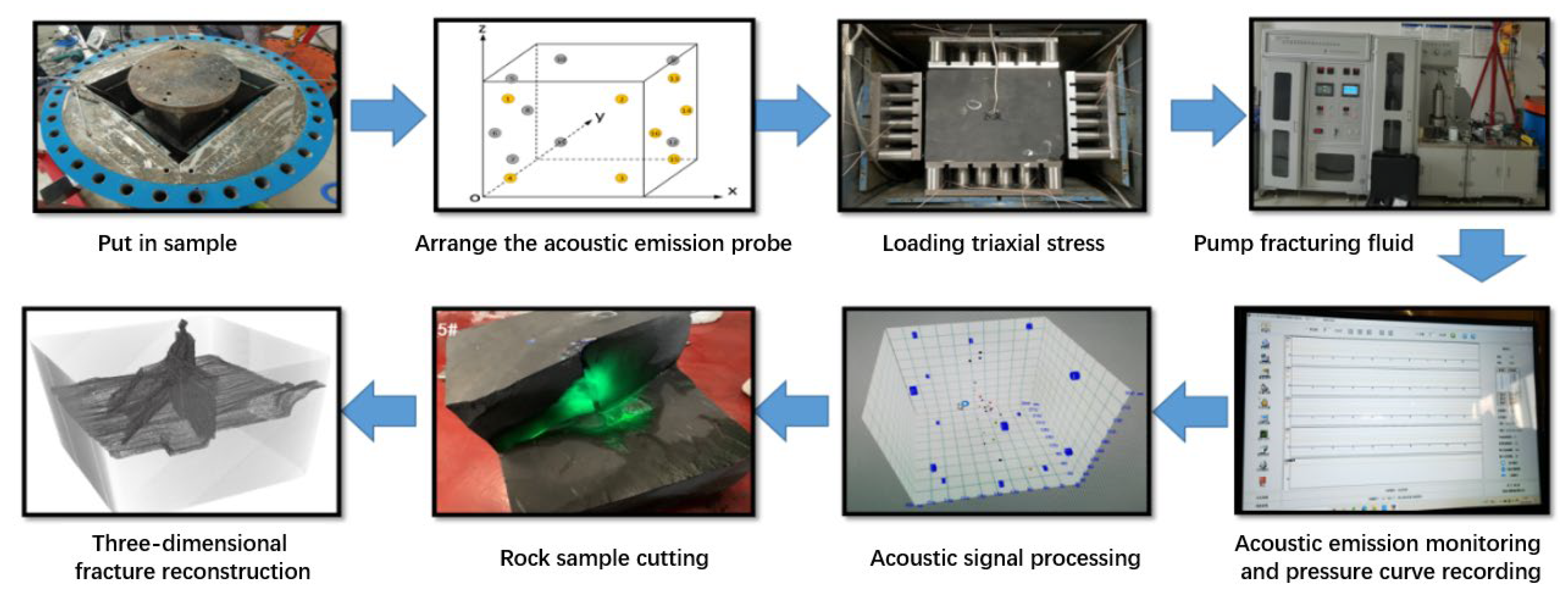
3.2. Experimental Equipment and Procedure
3.3. Experimental Plan
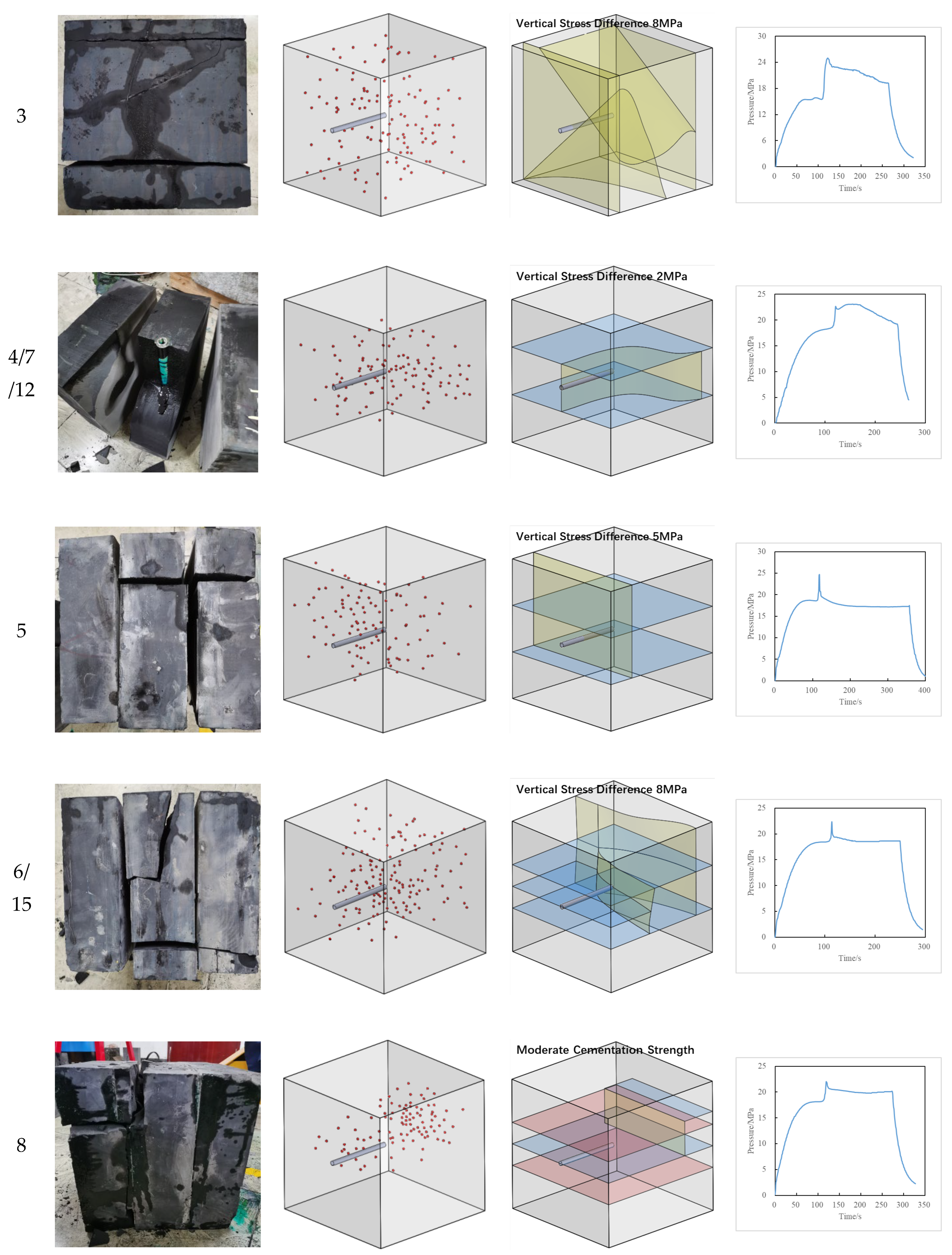
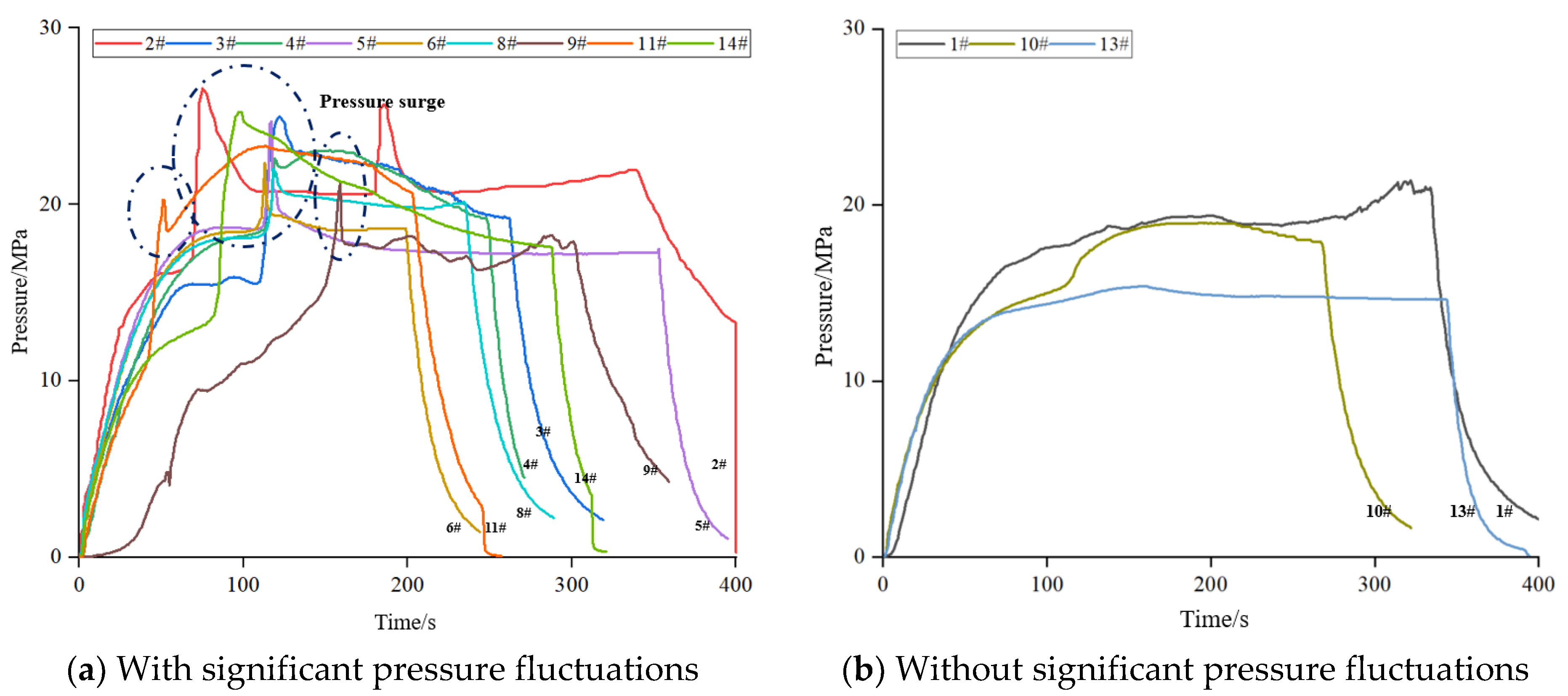
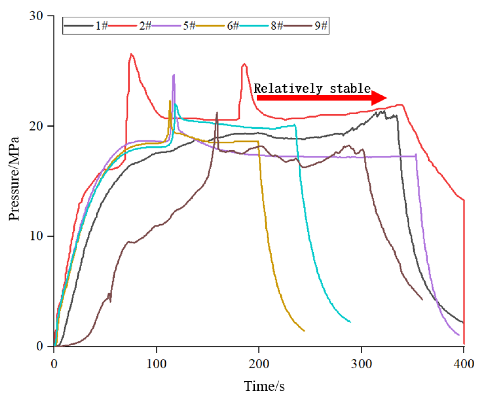
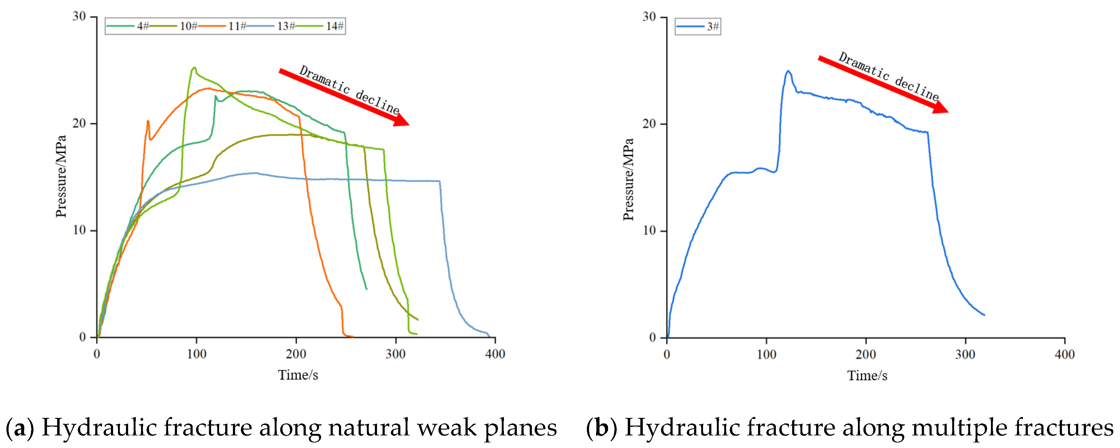
4. Experimental Results Analysis
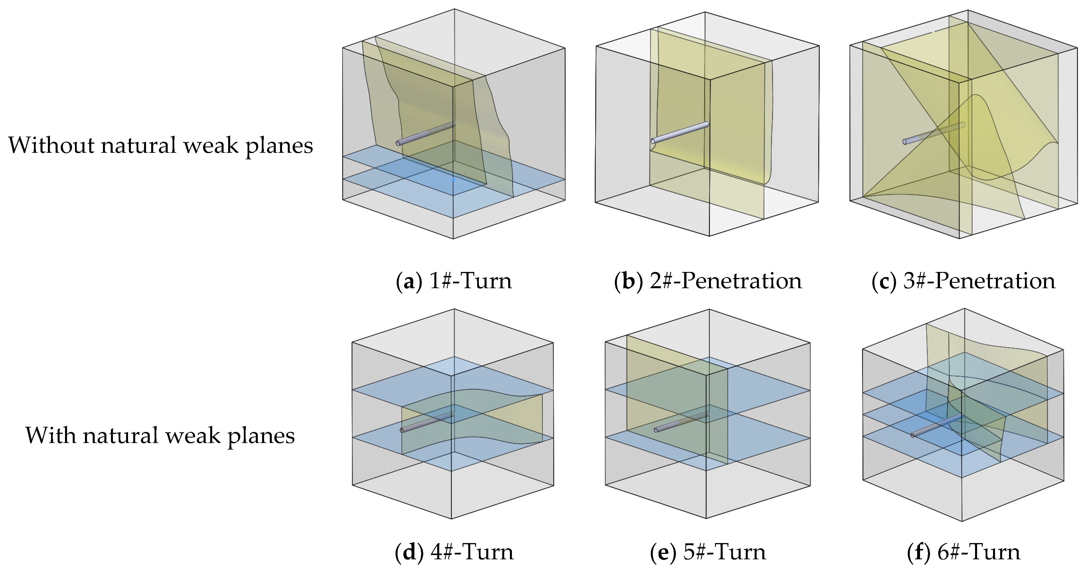
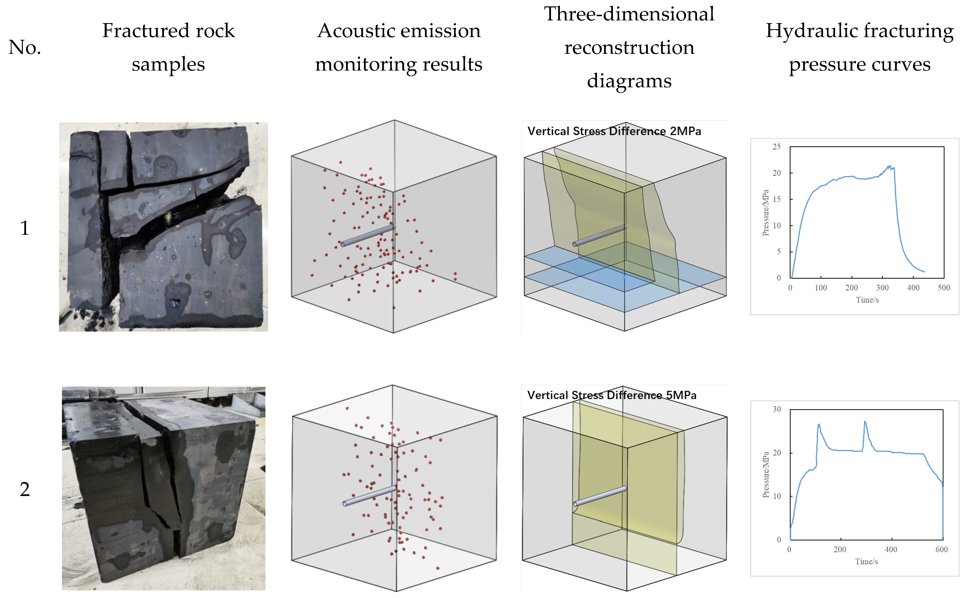
4.1. Analysis of Fracture Evolution Characteristics
- (1)
- Initiation Characteristics of Hydraulic Fractures
- (2)
- Hydraulic Fracture Propagation and Distribution Characteristics
4.2. Analysis of Influencing Factors
- (1)
- Development of Natural Weaknesses
- (2)
- Vertical Stress Difference
- (3)
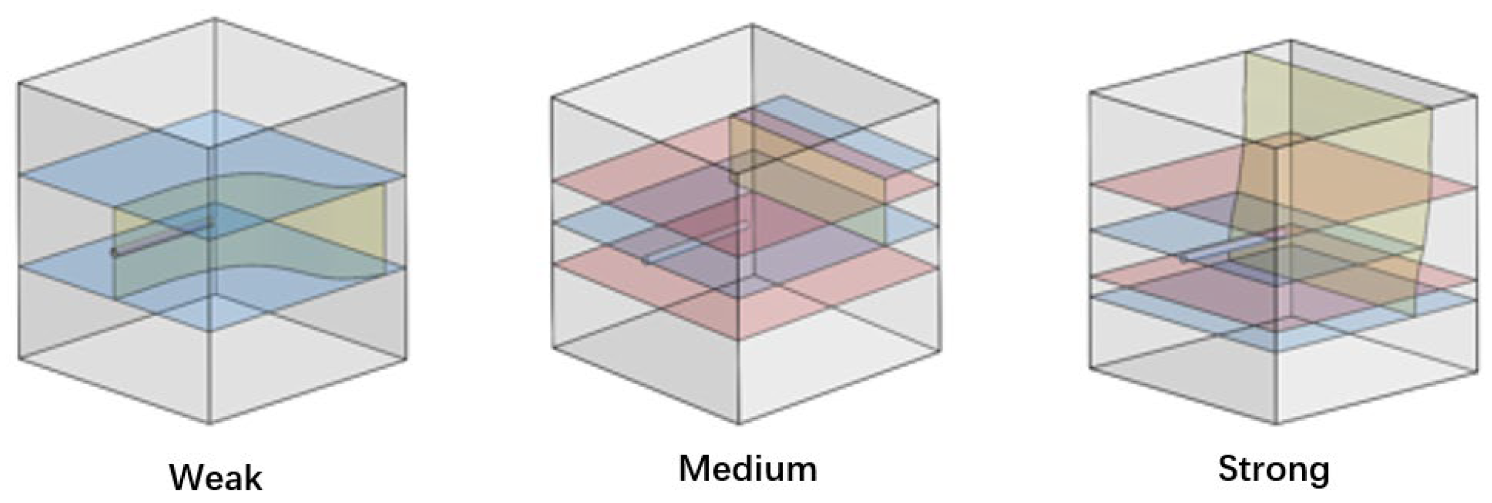
- Natural Weak-Plane Cementation Strength
- (4)
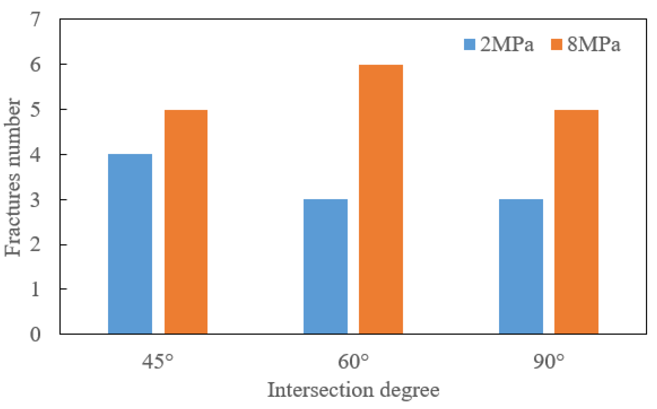
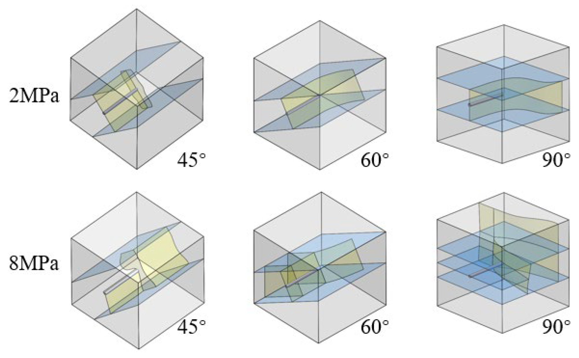
- Intersection Angle
5. Conclusions
Author Contributions
Funding
Data Availability Statement
Conflicts of Interest
References
- Qian, X.; Lu, R.; Luo, L. Global oil and gas industry in 2023 and outlook for 2024. Int. Pet. Econ. 2024, 32, 1–13. [Google Scholar]
- Chen, X.; Huang, Y.; Li, Y.; Shen, C. Numerical simulation study on evolution law of three-dimensional fracture network in unconventional reservoirs. Front. Energy Res. 2024, 11, 1337069. [Google Scholar] [CrossRef]
- Gao, Y.; Wang, B.; Hu, Y.; Gao, Y.; Hu, A. Development of China’s natural gas: Review 2023 and outlook 2024. Nat. Gas Ind. 2024, 44, 166–177. [Google Scholar]
- Lei, L.; Li, Y.; Peng, Z. Viewing China’s Oil and Gas Resource Strategy from the Development Situation of World Oil and Gas Resources. Sino-Glob. Energy 2019, 24, 1–7. [Google Scholar]
- Chen, J.; Wang, N.; Tang, H.; Li, J.; Xiong, B. Impact of sustained low oil prices on China’s oil & gas industry system and coping strategies. Nat. Gas Ind. 2016, 36, 1–6. [Google Scholar]
- Boyer, C.; Clark, B.; Jochen, V.; Lewis, R.; Miller, C.K. Shale gas: A global resource. Oilfield Rev. 2011, 23, 28–39. [Google Scholar]
- Rodriguez, N.D.; Philp, R.P. Geochemical characterization of gases from the Mississippian Barnett shale, Fort Worth basin, Texas. AAPG Bull. 2010, 94, 1641–1656. [Google Scholar] [CrossRef]
- Zhang, F.; Li, G.; Zheng, X.; Wu, Q.; Li, Z.; Qi, Z.; Wang, J.; Zhang, L. Enlightenment from the post shale revolution era in North America. China Pet. Explor. 2022, 27, 26–39. [Google Scholar]
- Dou, L.; Li, D.; Wen, Z.; Wang, Z.; Mi, S.; Zhang, Q. History and outlook of global oil and gas resources evaluation. Acta Pet. Sin. 2022, 43, 1035–1048. [Google Scholar]
- Sohail, G.M.; Radwan, A.E.; Mahmoud, M. A review of Pakistani shales for shale gas exploration and comparison to North American shale plays. Energy Rep. 2022, 8, 6423–6442. [Google Scholar] [CrossRef]
- Bellani, J.; Verma, H.K.; Khatri, D.; Makwana, D.; Shah, M. Shale gas: A step toward sustainable energy future. J. Pet. Explor. Prod. Technol. 2021, 11, 2127–2141. [Google Scholar] [CrossRef]
- Syed, F.I.; Alnaqbi, S.; Muther, T.; Dahaghi, A.K.; Negahban, S. Smart shale gas production performance analysis using machine learning applications. Pet. Res. 2022, 7, 21–31. [Google Scholar] [CrossRef]
- Zhao, J.; Ren, L.; Jiang, T.; Hu, D.; Wu, L.; Wu, J.; Yin, C.; Li, Y.; Hu, Y.; Lin, R.; et al. Ten years of gas shale fracturing in China: Review and prospect. Nat. Gas Ind. B 2022, 9, 158–175. [Google Scholar] [CrossRef]
- Omari, A.; Wang, C.; Li, Y.; Xu, X. The progress of enhanced gas recovery (EGR) in shale gas reservoirs: A review of theory, experiments, and simulations. J. Pet. Sci. Eng. 2022, 213, 110461. [Google Scholar] [CrossRef]
- Guo, X.; Borjigin, T.; Wei, X.; Yu, L.; Lu, X.; Sun, L.; Wei, F. Occurrence mechanism and exploration potential of deep marine shale gas in Sichuan Basin. Acta Pet. Sin. 2022, 43, 453–468. [Google Scholar]
- Nie, H.; He, Z.; Liu, G.; Du, W.; Wang, R.; Zhang, G. Genetic mechanism of high-quality shale gas reservoirs in the Wufeng–LongmaxiFms in the Sichuan Basin. Nat. Gas Ind. B 2021, 8, 24–34. [Google Scholar] [CrossRef]
- Zhai, G.; Wang, Y.; Zhou, Z.; Yu, S.; Chen, X.; Zhang, Y. Exploration and research progress of shale gas in China. China Geol. 2018, 1, 257–272. [Google Scholar] [CrossRef]
- Solarin, S.A.; Gil-Alana, L.A.; Lafuente, C. An investigation of long range reliance on shale oil and shale gas production in the US market. Energy 2020, 195, 116933. [Google Scholar] [CrossRef]
- Lecampion, B.; Bunger, A.; Zhang, X. Numerical methods for hydraulic fracture propagation: A review of recent trends. J. Nat. Gas Sci. Eng. 2018, 49, 66–83. [Google Scholar] [CrossRef]
- Sampath, K.; Perera, M.S.A.; Ranjith, P.G. Theoretical overview of hydraulic fracturing break-down pressure. J. Nat. Gas Sci. Eng. 2018, 58, 251–265. [Google Scholar] [CrossRef]
- Liu, X.; Rasouli, V.; Guo, T. Numerical simulation of stress shadow in multiple cluster hydraulic fracturing in horizontal wells based on lattice modelling. Eng. Fract. Mech. 2020, 238, 107278. [Google Scholar] [CrossRef]
- Li, N.; Zhang, S.; Zou, Y.; Ma, X.; Zhang, Z.; Li, S.; Chen, M.; Sun, Y. Acoustic Emission Response of Laboratory Hydraulic Fracturing in Layered Shale. Rock Mech. Rock Eng. 2018, 51, 3395–3406. [Google Scholar] [CrossRef]
- AlTammar, M.J.; Agrawal, S.; Sharma, M.M. Effect of geological layer properties on hydraulic-fracture initiation and propagation: An experimental study. SPE J. 2019, 24, 757–794. [Google Scholar] [CrossRef]
- Li, Y.; Hu, W.; Zhang, Z.; Zhang, Z.; Shang, Y.; Han, L.; Wei, S. Numerical simulation of hydraulic fracturing process in a naturally fractured reservoir based on a discrete fracture network model. J. Struct. Geol. 2021, 147, 104331. [Google Scholar] [CrossRef]
- Huang, L.; Tan, J.; Fu, H.; Liu, J.; Chen, X.; Liao, X.; Wang, X.; Wang, C. The non-plane initiation and propagation mechanism of multiple hydraulic fractures in tight reservoirs considering stress shadow effects. Eng. Fract. Mech. 2023, 292, 109570. [Google Scholar] [CrossRef]
- Chen, X.; Zhao, J.; Li, Y.; Yan, W.; Zhang, X. Numerical simulation of simultaneous hydraulic fracture growth within a rock layer. Implic. Stimul. Low-Permeability Reserv. 2019, 124, 13227–13249. [Google Scholar]
- Yaghoubi, A. Hydraulic fracturing modeling using a discrete fracture network in the Barnett Shale. Int. J. Rock Mech. Min. Sci. 2019, 119, 98–108. [Google Scholar] [CrossRef]
- Zheng, P.; Xia, Y.; Yao, T.; Jiang, X.; Xiao, P.; He, Z.; Zhou, D. Formation mechanisms of hydraulic fracture network based on fracture interaction. Energy 2022, 243, 123057. [Google Scholar] [CrossRef]
- Wang, H. Hydraulic fracture propagation in naturally fractured reservoirs: Complex fracture or fracture networks. J. Nat. Gas Sci. Eng. 2019, 68, 102911. [Google Scholar] [CrossRef]
- Rahimi-Aghdam, S.; Chau, V.-T.; Lee, H.; Nguyen, H.; Li, W.; Karra, S.; Rougier, E.; Viswanathan, H.; Srinivasan, G.; Bažant, Z.P. Branching of hydraulic cracks enabling permeability of gas or oil shale with closed natural fractures. Proc. Natl. Acad. Sci. USA 2019, 116, 1532–1537. [Google Scholar] [CrossRef] [PubMed]
- Zhang, F.; Damjanac, B.; Maxwell, S. Investigating hydraulic fracturing complexity in naturally fractured rock masses using fully coupled multiscale numerical modeling. Rock Mech. Rock Eng. 2019, 52, 5137–5160. [Google Scholar] [CrossRef]
- Kolawole, O.; Ispas, I. Interaction between hydraulic fractures and natural fractures: Current status and prospective directions. J. Pet. Explor. Prod. Technol. 2020, 10, 1613–1634. [Google Scholar] [CrossRef]
- Taleghani, A.D.; Gonzalez-Chavez, M.; Yu, H.; Asala, H.; Hao, H. Numerical simulation of hydraulic fracture propagation in naturally fractured formations using the cohesive zone model. J. Pet. Sci. Eng. 2018, 165, 42–57. [Google Scholar] [CrossRef]
- Zhou, Z.; Hou, Z.; Guo, Y.; Zhao, H.; Wang, D.; Qiu, G.; Guo, W. Experimental study of hydraulic fracturing for deep shale reservoir. Eng. Fract. Mech. 2024, 37, 110259. [Google Scholar] [CrossRef]
- Tang, J.; Wu, K.; Li, Y.; Hu, X.; Liu, Q.; Ehlig-Economides, C. Numerical investigation of the interactions between hydraulic fracture and bedding planes with non-orthogonal approach angle. Eng. Fract. Mech. 2018, 200, 1–16. [Google Scholar] [CrossRef]
- Cleary, M.P. Analysis of Mechanisms and Procedures for Producing Favourable Shapes of Hydraulic Fractures. In Proceedings of the SPE Annual Technical Conference and Exhibition, Dallas, TX, USA, 21–24 September 1980. [Google Scholar]
- Settari, A.; Cleary, M.P. Development and Testing of a Pseudo-Three-Dimensional Model of Hydraulic Fracture Geometry. SPE Prod. Eng. 1986, 1, 449–466. [Google Scholar] [CrossRef]
- Clifton, R.J.; Abou-Sayed, A.S. On the Computation of the Three-Dimensional Geometry of Hydraulic Fractures. In Proceedings of the Symposium on Low Permeability Gas Reservoirs, Denver, CO, USA, 20–22 May 1979. [Google Scholar]
- Clifton, R.J.; Abou-Sayed, A.S. A Variational Approach to the Prediction of the Three-Dimensional Geometry of Hydraulic Fractures. In Proceedings of the SPE/DOE Low Permeability Gas Reservoirs Symposium, Denver, CO, USA, 27–29 May 1981. [Google Scholar]
- Chen, X. Numerical Investigation of Non-Uniform Fracture Growth in Multi-Stage Hydraulic Fracturing. Ph.D. Thesis, Southwest Petroleum University, Chengdu, China, 2018. [Google Scholar]


| Energy Type | Proportion of Energy Consumption |
|---|---|
| oil | 31.60% |
| coal | 26.40% |
| natural gas | 23.70% |
| renewable resources | 7.30% |
| hydropower | 6.70% |
| nuclear energy | 4.30% |
| No. | Reservoir Type | Influence Factor | Value |
|---|---|---|---|
| 1 | Without Natural Weak Planes | Vertical Stress Difference | 2 MPa |
| 2 | 5 MPa | ||
| 3 | 8 MPa | ||
| 4 | With Natural Weak Planes | Vertical Stress Difference | 2 MPa |
| 5 | 5 MPa | ||
| 6 | 8 MPa | ||
| 7 | Natural Weakness Cementation Strength | Weak (about 0.5 MPa) | |
| 8 | Moderate (about 1 MPa) | ||
| 9 | Strong (about 2 MPa) | ||
| 10 | Intersection Angle (2 MPa) | 45° | |
| 11 | 60° | ||
| 12 | 90° | ||
| 13 | Intersection Angle (8 MPa) | 45° | |
| 14 | 60° | ||
| 15 | 90° |
| No. | Type | Simplified Diagram | Extended Mode (Relationship with Natural Weak Plane) | Pressure Change |
|---|---|---|---|---|
| a | Transverse fracture (without natural weak planes) |  | Vertical | Rising or relatively stable |
| b | Transverse fracture (with natural weak planes) |  | Vertical | Rising or relatively stable |
| c | I-shape fracture (or T-shaped fracture) | 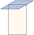 | first vertical and then parallel | Decline |
| d | Composite fracture | 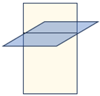 | At the same time | Rising or relatively stable |
| e | Complex fracture network | 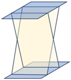 | Irregularity | Decline |
 | ||||
| No. | Fracture Initiation Mode | Fracture Propagation Mode | Whether to Break Through the Natural Weak Planes Limit |
|---|---|---|---|
| 1 | B | a | × |
| 2 | A | a | √ |
| 3 | A | c | √ |
| 4/7/12 | A | b | × |
| 5 | A | a | √ |
| 6/15 | A | a | √ |
| 8 | A | a | √ |
| 9 | A | a | √ |
| 10 | B | b | × |
| 11 | A | b | × |
| 13 | B | b | × |
| 14 | A | b | × |
Disclaimer/Publisher’s Note: The statements, opinions and data contained in all publications are solely those of the individual author(s) and contributor(s) and not of MDPI and/or the editor(s). MDPI and/or the editor(s) disclaim responsibility for any injury to people or property resulting from any ideas, methods, instructions or products referred to in the content. |
© 2025 by the authors. Licensee MDPI, Basel, Switzerland. This article is an open access article distributed under the terms and conditions of the Creative Commons Attribution (CC BY) license (https://creativecommons.org/licenses/by/4.0/).
Share and Cite
Huang, Y.; Zhu, J.; Li, Y.; He, L.; Fang, Z.; Chen, X. Experimental Study on Factors Influencing the Propagation of Hydraulic Fractures in Shale Reservoirs with Developed Natural Weak Planes. Energies 2025, 18, 1100. https://doi.org/10.3390/en18051100
Huang Y, Zhu J, Li Y, He L, Fang Z, Chen X. Experimental Study on Factors Influencing the Propagation of Hydraulic Fractures in Shale Reservoirs with Developed Natural Weak Planes. Energies. 2025; 18(5):1100. https://doi.org/10.3390/en18051100
Chicago/Turabian StyleHuang, Yitao, Juhui Zhu, Yongming Li, Le He, Zeben Fang, and Xiyu Chen. 2025. "Experimental Study on Factors Influencing the Propagation of Hydraulic Fractures in Shale Reservoirs with Developed Natural Weak Planes" Energies 18, no. 5: 1100. https://doi.org/10.3390/en18051100
APA StyleHuang, Y., Zhu, J., Li, Y., He, L., Fang, Z., & Chen, X. (2025). Experimental Study on Factors Influencing the Propagation of Hydraulic Fractures in Shale Reservoirs with Developed Natural Weak Planes. Energies, 18(5), 1100. https://doi.org/10.3390/en18051100